Numerical Investigation of the Thermal Management Performance of MEPCM Modules for PV Applications


Abstract
:1. Introduction
2. Mathematical Treatment of the Simulation and Numerical Methods
2.1. Test Cell
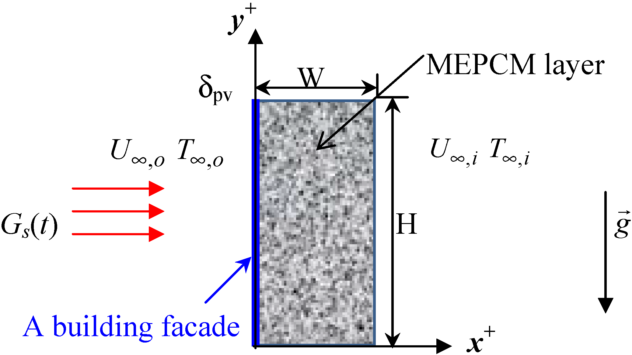
2.2. PV/MEPCM Model
- (1)
- Because the temperature gradient along the thickness δpv of the PV cell is negligibly small, the conduction is one-dimensional and takes place along its length Lpv (>>δpv);
- (2)
- The thermal properties of the PV cell are isotropic and constant;
- (3)
- The ohmic losses in the PV cell are negligible, and the photovoltaic efficiency is a function of temperature;
- (4)
- The time-dependent solar irradiation onto the outer surface of the PV cell is uniform at Gs(t);
- (5)
- The outer surface of the PV cell has an effective absorptivity of αr,pv;
- (6)
- The rectangular MEPCM layer is treated as an air-filled isotropic and homogenous porous medium with a porosity of ϕf;
- (7)
- The MEPCM particles are spheres of uniform diameter in local thermal equilibrium with the fluid, except during the solid-liquid phase change process;
- (8)
- The thermophysical properties of the fluid and the MEPCM particles are constant except for the density variation for the buoyancy force, which is treated using the Boussinesq approximation.
2.3. Dimensional Mathematical Model
2.3.1. Photovoltaic Cell Energy Balance
2.3.2. MEPCM Mathematical Equation
2.3.2.1. Momentum Equation
2.3.2.2. Stream Function—Vorticity Equations
2.3.2.3. Energy Balance
2.3.2.4. Melting Fraction Equation
2.3.3. Initial and Boundary Conditions
2.3.3.1. PV Layer Initial and Boundary Condition
2.3.3.2. MEPCM Layer Initial and Boundary Condition
2.3.4. Formulation for PV/MEPCM Composite Layer under Temporal Variations of Solar Irradiation and Exterior Ambient Temperature
2.4. Properties and used parameters
2.5. Numerical Method
2.6. Quantities of Technical Interest
3. Results and Discussion
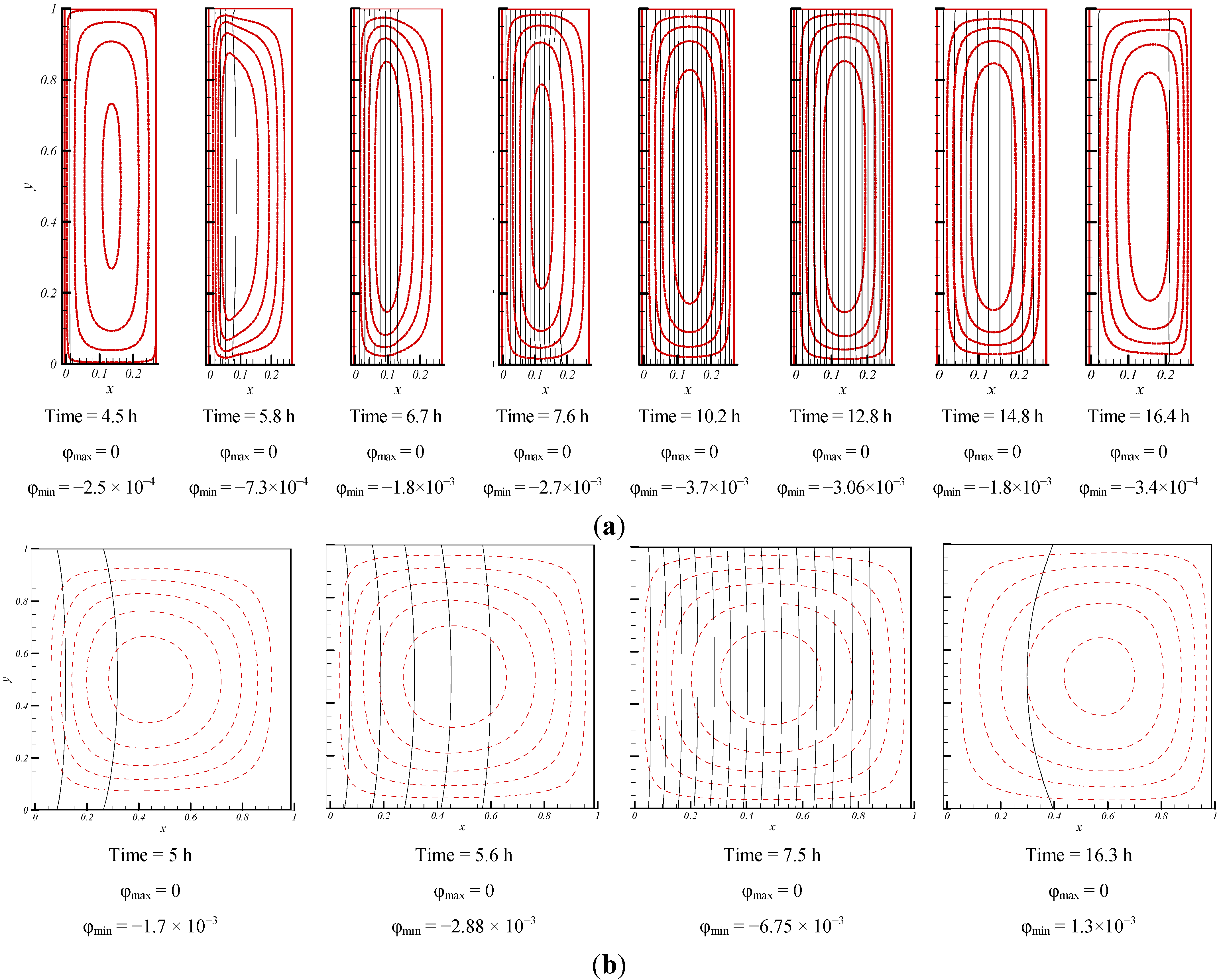
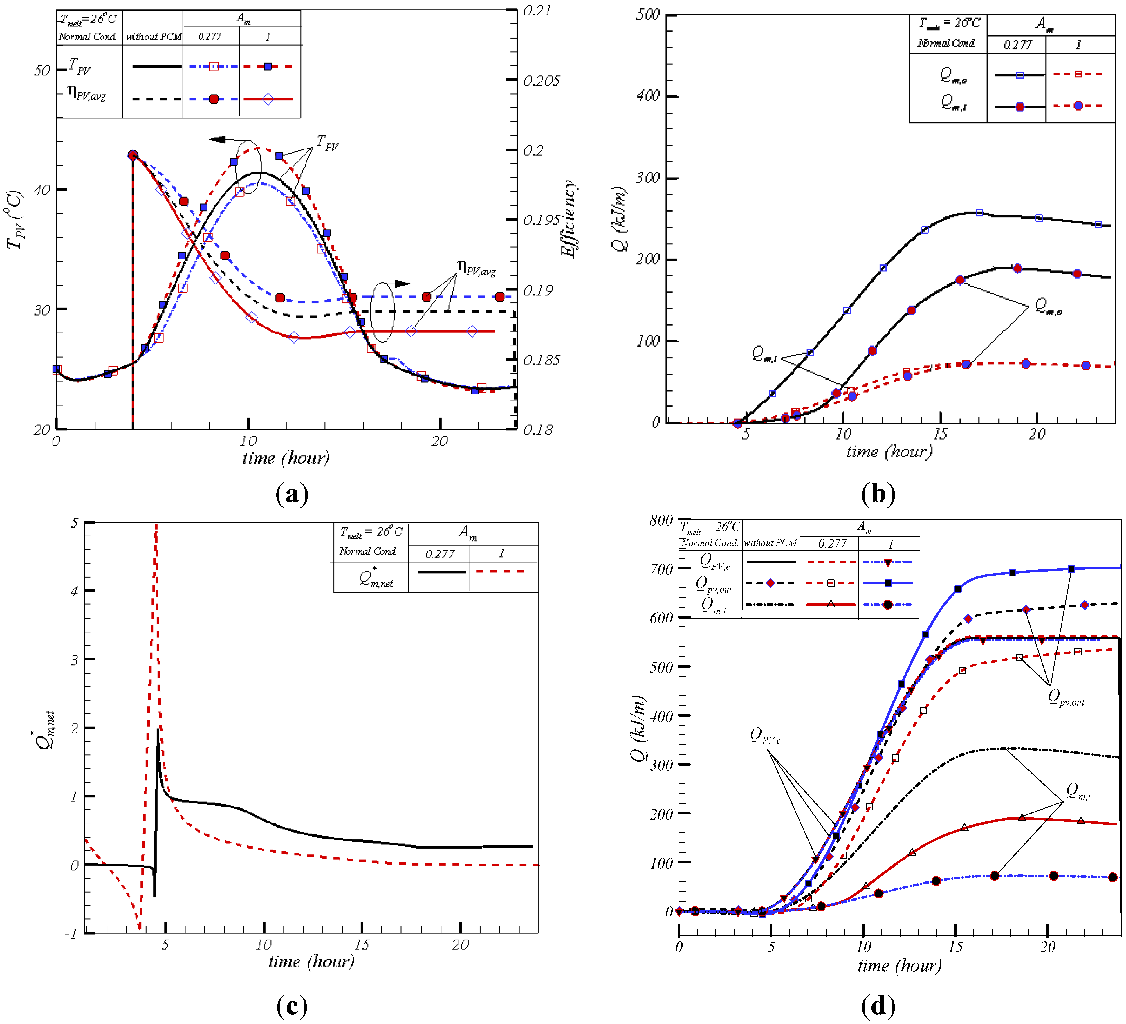
3.1. Aspect Ratio Effect


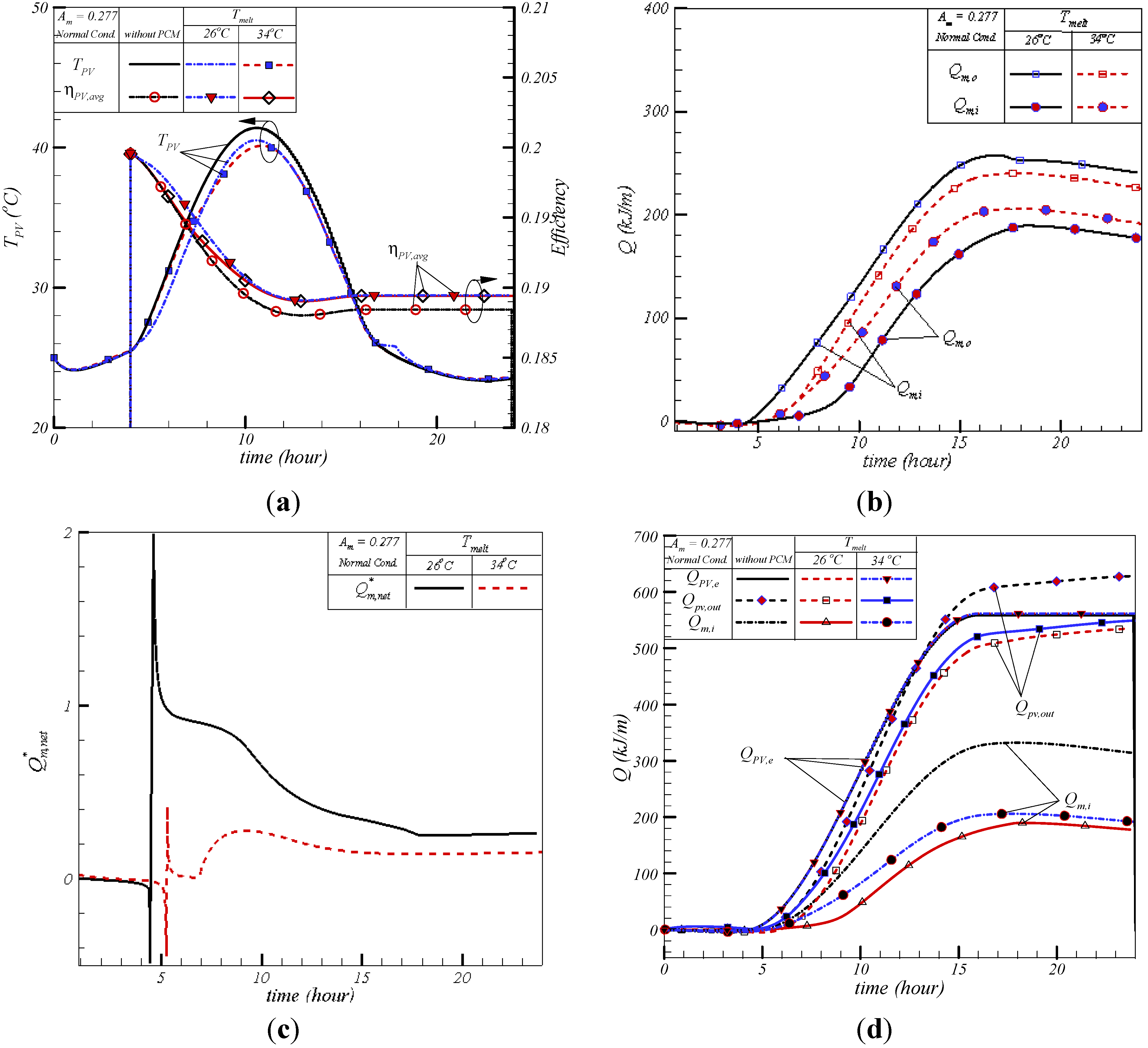
3.2. Melting Temperature Effect

4. Conclusions
Conflict of Interest
Nomenclature
| Am | Aspect ratio (= W/H) |
| Ap | Capsule surface area |
| BIPV | Building-integrated photovoltaic |
| cp | Heat capacity (J kg−1 K−1) |
| CF | Forchheimer coefficient |
| CFD | Computational fluid dynamics |
| dp | MEPCM particle diameter |
| Power output per unit area (W/m2) | |
| g | Gravitational acceleration (m/s2) |
| Gs | Incident solar irradiation (W/m2) |
| h | Heat convection coefficient (W m−2 K−1) |
| H | Height (m) |
| hLS | Latent heat (J/kg) |
| k | Thermal conductivity coefficient (W m−1 K−1) |
| K | Ergun surface constant (m2) |
| L | Length (m) |
| MEPCM | Microencapsulated phase change material |
| P | Pressure (N/m2) |
| PCM | Phase change material |
| PV | Photovoltaic |
| q" | Heat flux (W/m2) |
| q | Heat transfer (W) |
| Q | Energy (J) |
| QUICK | Quadratic upstream interpolation convective kinetics |
| t | Time (s) |
| T | Temperature (°C) |
| u | Dimensionless x-direction velocity (m/s) |
| U | Overall heat transfer coefficient (W m−2 K−1) |
| ∀ | Capsule volume (m3) |
| v | Dimensionless y-direction velocity (m/s) |
| W | Width (m) |
| x | = x+/W |
| y | = y+/H |
Greek letters
| α | Thermal difussivity (m2/s) |
| αr | Absorptivity |
| β | Expansion coefficient |
| βpv | Temperature dependent coefficient |
| βs | Solid expansion coefficient |
| βT,f | Fluid expansion coefficient |
| δ | Thickness (m) |
| ϕ | Porosity |
| η | PV cell efficiency |
| μ | Viscosity (N s/m2) |
| υ | Kinematic viscosity (m2/s) |
| ρ | Density (kg/m3) |
| τt | Delaying coefficient |
| ω | Dimensionless vorticity |
| ω+ | Vorticity |
| ξ | Melt fraction |
| Δ | Difference |
| Ψ | Dimensionless streamline |
| Ψ+ | Streamline |
Subscripts
| avg | Average |
| e | Electricity |
| f | Fluid |
| i | Initial; indoor |
| in | Into the MEPCM |
| M; melt | Melt |
| m | Mixed MEPCM-fluid |
| max | Maximum time |
| o | Outer; reference |
| out | Out of the PV cell |
| p | Particle |
| pv | Photovoltaic cell |
| ref | Reference |
| rise | Sunrise time |
| set | Sunset time |
| s,o | Solar irradiation |
| x | x-axis |
| y | y-axis |
| ∞ | Ambient |
Superscripts
| - | Average |
| * | Dimensionless |
| + | Dimensional |
References
- Meral, M.E.; Dinçer, F. A review of the factors affecting operation and efficiency of photovoltaic based electricity generation systems. Renew. Sustain. Energy Rev. 2011, 15, 2176–2184. [Google Scholar] [CrossRef]
- Joulin, A.; Younsi, Z.; Zalewski, L.; Lassue, S.; Rousse, D.R.; Cavrot, J.P. Experimental and numerical investigation of a phase change material: Thermal-energy storage and release. Appl. Energy 2011, 88, 2454–2462. [Google Scholar] [CrossRef]
- Kuznik, F.; Virgone, J. Experimental assessment of a phase change material for wall building use. Appl. Energy 2009, 86, 2038–2046. [Google Scholar] [CrossRef]
- Borreguero, A.M.; Sanchez, M.L.; Valverde, J.L.; Carmona, M.; Rodriguez, J.F. Thermal testing and numerical simulation of gypsum wallboards incorporated with different PCMs content. Appl. Energy 2011, 88, 930–937. [Google Scholar] [CrossRef]
- Xiao, W.; Wang, X.; Zhang, Y. Analytical optimization of interior PCM for energy storage in a lightweight passive solar room. Appl. Energy 2009, 86, 2013–2018. [Google Scholar] [CrossRef]
- Zhu, N.; Ma, Z.J.; Wang, S.W. Dynamic characteristics and energy performance of buildings using phase change materials: A review. Energy Convers. Manag. 2009, 50, 3169–3181. [Google Scholar] [CrossRef]
- Baetens, R.; Jelle, B.P.; Gustavsen, A. Phase change materials for building applications: A state-of-the art review. Energy Build. 2010, 42, 1361–1368. [Google Scholar] [CrossRef]
- Cabeza, L.F.; Castell, A.; Barreneche, C.; de Gracia, A.; Fernandez, A.I. Materials used as PCM in thermal energy storage in buildings: A review. Renew. Sustain. Energy Rev. 2011, 15, 1675–1695. [Google Scholar] [CrossRef]
- Zhou, D.; Zhao, C.Y.; Tian, Y. Review on thermal energy storage with phase change materials (PCMs) in building applications. Appl. Energy 2012, 92, 593–605. [Google Scholar] [CrossRef]
- Huang, M.J.; Eames, P.C.; Norton, B. Phase change materials for limiting temperature rise in building integrated photovoltaics. Sol. Energy 2006, 80, 1121–1130. [Google Scholar] [CrossRef]
- Maiti, S.; Banerjee, S.; Vyas, K.; Patel, P.; Ghosh, P.K. Self regulation of photovoltaic module temperature in V-trough using a metal-wax composite phase change matrix. Sol. Energy 2011, 85, 1805–1816. [Google Scholar] [CrossRef]
- Lauriat, G.; Prasad, V. Non-darcian effects on natural convection in a vertical porous enclosure. Int. J. Heat Mass Transf. 1989, 32, 2135–2148. [Google Scholar] [CrossRef]
- Ho, C.J. A continuum model for transport phenomena in convective flow of solid-liquid phase change material suspensions. Appl. Math. Model. 2005, 2, 805–817. [Google Scholar] [CrossRef]
© 2013 by the authors; licensee MDPI, Basel, Switzerland. This article is an open access article distributed under the terms and conditions of the Creative Commons Attribution license (http://creativecommons.org/licenses/by/3.0/).
Share and Cite
Tanuwijava, A.O.; Ho, C.J.; Lai, C.-M.; Huang, C.-Y. Numerical Investigation of the Thermal Management Performance of MEPCM Modules for PV Applications. Energies 2013, 6, 3922-3936. https://doi.org/10.3390/en6083922
Tanuwijava AO, Ho CJ, Lai C-M, Huang C-Y. Numerical Investigation of the Thermal Management Performance of MEPCM Modules for PV Applications. Energies. 2013; 6(8):3922-3936. https://doi.org/10.3390/en6083922
Chicago/Turabian StyleTanuwijava, Abednego Oscar, Ching Jenq Ho, Chi-Ming Lai, and Chao-Yang Huang. 2013. "Numerical Investigation of the Thermal Management Performance of MEPCM Modules for PV Applications" Energies 6, no. 8: 3922-3936. https://doi.org/10.3390/en6083922
APA StyleTanuwijava, A. O., Ho, C. J., Lai, C.-M., & Huang, C.-Y. (2013). Numerical Investigation of the Thermal Management Performance of MEPCM Modules for PV Applications. Energies, 6(8), 3922-3936. https://doi.org/10.3390/en6083922