Article

Thermal Efficiency Comparison of Borehole Heat Exchangers with Different Drillhole Diameters

1
GeoZentrum Nordbayern, Friedrich Alexander University Erlangen Nuremberg, Bayern 91054, Germany
2
Rheinland, LGA Bautechnik GmbH, Tillystr. 2, 90431 Nuremberg, Germany
*
Author to whom correspondence should be addressed.
Energies 2013, 6(8), 4187-4206; https://doi.org/10.3390/en6084187
Submission received: 10 May 2013 / Revised: 8 July 2013 / Accepted: 22 July 2013 / Published: 19 August 2013
(This article belongs to the Special Issue Energy Efficient Building Design 2013)

Abstract

:
Thermal efficiency of borehole heat exchangers (BHE) is of crucial importance for the design and optimization of ground source heat pump (GSHP) system. This paper investigates thermal efficiency of a BHE with three drillhole diameters: 121 mm, 165 mm and 180 mm. The BHE was installed in a GSHP system of an office building located in Nuremberg, Germany. Thermal properties and hydraulic properties of the ground where the BHE was installed have been measured by thermal response tests as well as pumping tests. Furthermore, the evaluation of thermal performance is made possible by monitoring operation of the GSHP system. Using the recorded data, thermal exchange rates have been calculated and compared in a daily period as well as a seasonal period. The daily statistics indicate that the thermal exchange rate of the BHE increases with larger drillhole diameter. For the seasonal cooling performance, the amount of thermal exchange of BHE with 165 mm and 180 mm diameters was found to be 3.2% and 7.1% larger than that of the BHE with 121 mm diameter, respectively. These findings provide helpful suggestions for the design of future GSHP systems to achieve higher energy-efficiency.

1. Introduction

Recently, the increasing usage of fossil fuels has been inducing global warming as well as air pollution. Air conditioning of buildings accounts for a large part of the worldwide fossil energy consumption. In order to solve such pending problems, several new energy-efficient solutions have been developed in the last decades. Among all the technologies, ground source heat pump (GSHP) systems have been spotlighted as an efficient energy system due to their great energy savings and CO2 emissions reduction potential. The thermal performance of GSHP system depends heavily on the heat transfer between a borehole heat exchanger (BHE) and its surrounding soil/rock. To ensure high efficiency of GSHP systems, thermal efficiency of the BHE is of essential importance [1,2,3].
Thermal performance of a GSHP system is commonly estimated by in-situ monitoring or by numerical modeling of the BHE. In the last decades, several studies [4,5,6,7,8,9] have been performed to assess the thermal performance of BHEs. These studies have discussed various factors affecting thermal performance such as geometric configuration of the BHE, ground conditions, etc. Pahud and Matthey [10] compared the thermal performance of a double U-tube BHE with different back fillings. Thermal performance was found to be enhanced with increasing thermal conductivity of the back fillings. Similarly, Borinaga-Treviño et al. [11] reported a study concerning the borehole thermal response and thermal resistance of BHE with four different grouting materials. The results indicated that the BHE with a cement-bentonite-graphite based grouting performs better than that of the BHE with cement-based grouting materials. The laboratory-measured grout thermal conductivity was found not to be suitable for borehole resistance estimation due to the increase of contact resistance between pipe and grout during the shrinkage of the cement based mix. Lee et al. [12] investigated the effective thermal conductivity in closed-loop vertical ground heat exchangers. Thermal efficiency was compared for six boreholes constructed with different grouting materials, different configurations as well as different additives. The testing results revealed that cement grouting has a higher effective thermal conductivity than that of bentonite grouting, and graphite performs better than silica. Besides, less thermal interference was found between the inlet and outlet pipe of a new 3-pipe type heat exchanger as compared to the conventional U-tube heat exchanger. Desmedt et al. [13] demonstrated an experimental study of thermal performance of borehole heat exchangers with different grouting materials. Thermal conductivity and borehole resistance were both measured in-situ by TRT tests. The borehole resistance for a standard coaxial tube with a cement-bentonite grouting was measured to be 0.344 K·m/W, whereas this value for a double U-tube was estimated to be 0.162 K·m/W which accounts for 48% of the coaxial tube.
Besides the grouting material, BHE configurations are also important for thermal performance. Zeng et al. [14] proposed an analytical solution considering the impacts of fluid axial convective heat transfer on borehole configurations. Different borehole configurations and flow circuit arrangements in regard to their thermal resistance have been assessed using this method. Results showed that the double U-tube performs better than a single U-tube. However, an opposite conclusion was obtained by Shu et al. [15] during the evaluation of thermal output for single and double U-tube with taken into account the economic performance. Therefore, both thermal and economic performance needs to be considered for an investment of a BHE. Choi et al. [16] investigated the effects of ground water flow on BHE arrays. Three types of BHE arrays have been examined using a two-dimensional numerical model. The results indicated that thermal performance of L-type and single line arrays are noticeably influenced by groundwater flow direction as well as flow rate.
The groundwater flow has also been reported to be an important factor in the thermal performance of BHEs. Wang et al. [17] demonstrated an experimental setup for analysis of the thermal performance of a BHE with consideration of groundwater flow. A model was developed to estimate the groundwater flow characteristics. The results showed that the groundwater flow has obvious impacts on the ground temperature profile in aquifers, which improves the thermal performance of the BHE. Zanchini et al. [18] examined the long-term performance of large borehole heat exchanger fields with unbalanced loads and groundwater flow. Peclet numbers in the range of 0–0.8 were considered in this study. The results show that the hourly peak loads was not affected by groundwater flow. However, the groundwater flow has an obviously influence on the long-term performance. On the other hand, Lazzari et al. [19] investigated the long-term performance of BHE fields with a negligible groundwater movement. The impacts of six time periodic heat loads on different field geometries were studied numerically. The findings indicated that no compensation between winter and summer loads is necessary for a single BHE. For a line of BHEs and for two staggered lines of staggered BHEs, at least a partial compensation of winter heating and summer cooling is needed.
To analyze in depth the thermal performance of a BHE, the short time response of a BHE as well as the thermal interaction between adjacent BHEs also need to be assessed. Lamarche and Beauchmp [20] developed an analytical model for the short time transient response of a BHE. Less than one hour heat transfer of BHE can be simulated using this model. The results from this analytical model follow very well the results from numerical models that take into account the thermal capacity of the borehole. Bernier et al. [21] studied the thermal interaction among boreholes in a geo-exchange system with vertical ground heat exchangers. The results indicated that long-term temperature changes have a significant impact on borehole field sizing and energy simulation results. In addition, the concept of temperature penalty which represents an effective increase of the undisturbed ground temperature was used for evaluation of borehole thermal interactions. A correlation was proposed to predict the temperature penalty and it provided results within an uncertainty of ±10% for most operation conditions.
However, the aforementioned studies were limited to small scales such as laboratory measurements and site tests. Some of them examined the thermal exchange in the BHE only based on numerical simulation. In this work, a more thorough study of thermal efficiency of BHE is conducted under practical GSHP system operation conditions. An analysis of the thermal efficiency of the BHE has been conducted on a GSHP system installed in an office building located in Nuremberg, Germany. The BHE with three drillhole diameters were installed in the GSHP system. The thermal performance is analyzed using the monitoring data accumulated under operation of the GSHP system. Thermal exchange between the BHE and its surrounding soil/rock is measured and analyzed. The remaining sections of this paper are organized as follows: Section 2 presents the ground properties measurement and the system configuration. Section 3 describes the measured data and analyzes the thermal performance of BHE under different diametric conditions. Finally, the article concludes with a summary of the results of this study in Section 4.

2. Experimental Measurements

2.1. Ground Properties Measurement

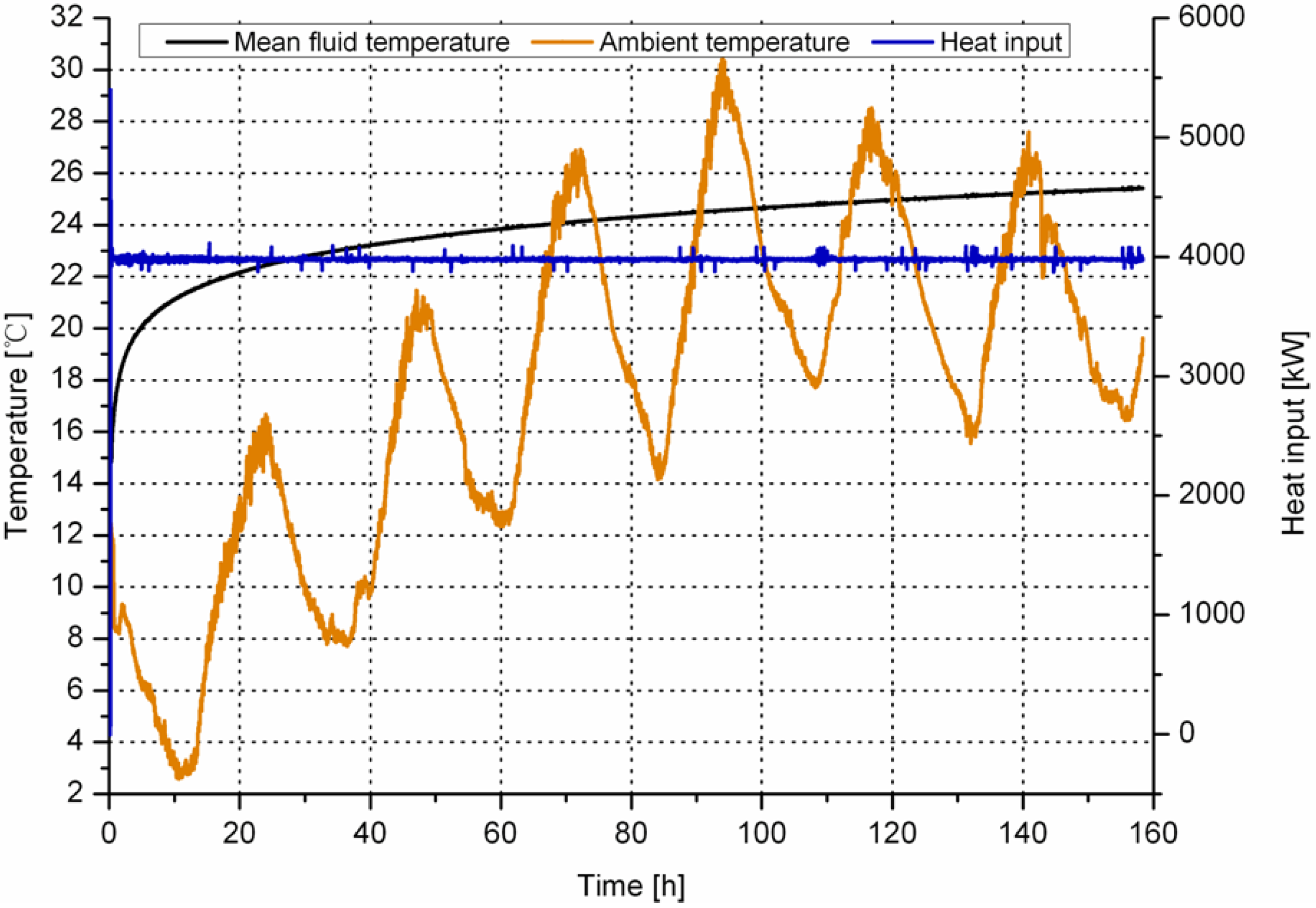
2.1.1. Thermal Properties

Thermal properties of the ground where the BHE was installed have been measured by performing thermal response tests (TRT). For a TRT test, a defined heat load is input in the circulating heat carrier fluid and the resulting temperature changes are measured [22]. Figure 1 shows the recording of the TRT test performed for the drillhole of 121 mm diameter [23]. It is observed that the fluid temperature keeps increasing with testing time. Heat input remains almost constant during the whole testing period, except for a few minutes in the beginning of the tests. At the same time, the ambient temperature was observed to change abruptly, ranging from 3 °C to 30 °C during the 7-day testing period. These findings imply that the abrupt change in ambient temperature is an important factor affecting the testing results.
Figure 1. Recording of the TRT test performed in the drillhole of 121 mm diameter. The TRT tests have been performed separately at the three ensembles of the installed BHEs.
Energies 06 04187 g001
The TRT measurements were interpreted by following Hellström’s method [24]. In this method, the heat transfer of a BHE in the ground is described by two parameters: effective thermal conductivity which describes the mean thermal conductivity of the surroundings for borehole, λeff; and borehole resistance which describes heat transfer between pipes and borehole wall, Rb. A steady-state heat transfer calculations gives a heat flow Q, between circulating fluid and borehole wall. Then, the heat transfer in a BHE can be derived as follows:
T f = Q 4 π λ e f f H ln ( t ) + Q H { 1 4 π λ e f f [ ln ( 4 a r 0 2 ) γ ] + R b } + T s
where m is the inclination of the curve of temperature versus logarithmic time, to calculate effective thermal conductivity; λeff, the formula has to be transformed:
λ e f f = q 4 π H m
In the first few hours, the temperature development is mainly controlled by the borehole filling and not by the surrounding soil or rock. Therefore, the minimum duration criterion should be noted. The minimum time for valid evaluation of the test is recommended as:
t > 5 r 2 α
The measured thermal conductivities for the three different drillhole diameters match nicely, which means average thermal conductivity along the borehole is around 2.5–2.6 W/m/K, as summarized in Table 1. Besides, drillhole diameter has an effect on the Rb, with bigger diameters yielding higher resistance. Similar findings were obtained by Smith and Perry [7] for tests conducted on BHEs using different grouts and varying pipe and drillhole diameters.
Table 1. Results obtained from the performed three TRT tests.
Drillhole diameterλ (W/m/K)Rb (m*K/W)
121 mm2.50.093
165 mm2.60.105
180 mm2.60.110

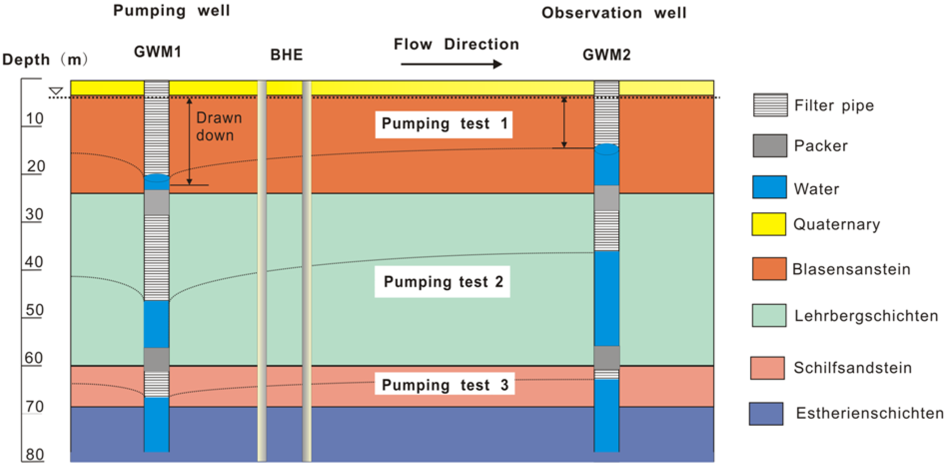
2.1.2. Hydraulic Properties

To measure hydraulic properties, pumping tests have been performed. In order to perform the pumping tests, two investigation wells have been drilled with a depth of 80 m. One of the wells, the upstream, was named as groundwater measurement point one (GWM 1). The other one which located at the downstream was named as groundwater measurement point two (GWM 2).
According to the material types, the pumping tests have been performed in three different geological layers (Figure 2). Packers were used at each boundary between different layers to separate the tests. Thiem’s method was used for interpretation of the horizontal pumping tests. In cases of that only one observation well at a distance, r, from the pumping well is available, the well discharge can be formulated as:
W = 2 π K D ( s w s 1 ) ln ( r 1 / r w )
where, sw and s1 are the respective steady-state elevations of the water levels in the piezometers; r1 is the distance between pumping well and observation well; rw is the radius of the pumping well [24].
Figure 2. Schematic diagram of the pumping tests, the horizontal hydraulic properties of the geological layers have been investigated.
Energies 06 04187 g002
Hydraulic properties of the geological layers calculated using Thiem’s method are listed in Table 2. The hydraulic conductivity of the “Blasensanstein” layer consisting of sandstone shows the biggest value of 1.71−5 m/s. That of the middle “Lehrbergschichten” layer which interbeds sandstone and claystone is determined to be 1.27−5 m/s. The hydraulic conductivity of the “Schilfsandstein” layer consisting of sandstone is measured to be 9.8−6 m/s. Furthermore, a permeability test was conducted to measure detailed material parameters of the layers. The hydraulic conductivity of the “Estherienschichten” layer that consists of claystone is measured to be 6.74−9 m/s. Therefore, this layer is treated as an aquiclude.
Table 2. The hydraulic properties estimated by pumping tests and permeability tests.
Geological layerMaterial typeDepth (m)Transmissivity (m2/s)Hydraulic conductivity (m/s)
Quaternarysand0–4--
Blasensansteinsandstone4–253.4−41.71−5
LehrbergschichtenSandstone, claystone26–553.8−41.27−5
Schilfsandsteinsandstone56–626.88−59.8−6
Estherienschichtenclaystone62–80-6.74−9

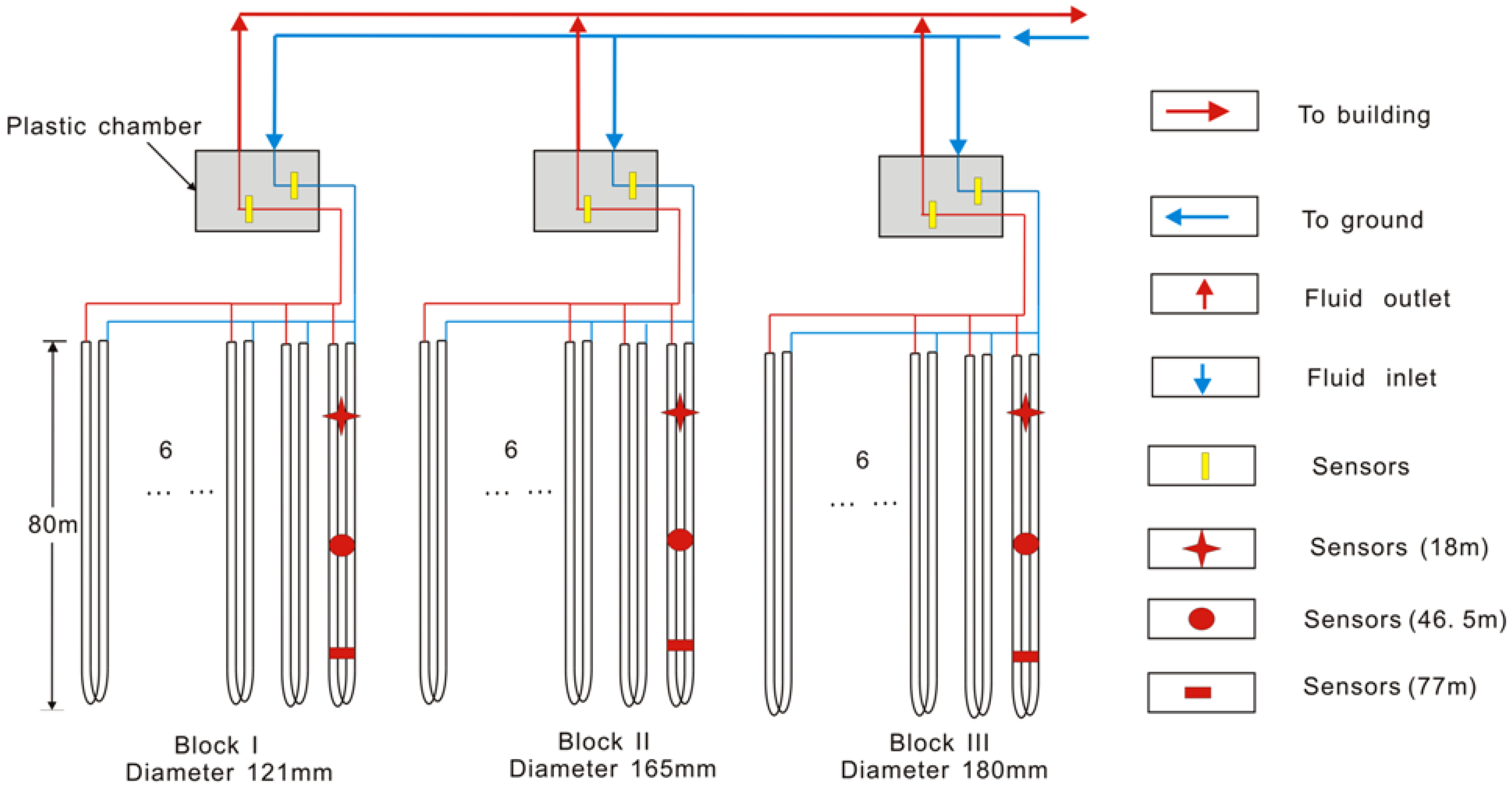
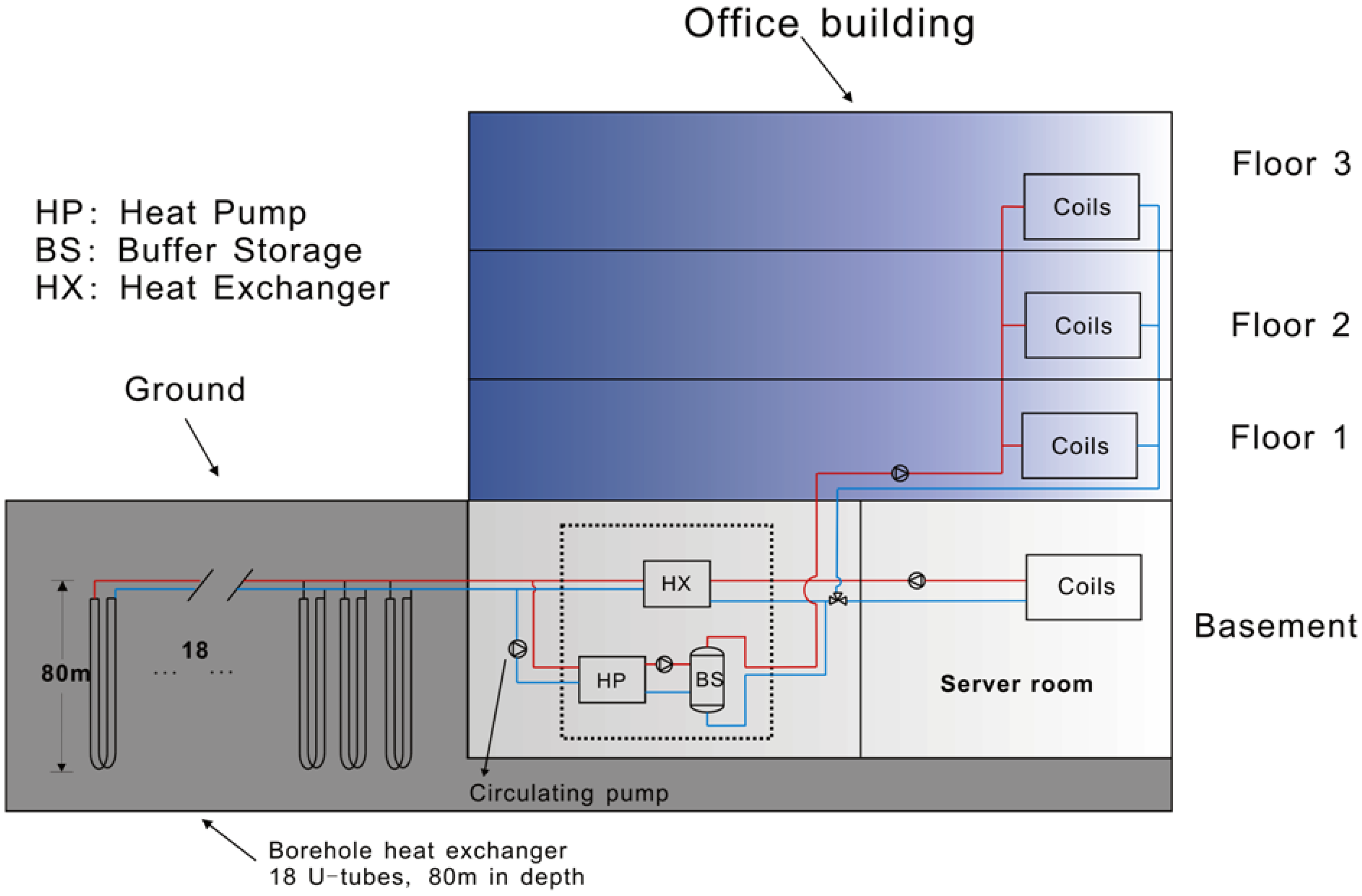
2.1.3. System Configuration

In order to investigate the thermal efficiency, in this study, the BHE was designed with three drillhole diameters using a commercial computer program Earth Energy Design (EED) [25]. By coupling into a GSHP system of an office building in Nuremberg city of Germany, the BHE was used for space heating as well as cooling. The office building, constructed in 2008, has three floors and one basement with a total area of 1530 m2. The GSHP system was finished the installation works and started operation in 2009.
A schematic diagram of the installed GSHP system is depicted in Figure 3. Briefly, the GSHP system consists of a BHE, water-to-refrigerant heat exchanger and indoor units. The BHE was constructed with 18 boreholes that can be classified into blocks according to the drillhole diameter: block I of 121 mm, block II of 165 mm and block III of 180 mm, as shown in Figure 4. Geometrically, the BHE was a 2 × 9 array with a distance of 6 m between adjacent drillholes. In summer, the system operates in cooling mode and the heat obtained from the building is dissipated to ground. Whereas, in winter the GSHP system extracts heat from the ground to warm up the conditioned space using heat pump (SWP 75 I, Uponor GmbH, Hassfurt, Germany). The operation of this GSHP system either in heating mode or in cooling mode was controlled by a three-way valve.
The connection between the BHE and indoor units are the heat pump and the plate heat exchanger. The usage of the heat pump and the plate heat exchanger depends on the system operation mode. In winter, the system operates in heating mode and the heat pump is used for space heating. On the other hand, in summer, the system runs in cooling mode. A metal plate with a high thermal conductivity is used for transfer the energy from the fluid circulating in U-tube to the building. These components and a computer server were installed in the basement, covering an area of 380 m2. The functional area of the building (offices, meeting rooms, corridors) are located in the three above-ground floors, covering a total air-conditioned zone of 1150 m2. Coils were embedded into the floors and heat radiators were installed in the rooms to meet different temperature requirements (i.e. coils were designed to keep a constant temperature of 21 °C, heat radiators is 25 °C). The operation mode of the GSHP system depends on the actual energy demand of the building.
Figure 3. Schematic diagram of the GSHP system with vertical double U-tube BHEs. The BHEs of this GSHP system are in parallel connection.
Energies 06 04187 g003
Figure 4. Schematic cross-section of the installed three-block BHEs. The temperature sensors were installed at the center of the BHEs and they are separately located at 18 m, 46.5 m and 77 m below the ground surface.
Energies 06 04187 g004
The sensors for measuring the subterranean borehole temperature are separately installed at 18 m, 46.5 m and 77 m below the ground surface. To keep the sensors at the same position, the cross-section center of the BHE, plastic holders were used. These holders with a hollow center were connected with four U-tube legs and the temperature sensors were installed in the hollow to measure the underground borehole temperature.
The specifications of the BHE components, containing configuration parameters and material properties are summarized in Table 3. It is observed that the geometric configurations of the three BHEs have the same inner configurations, but with different outer diameters. High density polyethylene double U-pipe was selected as the borehole heat exchanger. The space between the double U-pipe and the ground was grouted using enhanced cement with a thermal conductivity of 2.35 W/m/K. Glycol-based refrigerant media is circulated through the polyethylene pipe by water circulating pumps (TOP-S65/13, WILO AG, Dortmund, Germany). The properties of the grouting material are obtained from the products specifications.
Table 3. Geometric configurations and material properties for the BHE.
ComponentsParametersSpecification
BHE configurationsBoreholeBorehole depth: 80 m
Borehole distance: 6 m
Drillhole diameter: 121 mm, 165 mm and 180 mm
U-PipePipe type: Double-U
Pipe shank spacing: 70 mm
Pipe outer diameter: 32 mm
Pipe wall thickness: 3 mm
BHE propertiesGroutsGrouting thermal conductivity: 2.35 W/m/K
Volumetric water content: 31%
Grouting density: 1.8 g/cm3
U-pipePipe thermal conductivity: 0.42 W/m/K
Fluid propertiesHeat carrier fluidFluid density: 1.11 g/cm3
Fluid volumetric thermal capacity: 3.8 MJ/m3/K

2.2. Measurements Setup

Monitoring System

In order to investigate thermal efficiency of the BHE with different drillhole diameters, in this study, the measurements were conducted separately on each of the three BHEs. The temperature sensors (TST90, Endress + Hauser Messtechnik GmbH + Co. KG, Freiburg, Germany) were installed to measure fluid inlet and outlet temperature. At the same time, flow meters (Promag 53P40, Endress + Hauser Messtechnik GmbH + Co. KG) were installed to monitor flow rate of the fluid circulating through the U-pipes. Figure 5 shows schematic diagram of the measurement setup. It can be seen that the pipes for each six BHEs that have the same drillhole diameter were assembled into a chamber. The sensors were installed inside the chambers to monitor the fluid. Consequently, the fluid temperature and flow rate had been monitored separately for each drillhole diameter.
The specifications of these sensors, together with their models and measuring accuracy are listed in Table 4. The operating conditions of the GSHP system can then be monitored using these sensors. More specifically, the installation position of the sensors is also mentioned in this Table. The detailed installations of these sensors are depicted in Figure 4, Figure 5 and Figure 6.
Figure 6 shows a snapshot of the measurement setup on site with a view of internal settings of the plastic chamber. Two manifolds were installed for each plastic chamber, the lower one was for the fluid circulating to ground and the upper one was for the fluid circulating to the building. Pipes of the BHE were separately assembled for fluid inlet and outlet, which indicate that each six BHEs are parallelly connected. Therefore, the flow rate was evenly distributed due to the same pressure distribution of each pipe. In addition, outdoor temperature was also monitored using the sensor (TST434, Endress+Hauser Messtechnik GmbH + Co. KG). Then, thermal performance under different environmental conditions was analyzed. All the information regarding temperature, flow rate and the energy budget were continuously recorded by a data acquisition system. These parameters, together with the date and the time of the day, were also stored every 10 min.
Figure 5. Schematic diagram of the measurement setup. The temperature sensors were separately installed at each block to measure the U-tube fluid in-outlet. There are twelve sensors, containing six temperature sensors and six flow meters. In addition, the temperature sensors were also installed inside the BHEs with different depths: 18 m, 46.5 m and 77 m. We select one of the sensors which have the same position in each block to measure the subterranean borehole temperature.
Energies 06 04187 g005
Table 4. The installed temperature sensors and flow meters [26].
Monitoring parameterComponentsSpecification
Subsurface borehole temperaturePT-100 temperature sensorsManufacture: Endress + Hauser Messtechnik GmbH + Co. KG
Model: TST434
Measure range: −50–100 °C
Uncertainty: ±0.05 °C
Located at depth: 18 m, 46.5 m and 77 m
In-outlet fluid temperaturePT-100 temperature sensorsManufacture: Endress + Hauser Messtechnik GmbH + Co. KG
Model: TST90
Measure range: −50–200 °C
Uncertainty: ±0.05 °C
Located at fluid inlet/outlet of U-tube
Flow rateFlow meterManufacture: Endress + Hauser Messtechnik GmbH + Co. KG
Model: Promag 53P40, DN40 1 1/2”
Assists energy: voltage 85–260 V
Measure range: 0 dm3/min–200 dm3/min
Uncertainty: ±0.2%
Located at fluid inlet/outlet of U-tube
Energy budgetData loggerManufacture: Endress + Hauser Messtechnik GmbH + Co. KG
Model: Memograph M RSG40
The results are stored every 500 microseconds
Figure 6. A snapshot of the measurements onsite. Two manifolds were installed, the lower one was for the fluid circulating to ground and the upper one was for the fluid circulating to the building. The marked 1, 2, 3, 4, 5 and 6 are for fluid circulate to the building; I, II, III, IV, V and VI are fluid circulate to the ground.
Energies 06 04187 g006
Based on the measurements, the energy exchanged between the BHE and the surrounding soil/rock at two successive entries of data logging can be calculated as:
E = q ρ c m ( T o T i )
where E is the thermal exchange rate (kW); q is the flow rate (m3/h); ρ is the fluid density (g/cm3); Ti is the fluid inlet temperature (°C) and To is the outlet temperature (°C) [26]. The instantaneous (500 microsecond interval) heat supplied to the building was calculated by Equation (1) and the mean values with every 10min interval were stored. These values of thermal load can be positive or negative. Conventionally, the heat supplied to the building is considered to be positive.

3. Results and Discussion

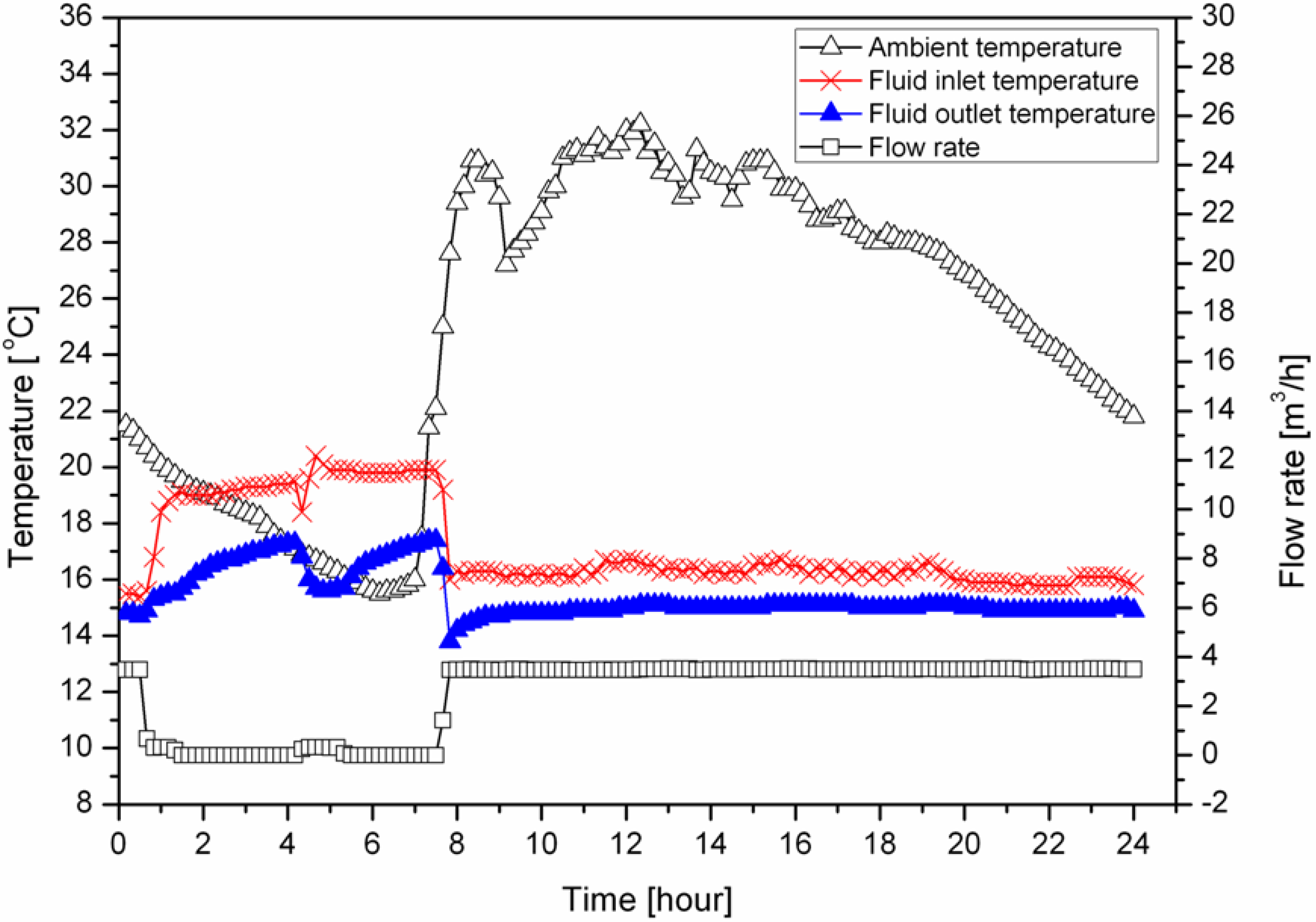
3.1. Typical Daily Operation

We selected August 07, which was a typical summer day, to investigate operation of the GSHP system in cooling mode. Figure 7 shows the ambient temperature, fluid temperature at inlet/outlet of the ground and the corresponding flow rate in that day. The fluid inlet temperature was higher than the fluid outlet temperature, which indicates that the ground was heated by the energy removed from the building. The flow rate of the circulating fluid maintains zero when the ambient temperature dropped to 20 °C. During this period, between 01:00 AM and 09:00 AM, the GSHP system stopped operation and the fluid temperatures (inlet and outlet) were found to increase obviously. This can be attributed to the heat conduction between the circulating fluid and its surroundings at the position of BHE top where with a depth of 1.0 m. At such a depth, the soil was heated by the solar radiation during the daytime and this resulted in a high ground temperature. Therefore, the fluid inlet/outlet temperature measured at the top of the BHE was observed to increase. On the other hand, when the GSHP system was operating, the fluid temperature was almost constant, regardless of any abrupt changes in ambient temperature. The fluid inlet-outlet temperature difference was maintained at 1 °C. This fact implies that the GSHP system has a stable cooling performance in summer.
Figure 7. Recording of the GSHP system operation in a typical summer day (August 07, 2009).
Energies 06 04187 g007
Figure 8 represents the operation conditions of the GSHP system in heating mode. The measurements were conducted on December 27, a typical winter day with the ambient temperature varying from −4 °C to 4 °C. The fluid inlet temperature is lower than the fluid outlet temperature, indicating that the ground was used as a “heat source”. It is observed that the flow rate of the heat carrier fluid fluctuates frequently between zero and 4 m3/h. At the same time, the fluid temperature fluctuates as well. Those fluctuations can be easily explained by the operation of the heat pump. In winter, the heat pump operated to extract energy from the heat carrier fluid and the fluid temperature then reduced sharply. Due to the higher ground temperature the fluid temperature can be recovered rapidly when the heat pump stopped operation. Consequently, the fluid temperature and flow rate fluctuated as observed. This finding indicates that electricity consumption of the building can also be fluctuated due to the aforementioned operation of the heat pump.
Figure 8. Recording of the GSHP system operation in a typical winter day (December 27, 2009).
Energies 06 04187 g008

3.2. Comparison of Experimental Condition

In order to compare the experimental conditions, the fluid inlet temperature of the three blocks BHEs was investigated. Figure 9 represents the hourly fluid inlet temperature measured on August 07, a typical summer day. Minor difference of fluid temperature was found in the three investigated BHEs, except for the period between 01:00 AM and 08:00 AM. During this period, as shown in Figure 7, the GSHP system was shut down. The noticeable differentiation in fluid temperature was therefore caused by the heat conduction between soil and static fluid in the pipe as aforementioned in typical daily operation. To evaluate the deviations of the three blocks, the fluid inlet temperature was compared during the system operation. The fluid temperature differences of the investigated three blocks are quite small, within 0.1 °C. Considering that the measurement uncertainties of the temperature are ±0.05 °C, such a small difference can then be considered negligible.
On the other hand, the fluid inlet temperature was also investigated on a typical winter day. Figure 10 shows the hourly fluid inlet temperature profile on December 27, 2009. The fluid inlet temperature was observed to drop severely at the BHE of 121 mm diameter when compared to the other two blocks (block II and block III) which have a negligible difference in the fluid inlet temperature. As shown in Figure 5, the BHE of 121 mm diameter have the largest distance to the building, whereas, block II and block III have similar distances that are both smaller than that of the 121 mm diameter BHE. Considering the intermittent operation of GSHP system and the ground cooled by the chilly weather in winter, as aforementioned in Figure 8, the serious temperature drop can be well explained by heat dispersion to the ground due to the lower temperature of the surrounding soil. This finding indicates a large amount of energy loss in the horizontal pipe during winter day system operation. To achieve higher energy-efficiency, the energy loss in the horizontal pipe needs to be seriously considered in future GSHP system design and implementation in cold regions. Meanwhile, the unevenly distributed fluid inlet temperature in three BHEs ensembles suggests also that comparison of thermal performance using the data collected from winter days may deviate. Therefore, the thermal efficiency comparison, in this paper, is conducted using only the data collected during the GSHP system in cooling mode to ensure higher accuracy.
Figure 9. Hourly fluid inlet temperature distribution of the three investigated three blocks BHEs on August 07, 2009.
Energies 06 04187 g009
Figure 10. Hourly fluid-inlet temperature distribution of the three investigated BHEs at December 27, 2009.
Energies 06 04187 g010

3.3. Comparison of Thermal Efficiency

To compare thermal efficiency more accurately, this study is solely based on data of the GSHP system operating in heating mode in 2009, the beginning of operation of the GSHP system. The data collection started from July till the end of that year. The thermal performance is estimated considering the amount of thermal exchange which can be calculated with Equation (5). Based on the thermal exchange, the thermal efficiency can then be compared as follows:
R i = E i E 121 E 121 × 100 %
where R is the thermal comparison ratio (%); E is the amount of thermal exchange (kWh); and the subscript i is the object that need to be compared with the BHE with a diameter of 121 mm.
Figure 11 represents the comparison results obtained using the data measured on August 07, 2009. These measurements were only conducted while the GSHP system was in operation from 10:00 AM to 05:00 PM on that day. The comparison of the thermal efficiency shows that the BHE of 180 mm diameter has the best thermal performance. On average, the daily amount of thermal exchange in the BHE of 180 mm diameter was calculated to be 6.7% larger than that the BHE of 121 mm diameter. The maximum difference between the 121 mm and 180 mm diameters BHEs was 10% in that day. For the comparison of BHE of 165 mm diameter and 121 mm diameter, the daily average ratio drops down to 2.16%, accounting for 54% of the daily maximum value (4.0%). These results indicate that increase the drillhole diameter will slightly improve the thermal performance of BHE despite the fact that the thermal conductivity of grouting material (2.35 W/m/K) is smaller than that of the ground (2.5 W/m/K).
Figure 11. Thermal efficiency comparison of the BHE with three different drillholes on August 07, 2009. The thermal comparison ratio is presented for block II and block III as compared to block I.
Energies 06 04187 g011
Another fact regarding the GSHP system operation is revealed in Figure 12. As it can be seen, monthly thermal loads for the BHEs against ambient temperature are presented separately. Thermal loads of the three blocks of BHEs show an obvious increasing trend. Like the daily investigation, thermal performance of the BHE increases for larger drillhole diameter. At the same time, the thermal load of the BHEs is observed to strongly correlate with the ambient temperature. With higher ambient temperature, the cooling load increases as well.
Figure 12. Monthly cooling load between July, 2009 and December, 2009.
Energies 06 04187 g012
Figure 13 shows the investigated thermal comparison ratio and the subterranean borehole temperature. The subterranean borehole temperature, in this work, was measured in the middle of the BHE, as shown in Figure 4. The mean value of the temperature measured at three depths is used due to the fact there is a negligible difference among these three depths. It is noticed that the difference of cooling performance for the BHE with different diameters is negligible when the subterranean borehole temperature reaches up to 12.5 °C.
Figure 13. Thermal efficiency comparison of the BHE under different subterranean borehole temperature.
Energies 06 04187 g013
When the subterranean borehole temperature drops down to 11 °C, the difference becomes substantial. Even more, this difference will be several times larger when the subterranean borehole temperatures are lower than 10 °C. These findings suggest that thermal efficiency of the BHE with different diameters depends heavily on the subterranean borehole temperature. With a lower subterranean borehole temperature yields a higher cooling performance of the BHE with a bigger diameter.
In the long run, the thermal efficiency of the BHEs was estimated by calculating the seasonal cooling performance. Figure 14 represents the seasonal amount of thermal exchange between the BHE and its surroundings. The results show an ascending trend of the amounts of heat with increased drillhole diameter. Comparing the three BHE ensembles, the amount of seasonal thermal exchange for the BHE of 165 mm and 180 mm diameter is 3.2% and 7.1% larger than that of 121 mm diameter, respectively.
Figure 14. Comparison of seasonal thermal efficiency of BHE with different drillhole diameters.
Energies 06 04187 g014

4. Conclusions

In this paper, the thermal performance of a borehole heat exchanger (BHE) was investigated for three different drillhole diameters. This study was conducted by monitoring the operation of the GSHP system in 2009. The daily GSHP system operation was discussed separately for heating mode and cooling mode. In addition, the impacts of ambient temperature and subterranean borehole temperature on thermal performance were also analyzed. Finally, the seasonal thermal efficiency of the BHE was compared and discussed. Major conclusions are as follows:
  • Thermal properties of the ground where the BHE was installed were measured by thermal response (TRT) tests. The effective thermal conductivity of the ground with a depth of 80 m was measured to be 2.5–2.6 W/m/K. This value is bigger than that of the grouting material with a thermal conductivity of 2.35 W/m/K. During performing the TRT tests, the ambient temperature was found to be an important factor to influence the testing results. Therefore, the connection pipes for a TRT test need to be carefully insulated. In addition, the hydraulic properties of the geological layers were measured by pumping tests. Based on the measurements, the geological layers were classified into different hydraulic units;
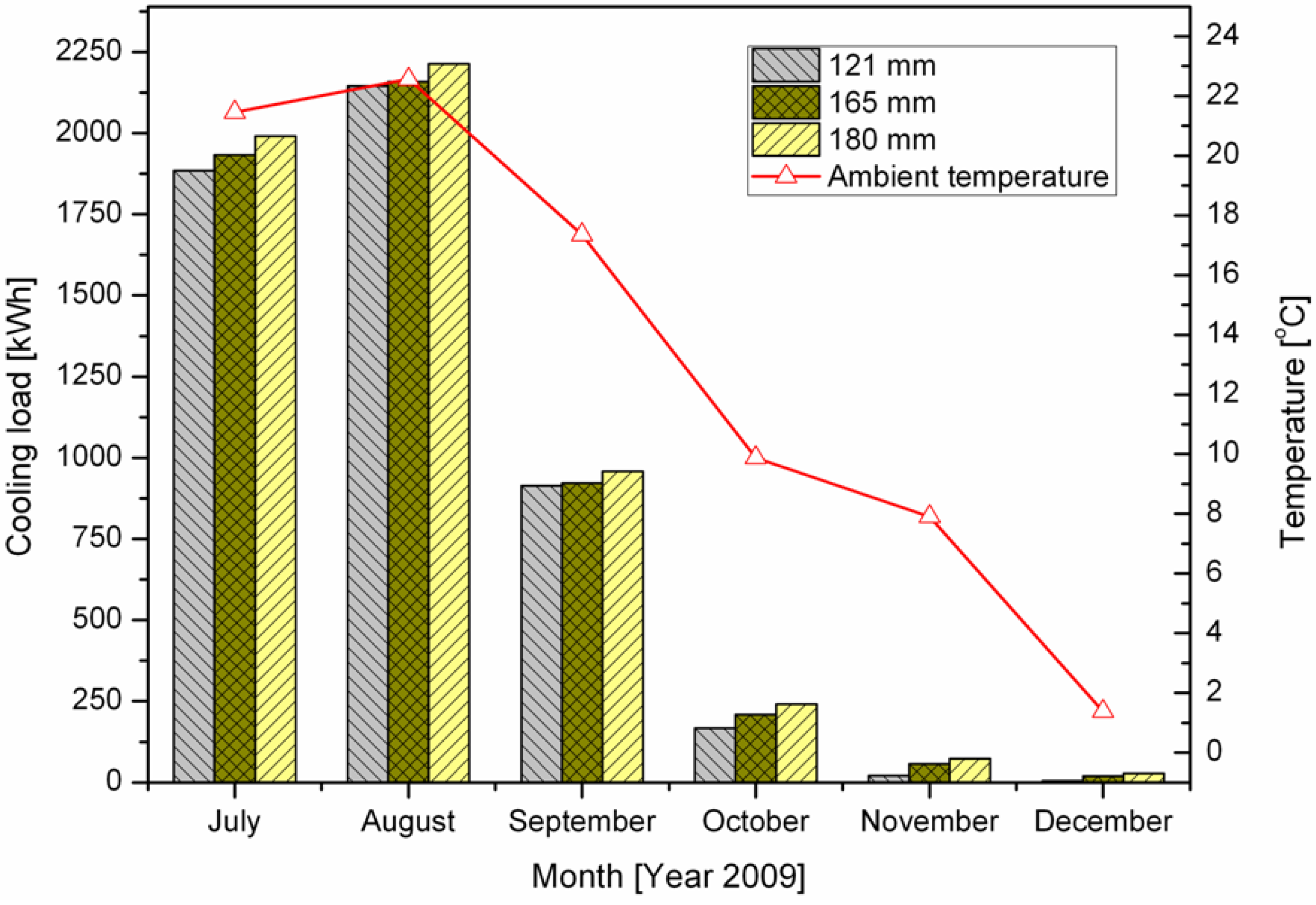
  • The GSHP system was investigated for both a typical winter day and summer day. On a typical summer day, the GSHP system operates in cooling mode. On that day, the GSHP system delivers a stable cooling performance due to the constant fluid temperature and flow rate. On a typical winter day the heat pump operates to extract the energy from the heat carrier fluid, which abruptly changes the fluid temperature. Conclusively, the fluid temperature and flow rate fluctuate with time;
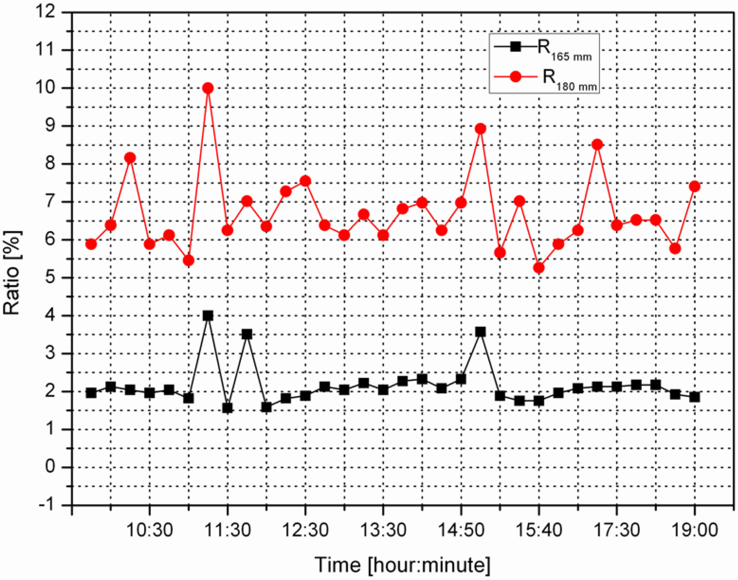
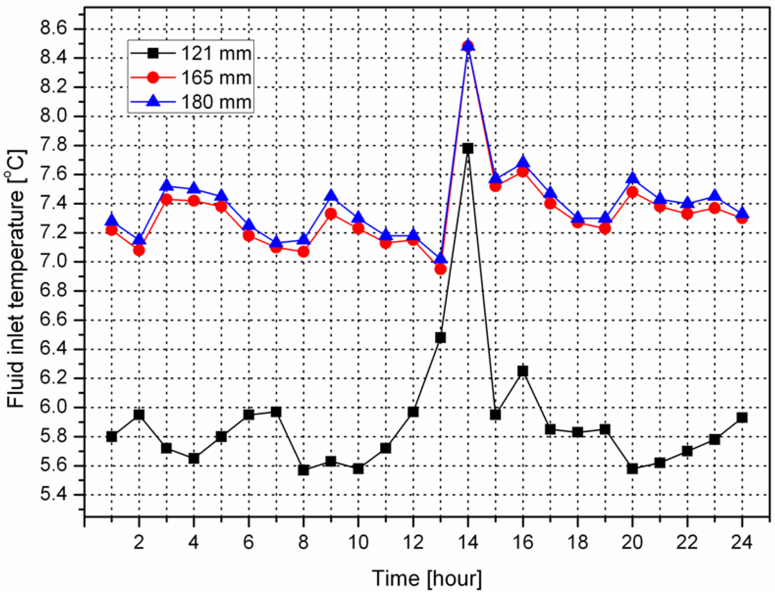
  • In order to ensure the same experimental conditions, the fluid inlet temperature was investigated. Only negligible differences of the fluid inlet temperature were found in the three BHE blocks. However, an obvious fluid temperature drop was observed when the fluid circulates in the horizontal pipe in winter. This fluid temperature drop needs to be seriously considered in future GSHP system design and implementation in cold regions. As a result, the comparison of thermal efficiency was conducted using only the data collected during summer;
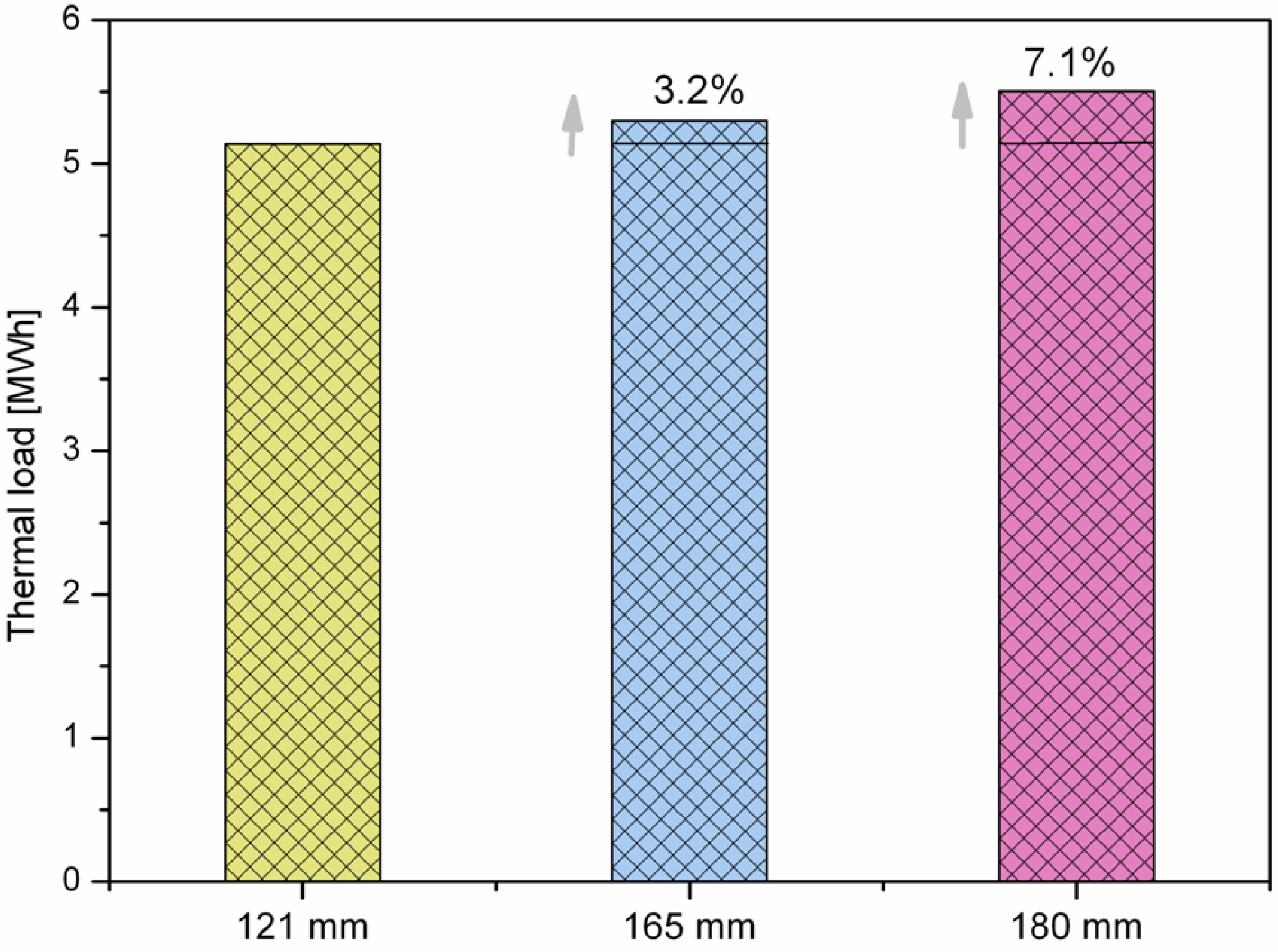
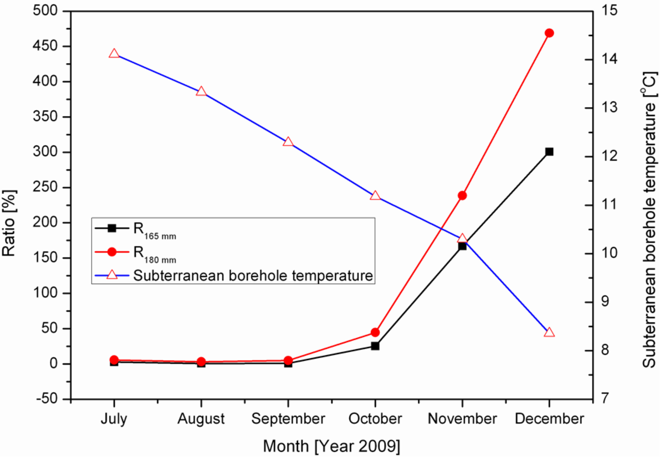
  • The comparison of the daily thermal efficiency suggested that the BHE with a bigger drillhole diameter has a better thermal performance, despite the fact that the grouts have a lower thermal conductivity as compared to the ground. The investigated daily performance between 180 mm and 121 mm diameter is 6.7%, whereas this value drops to 2.16% between 165 mm and 121 mm diameter on a typical summer day. In addition, the difference of cooling performance among the three drillhole diameters depends heavily on the subterranean borehole temperature. A lower the subterranean borehole temperature yields a higher BHE cooling performance with a bigger drillhole diameter. In the long run, the amount of seasonal thermal exchange for the BHE of 165 mm and 180 mm diameter is 3.2% and 7.1% larger than that of 121 mm diameter, respectively.

Nomenclature:

T
temperature (°C)
R
thermal resistance (W/m/K)
r
borehole radius (m)
Q
heat rate (kW)
W
pumping rate (m3)
H
borehole length (m)
q
thermal transfer rate (W/m)
E
thermal load (kWh)
C
specific thermal capacity (J/kg/K)
s
water head (m)
KD
hydraulic tansmissivity

Greek Symbols:

ρ
density (g/cm3)
λ
thermal conductivity (W/m/K)

Subscripts:

i
inlet flow
o
outlet flow
f
fluid
s
ground surrounding
eff
effective
b
borehole
w
water

Acknowledgements

This work is financed by Bayerisches Staatsministerium für Umwelt und Gesundheit. Sincere thanks are due to the Bayerische Forschung Stiftung (BFS) for providing a scholarship. The authors would also like to thank for the support provided by the Ochs Company (Nuremberg, Germany). We acknowledge support by the Deutsche Forschungsgemeinschaft and Friedrich-Alexander-Universität Erlangen-Nürnberg within the Open Access Publishing funding programme.

References

  1. Michopoulos, A.; Bozis, D.; Kikidis, P.; Papakostas, K.; Kyriakis, N.A. Three-years operation experience of a ground source heat pump system in Northern Greece. Energy Build. 2007, 39, 328–334. [Google Scholar] [CrossRef]
  2. Yang, H.; Cui, P.; Fang, Z.H. Vertical-borehole ground-coupled heat pumps: A review of models and systems. Appl. Energy 2010, 87, 16–27. [Google Scholar] [CrossRef]
  3. Bose, J.; Smith, M.D.; Spiter, J.D. Advances in Ground Source Heat Pump Systems—An International Overview. In Proceedings of the 7th International Energy Agency Heat Pump Conference, Beijing, China, 19–22 May 2002; pp. 313–324.
  4. Gehlin, S. Thermal Response Test: In Situ Measurements of Thermal Properties in Hard Rock. Master’s Thesis, Lulea University of Technology, Lulea, Sweden, 1998. [Google Scholar]
  5. Teza, G.; Galgaro, A.; De, C.M. Long-term performance of an irregular shaped borehole heat exchanger system: Analysis of real pattern and regular grid approximation. Geothermics 2012, 45–56. [Google Scholar] [CrossRef]
  6. Hwang, Y.J.; Lee, J.K.; Jeong, Y.M.; Koo, K.M.; Lee, D.H.; Kim, I.K.; Kim, I.K.; Jin, S.W.; Kim, S.H. Cooling performance of a vertical ground-coupled heat pump system installed in a school building. Renew. Energy 2009, 34, 578–582. [Google Scholar] [CrossRef]
  7. Smith, M.D.; Perry, R.L. Borehole grouting: Field studies and thermal performance testing. ASHRAE Trans. 1999, 105, 451–457. [Google Scholar]
  8. Borinaga-Treviño, R.; Pascual-Muñoz, P.; Castro-Fresno, D.; Del Coz-Díaz, J.J. Study of different grouting materials used in vertical geothermal closed loop heat exchangers. Appl. Therm. Eng. 2012, 50, 159–167. [Google Scholar] [CrossRef]
  9. Philippacopoulos, A.J.; Berndt, M.L. Influence of debonding in ground heat exchangers used with geothermal heat pumps. Geothermics 2001, 30, 527–45. [Google Scholar] [CrossRef]
  10. Pahud, D.; Matthey, B. Comparison of the thermal performance of double U-pipe borehole heat exchangers measured in situ. Energy Build. 2001, 33, 503–507. [Google Scholar] [CrossRef]
  11. Borinaga-Treviño, R.; Pascual-Muñoz, P.; Castro-Fresno, D.; Blanco-Fernández, E. Borehole thermal response and thermal resistance of four different grouting materials measured with a TRT. Appl. Therm. Eng. 2013, 53, 13–20. [Google Scholar] [CrossRef]
  12. Lee, C.; Park, M.; Min, S.; Kang, S.; Sohn, B.; Choi, H. Comparison of effective thermal conductivity in closed-loop vertical ground heat exchangers. Appl. Therm. Eng. 2011, 31, 3669–3676. [Google Scholar] [CrossRef]
  13. Desmedt, J.; Van Bael, J.; Hoes, H.; Robeyn, N. Experimental performance of borehole heat exchangers and grouting materials for ground source heat pumps. Inter. J. Energy Res. 2012, 36, 1238–1246. [Google Scholar] [CrossRef]
  14. Zeng, H.; Diao, N.R.; Fang, Z.H. Heat transfer analysis of boreholes in vertical ground heat exchangers. Int. J. Heat Mass Transf. 2003, 46, 4467–4481. [Google Scholar] [CrossRef]
  15. Shu, H.; Duanmu, L.; Hua, R. Analysis of Selection of Single or Double U-bend Pipes in a Ground Source Heat Pump System; Energy Systems Laboratory, Texas A&M University: College Station, TX, USA, 2006. [Google Scholar]
  16. Choi, J.C.; Park, J.; Lee, S.R. Numerical evaluation of the effects of groundwater flow on borehole heat exchanger arrays. Renew. Energy 2013, 52, 230–240. [Google Scholar] [CrossRef]
  17. Wang, H.J.; Qi, C.Y.; Du, H.P.; Gu, J.H. Thermal performance of borehole heat exchanger under groundwater flow: A case study from Baoding. Energy Build. 2009, 41, 395–401. [Google Scholar] [CrossRef]
  18. Zanchini, E.; Lazzari, S.; Priarone, A. Long-term performance of large borehole heat exchanger fields with unbalanced seasonal loads and groundwater flow. Energy 2012, 38, 66–77. [Google Scholar] [CrossRef]
  19. Lazzari, S.; Priarone, A.; Zanchini, E. Long-term performance of BHE (Borehole Heat Exchanger) fields with negligible groundwater movement. Energy 2010, 35, 4966–4974. [Google Scholar] [CrossRef]
  20. Lamarche, L.; Beauchamp, B. New solutions for the short-time analysis of geothermal vertical boreholes. Int. J. Heat Mass Transfer. 2007, 50, 1408–1419. [Google Scholar] [CrossRef]
  21. Bernier, M.A. Long-term ground-temperature changes in geo-exchange systems. ASHRAE Trans. 2008, 114, 342–350. [Google Scholar]
  22. Sanner, B.; Hellström, G.; Spitler, J.; Gehlin, S. Thermal Response Test—Current Status and World-Wide Application. In Proceedings of the World Geothermal Congress, Antalya, Turkey, 24–25 April 2005.
  23. Pröll, M. Durchführung von 3 Thermal Response Tests in Nürnberg; Technical Report for Bayerisches Zentrum für Angewandte Energieforschung: Nuremberg, Germany, 2012. [Google Scholar]
  24. Hellström, G. Ground Heat Storage, Thermal Analysis of Duct Storage Systems. Ph.D. Thesis, University of Lund, Lund, Sweden, 1991. [Google Scholar]
  25. Blomberg, T.; Claesson, J.; Eskilson, P.; Hellström, G.; Sanner, B. EED 3.0 User’s Manual. Available online: http://www.buildingphysics.com/manuals/EED3.pdf (accessed on 27 December 2012).
  26. Graphic Data Manager, RSG40 Memograph M, Energy Option. Available online: http://www.de.endress.com/#product/RSG40?open&tab=documents&filter=010.030 (accessed on 27 September 2012).

