Article

Determining Adaptability Performance of Artificial Neural Network-Based Thermal Control Logics for Envelope Conditions in Residential Buildings

1
Department of Building & Plant Engineering, Hanbat National University, Daejeon 305-719, Korea
2
School of Architecture, Design & Planning, University of Kansas, Lawrence, KS 66045, USA
3
Department of Interior Architecture & Built Environment, Yonsei University, Seoul 120-749, Korea
*
Author to whom correspondence should be addressed.
Energies 2013, 6(7), 3548-3570; https://doi.org/10.3390/en6073548
Submission received: 17 June 2013 / Revised: 4 July 2013 / Accepted: 4 July 2013 / Published: 18 July 2013
(This article belongs to the Special Issue Energy Efficient Building Design 2013)

Abstract

:
This study examines the performance and adaptability of Artificial Neural Network (ANN)-based thermal control strategies for diverse thermal properties of building envelope conditions applied to residential buildings. The thermal performance using two non-ANN-based control logics and two predictive ANN-based control logics was numerically tested using simulation software after validation. The performance tests were conducted for a two-story single-family house for various envelope insulation levels and window-to-wall ratios on the envelopes. The percentages of the period within the targeted ranges for air temperature, humidity and PMV, and the magnitudes of the overshoots and undershoots outside of the targeted comfort range were analyzed for each control logic scheme. The results revealed that the two predictive control logics that employed thermal predictions of the ANN models achieved longer periods of thermal comfort than the non-ANN-based models in terms of the comfort periods and the reductions of the magnitudes of the overshoots and undershoots. The ANN-based models proved their adaptability through accurate control of the thermal conditions in buildings with various architectural variables. The ANN-based predictive control methods demonstrated their potential to create more comfortable thermal conditions in single-family homes compared to non-ANN based control logics.

1. Introduction

The application of thermal control systems to residential buildings has historically been simplistic. The thermostat has been the principal control system because, at least prima facie, homeowners did not see sophisticated control systems as being economically worthwhile. However, such perceptions have changed, and the increasing consciousness of the quality of life has led homeowners to seek thermal conditions that are conducive to improving the comfort and health conditions in their homes [1].
Additionally, the significant increase in energy costs has elevated the economic importance of domestic energy efficiency. At the same time, as the home office concept has emerged, productivity in the home environment has become an important economic factor [2]. Accordingly, people increasingly demand advanced climatic control strategies for their homes that provide comfort, health, energy efficiency and productivity [3].
To that end, the Artificial Neural Network (ANN) has been increasingly applied to the advancement of residential thermal control. Using ANN-based predictions regarding future indoor and outdoor thermal conditions, climate control systems such as domestic heating and cooling devices can provide and maintain more comfortable and stable thermal conditions than conventional non-ANN-based controls. In addition, the self-tuning ability of ANN models using the back-propagation process [4] allows them to adapt to changing building background conditions, such as the device capacity and building configuration, without the need for additional disruptive programming.
Previous studies have proven the advantages of ANN-based control strategies for residential buildings. Their applications to the hydronic solar heating of buildings and domestic radiant water heating systems have proven their ability to accurately control the indoor air temperature in an energy efficient manner [5,6,7,8,9].
More recently, ANN models have been employed for controlling residential thermal conditions in conjunction with fuzzy logic. In various studies, the predicted indoor air temperature from an ANN-based controller and its difference from the set-point temperature were used as inputs for the fuzzy controller. This ANN-based quasi-adaptive fuzzy control method reduced overshoots of the air temperature and energy consumption [10]. Another study proposed an Adaptive Neuro-Fuzzy Inference System (ANFIS) for conditioning the indoor air temperature and humidity by adjusting the damper angles in the heating ventilation and air-conditioning system [11]. An even more comprehensive study was conducted for developing thermal control strategies based on adopting and comparing the performance of diverse Artificial Intelligence (AI) methods such as the ANN, fuzzy, and ANFIS [12,13].
In previous studies conducted by our research team [12,14,15,16,17], four thermal control logics were developed to create more comfortable thermal environments for residential buildings. The logics were conventional non-ANN-based temperature and humidity control, ANN-based temperature and humidity control, non-ANN-based predicted mean vote (PMV) control, and ANN-based PMV control. The conventional control logic refers to a two-position on/off control logic, which operates the thermal control systems based on certain operating ranges. For the control logic framework, five steps, were proposed in this study:, physical conditions, thermal comfort ranges, energy, decision of system operation, and operation of control devices.
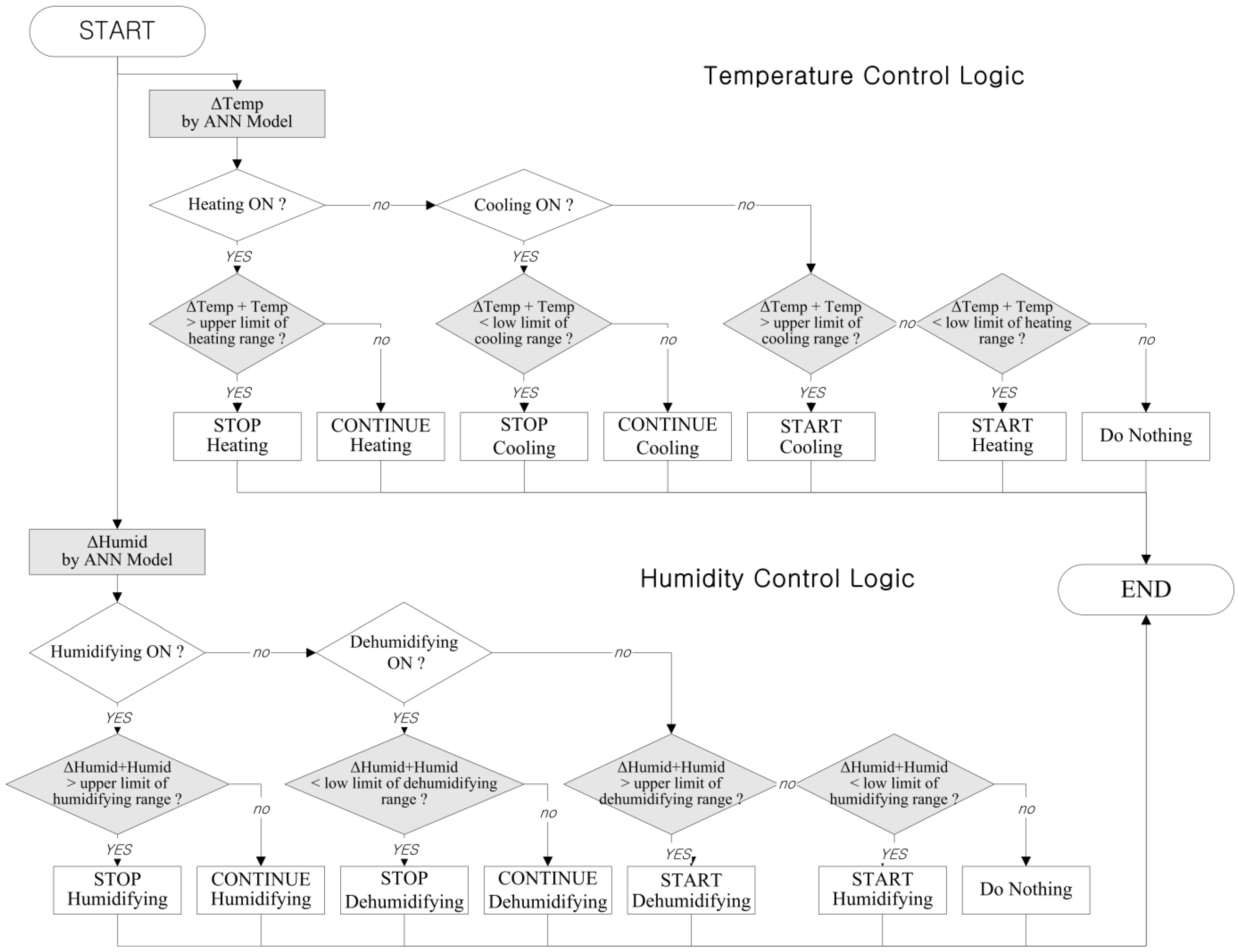
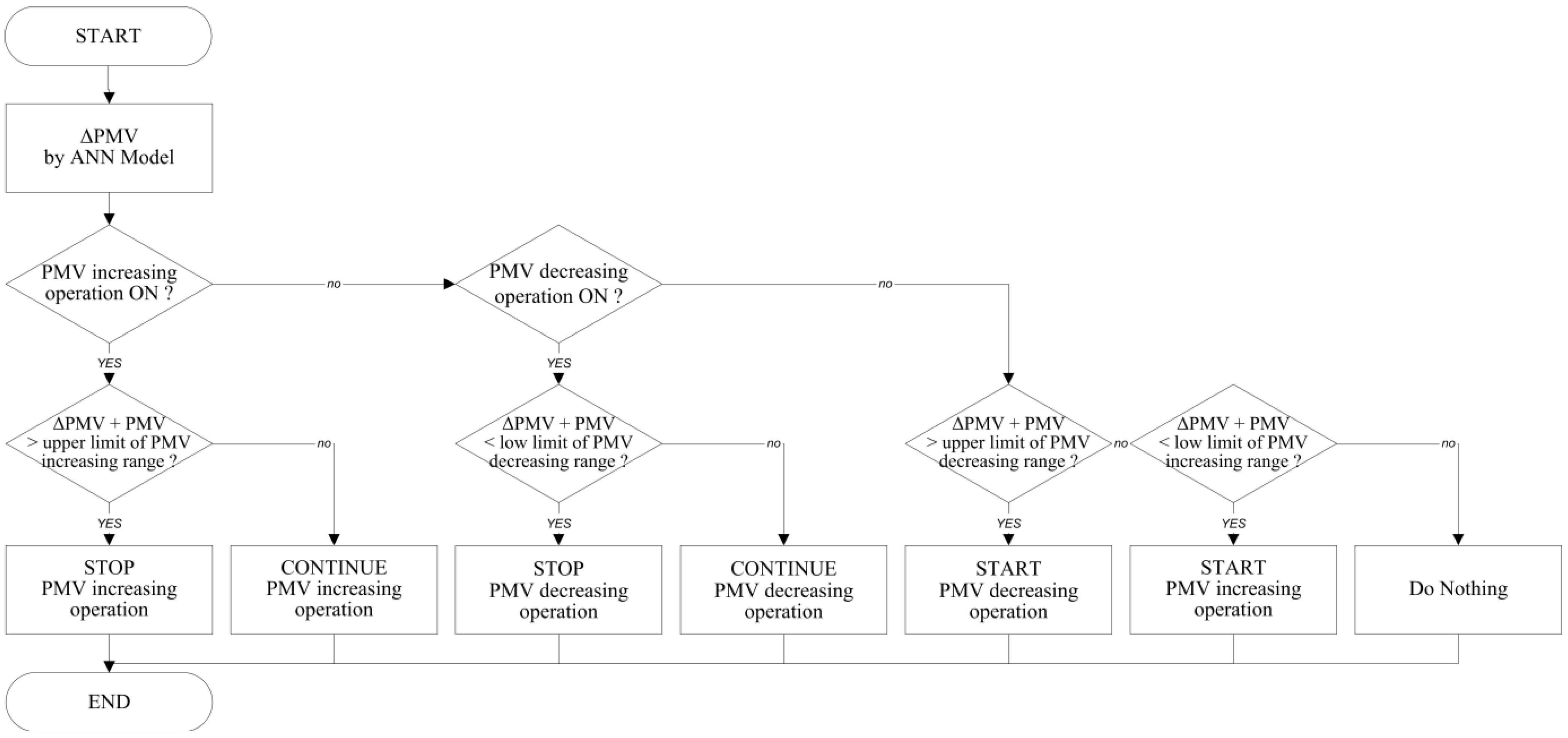
Of the four logics, two employed ANN models for predictive and adaptive control. The ANN-based control logics for temperature, humidity, and predicted mean vote (PMV) are shown in Figure 1 and Figure 2. Three ANN models were developed to calculate ∆Temperature, ∆Humidity, and ∆PMV based on a series of inputs that represent the variations of temperature and humidity for indoor and outdoor environments.
Figure 1. ANN-based temperature and humidity control logic.
Energies 06 03548 g001
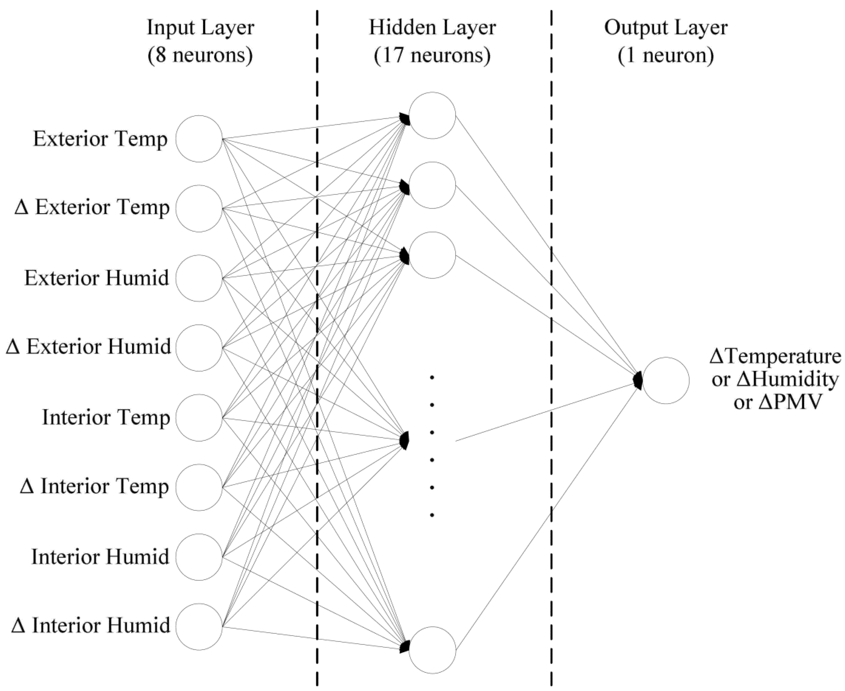
The structure of the input used for the ANN models is shown in Figure 3. Three models have identical structures except the output neuron. Each model calculates ∆Temperature, ∆Humidity, and ∆PMV. ∆Temperature, ∆humidity, and ∆PMV refer to the amount of the increase or decrease of the variables from the time at which the operating conditions of the heating or cooling system are changed. For example, in winter, when an operating heating device is turned off, the indoor temperature continues to rise a certain degree for a period of time due to the time-lag of the device and the thermal inertia of the room. This temperature change is referred to as ∆Temperature. Since the ANN model predicts and uses ∆Temperature, ∆Humidity and ∆PMV every minute for predetermining the operations of the devices, the logic can effectively stabilize the temperature, humidity and PMV within the targeted comfort range. The thermal control logics were also tested for their ability to adapt to changes in user requirements, such as the application of a setback or a change in the setpoint [15]. The results showed that the ANN-based logics improved the thermal conditions because they reduced the frequency of overshoots and undershoots outside of the thermal comfort range.
Figure 2. ANN-based PMV control logic [3,12,15,16].
Energies 06 03548 g002
Figure 3. Structure of ANN models [3,12,15,16].
Energies 06 03548 g003
Most of the previous studies employed a fixed training data method that does not add new training data sets during the operations of the systems, despite the advantages of the sliding window training method for the ANN model, which adds a new data set to the training data sets by replacing the oldest set for the regulation of thermal conditions and energy efficiency [18,19]. Thus, those ANN-based models could not update the weights between neurons for new circumstances such as changes in user requirements, various building background conditions, and climatic disturbances. For the training, training goals were set at 0.1 °C for temperature, 0.1% for humidity, and 0.1 for PMV with 0.75 learning rate, 0.9 moment and 1000 times maximal epoch. In addition, the Levenberg-Marquardt algorithm was employed as a training algorithm.
Using adaptive ANN models, the proposed logics demonstrated their advantages in controlling home climate control devices to deliver user-specified conditions. However, the proposed logics in those studies were tested with limited variables, such as a base case, changes in user requirements, and climatic disturbances.
Therefore, the adaptability performance of the proposed logics in those studies must be further verified with more variables that cover the dynamic environmental conditions experienced by residential buildings. This study aims to examine the performance and adaptability of the four proposed control methods to work stably in residential buildings for various building conditions. The computational application consists of two phases that were employed in this study. First, the proposed logics were applied in a building of various envelope insulations and window-to-wall ratios on envelopes. Next, the thermal conditions of two ANN-based logics were comparatively analyzed against their non-ANN-based counterparts.

2. Validation of Simulation Results for Thermal Control Logics

In this study, ANN-based control logics and non-ANN based conventional control logics were employed to examine thermal control performance for residential buildings under a variety of building envelope conditions. The primary analysis results in this study are based on computer simulations that incorporated the International Building Physics Toolbox (IBPT) [20] and MATLAB [21]. The IBPT employs the heat and moisture balance equations given below for calculating the thermal conditions in buildings.
The heat balance equation is as follows:
T i n + 1 Δ t =   1 C n     { [ ( T i 1 T i ) R i 1 + R i + ( T i + 1 T i ) R i + 1 + R i ] h e v a p [ ( p i 1 p i ) R p , i 1 R p , i + ( p i 1 p i ) R p , i + 1 R p , i ] } + { m a c p a ( T i 1 T i ) n ,   m a > 0 m a c p a ( T 1 T i + 1 ) n , m a < 0 }
Moisture balance equation:
w i n + 1 w i n Δ t =   1 d { [ ( p i 1 p i ) R p , i 1 + R p , i + ( p i + 1 p i ) R p , i + 1 + R p , i ] [ ( p s u c , i 1 p i s u c , i ) R s u c , i 1 R s u c , i + ( p s u c , i + 1 p s u c , i ) R s u c , i + 1 R s u c , i ] } + { 6.21.10 6 m a ( p i 1 p i ) n , m a > 0 6.21.10 6 m a ( p i p i + 1 ) n , m a < 0 }
where:
T: air temperature (°C)t: time
C: thermal capacity (J/kg·K)R: thermal resistance (m2·K/W)
hevap: latent heat of evaporation (J/kg)p: density of the material (kg/m3)
ma: density of moisture flow rate of dry air (kg/m2·s)d: thickness (m)
cpa: specific heat capacity of dry air (J/kg·K)suc: suction
w: moisture content mass by volume (kg/m3)i: the objective node
i − 1: the preceding nodei + 1: the following node
n: previous time stepn + 1: the corresponding time step
The simulation results were validated against field measurement results in order to perform further computer simulations with improved reliability for residential buildings. The measurement data were collected from a thermal chamber that was controlled under various thermal control settings. In order to perform the validation process, the measurement conditions of the chamber were equally modeled using computer simulation software.
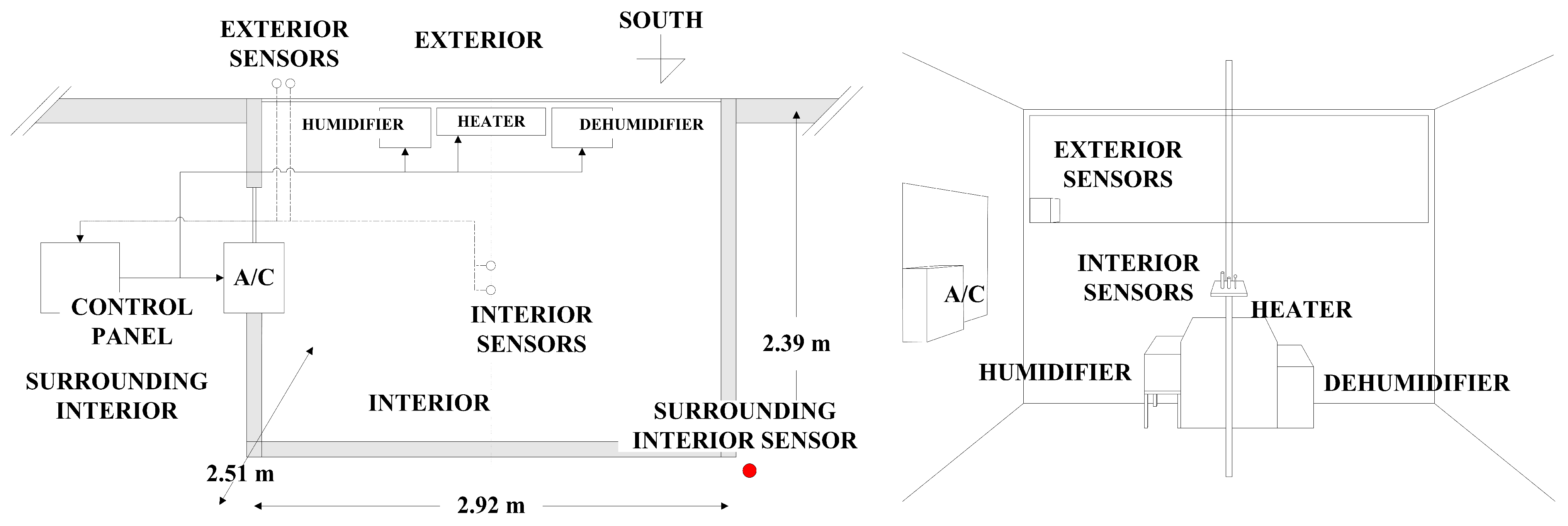
A thermal chamber was built in a high-bay space for the field experiment. Figure 4 illustrates the detailed configuration and conditions of the chamber. The dimensions of the chamber were 2.92 m (width) × 2.39 m (depth) × 2.51 m (height). The south-facing envelope of the chamber, which contained a single window, was adjacent to the outdoor environment, and the remaining chamber envelopes were exposed to the indoor environment surrounded by the high-bay space.
A window with dimensions of 1 m by 1 m was installed on the east-facing envelope. The south-facing window was covered with several layers of rigid insulation panels in order to block any solar radiation and to prevent its impact on the indoor thermal conditions. The R-values of the floor, roof, and east, west, and north-facing envelopes were 3.7, 3.6, 3.6, 0.18 and 3.6 °K m2/W, respectively. The R-value of the south and east-facing windows was 0.4 °K m2/W.
Figure 4. Layout of thermal chamber (Left: plan, Right: perspective) [15,17].
Energies 06 03548 g004
A thermal control system was installed for data monitoring. The system included sensors, a data acquisition system, control panel, and climate control devices such as a radiant heater, air conditioner, humidifier, and dehumidifier. The data monitoring was conducted on 23 December 2007. During this period, the dry-bulb temperature, relative humidity and the operating conditions of the heating and humidifying systems were monitored at every minute. A conventional logic based on non-ANN-based temperature and humidity control was used for the thermal control of the chamber. Data were automatically recorded under various weather conditions, and transferred to a personal computer for further analysis.
In order to compare the measurement data with the simulated results, the measurement conditions set up for the chamber were equally modeled using IBPT, which is a toolbox for calculating building thermal dynamics, in conjunction with MATLAB and Simulink. For the simulation, the infiltration rate of the chamber was assumed to be 1.0 air change per hour (ACH) based on the generally used guidelines for building construction [22].
The operating range of the heating system set up in the simulation was from 20 °C to 23 °C for thermal comfort according to general guidelines [23], under which the comfort ranges for winter and summer are from 20 °C to 23.5 °C and 23 °C to 26 °C, respectively. Based on the zero-band method, the operating range of the heating system (20 °C to 23 °C) was determined not to be overlapped with that of the cooling system (23 °C to 26 °C). For the assumed simulation conditions, the conventional logic, which is non-ANN-based temperature and humidity control, was applied and used to generate the simulation results.
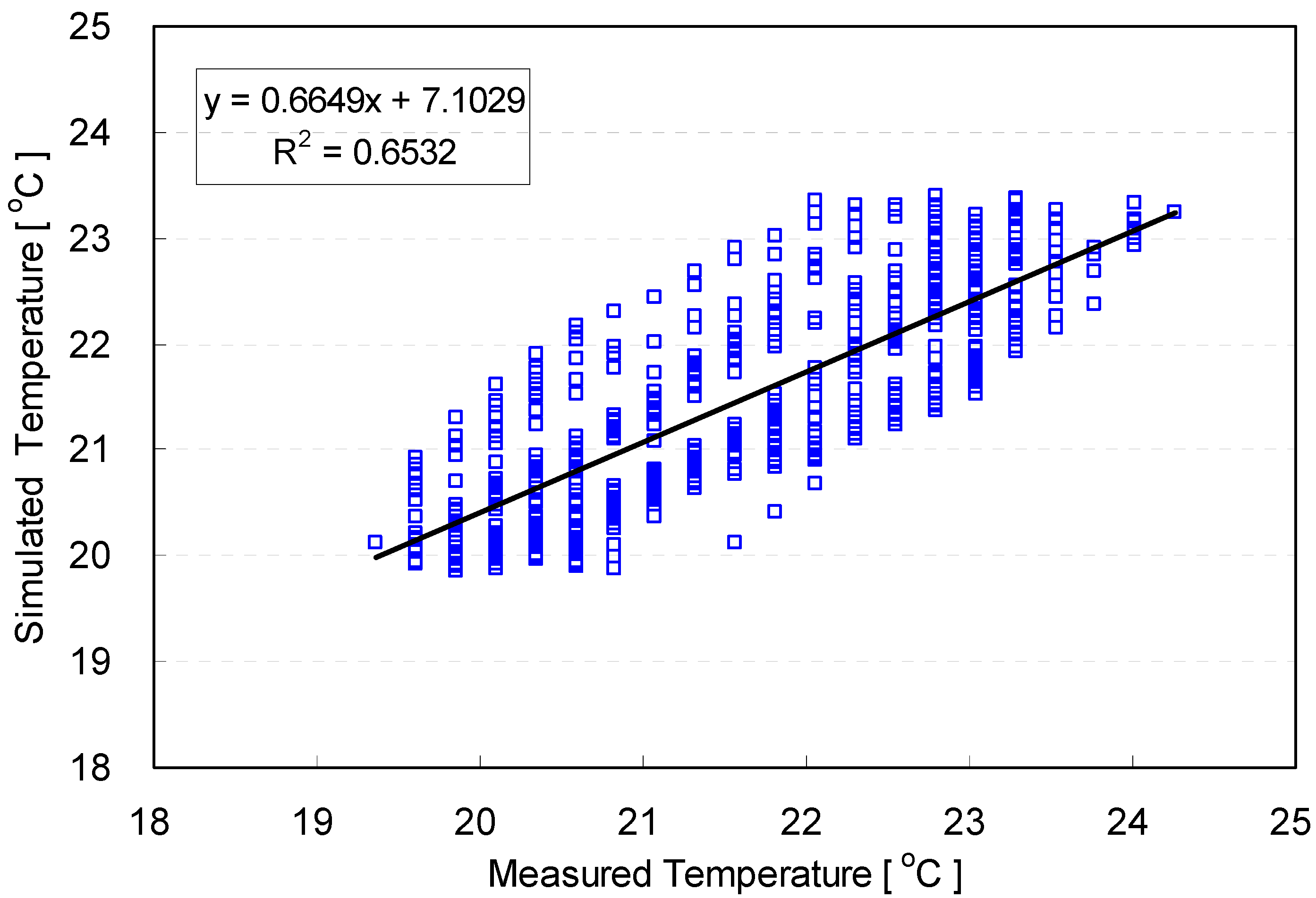
In order to examine the relationship between measured and simulated air temperature, linear regression method was used in this study. Using the regression method, a prediction model that explains the relationship between them was determined. Measured and simulated temperature were used as independent and dependent variables, respectively. The relationship between measured and simulated air temperature in the chamber space is shown in Figure 5 and Table 1.
Figure 5. Comparison of air temperature between experiment and numerical simulation.
Energies 06 03548 g005
Table 1. ANOVA test result for linear regression model.
FactorsUnstandardized CoefficientstSig.
BStd. Error
Constant0.71000.4515.880.00
Measured temperature0.6650.0232.210.00
ANOVAR2 = 0.6532, F(1, 551) = 346.59, Sig. = 0.00
Overall, no significant difference was noted between the measured and simulated results. The regression result indicates that simulated air temperature has a fairly strong linear relationship with measured air temperature in the chamber. The coefficient of determination for the regression model was 0.6532, which means that the error variance for simulated temperature was reduced by 65.32%, when measured temperature was used to predict the simulated temperature. The ANOVA test result shown in Table 1 also implies that the model was meaningful at a very low significant level. In summary, the similarities in the air temperature profile measured from the field experiments and simulations provided effective grounds for further computer simulations to analyze the influence of control logics on the indoor thermal environment.

3. Thermal Performance Tests of Developed Control Logics

3.1. Simulation Conditions

For the computer simulation that was used a primary analysis tool in this study, a thermal performance test was performed for a typical two-story single-family house using the four developed control logics. The house was assumed to be located in Detroit, MI, in the USA (latitude: 42.19° N, longitude: 83.2° W). The detailed configuration of the house is shown in Figure 6.
Figure 6. Views of tested building (Left: from South-East, Right: from North-West).
Energies 06 03548 g006
The long axis of the building was in the south and north directions. The net area for each floor was 92.2 m2. One wooden door and four windows were installed on both the south-facing and north-facing façades. The east-facing façade contained three windows and one door. Four windows were installed on the west-facing façade. No windows existed on the rooftop.
The thermal properties and detailed conditions that were assumed for the computer simulations are summarized in Table 2. The assumed R-values indicating the insulation capability were 3.7 and 6.69 °K m2/W for the floor and roof, respectively. The R-values for the wall and door were 3.35 and 0.2 °K m2/W, respectively. The window-to-wall ratios on the facades ranged from 0.08 to 0.24. The R-value of the window was 0.61 °K m2/W. The infiltration rate was assumed to be 0.3 ACH, and the indoor air temperature was 23 °C to meet comfortable thermal conditions.
The properties shown in Table 2 were used as boundary conditions for a base case of the thermal performance test in this study. A variety of building thermal properties were set up for the simulation conditions in order to examine the influence of thermal properties and control logics on the indoor thermal environment. Table 3 shows the simulation conditions used for the performance tests. The four thermal control logics in Table 3 were comparatively tested for various thermal property conditions in winter and summer. Under the conditions in Table 3, the simulations were performed for six selected days in summer and winter to represent the peak heating and cooling days in each season.
The test variables for the simulation were related to the building configuration shown in Table 3. The simulations were parametrically conducted according to the base and other alternative cases as shown in Table 2 and Table 3. First, when the R-value of one component was changed, the R-values of the other components were held constant relative to the base case. Next, when the window-to-wall ratio was changed, the ratio was applied equally to every facade. That is, as the window-to-wall ratio increased, the window area increased for all directions.
The temperature and humidity control logics operated the temperature and humidity systems separately in the winter and summer. However, the systems worked together under the PMV control logics. For example, the heating and humidifying systems worked simultaneously to increase the PMV. Based on the simulation results, analysis was conducted for the last five days after trimming away the first day in order to remove any unstable test results associated with the start of the simulation.
Table 2. Thermal properties for tested building.
Location/Weather DataDetroit, MI, USA/TMY2
Building size184.4 m2 (92.2 m2 for each floor)
EnvelopeRatio of window to wall0.15 on average (- East: 0.14, - West: 0.13, - South: 0.24, - North: 0.08)
Insulation (°K m2/W)- Wall: R-value 3.35; - Roof: R-value 6.69; - Floor: R -value 3.7;
- Windows: R-value 0.61; - Door: R-value 0.2
Infiltration Rate0.3 ACH
OrientationSouth
Internal Heat GainsHourly-weighted heat and moisture gains for a family of four people [24,25]
Thermal Control SystemsConvective heating: 9,000 W att heat supply
Convective cooling: 10,000 W att heat removal
Humidifying: 1.41 K g/h moisture supply
Dehumidifying: 2.36 K g/h moisture removal
AssumptionsInitial air temperature: 23 °C
Initial humidity: 45%
Mean Radiant Temperature (MRT): same as air
temperature [3,12,13,14,15,16]
Air velocity: 0.0 m/s
Activity level: 1.0 M ET
Clothing level: 1.0 CLO (winter) and 0.5 C LO (summer)
Table 3. Simulation conditions for performance test.
PropertiesContent
R-value (°K m2/W)Wall2.64, 3.35, 5.28, 7.04, (base case: 3.35)
Roof1.76, 5.28, 6.69, 8.81, 12.33, (base case: 6.69)
Window0.18, 0.53, 0.61, 0.88, 1.23, 1.59, (base case: 0.61)
Window to wall ratio0.1, 0.15, 0.2, 0.3, 0.4, 0.5 (base case: 0.15)
Infiltration rate0.3 ACH
DaySummer: January 27–Feberary 1 on a daily basis
Winter: July 3–July 8 on a daily basis
Targeted thermal comfort rangeIndoor air temperature in winter: 20 °C–23 °C
Indoor air temperature in summer: 23 °C–26 °C
Humidity in winter: 30%–45%
Humidity in summer: 45%–60%
PMV in winter: −0.5–0.0
PMV in summer: 0.0–0.5
Thermal control logics(1) ANN-based Temperature and Humidity Control
(2) Non-ANN-based Temperature and Humidity Control
(3) ANN-based PMV Control
(4) Non-ANN-based PMV Control

3.2. Prediction Performance of ANN Model
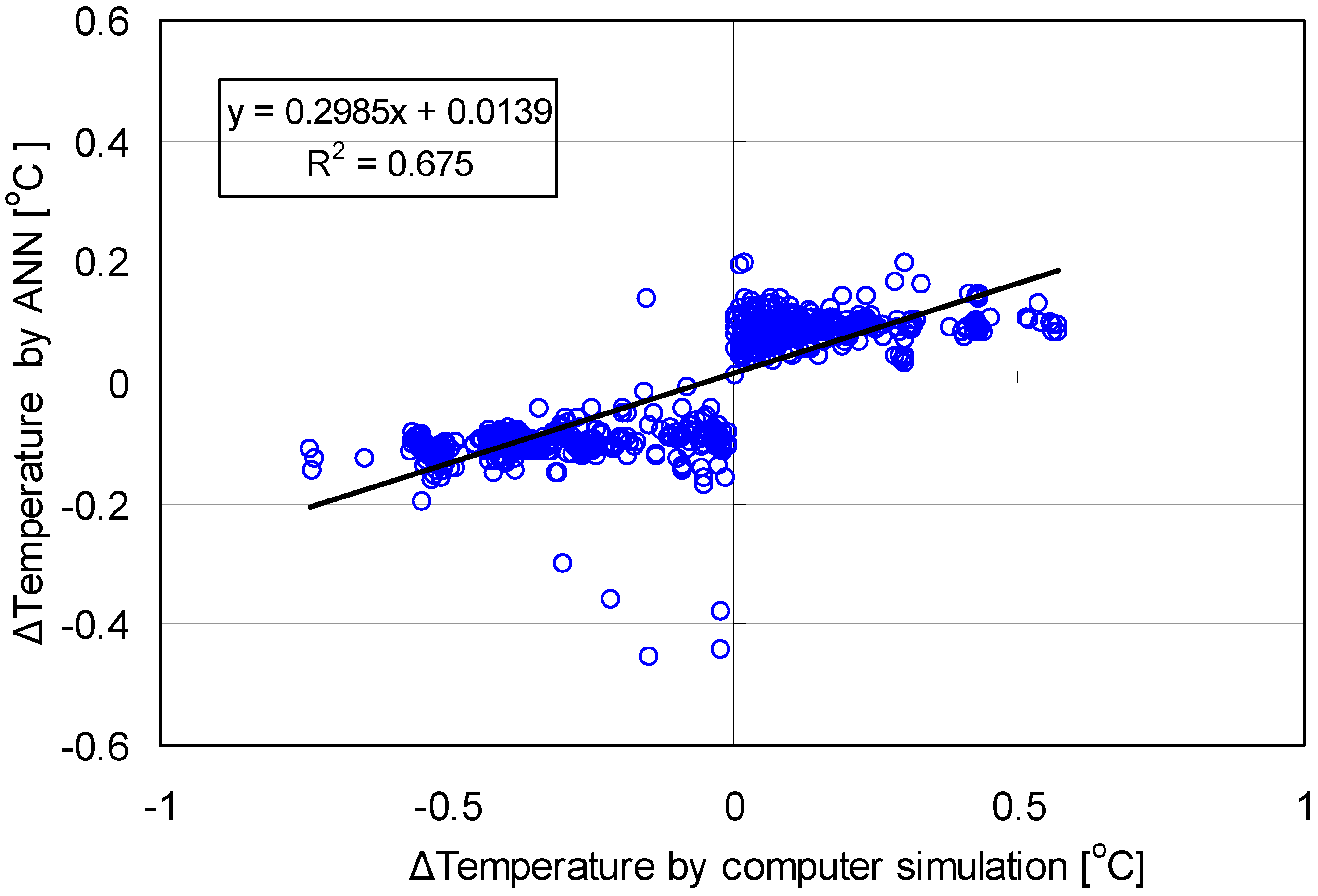
The accuracy of the ANN model prediction was examined based on the ΔTemperature predicted by the ANN model and computer simulations that incorporated the International Building Physics Toolbox (IBPT) and MATLAB. The base case condition shown in Table 2 was used for both computational processes. The linear relationship between the ΔTemperature predicted by the ANN-based model and the ΔTemperature calculated by the computer simulation is shown in Figure 7.
Figure 7. Relationship of ΔTemperature between computer simulation and ANN model.
Energies 06 03548 g007
The values obtained by the two methods show a strong relationship between them. The linear regression model was acceptable under a very low significance level, as shown in the ANOVA test result in Table 4. The coefficient of determination (r2) of the model was 0.6586. This implies that the error variance in ΔTemperature from the ANN-based model was reduced by 65.86% when the ΔTemperature from the computer simulations was used to predict ΔTemperature from the ANN-based model. In summary, the linear regression model showed that the developed ANN models can be effectively applied to predict the indoor air temperature condition.
Table 4. Linear relationship of ΔTemperature between computer simulation and ANN model.
FactorsUnstandardized CoefficientstSig.
BStd. Error
Constant0.0130.0025.8920.00
Computer Simulated0.2980.00838.6450.00
ANOVAR2 = 0.6586, F(1, 299) = 1,493.44, Sig. = 0.00

3.3. Thermal Performance of the Developed ANN Logic
Simulations using the developed thermal control logics were conducted on a daily basis for the designated periods under various environmental conditions during different seasons. All of the simulation results were analyzed according to two categories: (1) the percentage of periods within the targeted range for thermal comfort; and (2) the magnitudes of the overshoots and undershoots outside of the targeted range.
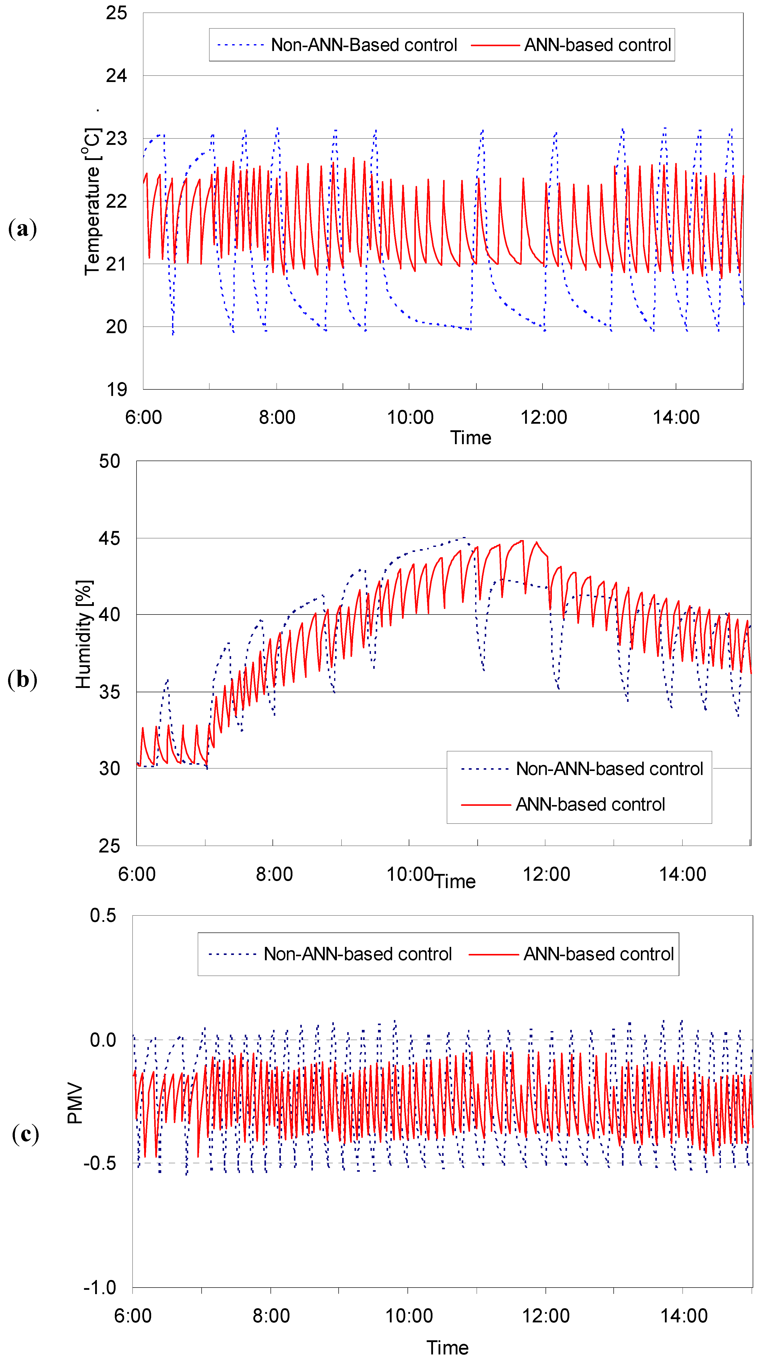
Figure 8 presents the profiles of the air temperature, humidity and PMV that were produced using the non-ANN-based and ANN-based logics for a selected day in winter. The non-ANN-based temperature and humidity control logic resulted in unstable air temperature levels that exceeded the comfort range. However, the ANN-based temperature and humidity control logic was able to effectively stabilize the temperature within the comfort range.
Both of the logic schemes properly conditioned for humidity because the humidity control systems did not experience a significant time lag. Instead, the fluctuations in the humidity depended on the movement of the air temperature, when the air temperature increased and the humidity dropped. Thus, small-scale humidity fluctuations existed in one large cycle of humidity movement. The ANN-based PMV control logic also fit better within the comfort range than the non-ANN-based logic, due to the reduction in overshoots and undershoots.
Figure 8. Comparative profiles of thermal factors of non-ANN and ANN-based logics in winter (Base case 6:00–15:00 on January 30, 2007). (a) Temperature control logic; (b) Humidity control logic; (c) PMV control logic.
Energies 06 03548 g008

3.3.1. Percentage of Period within Targeted Range for Thermal Condition

In order to analyze the thermal comfort performance of each control logic scheme, comparisons were made between the percentage of time during which each control logic was able to keep the indoor temperature within the targeted comfortable ranges shown in Table 3. The ANN-based temperature and humidity control logics kept the indoor air more comfortable when the R-values, meaning the heat thermal resistance of the building envelopes, varied. The percentages of the period within the comfortable range according to the R-values of the walls, roof and window are shown in Table 5, Table 6 and Table 7. Overall, the ANN-based control logics kept the air more comfortable than the non-ANN based control logics.
The changes of the R-values influenced the periods during which thermal comfort was maintained. In the winter, the improvement ranged from 3.3% to 4.6% according to the changes in the wall insulation. As the R-value of the roof increased, the period increased from 2.9% to 7.1%.
The change in the window caused a maximum of 5.0% improvement in the period. In the summer, the improvement in the period was reduced compared to that in the winter. The maximum influences of the wall, roof and window on the period were 4.1%, 3.9% and 4.1%, respectively. The comfort periods during which the humidity was maintained within the targeted range were close to 100% when ANN-based and non-ANN based logics were employed. As shown in Table 5, Table 6 and Table 7, no significant differences were found between the results.
Table 5. Percentage of period within comfortable range according to R-value of wall (unit: %).
Thermal propertySeasonControl logicR-vale of wall (°K m/W)
2.643.355.287.04
TemperatureWinternon-ANN90.795.895.495.3
ANN94.0100.0100.099.9
Summernon-ANN96.396.195.996.0
ANN100.0100.0100.0100.0
HumidityWinternon-ANN99.999.9100.0100.0
ANN100.0100.0100.0100.0
Summernon-ANN99.299.299.499.3
ANN98.899.999.1100.0
Table 6. Percentage of period within comfortable range according to R-value of roof (unit: %).
Thermal propertySeasonControl logicR-value of roof (°K m/W)
1.765.286.698.8112.33
TemperatureWinternon-ANN85.692.995.895.995.9
ANN88.5100.0100.0100.0100.0
Summernon-ANN96.596.196.196.196.1
ANN100.0100.0100.0100.0100.0
HumidityWinternon-ANN99.899.999.9100.0100.0
ANN100.0100.0100.0100.0100.0
Summernon-ANN99.399.299.299.399.4
ANN99.799.099.999.799.5
Table 7. Percentage of period within comfortable range according to R-value of window (unit: %).
Thermal propertySeasonControl logicR-value of window (°K m/W)
0.180.530.610.881.231.59
TemperatureWinter non-ANN66.1691.7795.8095.5395.2095.01
ANN67.3495.40100.0099.99100.00100.00
Summernon-ANN96.3196.0896.0896.0196.0095.95
ANN98.61100.00100.0099.9799.97100.00
HumidityWinternon-ANN99.8999.9799.9499.9499.9499.94
ANN100.0099.97100.0099.75100.0099.42
Summernon-ANN99.2499.2199.1599.1799.1799.22
ANN99.9299.7299.9099.6899.5499.96
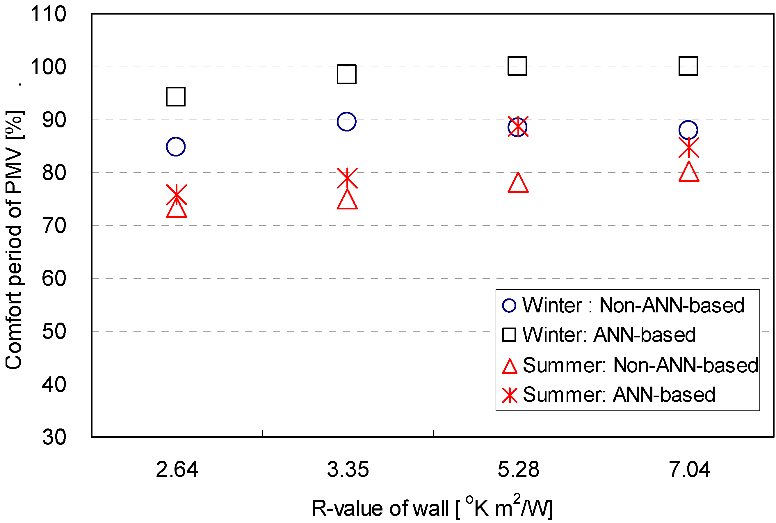
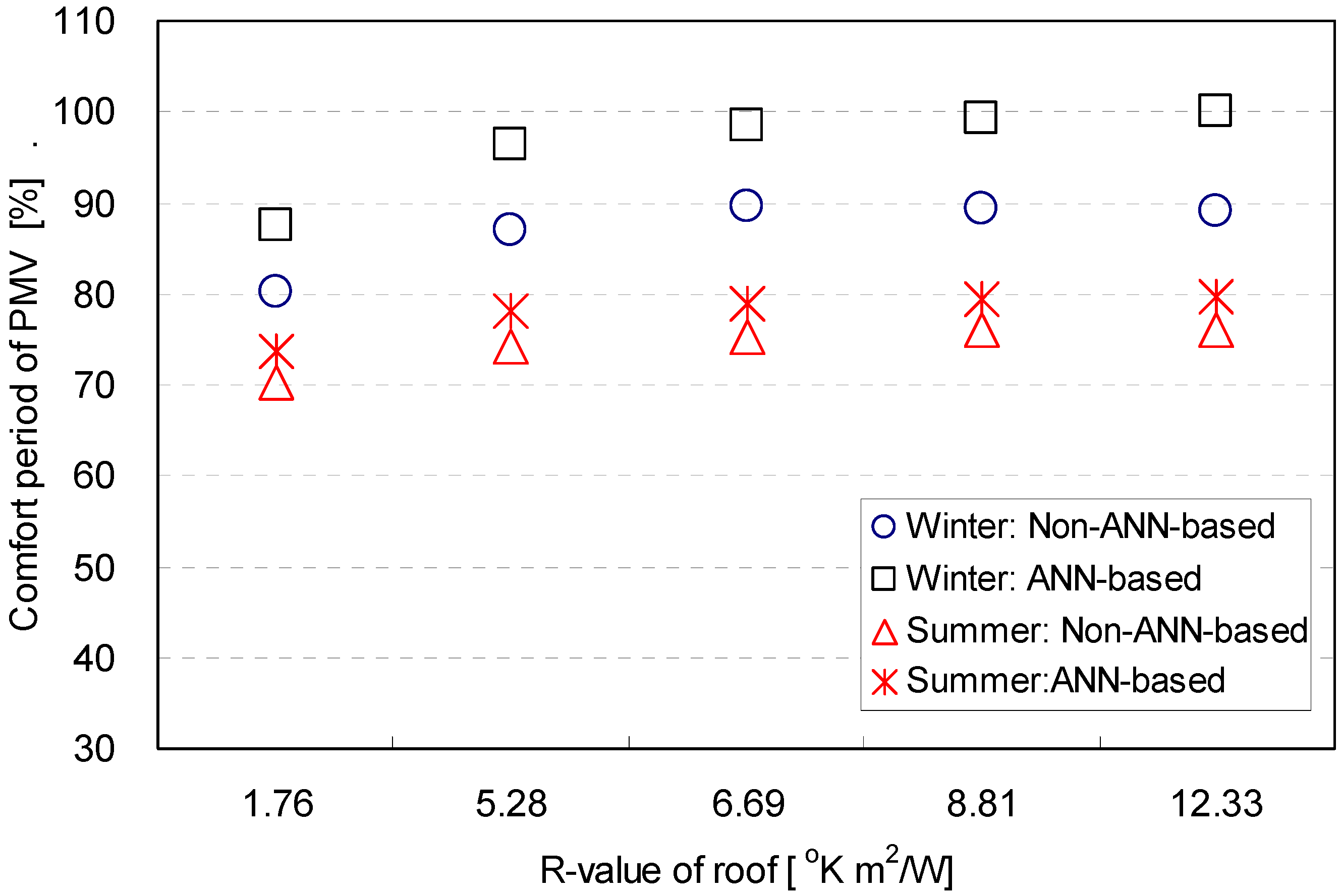
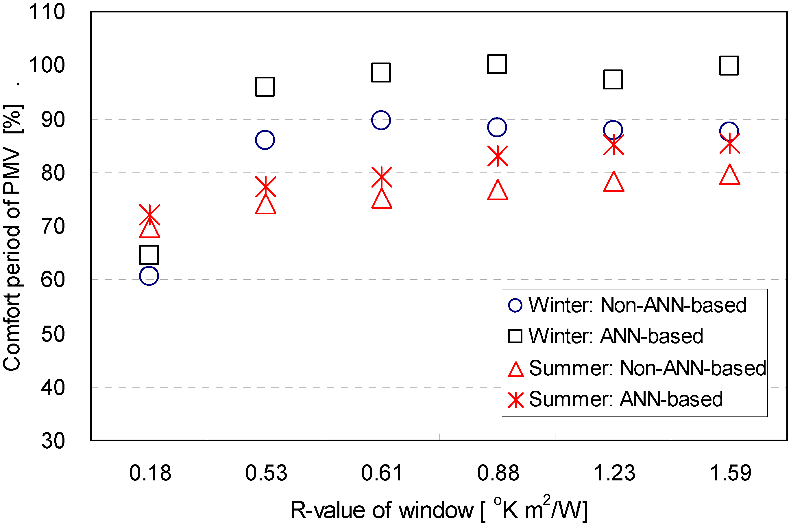
The ANN-based PMV control logic provided better PMV values than the non-ANN-based PMV control logic in winter and summer. The percentages of the periods during which the PMV was within the targeted range are shown in Figure 9, Figure 10 and Figure 11. Overall, the range of the improved period using the ANN-based logics in winter was longer than in summer. When the R-values of the wall and roof varied, the maximum improved periods of thermal comfort were 11.9% and 10.9%, respectively. The change in the window effectively improved the period. During the summer period, the change in the wall insulation improved the period by 10.3%. The comfortable period varied from 3.3% to 3.9% when the R-value of the roof was varied. The change of the window caused a 6.7% improvement in the period.
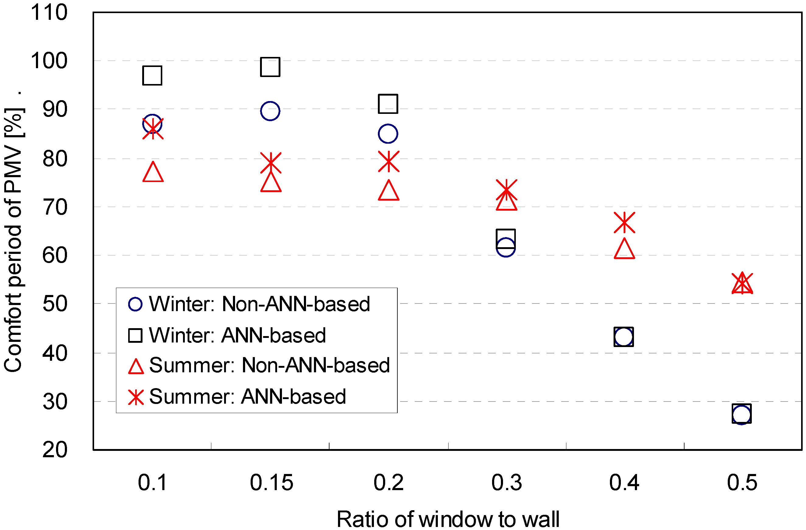
The percentage of the period during which thermal comfort was maintained decreased as the window-to-wall ratio increased in both summer and winter. Table 8 shows the percentage of the period within the comfortable range according to the ratio of window to wall areas. The period decreased noticeably when the ratio was 0.15 and 0.3 in winter and summer, respectively. This decrease occurred because the heating and cooling devices equipped in the simulation were unable to control the air temperature comfortably, when excessive heat loss and gain existed due to the increased area of window space on the wall.
Figure 9. PMV comfort periods based on R-values of walls.
Energies 06 03548 g009
Figure 10. PMV comfort periods based on R-values of roof.
Energies 06 03548 g010
Figure 11. PMV comfort periods based on R-values of windows.
Energies 06 03548 g011
Table 8. Percentage of period within comfortable range according to ratio of window to wall (unit: %)
Thermal propertySeasonControl logicRatio of window to wall
0.10.150.20.30.40.5
TemperatureWinternon-ANN94.793.789.366.549.731.7
ANN98.8100.091.867.249.732.5
Summernon-ANN95.896.196.794.986.077.3
ANN100.0100.0100.098.185.777.3
HumidityWinternon-ANN99.999.9100.099.892.759.8
ANN100.0100.0100.0100.094.162.2
Summernon-ANN99.299.299.298.697.998.1
ANN99.499.998.499.099.999.6
The ANN-based temperature and humidity control logics provided longer periods of thermal comfort in terms of the air temperature than the conventional non-ANN-based control logics. The maximum improvement with the ANN-based logic was 4.2% in both seasons. The comfortable periods during which thermal comfort was maintained in terms of the humidity were similar when the conventional non-ANN-based control logic and the ANN-based control logics were used for an indoor space. This result implies that the ANN-based logic did not significantly influence the humidity.
For both ANN-based and non-ANN-based control logics, the percentage of the comfort period for a high ratio of window to wall in the winter dropped because the indoor humidity was maintained above the targeted comfort range without the operation of a humidifying device. The high level of relative humidity was a result of the indoor air temperature falling in the case of a high ratio of window to wall such as 0.4 or 0.5 due to excessive heat loss through the windows.
The ANN-based control logics improved the PMV conditions in winter and summer. The percentage of the comfortable period is shown in Figure 12. The increase in the period ranged from 2.0% to 8.6% in the summer. The maximum improved period with the ANN-based logic was 10.1% in the winter. In summary, the results imply that the ANN-based control logics effectively controlled the air temperature and PMV within the comfortable range under diverse building thermal properties and geometrical conditions.
Figure 12. PMV comfort periods based on ratio of window to wall.
Energies 06 03548 g012

3.3.2. Magnitude of Overshoots and Undershoots out of Targeted Comfort Range

The magnitudes of the overshoot and undershoots out of the targeted comfort temperature were determined in this study in order to diagnose the thermal control performance of the control logic schemes. The magnitude for each condition was calculated using the degree and duration time of the undershooting and overshooting. The magnitude for the entire simulation period using the control logics was the summation of the multiplication of the degree and the duration time as indicated in the formula below:
S = ∑(Δ × t)
where: S: magnitude of overshoot or undershoot out of targeted comfort range; Δ: degree of overshoot or undershoot out of targeted comfort range (°C, or %, or PMV); t: duration time of overshoot or undershoot out of targeted comfort range (min).
In this study, the control logics contained three environmental factors: the temperature, humidity, and PMV. When a control logic focusing on one of the factors was applied to the control space, the magnitude was the duration time multiplied by one of the three factors. For instance, the magnitude was the duration time multiplied by the degrees of the overshoots or undershoots out of the targeted temperature range for thermal comfort when the temperature control was employed to control the thermal environment.
When the insulation of the envelope was changed, the ANN-based control logics also effectively reduced the magnitudes of undershoots and overshoots in terms of the temperature, humidity and PMV. The variations of the magnitudes for various R-values of the envelope are shown in Table 9 and Table 10. Overall, the ANN-based control logics kept the magnitudes very close to the targeted comfortable ranges, but the non-ANN-based logics failed to keep them near the targeted range for the given conditions.
In winter, the magnitude of the overshoot when using the ANN-based logics in terms of temperature did not exceed 0.49, and no undershoot existed. For a majority of cases, the magnitude was equal to zero, which means that the control system was very effective at meeting the targeted temperature. The non-ANN-based control logic generated a greater magnitude than the ANN-based logic. The maximum magnitudes of the overshoot and undershoot were 4.8 and −6.5, respectively.
In summer, the ANN-based logic also achieved excellent control performance, keeping the magnitude range narrower than 0.51. The non-ANN-based logic generated greater ranges of magnitude. Its maximum values for the overshoots and undershoots were 5.75 and −7.66, respectively. The result implies that the indoor temperature was more effectively maintained by the ANN-based control logics than by the non-ANN based logics.
As shown in Table 9, the magnitudes of the overshoot and undershoot in terms of the indoor humidity were also reduced by the ANN-based control logics. The magnitudes in winter were less than 0.58, and this implies that very excellent control performance was achieved in terms of humidity when a variety of R-values were applied to the building envelopes. The non-ANN-based control showed slightly ineffective control that generated a maximum magnitude of 0.91 for the heating condition.
The control performance in summer was less effective than in winter. The magnitudes of the overshoots and undershoots were higher in summer than in winter. The maximum magnitudes of the overshoot and undershoot using ANN-based logics were 4.1 and −2.83, respectively. The non-ANN-based control logics showed worse control performance. The maximum magnitudes for the overshoot and undershoot were 36.56 and −1.14, respectively. This result implies that the control performance with the ANN-based logic was more effective for reducing the overshoots of the dehumidifying device in summer.
Table 9. Magnitude of overshoots and undershoots of air temperature and humidity based on envelope insulation.
FactorEnvelopeR-value (K m2/W)WinterSummer
Non-ANN basedANN-basedNon-ANN basedANN-based
Over shootUnder shootOver shootUnder shootOver shootUnder shootOver shootUnder shoot
TemperatureWall2.643.5−5.17004.75−6.2800
3.353.95−6.1005.4−7.100
5.284.8−6.10.0905.46−7.3600
7.044.42−5.790.605.75−6.2900
Roof1.763.42−5.10.4904.72−7.6600
5.283.64−5.17005.1−7.2100
6.694−6.5005.41−7.0700
8.813.93−5.42004.78−7.5800
12.333.66−5.83004.81−6.7900
Window0.181.84−3.51005.31−7.0400
0.533.42−4.51004.69−6.9500
0.613.69−4.89005.35−6.5900
0.883.66−4.60.0304.73−7.340−0.14
1.233.44−3.98004.69−6.880−0.51
1.593.53−3.2005.33−6.8800
HumidityWall2.640.07−0.110.58034.48−1.050−2.83
3.350.18−0.110031.67−1.10.22−0.2
5.28----18.33−0.910−2.51
7.04----12.29−0.531.530
Roof1.760.91−0.010033.49−0.850.04−0.18
5.280.04−0.030036.56−0.730.2−0.59
6.690.19−0.110031.67−1.10.22−0.2
8.810.01−0.0010021.92−0.70−0.39
12.330.01−0.060016.12−0.790−0.56
Window0.18----27.82−0.854.10
0.530.01−0.010024.15−0.610.26−0.15
0.610.1−0.110031.67−1.10.22−0.21
0.880.04−0.030032.27−0.690−0.2
1.230.03−0.010019.46−1.140−0.28
1.590.09−0.010.04030.85−0.8400.02
As shown in Table 10, the magnitudes of the overshoot and overshoot in terms of the PMV were also effectively diminished by the ANN-based control logics. In winter, most of the magnitudes, with the exception of two cases, were very close to zero, which means that the thermal control performance was very effective and met the targeted conditions. The non-ANN-based control achieved weak control performance compared to the ANN-based control. Wider ranges of magnitude variations were generated for the majority of cases. The magnitudes of the overshoots and undershoots varied from 2.39 to 6.84 and from −4.92 to −9.09, respectively.
Table 10. Magnitude of overshoots and undershoots of PMV based on envelope insulation.
FactorEnvelopeR-value (°K m/W)WinterSummer
Non-ANN basedANN-basedNon-ANN basedANN-based
Over shootUnder shootOver shootUnder shootOver shootUnder shootOver shootUnder shoot
PMVWall2.645.1−8.090.04015.67−21.314.35−2.15
3.355.7−8.340−0.6514.1−23.511.65−8.81
5.286.84−7.690012.68−25.332.68−1.04
7.046.82−7.760−0.0512.43−26.811.84−4.04
Roof1.764.46−6.140−0.0215.39−18.620.05−7.78
5.285.52−9.090−0.115.1−22.211.94−11.02
6.695.71−8.430−0.6514.1−23.511.65−8.81
8.815.81−8.090−0.5614.41−23.350.14−11.14
12.336.14−7.990014.01−22.540−13.27
Window0.182.39−4.920015.17−19.619.3−3.53
0.535.19−7.40014.32−22.294.73−5.76
0.615.43−6.640−0.6213.87−22.151.65−7.44
0.886.26−5.680014.01−22.870.9−3.17
1.236.67−5.850−0.0314.42−23.680.37−4.17
1.596.5−5.30013.61−24.090.02−4.5
Overall, the ranges of magnitude in summer were wider than in winter. For the ANN-based logic, the ranges for the undershoot were from −1.04 to −13.27, and for the overshoot were from 0.0 to 14.35. When the non-ANN based logic was applied, the control performance worsened. The ranges of the magnitudes became wider than any other conditions. The magnitudes of the undershoot varied between −18.62 and −25.33 for cooling and dehumidifying. The magnitudes for the overshoot ranged from 12.43 to 15.67. This implies that the cooling and dehumidifying were effectively controlled by the ANN-based logic in terms of the PMV. This result is consistent with the control pattern in terms of the humidity.
The ratio of window to wall on the envelope was a meaningful factor in the thermal control, since the influence of the heat flow through a window on an indoor thermal environment is critical. The influence of the ratio of window to wall on the thermal control using four control logics in this study is shown in Table 11.
Overall, the ANN-based control showed superior results to the non-ANN-based control in winter and summer. For the ANN-based logic in winter, the magnitudes of the air temperature overshoots and undershoots for the different window-to-wall ratios using the predictive logic were zero in most cases, with a maximum overshoot of 0.36. For the non-ANN-based control in winter, the magnitudes of the overshoot and undershoot in terms of the temperature in winter did not exceed 2.5 and −1.77.
In summer, the magnitudes increased slightly more than in winter. For the ANN-based logic, the overshoot and undershoot in terms of the temperature were still very close to zero. The non-ANN-based logic generated greater magnitudes of the overshoot and undershoot in terms of the humidity when the window-to-wall ratio increased. The ANN-based control logic had less variation in the range of magnitudes for undershoots than the non-ANN-based control logics. This implies that the logics worked effectively for cooling.
Table 11. A Magnitude of overshoots and undershoots of air temperature, humidity and PMV based on ratio of window to wall.
FactorRatio of window to wallWinterSummer
Non-ANN basedANN-basedNon-ANN basedANN-based
Over shootUnder shootOver shootUnder shootOver shootUnder shootOver shootUnder shoot
Temperature0.12.5−1.770.0702.2−6.8600
0.152.3−1.5002.45−5.5500
0.21.55−1.51003.17−5.0700
0.30.92−1.020.0102.45−4.0500
0.40.85−0.570.36−0.022.15−3.6200
0.50.76−0.95002.18−3.020.030
Humidity0.10.04−0.070−0.0123.82−0.440.23−1.88
0.150.11−0.020031.67−1.10.220
0.20.01−0.010.15038.35−1.280−11.37
0.3----45.38−49.3814.88−2.84
0.4----104.52−82.023.06−2.54
0.5----115.03−72.6521.820
PMV0.13.42−2.02004.06−18.220−1.01
0.153.17−2.04005.43−17.310−7.38
0.22.8−1.790−0.027.15−16.230.27−1.55
0.32.33−1.280−0.697.56−13.710.55−5.43
0.42.03−1.120.39−1.328.26−13.231.44−4.53
0.51.56−1.250.02−2.867.35−11.446.33−5.5
As the ratio of window to wall areas increased in summer, use of the conventional non-ANN based logic resulted in a rapid increase in the magnitudes of the humidity overshoots and undershoots (Table 11). Two conditions create an increase in the undershoots and overshoots for larger window to wall ratios. Firstly, the overshoot increase was related to the period during which the air temperature began to rise in the morning. During this period, cases with larger ratios of window to wall area had higher humidity levels than those with smaller ratios of window to wall space, because the larger window- to-wall ratio resulted in a lower air temperature because there was more heat loss through the windows during the night. Therefore, when the cooling system was activated, the temperature dropped causing the humidity level to easily rise out of the targeted comfort range.
Secondly, the undershoot increase occurred during the daytime, when cases with larger ratios of window to wall resulted in an increase in the air temperature that was brought about by the heat gain through the building envelope. Thus, in the case of a larger ratio of window to wall, the humidity falls more easily below the targeted comfort ranges, even in the absence of dehumidification.
As shown in Table 11, the magnitudes of the overshoots and undershoots for ANN-based PMV control were also reduced in most cases, except two cases that generated undershoots of −1.32 and −2.86. This was due to the large degree of undershoots in the early simulation period as a result of insufficient training of the ANN model for high ratios of window to wall. Therefore, a sufficient training process is required before applying the control logic.
Based on the comparisons of the magnitudes, it was concluded that the ANN-based predictive control logics would generally be more advantageous than non-ANN-based control logics in more stably controlling the indoor thermal conditions within the targeted ranges for a building with diverse R-values of envelopes and window-to-wall ratios. However, there were exceptional cases with the humidity and PMV control when the magnitude values increased using the predictive logic. These were due to the lack of a sufficient training process of the ANN models, resulting in erroneous predictions. Thus, sufficient training is required before the ANN model can be applied for a system with a low frequency of on/off system switching.

4. Conclusions

This study aimed to investigate the performance and the adaptability of two building thermal control strategies under a variety of architectural variables using computer simulations. The performance and the adaptability of each control logic were analyzed in terms of the percentage of the period within the targeted range and the magnitudes of the overshoots and undershoots outside of the targeted comfort range. A summary of the findings of this study is provided below:
(1)
The applied simulation method proved its validity through the similarities of the simulation results in the air temperature profile and energy consumption with the collected data from the existing experimental building. This result provided effective grounds for further computer simulations to analyze the influence of the control logics on the indoor thermal environment.
(2)
The prediction accuracy of the ANN model was statistically validated using the linear regression model. The linear regression model presented a significant relationship between the values calculated from the ANN model and from the computational simulation. It indicates that the developed ANN models can be effectively applied to the thermal control logic.
(3)
The percentage of the comfort period in terms of the predictive mean vote (PMV) generated by non-ANN-based and ANN-based control logics increased as the R-values of the building envelopes increased. The percentage significantly dropped as the ratio of window to wall decreased, because the indoor humidity was maintained above the targeted comfort range without the operation of a humidifying device. The control performance obtained by using the ANN-based logic was more effective for reducing the overshoots of the dehumidifying device in summer. Also, the cooling and dehumidifying were effectively controlled by the ANN-based logic in terms of the PMV. This result consists with the control pattern in terms of the humidity.
(4)
The thermal performance of the ANN-based logics was investigated and compared with the non-ANN counterparts for a variety of architectural variables in the building. In general, the ANN-based logics provided an increased percentage of the period within the targeted range for the air temperature, humidity and PMV. The overshoots and undershoots outside of the targeted comfort range were also significantly reduced by the ANN-based logics. The results imply that the ANN-based logics are able to achieve more comfortable thermal conditions in buildings.
The findings of this study proved the performance and the adaptability of the ANN-based thermal control logics. ANN-based control methods demonstrated their potential for creating more comfortable thermal conditions in single-family homes more efficiently than non-ANN-based controls. This study was conducted under limited conditions using a computational simulation. Further studies are necessary to investigate the performance and energy efficiency of the proposed thermal control logics in real buildings.

Acknowledgments

This research was supported by the Basic Science Research Program through the National Research Foundation of Korea (NRF) funded by the Ministry of Education, Science and Technology (grant number: 2012R1A1A1005272).

References

  1. Mettam, K.C. Human Thermal Environment, 2nd ed.; Taylor & Frances: London, UK, 2003. [Google Scholar]
  2. Harper, R. Inside the Smart Home; Springer-Verlag: London, UK, 2003. [Google Scholar]
  3. Moon, J.W.; Jung, S.K.; Kim, J.J. Application of ANN (Artificial Neural Network) in Residential Thermal Control. In Proceedings of the Eleventh International IBPSA Conference, Glasgow, Scotland, 27–30 July 2009; pp. 64–71.
  4. Rumelhart, D.E.; Hinton, G.E.; Williams, R.J. Learning representations by back-propagating errors. Nature 1986, 323, 533–536. [Google Scholar] [CrossRef]
  5. Argiriou, A.A.; Bellas-Velidis, I.; Kummert, M.; Andre, P. A Neural network controller for hydronic heating systems of solar buildings. Neural Netw. 2004, 17, 427–440. [Google Scholar] [CrossRef] [PubMed]
  6. Argiriou, A.A.; Bellas-Velidis, I.; Balaras, C.A. Development of a neural network heating controller for solar buildings. Neural Netw. 2000, 13, 811–820. [Google Scholar] [CrossRef] [PubMed]
  7. Morel, N.; Bauer, M.; El-Khoury, M.; Krauss, J. NEUROBAT, A predictive and adaptive heating control system using artificial neural networks. Int. J. Sol. Energy 2001, 21, 161–201. [Google Scholar] [CrossRef]
  8. Lee, J.Y.; Yeo, M.S.; Kim, K.W. Predictive control of the radiant floor heating system in apartment buildings. J. Asian Archit. Build. 2002, 1, 105–112. [Google Scholar] [CrossRef]
  9. Lee, J.Y.; Yang, I.H.; Song, S.Y.; Kim, H.S.; Kim, K.W. A Study of The Predictive Control of the Ondol System in Apartments. In Proceedings of the International Building Performance Simulation Association, Kyoto, Japan, 13–15 September 1999; pp. 215–222.
  10. Gouda, G.G.; Danaher, S.; Underwood, C.P. Quasi-adaptive fuzzy heating control of solar buildings. Build. Environ. 2006, 41, 1881–1891. [Google Scholar] [CrossRef]
  11. Soyguder, S.; Alli, H. An expert system for the humidity and temperature control in HVAC systems using ANFIS and optimization with fuzzy modeling approach. Energy Build. 2009, 41, 814–822. [Google Scholar] [CrossRef]
  12. Moon, J.W. ANN-Based Model-Free Thermal Controls for Residential Buildings. Ph.D. Thesis, Taubman College of Architecture and Urban Planning, University of Michigan, Ann Arbor, MI, USA, 2009. [Google Scholar]
  13. Moon, J.W.; Jung, S.K.; Kim, Y.; Han, S.H. Comparative study of artificial intelligence-based thermal control methods—Application of fuzzy, adaptive neuro-fuzzy inference system, and artificial neural network. Appl. Therm. Eng. 2011, 31, 2422–2429. [Google Scholar] [CrossRef]
  14. Moon, J.W. Development of ANN- and ANFIS-based control logics for heating and cooling systems in residential buildings and their performance tests. J. Korean Hous. Assoc. 2011, 22, 113–122. [Google Scholar] [CrossRef]
  15. Moon, J.W.; Kim, J.J. ANN-based thermal control models for residential buildings. Build. Environ. 2010, 45, 1612–1625. [Google Scholar] [CrossRef]
  16. Moon, J.W. Performance of ANN-based predictive and adaptive thermal-control methods for disturbances in and around residential buildings. Build. Environ. 2011, 48, 15–26. [Google Scholar] [CrossRef]
  17. Moon, J.W.; Han, S.H. A comparative study between thermostat/hygrometer-based conventional and artificial neural network-based predictive/adaptive thermal controls in residential buildings. J. Asian Archit. Build. 2012, 11, 169–176. [Google Scholar]
  18. Ruano, A.E.; Crispim, E.M.; Conceicao, E.Z.E.; Lucio, M.M., Jr. Prediction of building’s temperature using neural networks models. Energy Build. 2006, 38, 682–694. [Google Scholar] [CrossRef]
  19. Stergious, C.; Siganos, D. Introduction to Neural Networks. Available online: http://www.doc.ic.ac.uk/~nd/surprise_96/journal/vol4/cs11/report.html (accessed on 10 July 2006).
  20. International Building Physics Toolbox in Simulink. Available online: http://www.ibpt.org/ (accessed on November 23, 2009).
  21. MathWorks. MATLAB 14. Available online: http://www.mathworks.com (accessed on 17 October 2008).
  22. Bradshaw, V. Building Control Systems, 2nd ed.; John Wiley & Sons: New York, NY, USA, 1993. [Google Scholar]
  23. American Society of Heating, Refrigerating and Air-Conditioning Engineers, Inc. (ASHRAE). Thermal Environmental Conditions for Human Occupancy; ANSI-ASHRAE Standard 55-1992; ASHRAE: Atlanta, GA, USA, 1992. [Google Scholar]
  24. ASHRAE. Energy-Efficient Design of Low-Rise Residential Buildings; ANSI-ASHRAE Standard 90.2-2004; ASHRAE: Atlanta, GA, USA, 2004. [Google Scholar]
  25. McArthur, H.; Spalding, D. Engineering Materials Science: Properties, Uses, Degradation and Remediation; Horwood Publishing: Cambridge, UK, 2004. [Google Scholar]