1. Introduction
In the past few decades, energy conservation and carbon reduction have become very crucial issues worldwide. Scientists have been searching for solutions to reduce the extensive use of conventional internal combustion (IC) engines and/or reduce their carbon dioxide emissions. To find a replacement for conventional IC engines, researchers have studied several types of engines that use green energy to determine the feasibilities of installing these engines in motor vehicles. Examples include electric engines, natural gas engines, and hydrogen engines [
1]. Electric vehicles are the most common green energy alternatives, and have been developed and commercialized for decades. However, slow battery recharging and a heavy battery weight are critical issues for electric vehicles. Hydrogen engines and natural gas engines can be used in the motor vehicles; however, the required tank size limits their applications. In recent years, high-pressure compressed air has been considered a green energy source for its advantage of zero carbon emissions and potential applications as a main or auxiliary power system in motor vehicles [
2,
3].
Most applications of compressed air engines focus on auxiliary systems or systems that assist IC engines [
2,
4,
5]. Only a few studies or industrial projects have focused on the application of a compressed air engine as the main power system [
6]. Schechter studied the feasibility of using compressed air in conventional IC engines with two power strokes; one stroke is driven by combustion and the other stroke is driven by compressed air [
5]. Driving the additional power cycle by compressed air instead of combustion reduces fuel consumption by half. Schechter also reported the concept of producing compressed air during the braking of motor vehicles (
i.e., regenerative compression braking) [
7]. Recovering the energy lost during the braking process can further improve the efficiency of the engine. Several research groups have attempted to use an air motor as an auxiliary power system and recharge compressed air during braking [
8,
9]. Compressed air can also serve as the gas for supercharging the engine during combustion, improving engine performance [
10,
11,
12,
13]. Other applications of compressed air engines include using a conventional IC engine to drive an on-board air compressor that provides compressed air for an air motor which serves as the main power system for motor vehicles. This approach allows the IC engine to operate at an optimal fuel consumption rate to improve the efficiency and emissions, while powering the air compressor. This combination of an IC engine and air motor can improve the fuel efficiency by up to 18% compared with conventional IC engines [
14,
15]. Although the applications of compressed air engines have generated great interest among research groups and automotive industries, previous studies have mainly focused on simulations and system integrations. Relatively few studies have reported experimental investigations in compressed air engines, especially for both power performance and pressure/temperature measurement during operation.
This study focuses on the experimental investigation of a piston-type compressed air engine to be installed in vehicles as a main or auxiliary power system. These results can be used to evaluate practical applications of compressed air engines and possible solutions in improving the efficiency and extending the duration time.
2. Background
Compressed air engines have been studied and used for decades in the form of power motors, known as pneumatic power tools or air motors. These power tools and air motors can operate in hazardous environment with flammable or acid gases where conventional electrical power tools are inapplicable. These pneumatic power tools or motors can be categorized as piston- and vane-types, and they can operate at high rotation speed with specified functions such as dental equipment. However, pneumatic power tools operating at a high rotation speed require a high air flow rate, which limits the duration of operation if no air compressor is connected. Therefore, a pneumatic power tool or air motor with moderate air consumption is critical for sustainable applications.
To use pneumatic/air motors as a power system to drive motor vehicles, the power output and air consumption are critical factors when evaluating the feasibility of such an engine system. Vane-type air motors typically require a higher air flow rate than piston-type air motors because they require continuous compressed air pushing the vane [
16]. Based on the air consumption rate of various air motors, this study uses the piston-type air motor for the feasibility study for vehicle applications. With their comparatively low air consumption rates, piston-type air motors have the advantages of longer duration, and therefore, longer-range performance when installed in vehicles. To simplify the analysis, this study considers a single-cylinder piston-type compressed air motor and investigates its power output. The remainder of this paper refers to this motor as a compressed air engine for its intended objective as a vehicle engine.
Table 1 lists the specifications of the IC engine, which was modified in the current study as a single-cylinder piston-type compressed air engine. The 4-stroke operation of the IC engine was changed to 2-stroke operation for application as a compressed air engine. The valve diameters are larger than the intake and exhaust port to ensure complete sealing during the operation.
Table 1.
Engine Specifications.
Table 1.
Engine Specifications.
| Company | KYMCO, Taiwan |
|---|
| Engine type | 101.7 cm3 (4-stroke) |
| Horsepower | 7.5 HP @ 7500 rpm (gasoline) |
| Torque | 7.44 N·m @ 6000 rpm (gasoline) |
| Bore × Stroke | Ф 50.0 mm × 51.8 mm |
| Intake port diameter | 20 mm |
| Intake valve diameter | 23 mm |
| Exhaust port diameter | 18.5 mm |
| Exhaust valve diameter | 21.5 mm |
| Compression ratio | 10 |
The conventional IC engine was originally installed in a scooter obtained from KYMCO, a motorcycle manufacturer in Taiwan. The thermodynamic cycle of the single-cylinder piston-type compressed air engine in a 2-stroke operation consists of four processes: intake, expansion, discharge, and compression. At the beginning of the intake process, the intake valve opens immediately, and the exhaust valve stays closed while the piston moves from the top dead center (TDC) toward the bottom dead center (BDC). During this process, the incoming compressed air pushes the piston downward, producing the power stroke. The intake valve closes before the piston reaches the BDC to reduce the air consumption, and thus changing the process from a constant pressure expansion to an isentropic expansion. The downward movement of piston produces work while the compressed air feeds into the cylinder during the intake process, and even after the intake valve closes during the isentropic expansion process. At the start of the exhaust process, the exhaust valve opens immediately while the intake valve remains closed. The piston moves from the BDC toward the TDC to discharge the compressed air from inside the cylinder. The cylinder pressure during the exhaust process is always greater than the ambient pressure to facilitate discharging. If the exhaust valve closes before the piston reaches the TDC, it adds an isentropic compression process to the cycle. The isentropic compression requires work to compress the air in the cylinder, and therefore, reduces the total work output of the whole engine cycle. To increase the work output, the isentropic compression can be removed by closing the exhaust valve after the piston reaches the TDC. These four processes are ideal for the thermodynamic cycle, and the opening and closing time of the valve can be changed to examine the intake or exhaust performance during a practical operation.
3. Experimental Method
Before the experiments, the 100 cm
3 IC engine was modified and connected to a compressed air tank. The cam system, which was driven by a crankshaft mechanism and used to trigger the intake and exhaust valves, was retained for fast response of valve movement without complex electromechanical actuators or expansive electric actuators [
17,
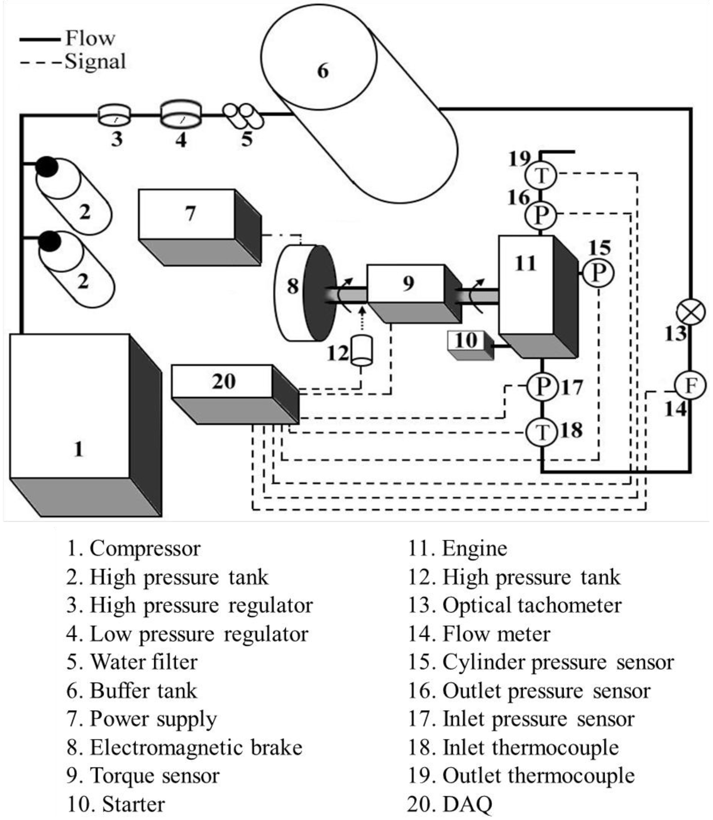
18]. The cam mechanism can provide a faster response, and sustains a higher operating pressure than electric actuators. The cam profile was modified to be conjugate to change the engine from 4-stoke to 2-stroke operation. However, this modification of the cam profile reduced the lift of the valve movement from 5 to 2 mm, and consequently restricted the air flow rate during engine operation. From the modified cam profile, the intake valve opens at 0° crank angle and closes at 150°, whereas the exhaust valve opens at 170° and closes at 360°. The starting motor of the IC engine was kept to drive the engine if the intake valve was not open when starting. The intake port of the engine was connected to a high-pressure air supply system. During experiments, a high-pressure air system integrated with a 300 bar air compressor (MACO BAM06, Comp Air, Gardner Denver, Quincy, IL, USA) and high pressure air cylinders provided a steady compressed air source at various pressures. Pressure regulators adjusted the 300 bar compressed air stored in the cylinders to a lower pressure for various experimental conditions (from 5 to 9 bar) through two stages. The compressed air was stored in a 400 L buffer tank to provide a steady air flow rate during the experiments. The test bench includes a 50 N·m torque transducer (TPS-A-50NM, KYOWA, Tokyo, Japan) combined with an electromagnetic brake to measure the power output from the test engine. The electromagnetic brake applied a load varying from 0 to 50 N·m. Two pressure transducers (PVL and PVB, KYOWA) and two k-type thermocouples were installed at the inlet and exit of the engine respectively to monitor the pressure and temperature variations during the test. To record the cylinder pressure during the experiments, the spark plug that was no longer used for the compressed air operation was replaced by a high pressure sensor (PHL-A-2MP-B, KYOWA). A flow meter (TF-4150, Tokyo Keiso Co. LTD, Tokyo, Japan) was installed at the engine inlet to record the flow rates. An optical counter (FS-N11N, Keyence, Osaka, Japan) acquired the location of piston in the cylinder during the engine operation. All data acquired from the experiments were transferred to a data acquisition unit (GL-900, GRAPHTEC, Yokohama, Japan) for recording and further analysis.
Figure 1 shows the schematic of compressed air engine test bench, and
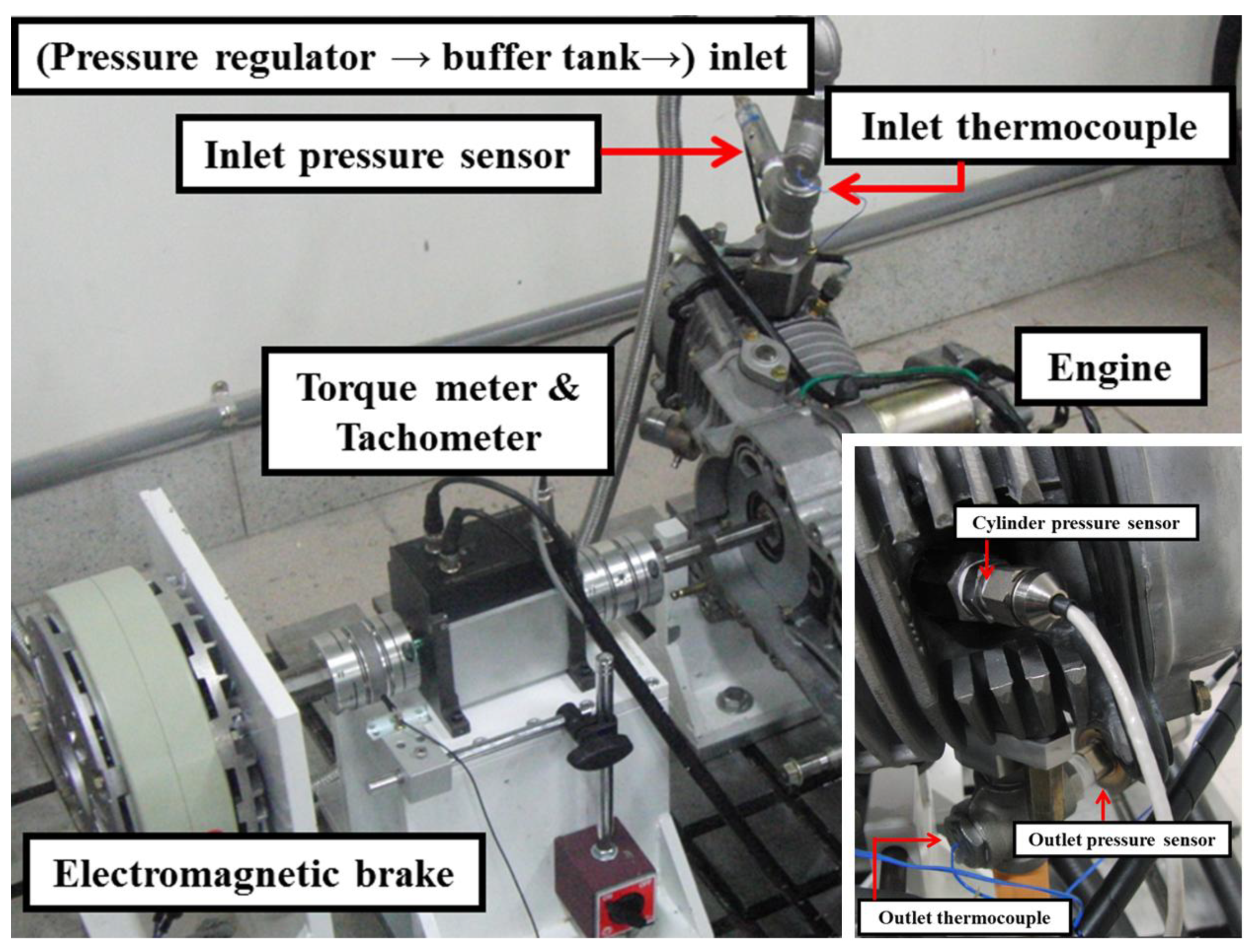
Figure 2 shows a picture of the experimental setup.
After the engine was installed, the intake and exhaust valves were examined for possible leakage under high-air-pressure operation. The intake valve design in conventional IC engines prevents the gas leaking from inside the cylinder during the combustion process (i.e., the pressure inside the cylinder is considered higher than that in the intake port). However, in air engines, compressed air feeding from the intake port pushes the piston down instead of high-pressure gas generated from combustion.
Furthermore, the pressure outside the intake valve (in the intake port) is always higher than that inside the cylinder. The springs that were originally installed in the cam drive from the manufacturer cannot lock the intake valve in the closed position during the exhaust process. Consequently, high-pressure air leaks from the intake valve during the exhaust process, and the cylinder pressure is unable to decrease to ambient pressure. Furthermore, the air leaking into the cylinder during the exhaust process reduces torque output while the piston moves from the BDC to TDC.
Figure 1.
Experimental setup of the compressed air engine test bench.
Figure 1.
Experimental setup of the compressed air engine test bench.
Figure 2.
Photograph of the experimental compressed air engine setup.
Figure 2.
Photograph of the experimental compressed air engine setup.
The intake valve leakage was examined by locking the engine in the exhaust process (i.e., with the intake valve closed and exhaust valve open) and recording the air flow through the cylinder. The leakage was measured up to 1800 L/min when the inlet pressure was 9 bar. The leakage of the intake valve was thus close to the flow rate in the experiments, and it seriously affected the performance of the compressed air engine. The exhaust valve leakage was examined when the engine was locked in the intake process, and no leakage was observed. The original design of installing the spring in the exhaust valve can prevent the gas leakage during the engine operation. To solve the problem of leakage from the intake valve, a stronger spring was installed to replace the original one. No leakage was observed for an inlet air pressure of up to 9 bar after the replacement.
4. Results and Discussion
The power outputs from the modified air engine were measured at air pressures ranging from 5 to 9 bar, and the pressure and temperature data were measured at various locations including the inlet, exit, and cylinder. This study also presents a pressure and temperature evaluation inside the cylinder at various crank angles to address the issues of air intake and exhaust and low temperature.
4.1. Torque and Pressure Measurements on the Compressed Air Engine in One Cycle
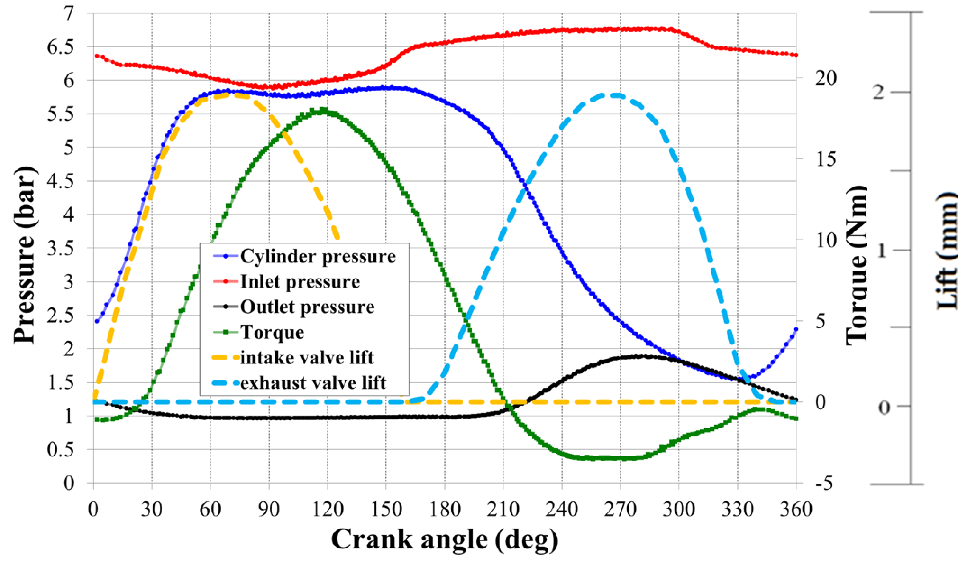
Figure 3 shows cylinder pressure, inlet pressure, outlet pressure and torque variation acquired at different crank angles at 7 bar supply pressure and 800 rpm. These data were phase-averaged at the same crank angle after 200 cycles.
Figure 3.
Cylinder pressure, inlet and outlet pressure, torque variation and valve movement in one engine cycle.
Figure 3.
Cylinder pressure, inlet and outlet pressure, torque variation and valve movement in one engine cycle.
The intake valve and exhaust valve lift were also plotted to provide the valve position reference at various crank angles. The intake valve opens at the beginning of the engine cycle, and closes completely at a crank angle of 150°, leaving 20° for isentropic expansion. However, this isentropic expansion is not obvious in the acquired cylinder pressure data because of a small cylinder volume change when the piston moves from 150° to 170°. The exhaust valve opens at 170°, and the early opening of exhaust valve is to ensure the easy discharge for the exhaust process originally designed for the IC engine. The exhaust valve closes completely around 340°. The cylinder pressure increases with the intake valve opening until it reaches 6 bar, whereas the inlet pressure drops from 6.3 to 6 bar. The inlet pressure is only 6.3 bar when the supply air pressure (i.e., the pressure indicated in the buffer tank) is controlled at 7 bar. The difference between inlet pressure and supplying air pressure is caused by the air velocity (dynamic pressure) and the pressure loss between the tank and tubing. The supply air pressure is the plenum pressure measured in the buffer tank, and the inlet pressure is the static pressure measured at the inlet port. The torque begins to increase at approximately 30° after the intake valve opens. This is because of the alignment of the piston and connecting rod in the crankshaft system. The inlet pressure recovers back to 6.7 bar after the intake valve closes. The cylinder pressure starts decreasing while the exhaust valve opens. The cylinder pressure decreases to 2.5 bar at the maximum opening of exhaust valve, and the outlet pressure increases to close to the cylinder pressure. The cylinder pressure increases again after the exhaust valve closes. This compression process inside the cylinder requires work, and therefore, reduces the overall power output.
4.2. Power Measurements of the Compressed Air Engine
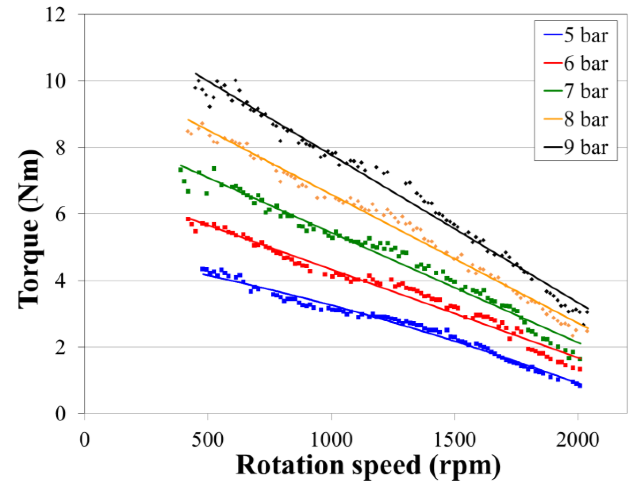
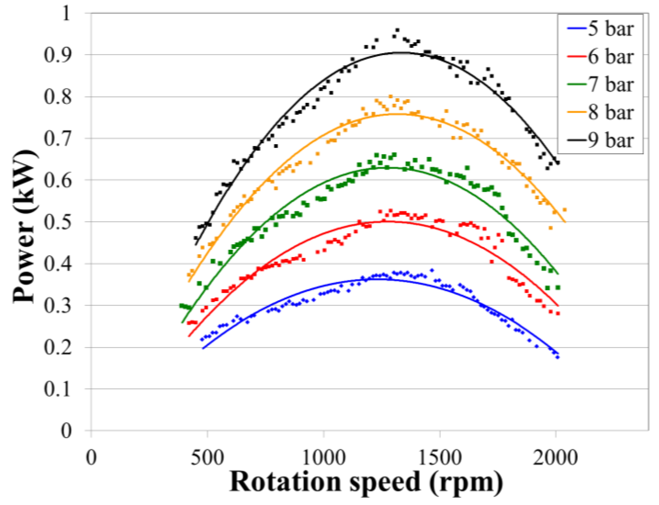
The torque and power output from the compressed air engine were evaluated (averaged after 200 cycles) at the test bench at various supplied air pressures, as shown in
Figure 4 and
Figure 5. The maximum supplied air pressure during the experiments was limited to 9 bar, which is the highest pressure that small/medium size air compressors can provide [
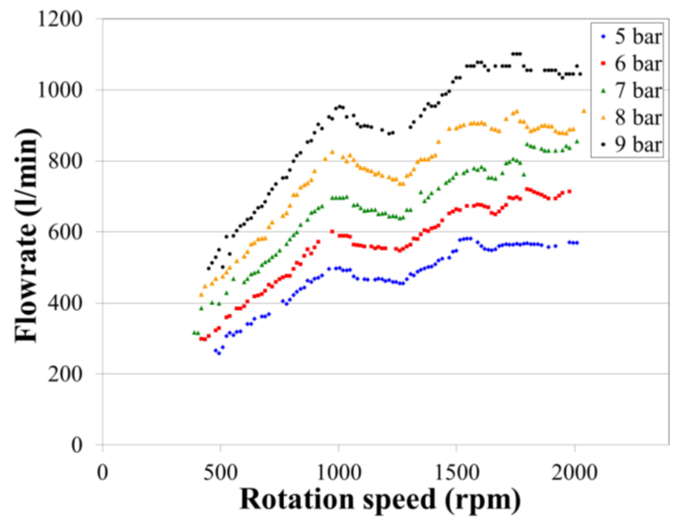
19]. The highest torque 9.99 N·m was measured at 9 bar and 465 rpm, and the highest power output of 0.96 kW was obtained at 9 bar and 1320 rpm. The flow rates of the compressed air engine (supplying pressure: 9 bar) vary from 500 L/min to 1050 L/min as the rotation speed changes from 500 rpm to 2000 rpm. The highest torque and power output were obtained at the highest supplied air pressure, indicating that the highest air pressure provides the highest force applied on the piston.
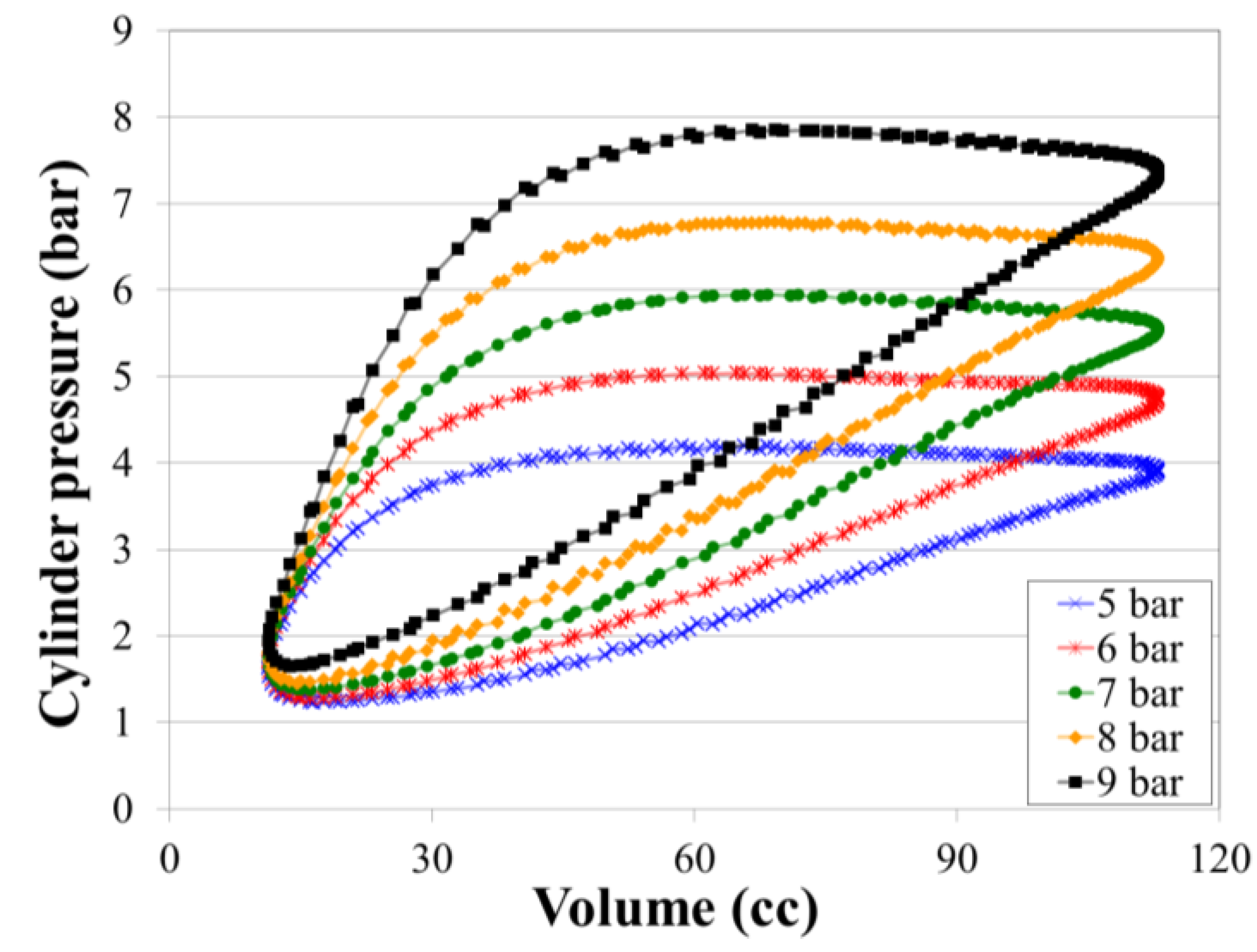
Figure 6 shows the P-V diagrams acquired at 1200 rpm at various supplying pressures. The area within the P-V diagram indicates the work output from the piston movement in the engine cycles. Both the enclosed areas in the P-V diagrams and the cylinder pressure during the intake process increase while the supplying air pressures increase. However, the minimum pressure in the cylinder during exhaust pressure also increases as the supplying air pressure increases. A higher cylinder pressure will easily encounter choke flow during exhaust process and restricts the discharging flow rate, leading to a higher residual pressure in the engine.
Figure 4.
Torque output of the compressed air engine at different rotation speeds and supplied air pressures.
Figure 4.
Torque output of the compressed air engine at different rotation speeds and supplied air pressures.
Figure 5.
Power output of the compressed air engine at different rotation speeds and supplied air pressures.
Figure 5.
Power output of the compressed air engine at different rotation speeds and supplied air pressures.
Figure 6.
P-V diagram acquired during experiments at 1200 rpm and different supplied air pressures.
Figure 6.
P-V diagram acquired during experiments at 1200 rpm and different supplied air pressures.
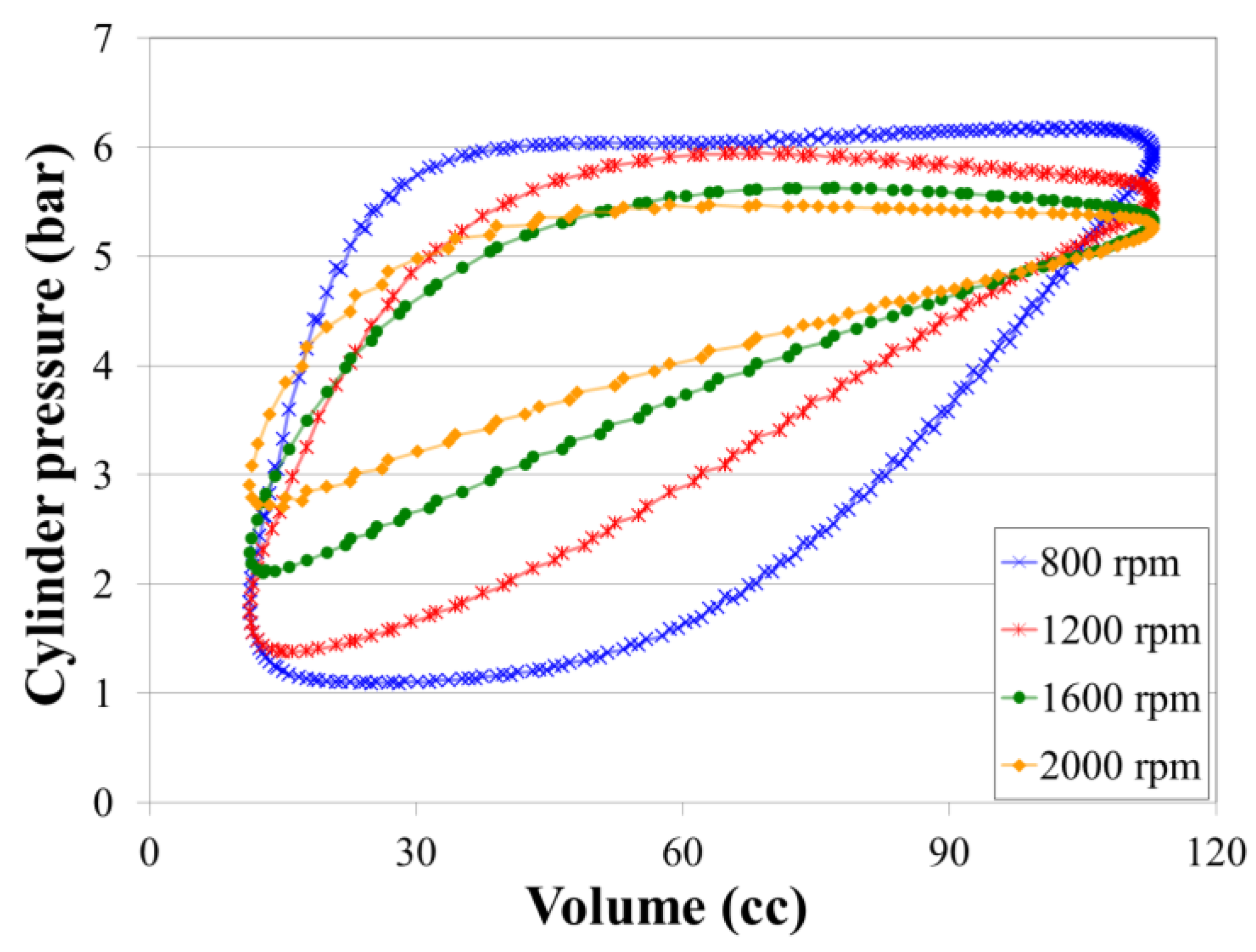
Figure 7 shows the P-V diagrams acquired at 7 bar supply pressure and various rotation speeds. The maximum cylinder pressures decreases at higher rotation speeds during the intake processes because the compressed air does not have enough time to fill the cylinder. The cylinder pressure during the exhaust process also increases at higher rotation speeds, and takes more time to decay. This is because the compressed air has less time to discharge from the cylinder. The rotation speed has greater effect on the residual pressure inside the cylinder than the supplied air pressure.
Figure 7.
P-V diagram acquired during experiments at 6 bar and different rotation speeds.
Figure 7.
P-V diagram acquired during experiments at 6 bar and different rotation speeds.
To further study the effects of the limited lift during the intake and exhaust processes, this study uses simplified thermodynamic models to calculate the pressure variation inside the cylinder by using commercial MATLAB software (The MathWorks, Inc., Natick, MA, USA). The calculations in this study are based on the ideal gas law, with the thermodynamic models and the assumption of no friction. The sinusoidal equation was used for estimating the valve movement. The area for the flow passage is calculated by the circumference of the valve and distance between the port and valve, and it changes with the valve movement.
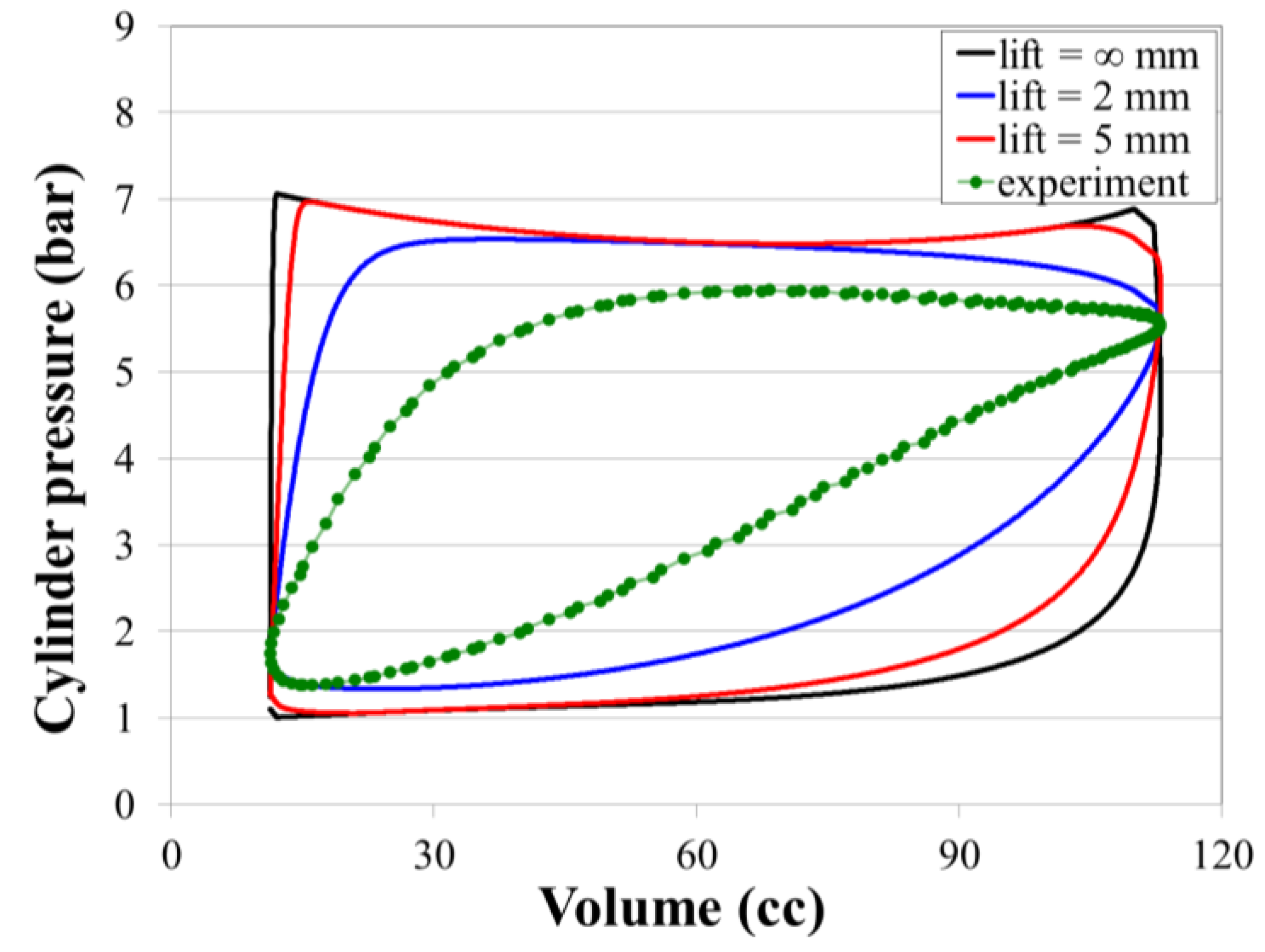
Figure 8 shows the pressure variation at various lifts, as estimated by the MATLAB program at 7 bar and 1600 rpm, and provides a comparison of these results with the acquired experimental data. An infinite lift represents no area constraint from the valve movement, and the area for the flow passage was fixed as the diameter of the port size. Without the valve lift constraint, the pressure increases immediately after the intake valve opens. The pressure decreases slightly while the piston moves to the BDC because of the limited air flowing into the cylinder which does not suffice to fill the increased space during expansion. If the valve lift decreases to 2 mm, the intake air flow decreases further, and the pressure gradually increases. Because of the lower flow rate, the pressure decrease during volume expansion is not obvious. The pressure decrease during the exhaust process with a 2 mm valve lift is not as much as that at a larger valve lift, and a higher residual pressure inside the cylinder appears in both the experimental data and MATLAB calculations. The pressure variation estimated by the MATLAB calculation is similar to the experimental data. However, because of the simplified assumptions applied in the thermodynamic models and the exclusion of actual flow behavior (e.g., flow separation near the valve or friction loss), the exact actual pressure data differ.
Figure 8.
P-V diagram acquired during experiment and estimated with simplified thermodynamic models for different lifts at 7 bar and 1600 rpm.
Figure 8.
P-V diagram acquired during experiment and estimated with simplified thermodynamic models for different lifts at 7 bar and 1600 rpm.
4.3. Pressure and Temperature Measurements of the Compressed Air Engine
To better understand the pressure and temperature variations during the engine operation, pressure and temperature sensors were installed at the engine inlet and exit and inside the cylinder of the engine.
Figure 9 and
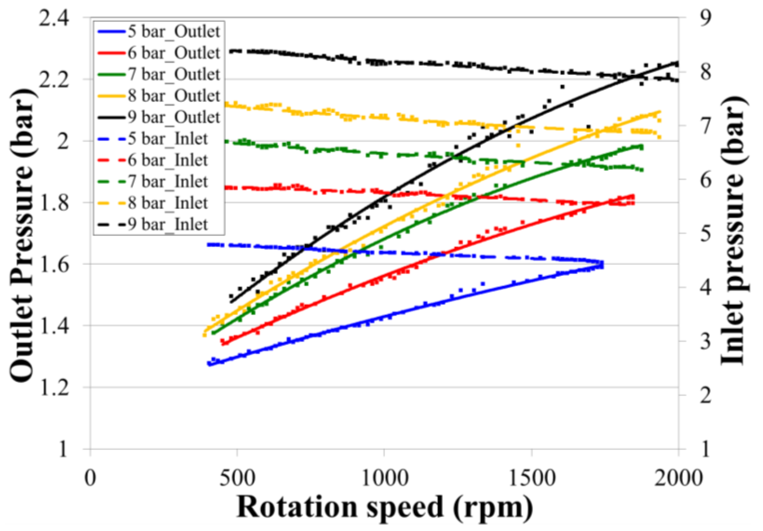
Figure 10 show the measured pressure and temperature variations at the engine inlet and outlet at various rotation speeds and supply pressures, respectively. Under a pressure of 9 bar, the inlet pressure slightly drops by approximately 0.5 bar at low rotation speed (approximately 500 rpm), and continues to decrease as the rotation speed increases. Under the same operating conditions, the outlet pressure increases from 1.5 bar at a rotation speed of 500 rpm to 2.25 bar at 200 rpm. This increasing of outlet pressure at higher rotation speeds indicates less time for air expansion inside the cylinder before discharging, and shows that part of the compressed air energy is wasted without being used. The wasted compressed air energy could be reused if additional cylinders were attached (split-cycle design) [
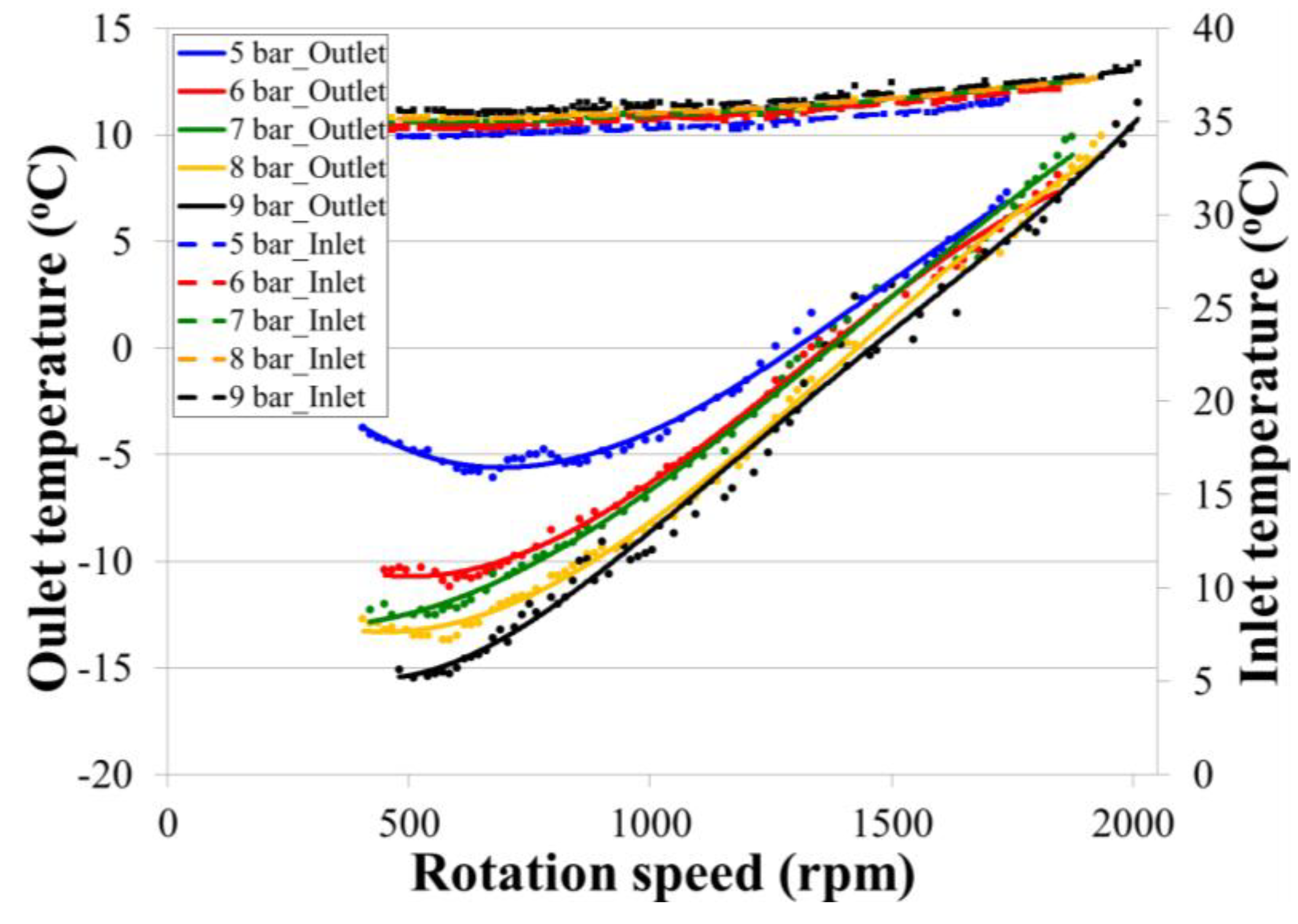
20]. The temperature recorded at the engine inlet is relatively steady and close to the room temperature of 36 °C. However, the outlet temperature drops to −15 °C at 500 rpm at 9 bar air pressure. The temperature is expected to decrease further at pressures higher than 9 bar, which will cause serious lubrication and sealing problems in the engine. The outlet temperature starts increasing as the rotation speed increases, and the outlet temperature reaches 35 °C while the rotation speed exceeds 1800 rpm. This is because of the reduced time for air expansion within the cylinder at high rotation speeds, and the heat generated from the friction between piston and cylinder.
Figure 9.
The inlet and outlet pressure variation at different rotation speeds and supplying air pressures.
Figure 9.
The inlet and outlet pressure variation at different rotation speeds and supplying air pressures.
Figure 10.
The inlet and outlet temperature variation at different rotation speeds and supplying air pressures.
Figure 10.
The inlet and outlet temperature variation at different rotation speeds and supplying air pressures.
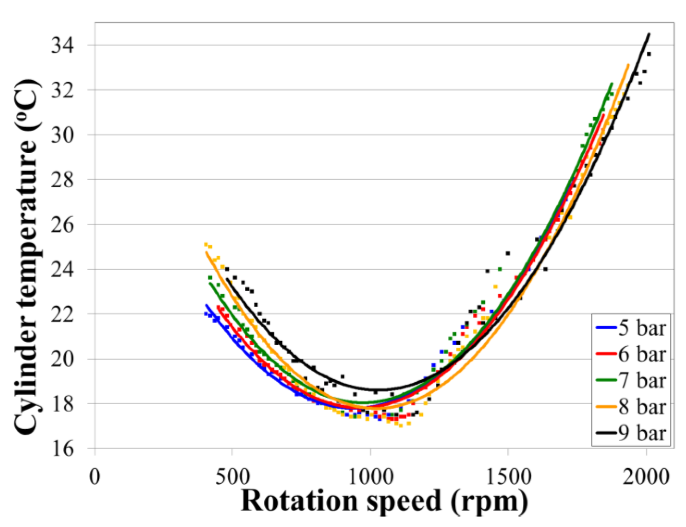
Figure 11 shows that the temperature inside the cylinder drops to 18 °C from room temperature because compressed air expands inside the cylinder. The cylinder temperature starts rising while the rotation speed exceeds 1000 rpm because of friction heat. The outlet temperature is generally lower than the cylinder temperature because of the second expansion of compressed air during discharging.
With the acquired pressure data at the inlet of the engine, the efficiency η of the air engine during operation can be calculated by dividing the measured rotation speed and torque by the inlet pressure and flow rate:
where
τ is the torque and
ω is the rotation speed of the engine acquired during experiments.
Pin is the inlet pressure, and
Q is the flow rate of the compressed air.
Figure 11.
Cylinder temperature variation acquired during experiments at 6 bar and different rotation speeds.
Figure 11.
Cylinder temperature variation acquired during experiments at 6 bar and different rotation speeds.
Figure 12 shows the acquired air flow rate at various pressure and rotation speeds.
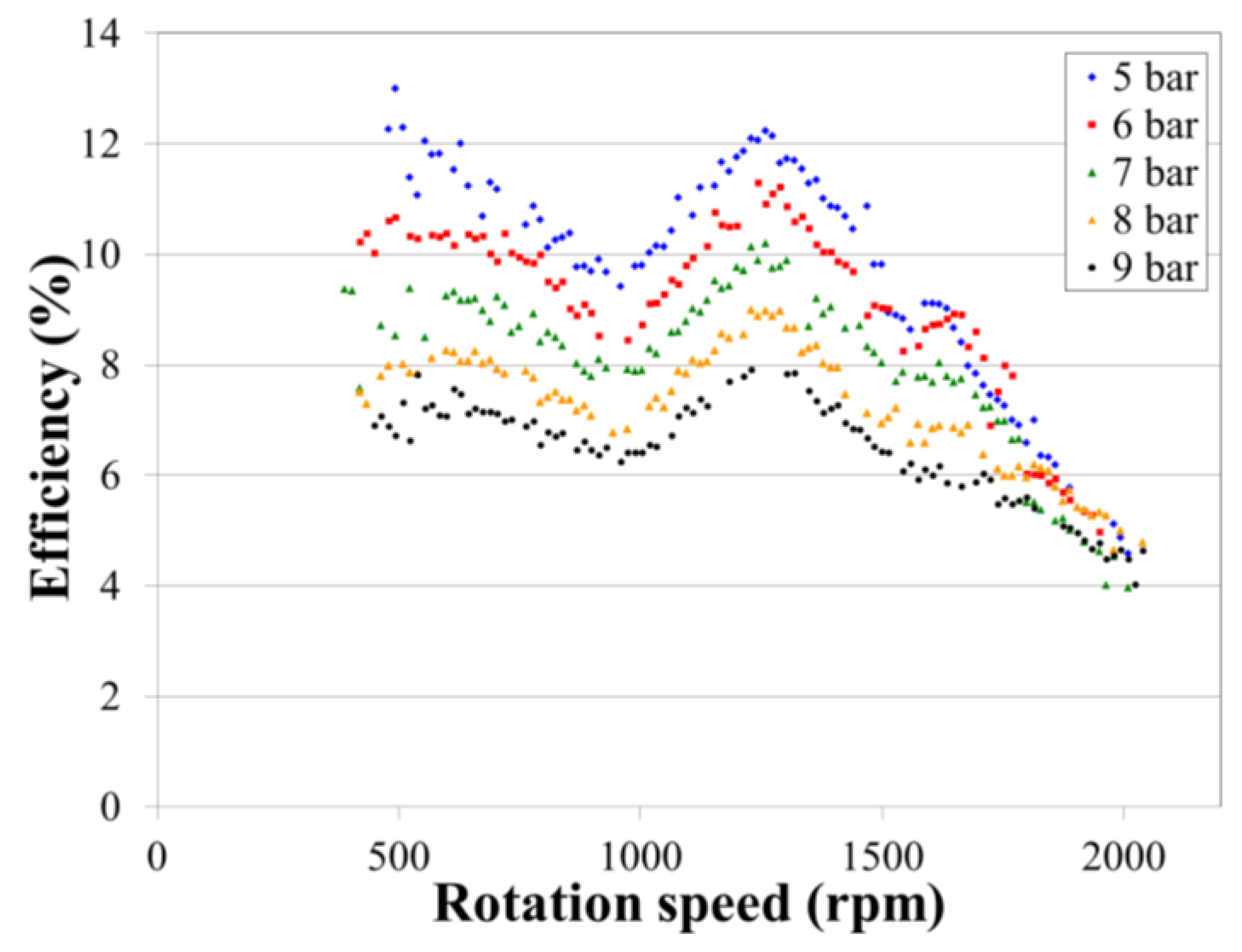
Figure 13 shows the calculated efficiencies under various experimental conditions. The highest efficiency (approximately 13%) is obtained at a low supply pressure of 5 bar and rotation speed less than 1500 rpm. A higher supply pressure can increase the power output of the compressed air engine, but the compressed air cannot fully expand inside the cylinder; thereby reducing the efficiency. The compressed air engine operating at high rotation speeds shows similar characteristics but lower efficiency. The calculated engine efficiency decreases at a low rotation speed, recovers at rotation speeds between 1000 and 1200 rpm, and then continues to decrease at a higher rotation speed. This observation, which shows a similar situation as the flow rate measurement, is attributed to the increased engine vibration which starts at 1,000 rpm and pressure wave propagation in the hose at the intake port [
21,
22].
Figure 12.
The acquired flow rate of the compressed air engine at different rotation speeds and supplied air pressures.
Figure 12.
The acquired flow rate of the compressed air engine at different rotation speeds and supplied air pressures.
Figure 13.
The calculated power efficiency of the compressed air engine at different rotation speeds and supplied air pressures.
Figure 13.
The calculated power efficiency of the compressed air engine at different rotation speeds and supplied air pressures.
5. Conclusions
This study presents the power output examination and pressure/temperature measurements of a piston-type compressed air engine to be installed on vehicles as a main or auxiliary power system. Results show that the compressed air engine, which was modified from a commercially available IC engine, can be operated at an air pressure from 5 to 9 bar and provide 0.96 kW power output and 9.9 N·m torque. The power output was measured under the situation of a small lift of intake and exhaust valve which is the consequence of modification from a 4-stroke to a 2-stroke engine. Although the power output is not as much as that of conventional IC engines using gasoline fuel, the torque generated from the compressed air engine is greater than that obtained from an IC engine. The air consumption (flow rate) of current air engine is low, at approximately 1050 L/min, which limits its power performance. The overall power performance and torque output could be further improved by adopting a larger intake and exhaust valve openings. The temperature inside the engine was monitored during the operation, and low temperatures were recorded. The cylinder temperature will continue to decrease if using a higher supply pressure than the pressure applied in current study, causing problems of lubrication and sealing between the piston and cylinder. The efficiency of the compressed air operation is approximately 13% at 5 bar supplying air pressure while the rotation speeds is below 1500 rpm. An approximately 2.25 bar exhaust air pressure occurs when operating at 9 bar supplying air pressure and 2000 rpm, showing that the under-expanded compressed air inside the cylinder reduces the efficiency. An increase of exhaust air pressure is expected at higher operating pressures or rotation speeds. Therefore, it is necessary to recycle this energy for practical applications in vehicles. The residual air pressure disposed during the exhaust process could be reused if additional cylinders are attached (i.e., adopting a split-cycle design). The exhaust air with a pressure of approximately 2.25 bar can be expanded with additional cylinders, producing extra work. The concept of a split-cycle design can improve the energy usage of compressed air, thereby extending the duration of compressed air engines used in vehicle applications.


