Abstract
Constant power loads (CPLs), interfaced through active rectifiers can be used for improving the stability of induction generator (IG)-based wind turbines under balanced grid voltage dips by providing the reactive power. Under asymmetrical grid faults, the negative sequence voltage produces additional generator torque oscillations and reduces the lifetime of the installed equipment. This article explores the possibility of using a CPL for mitigation of unbalanced voltage dips in an AC distribution system in addition to consuming a constant active power. Unbalanced fault mitigation as an ancillary service by the load itself could greatly increase the stability and performance of the overall power system. A CPL control structure, capable of controlling the positive and negative sequence of the grid voltage is suggested. The simulation results clearly indicate the effects of compensating the positive and negative sequence of the grid voltage on the performance of IG based wind turbines. The maximum Fault Ride Through (FRT) enhancement has been given priority and is done by the compensation of positive sequence voltage. The remaining CPL current capacity is used to compensate the negative sequence voltage in order to reduce the additional torque ripples in the IG.
1. Introduction
Distributed energy resources (DERs), based on mainly renewable energy represent only a small part of the present day power infrastructure and have a small impact on the performance and quality of the electrical grid [1]. However, in order to achieve the targets related to emissions reduction and energy independence, governmental efforts are being carried out to significantly increase the share of renewable energy in local and regional utility grids. Deregulation of the power market will also contribute to a growing use of distributed generation from renewable energy sources.
Wind energy has appeared as the fastest spreading source of renewable energy and will continue to grow in the near future. It is also the most mature and cost-effective renewable energy technology available today [2,3]. IG-based wind farms represent a substantial 30% of the installed wind power in Europe [4] and enhancing their FRT capability is essential in order to improve the power system stability and reliability [5,6]. Typical FRT requirements demand that the wind farm remains connected to the power system for voltage levels as low as 5% of the nominal grid voltage [2,7]. Although IG provides a cost effective solution for wind turbines, it also consumes reactive power from the grid. During a grid voltage sag it consumes large amounts of reactive power as its speed deviates from the synchronous speed, resulting in a voltage collapse and further fault propagation within the electrical network. Most of the work about FRT enhancement of the IG based wind turbine is related to balanced grid voltage sags. However, in general more than 90% of the grid faults result in unbalanced voltage sags with both positive and negative sequence components [6]. Unbalanced voltage problems generate heating in the machine windings and toque oscillations, leading to mechanical vibrations and noise.
Proliferation of solid-state devices in AC power systems to improve the performance and flexibility has resulted in widespread use of power electronic converters at the distribution level [8]. Power electronic (PE) load interfaces, when tightly regulated, draw a constant active power from the utility and behave like CPL. They are adaptive to fluctuations in the grid voltage at its terminal and always keep the input power constant [8,9,10,11,12]. The number of this kind of loads has been rapidly growing and will continue increasing in the near future. Battery chargers for electric vehicles, motor drives and large rectifiers for DC loads are a few examples of CPLs. The constant power characteristic in CPLs causes negative resistance instability at their input terminals. The role of CPLs in AC distribution systems from the stability point of view has been investigated in [13,14]. It has been reported that CPLs can be successfully used to increase the margins to prevent voltage collapse.
Many variable-speed type large wind turbines utilize the doubly fed induction generator (DFIG) configuration with back to back rotor and grid side converters. It has been observed that DFIGs experience inherent difficulties to ride through grid faults due to the high voltage that can be induced in the rotor circuit. In [15], different methods for the coordinated control of grid and rotor side converters for unbalance voltage compensation have been proposed. However, positive sequence voltage compensation is not discussed. In the absence of a power electronic interface (PEI) between the generation system and the utility grid, the adjustable reactive power control cannot be performed and a dedicated static synchronous compensator (STATCOM) is required to fulfill the grid code requirements. Many practical strategies of STATCOM reactive power control under asymmetrical grid faults and load unbalances have been discussed in [6,16] and proved to be very effective. However, the installation of a dedicated switching compensator or a STATCOM is not very cost effective.
This paper, for the first time, proposes the application of a tightly regulated PE load interface or a CPL that is connected to a squirrel cage IG-based wind turbine and is used for the mitigation of unbalanced grid voltage dips. The main contribution of this work is based on the fact that a dedicated device (STATCOM or DFIG) is not needed for FRT enhancement and an industrial motor drive or any other CPL available in the vicinity of the IG based wind farm can be utilized to provide this additional service. The simulation results indicate that positive sequence voltage compensation by CPL helps to avoid the complete voltage collapse and increases the stability of the wind turbine, while the negative sequence voltage compensation reduces the torque oscillations, thereby increasing the lifetime of the generator drive train.
2. Constant Power Load
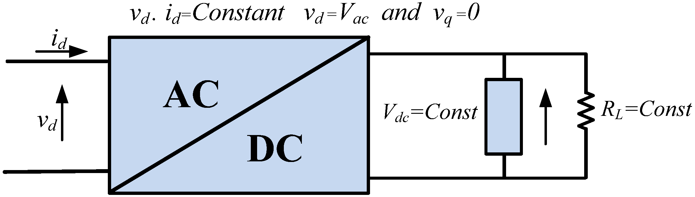
Generally, CPL is connected to the AC distribution system via a controlled or uncontrolled rectifier. In our case, CPL is a tightly regulated voltage source converter (VSC) as shown in Figure 1. VSC uses six IGBT switches with anti-parallel diodes for reverse current conduction. Like many other non-linear loads the resistance of the CPL depends on the applied voltage at its terminals. Many of the home appliances are loads with AC/DC converters inside, feeding an internal part that works on a constant DC voltage [11]. The control system of these AC/DC converters controls the direct voltage Vdc in a way that it becomes independent of the applied grid voltage. This means that the AC power is independent of the value of grid voltage [17]. Under abnormal voltage conditions, the operation of the internal controller demands the VSC to draw more/less grid current to maintain a constant active power at the converter input, that is:
where Pin is the input active power and id+ and vd+ are the positive sequence active components of the AC side current and voltage respectively under balanced voltage dips . Since the input active power to the converter remains constant in a wide range of operating conditions, provided that the controller works properly, the vi characteristics of the CPL is investigated by first considering the incremental input resistance RCPL [18]. This value is given by the ratio of small signal changes in input voltage over small signal input current:

Figure 1.
Basic model of a CPL.
Figure 1.
Basic model of a CPL.
RCPL demonstrates the negative resistance seen from the AC side. This small signal non-linear input resistance can be calculated by considering the input power equal to output power that is, Pin = Pout = v.i and v = Pin/i.
Differentiating the voltage with respect to the current yields negative input resistance:
Figure 2 demonstrates the negative resistance characteristic of the CPL and confirms the inverse relationship that holds between voltage and active current under balanced voltage dip conditions. It can also be seen that the destabilizing effects of the negative resistance can be minimized when the CPL is able to inject the reactive current iq+ into the power system. The reactive injection leads to a small increase in AC side voltage at the CPL terminal and the active component of the current decreases to keep the input power constant.
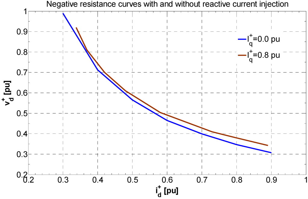
Figure 2.
Negative resistance characteristics of a CPL.
Figure 2.
Negative resistance characteristics of a CPL.

CPL Control Structure
The control strategy implemented for VSC is based on vector control method in a synchronous reference frame (SRF) to achieve an independent control of active and reactive powers. It is a cascade control scheme with inner proportional integral (PI) current controllers in a rotating SRF with grid voltage orientation. The transfer function of the PI controllers can be expressed as:
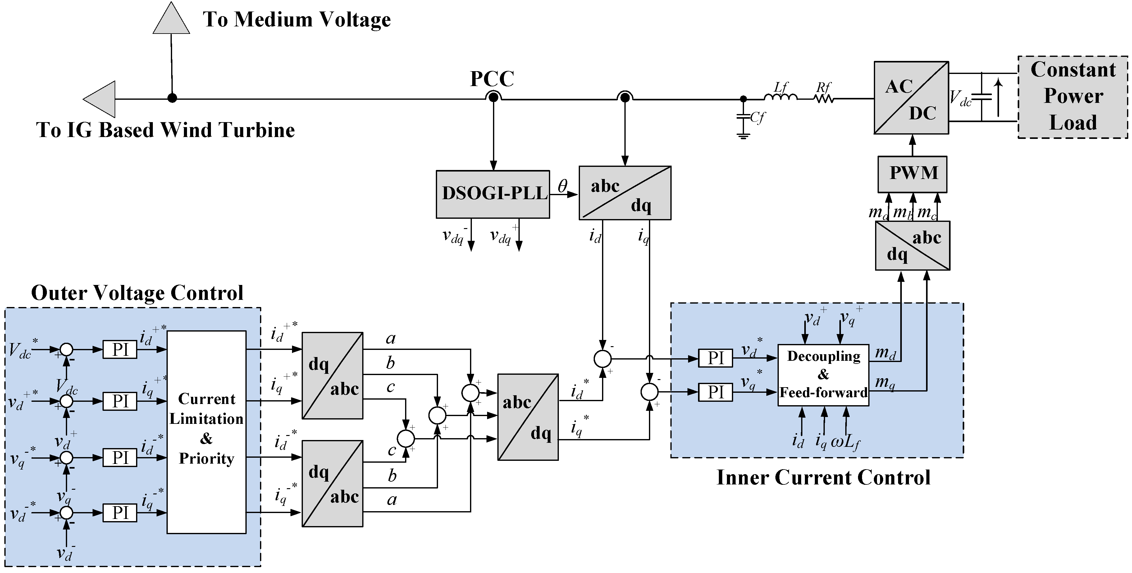
In order to achieve a decoupled control of active and reactive components of current the cross coupling terms are cancelled out by the feed-forward. The overall control structure is represented in Figure 3. The outer control loops are designed to control the DC link voltage and the positive and negative sequence of the ac voltage at the point of common coupling (PCC). The parameters of the PI controllers given in (4) are selected to achieve the optimal performance of the control loops. The inner current controllers are tuned using the modulus optimum technique and the tuning of the outer voltage controllers is based on the symmetrical optimum method as presented in [13]. A precise sequence separation of the PCC voltage into positive and negative sequence components is required. A phase lock loop (PLL) based on dual second order generalized integrator (DSOGI) has been employed for this purpose [19,20,21]. Using the DSOGI-PLL sequence separation scheme, the positive and negative sequence of the voltage appear as DC values in SRF and can be easily controlled by using PI controller. The current references generated by the outer PI controllers must be limited to the maximum current rating of the CPL for safe operation and to avoid tripping of the converter. Therefore, a current limiting scheme has been introduced. The priority has been given to the positive sequence reactive current i+q to compensate the positive sequence voltage, thereby making sure the maximum FRT enhancement of the IG based wind turbine. The remaining current capacity of the CPL is used to compensate the negative sequence voltage in order to reduce the torque pulsations during the asymmetrical grid fault. Switching of the IGBTs is done with pulse width modulation (PWM) at a frequency of 5 kHz. The implemented load is a dependent current source that uses a manually specified value of power divided by measured DC voltage. Filter inductance Lf and resistance Rf are chosen to be 5% and 1% of the base impedance respectively. The filtering capacitor Cf prevents the harmonics caused by switching of the IGBTs from entering into the grid side.

Figure 3.
CPL control structure with independent control of positive and negative sequence voltages at PCC.
Figure 3.
CPL control structure with independent control of positive and negative sequence voltages at PCC.
Positive and Negative Sequence Calculation in SRF
In the proposed control structure, a frequency adaptive positive and negative sequence detection technique named as DSOGI-PLL has been mentioned. This technique translates the three-phase voltage from the abc to stationary αβ reference frames. A dual SOGI-based quadrature signals generator (QSG) is employed for filtering and obtaining the 90-degree shifted versions from the αβ voltages. The SOGI-QSG scheme is shown in Figure 4 and its characteristic transfer functions are given by:
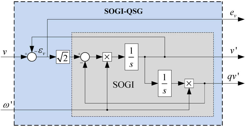
Figure 4.
SOGI-QSG Scheme.
Figure 4.
SOGI-QSG Scheme.

These signals act as inputs to the positive and negative sequence calculator (PNSC). The positive and negative sequence αβ voltages are then translated to the rotating SRF and a PLL (SRF-PLL) is employed to make the system frequency adaptive [20].
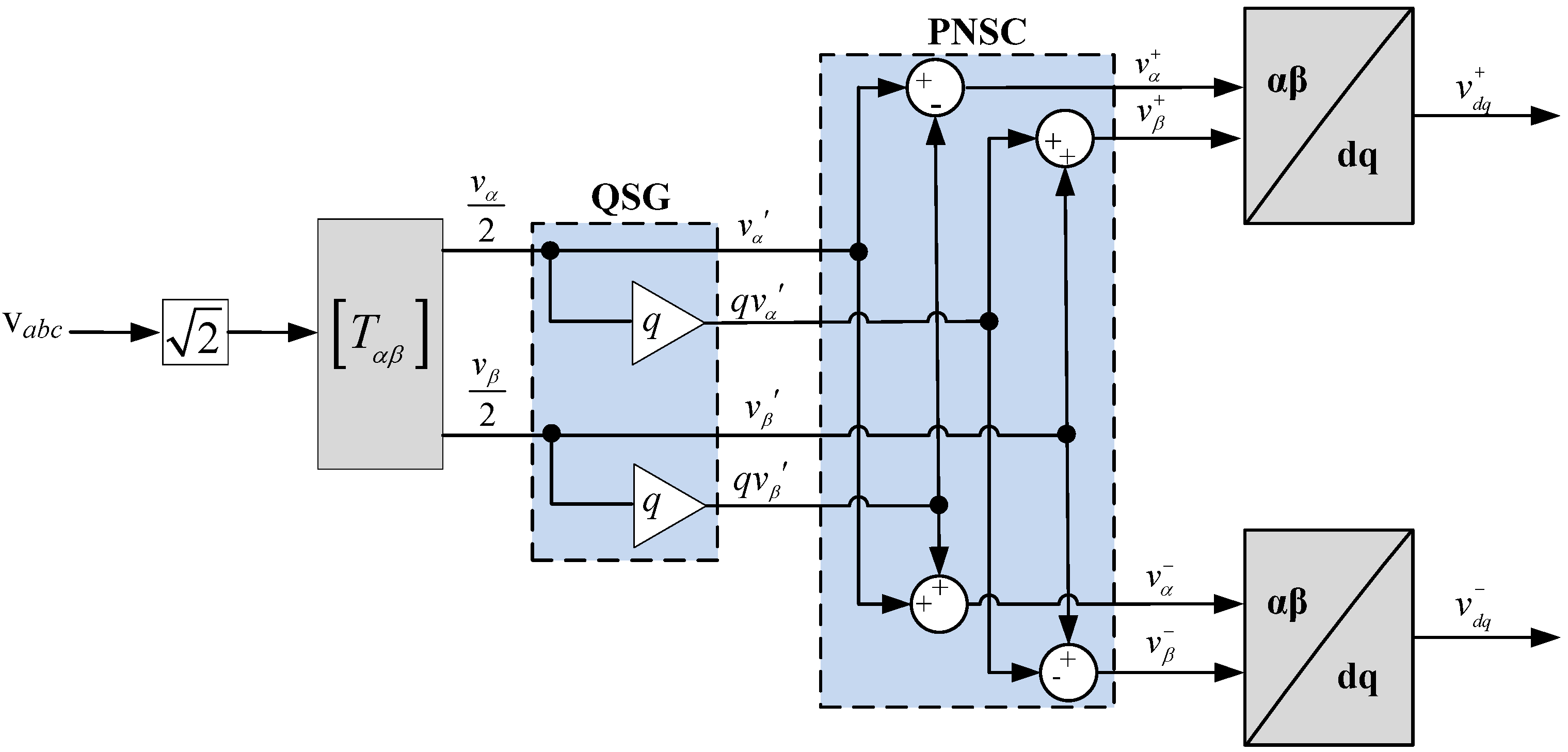
The instantaneous positive and negative sequence components, v+abc and v−abc of a generic voltage vector vabc = [va vb vc]T are written as [19,22]:
The instantaneous positive and negative sequence voltage components in stationary αβ reference frame are given by:
where q = e−j π/2 is a phase shift time domain operator to obtain in-quadrature version of an original waveform. The system of Figure 5 represents the QSG and PNSC used for the extraction of positive and negative sequence voltage.
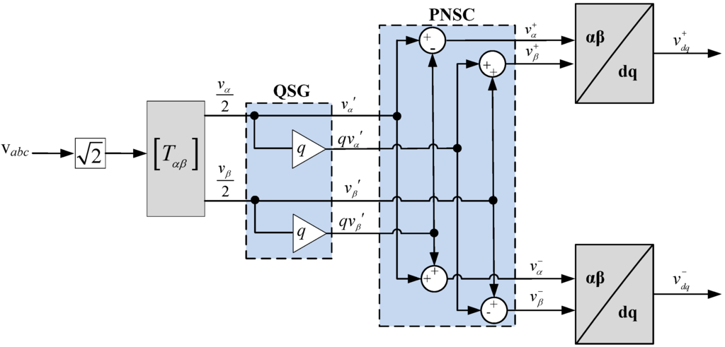
Figure 5.
Positive and negative sequence calculation for SRF.
Figure 5.
Positive and negative sequence calculation for SRF.
3. Impact of Voltage Sag on IG
Generally, IG has many advantages such as low price, robust design, overload handling and need for little maintenance. However, the biggest disadvantage is the uncontrollable reactive power consumption. The compensation for the reactive power consumption needs shunt capacitor banks at no-load [23,24]. Squirrel cage IGs easily become unstable under low voltage conditions as low terminal voltage increases the rotor slip and consumption of reactive power, thereby, further lowering the voltage which leads to disconnection of the turbine.
The torque T+ of the IG has a quadratic dependence on the positive sequence stator voltage magnitude [24], and can be represented by:
where Rs, Rr, Xs and Xr are the stator and rotor resistance and impedance parameters of the IG equivalent circuit, p is the number of pole pairs, s is the slip and ωs is the grid frequency. For a smaller voltage dip the IG may regain a stable operating point [24], but for a deep voltage dip the IG loses it torque control and may have to be disconnected from the grid due to overspeed or a voltage collapse may happen in the network due to high reactive power consumption.
Under the unbalance voltage conditions, the stator currents become unbalanced too and even a small amount of negative sequence voltage results in a very high negative sequence current , such that:
where Ls is the stator inductance, Is,N is the rated stator current and σ is the leakage factor. Average torque is not much affected by the negative sequence current; however, it causes the torque ripples of double grid frequency. The magnitude of the positive sequence torque and negative sequence torque T− can be represented by:
Due to the decreased positive sequence voltage magnitude, the average torque is reduced, leading to the acceleration of the generator. There are additional torque oscillations of the double grid frequency due to the negative sequence stator voltage resulting in heating of the stator windings and reduced lifetime of the turbine drive train. The average torque and the torque ripples can only be controlled independently if the CPL is able to control the positive and negative sequence voltages.
4. Structure of the Power System
The investigated power system is shown in Figure 6. It consists of a 750 kW wind turbine with a squirrel cage IG connected directly to the grid through a transformer and a 750 kVA CPL connected at the terminals. CPL is modeled as a controlled voltage source and is connected to the low voltage bus. The transformer is rated for wind turbine and CPL power. The main grid is a three phase AC source with internal impedance. The grid fault occurs at the medium voltage bus. The inductance Lg of the transmission line is assumed to be 1mH per kilometer [25]. The power system parameters in per unit (pu) are presented in Table 1. The power system has been modeled in PSCAD /EMTDCTM software.

Table 1.
Induction Generator, CPL and Grid Parameters.
| Induction Generator | |
| Base Apparent Power | 800 kVA |
| Rated Active Power | 750 kW |
| Rated Voltage (line to line) | 690 V |
| Stator resistance | 0.0092 pu |
| Stator leakage inductance | 0.1580 pu |
| Mutual inductance | 3.87 pu |
| Rotor mutual inductance | 0.0651 pu |
| Polar moment of inertia | 5 s |
| Mechanical damping | 0.008 pu |
| Constant Power Load | |
| Rated Power | 750 kVA |
| Rated Voltage (line to line) | 690 V |
| Filter Inductance Lf | 0.05 pu |
| Filter Resistance Rf | 0.01 pu |
| DC Link Voltage Vdc | 1126 V |
| Grid and Transmission Line | |
| Rated Voltage (line to line) | 22 kV |
| Rated Frequency | 50 Hz |
| Resistance | 0.84 pu |
| Inductance | 2.51 pu |
| Transmission Line Inductance Lg | 105.5 pu |
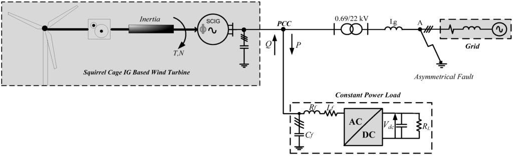
Figure 6.
System under study with squirrel cage IG connected to the grid and a CPL connected at the terminals.
Figure 6.
System under study with squirrel cage IG connected to the grid and a CPL connected at the terminals.

5. Results for Asymmetrical Grid Faults
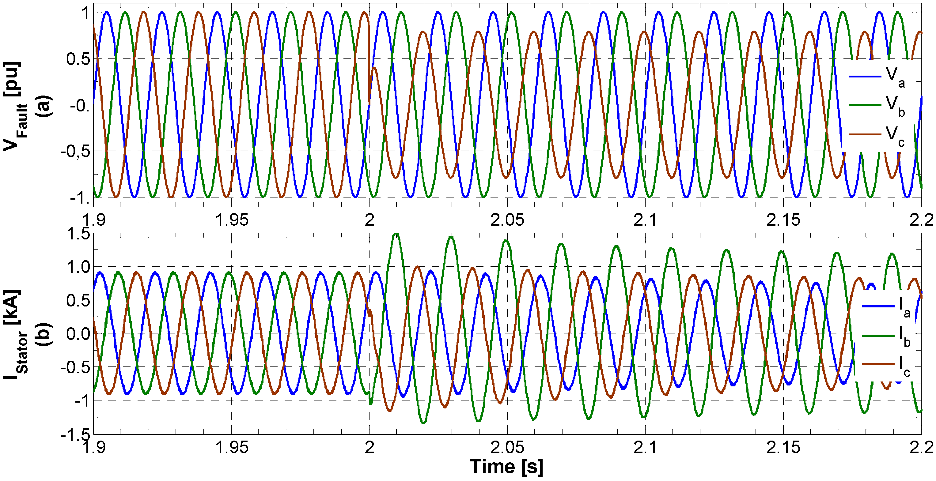
In this section, a comprehensive simulation study has been carried out to investigate the FRT capability of an installed CPL at the distribution level supplied by IG based wind turbine. CPL starts consuming 30% (225 kW) of the IG power at time t = 1 s. This has been done to achieve a steady state operating point for the IG. An asymmetrical fault (single phase amplitude falls to 78%) is simulated at the medium voltage bus as shown in Figure 6 at time t = 2 s for a duration of 1 second. The unbalanced grid fault results in highly unbalanced currents in the stator of the IG as shown in Figure 7.

Figure 7.
System voltages and currents. (a) Voltage at the fault; (b) IG stator currents.
Figure 7.
System voltages and currents. (a) Voltage at the fault; (b) IG stator currents.
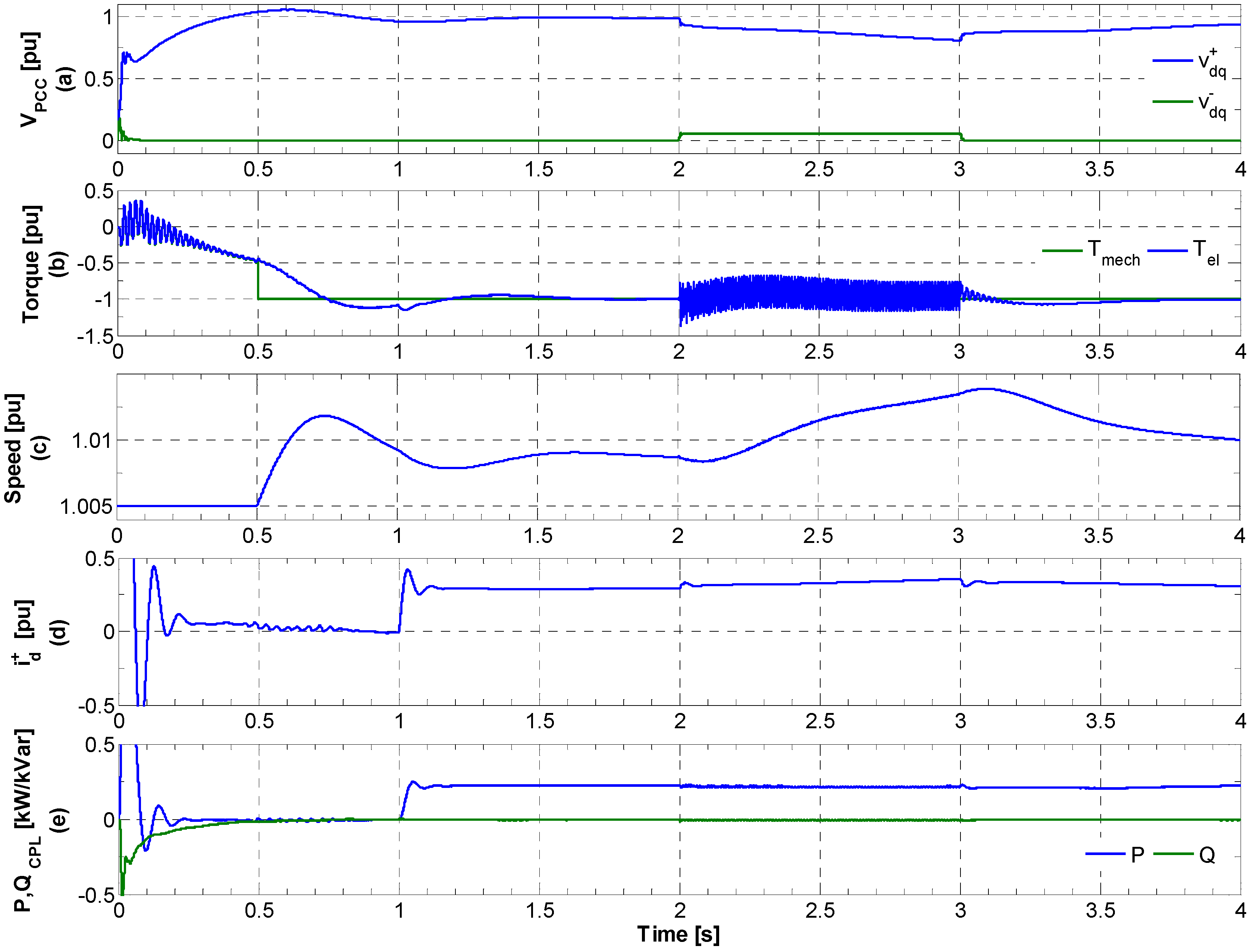
At the initial stage of the analysis, CPL voltage control has been disabled (except for the DC-link voltage control) and the results are presented in Figure 8. The asymmetrical fault leads to a negative sequence voltage as depicted in Figure 8a. The negative sequence voltage causes negative sequence flux circulation in the airgap and, therefore, results in important torque ripples of the system. The torque oscillations put a huge stress on the mechanical part. The drop in the positive sequence voltage leads to a decrease in the torque and the speed of the rotor keeps on increasing. However, this fault does not drive the system to a mechanical unstable point and voltage collapse does not occur. Therefore, increase in rotor speed is not very substantial. IG returns to the rated operating point after the fault. Figure 8d shows the component of positive sequence current id+ corresponding to the CPL active power input.
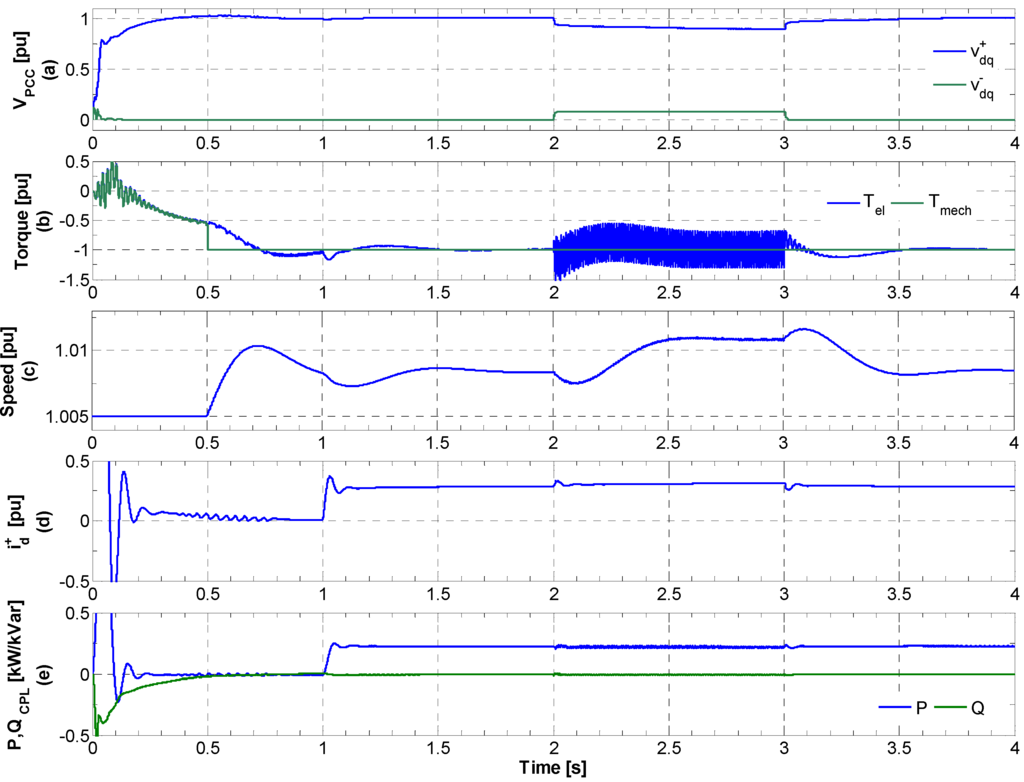
Figure 8.
Simulation results for asymmetrical grid fault without CPL voltage control. (a) Positive and negative sequence voltages at PCC; (b) IG Torque; (c) IG speed; (d) Active component of current representing the load power; (e) CPL active and reactive powers.
Figure 8.
Simulation results for asymmetrical grid fault without CPL voltage control. (a) Positive and negative sequence voltages at PCC; (b) IG Torque; (c) IG speed; (d) Active component of current representing the load power; (e) CPL active and reactive powers.

The results for only the positive sequence voltage control by CPL under the same fault condition have been presented in Figure 9. The CPL is able to compensate the positive sequence voltage at PCC by injecting the component of positive sequence reactive current iq+ (see Figure 9d). CPL also consumes positive sequence active current component representing the load power. Due to the positive sequence voltage compensation, the speed of the rotor does not increase, confirming a stable operating point for the system. The torque ripples in the IG still remain due to the presence of negative sequence voltage in the system.
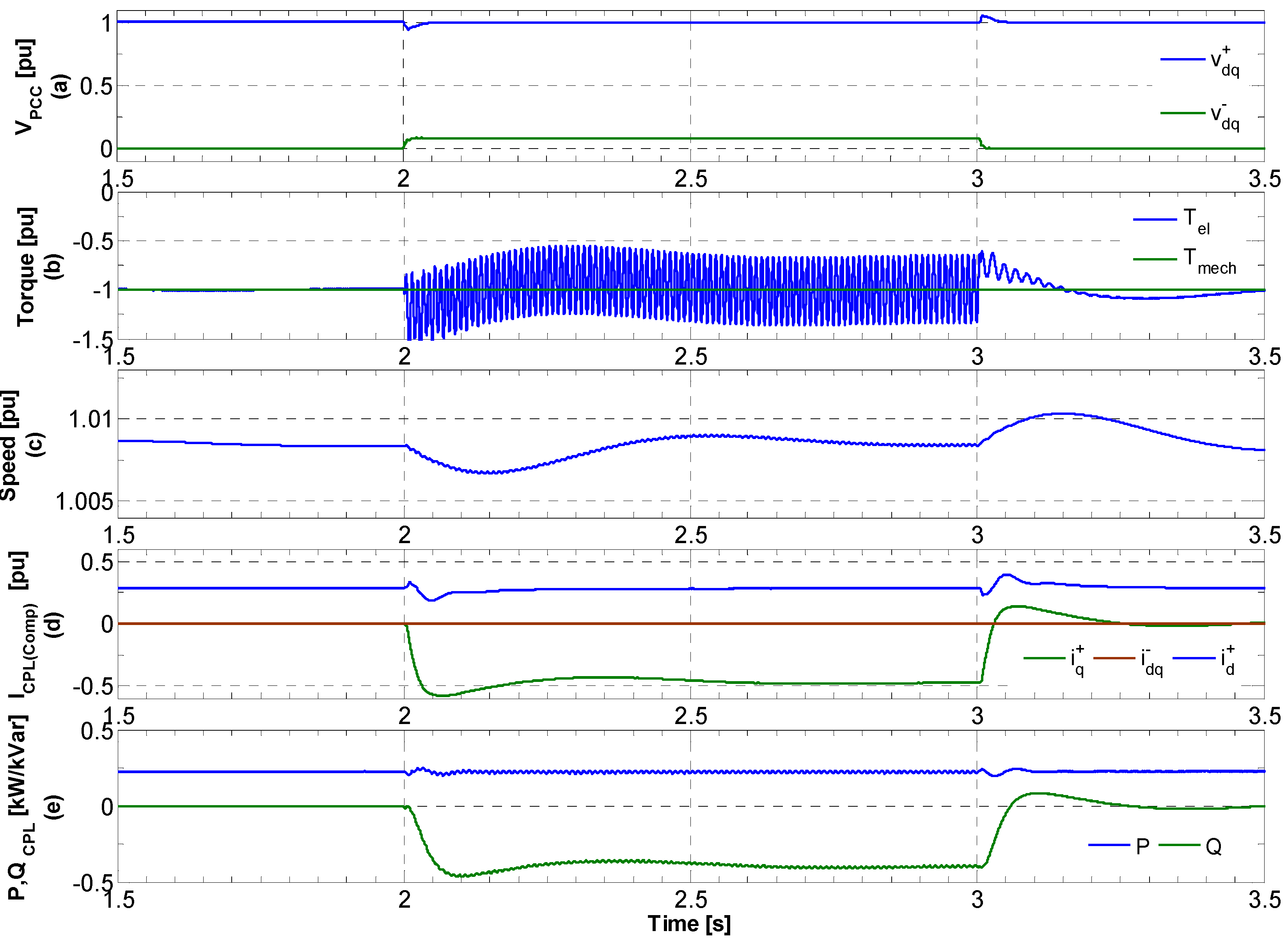
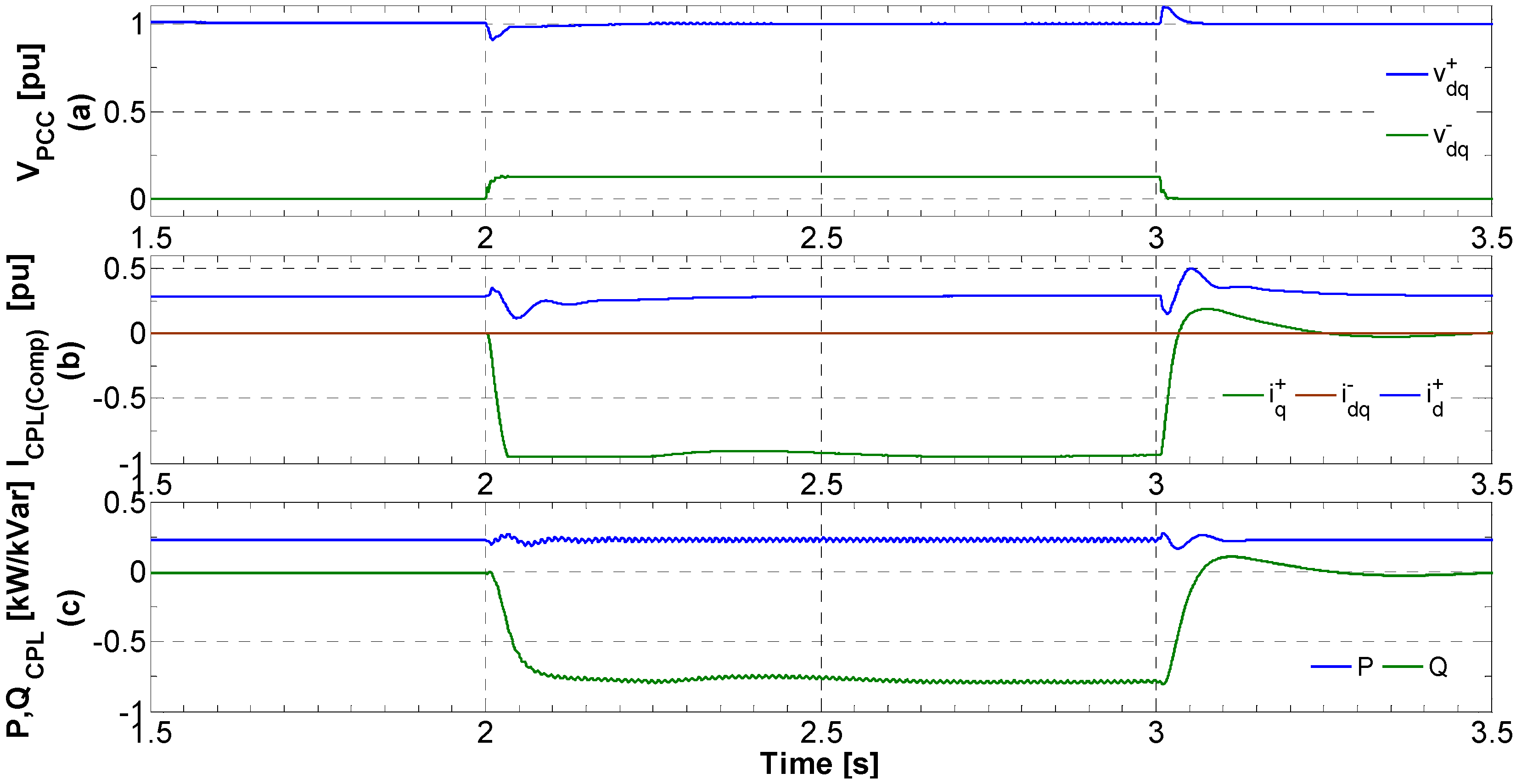
Figure 10 illustrates the results when CPL is controlled to compensate the negative sequence voltage only. The CPL control strategy completely eliminates the negative sequence component of the PCC voltage as shown in Figure 10a. CPL injects the negative sequence component of active and reactive current idq− for this purpose (see Figure 10d). This result in the removal of heavy torque ripples during the fault (see Figure 10b). As the positive sequence component of the voltage is not compensated, therefore, the rotor keeps on accelerating and IG consumes more reactive power, resulting in a continuous decrease in the positive sequence voltage component. The system, however, does not reach the mechanical unstable point and returns to the rated operating point after the fault. Figure 10e shows the oscillating CPL active and reactive power during the fault. The active power oscillates around the constant power consumed by the load. This is the drawback of the CPL control strategy; however, it is unavoidable as the active component of the negative sequence current id−, representing this oscillating power, is necessary to eliminate the quadrature component of the negative sequence voltage vq− (see Figure 3). The same reason holds for the oscillation in the CPL reactive power during the fault, as the presence of reactive component of the negative sequence current iq− is essential in order to compensate the direct component of negative sequence voltage vd−.

Figure 9.
Simulation results with CPL positive sequence voltage control. (a) Positive and negative sequence voltages at PCC; (b) IG Torque; (c) IG speed; (d) Positive and negative component of compensating current; (e) CPL active and reactive powers.
Figure 9.
Simulation results with CPL positive sequence voltage control. (a) Positive and negative sequence voltages at PCC; (b) IG Torque; (c) IG speed; (d) Positive and negative component of compensating current; (e) CPL active and reactive powers.
5.1. Coordinated Control of Positive and Negative Sequence Voltage Components
The compensation of positive and negative sequence voltage can only be achieved when the CPL has unused current capacity (remaining current after fulfilling the load active power requirements). The coordination between the positive and negative sequence voltage compensation is dependent on the severity of the grid fault. For smaller unbalanced voltage sag, CPL may be able to achieve the independent compensation of both the positive and negative sequence of PCC voltage. The current limiter block shown in Figure 3 ensures that the total current capability of the CPL must not be exceeded. The total CPL current rating ICPL,N can be represented by Equation (14):
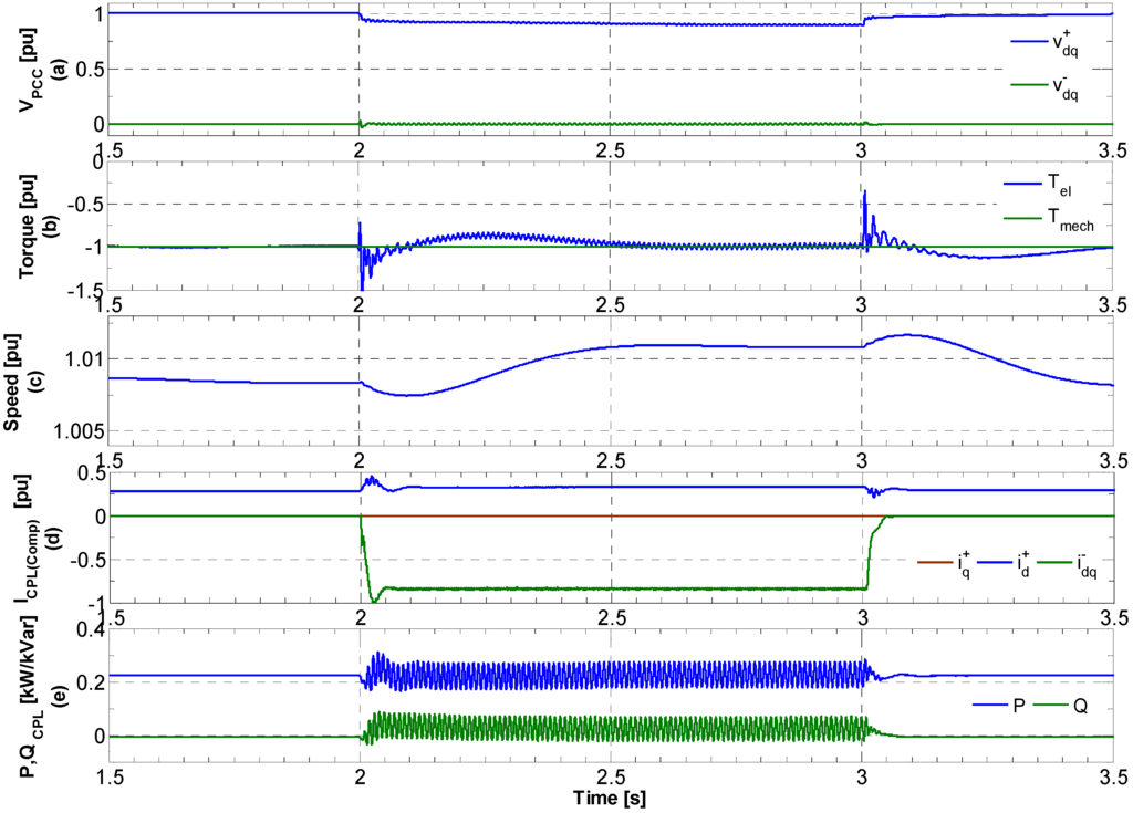
Figure 10.
Simulation results with CPL negative sequence voltage control. (a) Positive and negative sequence voltages at PCC; (b) IG Torque; (c) IG speed; (d) Positive and negative component of compensating current; (e) CPL active and reactive powers.
Figure 10.
Simulation results with CPL negative sequence voltage control. (a) Positive and negative sequence voltages at PCC; (b) IG Torque; (c) IG speed; (d) Positive and negative component of compensating current; (e) CPL active and reactive powers.

Figure 11 shows the simulation results for the same fault severity when CPL control strategy allows the compensation of both the positive and negative sequence voltage components independently. In this case, CPL injects both the positive and negative sequence of the current for compensation purpose without exceeding its nominal current. It can be observed that coordinated voltage control results in the elimination of torque ripples and the acceleration of the rotor during the fault is also avoided (see Figures 11b,c). This is an ideal situation where an already installed resource is able to provide the ancillary service that was earlier supposed to be achieved with a dedicated STATCOM or DFIG wind turbine.
For higher voltage sag, the CPL may not have the sufficient current capacity left to achieve the coordinated voltage control. In this case, the priority is given to positive sequence voltage compensation; because the speed of the rotor keeps on increasing out of control and a voltage collapse becomes unavoidable. Figure 12 shows the results for a more severe fault (single phase amplitude drops to 58%). The CPL is able to compensate the positive sequence voltage by injecting its full allowed current capacity. If the fault is even more severe, then the CPL will not be able to fully compensate the positive sequence voltage. However, in that case, it can avoid the voltage collapse by supporting the PCC voltage by injecting maximum current without exceeding its current rating. The disadvantage in this case is that there is no extra current to compensate the negative sequence voltage and the torque oscillations will remain during the fault, resulting in unbalanced heating in the stator windings.

Figure 11.
Simulation results with CPL coordinated positive and negative sequence voltage control. (a) Positive and negative sequence voltages at PCC; (b) IG Torque; (c) IG speed; (d) Compensating current; (e) CPL active and reactive powers.
Figure 11.
Simulation results with CPL coordinated positive and negative sequence voltage control. (a) Positive and negative sequence voltages at PCC; (b) IG Torque; (c) IG speed; (d) Compensating current; (e) CPL active and reactive powers.
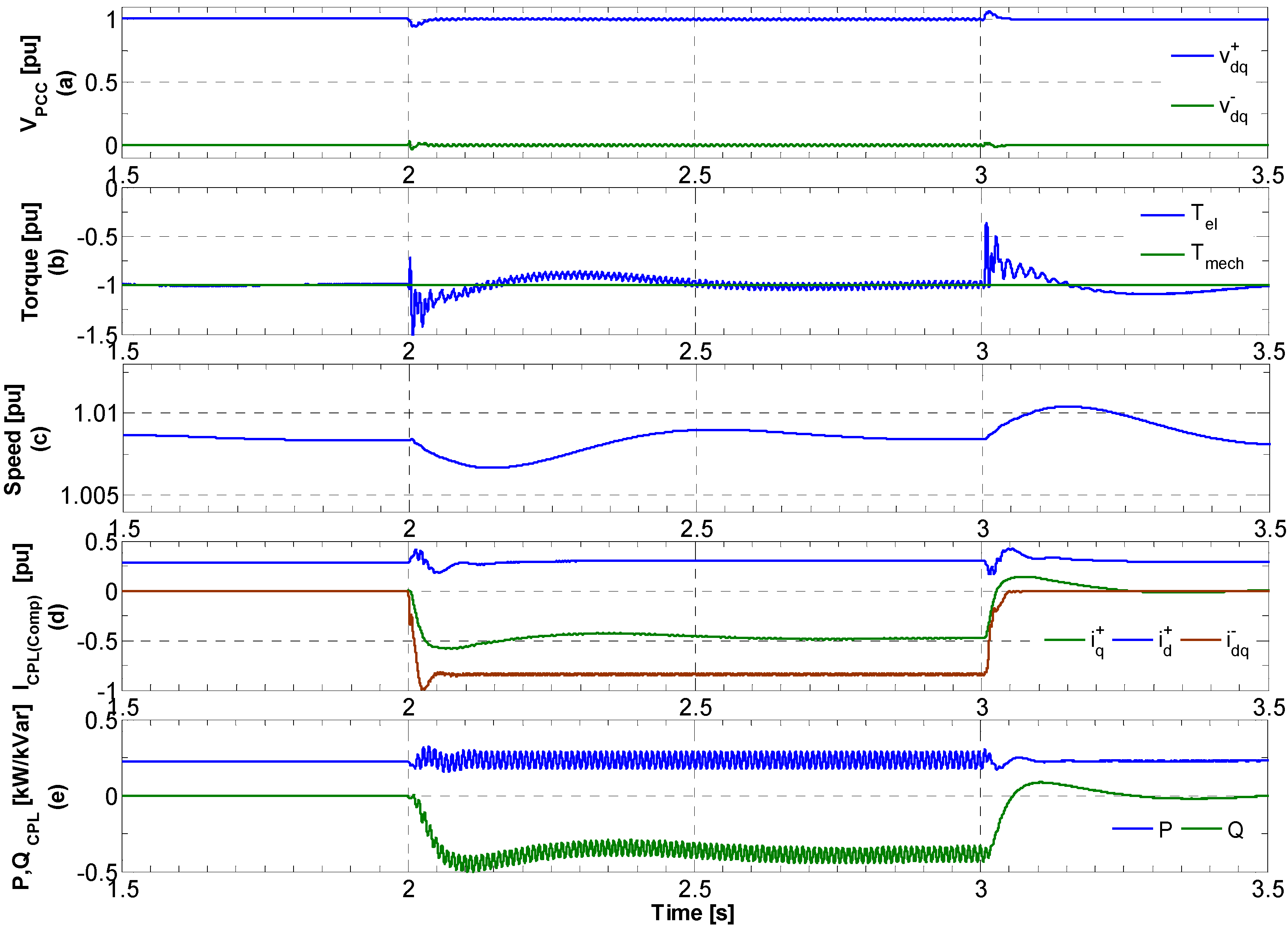
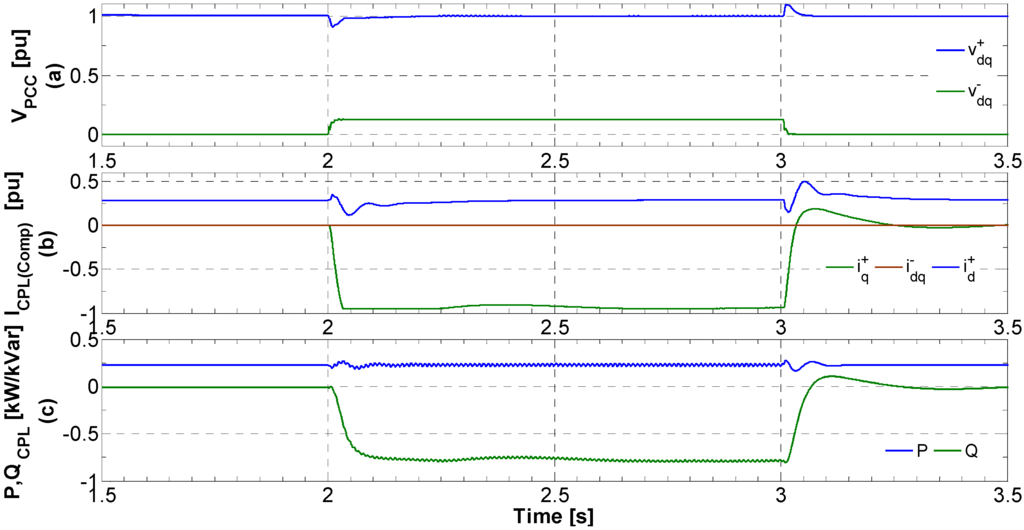
Figure 12.
Simulation results for higher voltage sag with CPL coordinated positive and negative sequence voltage control. (a) Positive and negative sequence voltages at PCC; (b) Compensating current; (c) CPL active and reactive powers.
Figure 12.
Simulation results for higher voltage sag with CPL coordinated positive and negative sequence voltage control. (a) Positive and negative sequence voltages at PCC; (b) Compensating current; (c) CPL active and reactive powers.
Simulation results enhance the understanding of the operation of IG-based wind turbine when CPL is controlled to provide the positive and negative sequence voltage compensation independently. The positive sequence voltage compensation enhance the torque capability of the IG and avoids the acceleration of the rotor, while the negative sequence voltage compensation helps increasing the lifetime of the generator drive train by removing the torque ripples. However, voltage compensation capability is totally dependent on the chosen current rating of the CPL. It can only provide the compensating current if there is some current left after fully providing the load power needs. The overall impedance of the power system also plays an important role. The voltage compensation capability of the CPL is high for a weak power grid.
5.2. Simulation Results with Multi-Machine Wind Farm
In this section, a simulation analysis is performed for a medium size wind farm to confirm the validity of the proposed FRT enhancement method discussed in the previous section. The single machine system of Figure 6 is replaced with multi-machine system and a 2.225 MW IG-based wind farm connected directly to the medium voltage grid is considered. An aggregate model of the wind farm is used so that the sum of the turbines is modeled as one generator using the standard T-equivalent circuit. The rating of the each IG is the same as considered in the previous section and presented in Table 1. The fault resistance for the asymmetrical grid fault is kept the same as in the previous sections and the single phase amplitude falls to 78%.
Figure 13 presents the simulation results for the case when CPL voltage control is disabled. The overall inductance of the system is increased due to the introduction of many IGs and it is clear from Figure 13a that the magnitude of the positive sequence voltage drops to a lower value and the component of the negative sequence voltage is not higher compared to the single machine system. The smaller negative sequence component results in comparatively lower torque oscillations. The rotor speed increases during the fault. In this case, the system does not reach the mechanically unstable point and the system slowly regains the pre-fault operating conditions. CPL consumes 225 kW power at time t = 1 s. An increase in positive sequence active current component can be observed during the fault when the voltage decreases as shown in Figure 13d.
Simulation results for the case when CPL is controlled to provide both the positive and negative sequence voltage compensation are presented in Figure 14. CPL control affectively maintains the voltage during the fault to the specified values. The torque ripples are largely reduced after the negative sequence voltage compensation. The positive sequence voltage avoids the acceleration of the rotor during the fault and helps to improve the overall system stability and the possible disconnection of the wind farm. CPL injects the positive and negative sequence compensating currents and the current limiter block shown in Figure 3 does not impose any restrictions on the amount of injected current. Figure 14d illustrates the different CPL current components. The total CPL current in this case is 1.44 pu. This is 44% increase in the total CPL current rating even though the system’s power rating is increased by three-fold. However, as the overall inductance of the system is very high in this case, the CPL does not need to inject three times more compensating current.
The obvious advantage of the proposed scheme is that the installed resources at the distribution level can be used to achieve the performance of a STATCOM that is specifically used for compensation purpose. However, in order to achieve this, the CPL current rating must either be enhanced or it must be operated below its rated active power to allow the injection of extra current for voltage compensation.
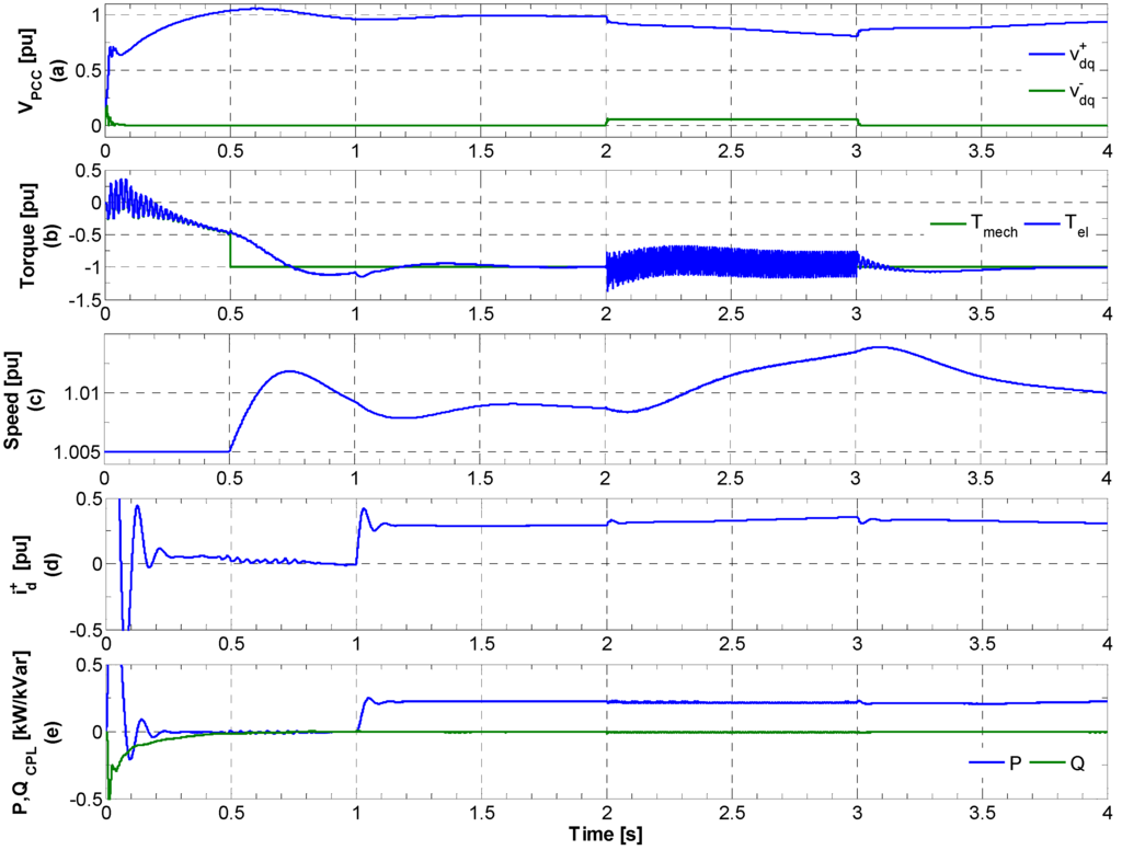
Figure 13.
Simulation results for multi-machine medium size wind farm without CPL voltage control. (a) Positive and negative sequence voltages at PCC; (b) IG Torque; (c) IG Speed; (d) Active component of current representing the load power; (e) CPL active and reactive powers.
Figure 13.
Simulation results for multi-machine medium size wind farm without CPL voltage control. (a) Positive and negative sequence voltages at PCC; (b) IG Torque; (c) IG Speed; (d) Active component of current representing the load power; (e) CPL active and reactive powers.
6. Conclusions
This paper explores the possibility of using a CPL to mitigate the asymmetrical grid faults in an IG- based wind turbine instead of using dedicated devices such as a STATCOM or DFIG wind turbine. A detailed simulation analysis is carried out to understand the voltage control performed by CPL and the resulting operation of the IG under unbalanced fault. A tightly regulated VSC utilizing vector control method is used as a CPL. A DSOGI-PLL is employed in the control strategy for the precise extraction of positive and negative sequence components of the PCC voltage. A CPL control structure is proposed to achieve the independent compensation of positive and negative sequence of the voltage. The priority has been assigned to the positive sequence voltage control for the maximum FRT enhancement of the wind turbine. The positive sequence voltage compensation avoids the acceleration of the rotor and improves the voltage stability. The negative sequence voltage control is activated when there is remaining current capacity to remove the torque oscillation in the machine during the unbalanced fault. The simulation results for multi-machine wind farm confirm that the CPL effectively provides the positive and negative sequence voltage compensation and the increase in CPL compensation currents is not in proportion with the increase in system power rating.
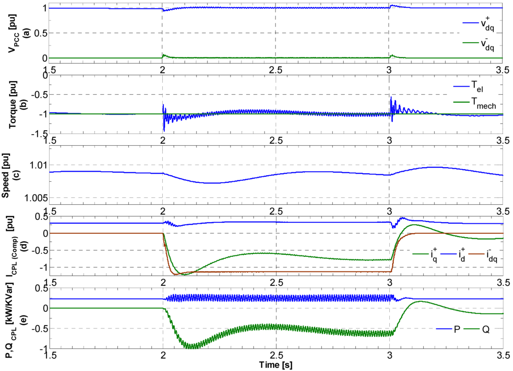
Figure 14.
Simulation results for multi-machine medium size wind farm with CPL voltage control. (a) Positive and negative sequence voltages at PCC; (b) IG Torque; (c) IG Speed; (d) Compensating current; (e) CPL active and reactive powers.
Figure 14.
Simulation results for multi-machine medium size wind farm with CPL voltage control. (a) Positive and negative sequence voltages at PCC; (b) IG Torque; (c) IG Speed; (d) Compensating current; (e) CPL active and reactive powers.

7. Future Work
The simplified system presented in this paper for understanding the utilization of CPL for unbalanced fault mitigation could be further extended into the analysis of more complex power system with several dispersed CPLs. An analytical study on the optimal placement of the distributed CPLs in the distribution system could be performed. An analytical and simulation based investigation of the overall system stability could be done in relation to the critical share of CPLs at the distribution level for unbalanced voltage sags. A performance comparison could be made between the distributed CPLs and centralized STATCOM and their current rating could also be evaluated for different severity of asymmetrical grid faults.
References
- Atwa, Y.M.; El-Saadany, E.F. Optimal allocation of ESS in distribution systems with a high penetration of wind energy. IEEE Trans. Power Syst. 2010, 4, 1815–1822. [Google Scholar] [CrossRef]
- Hossain, M.J.; Pota, H.R.; Ugrinovskii, V.; Ramos, R.A. Robust STATCOM Control for the Enhancement of Fault Ride-through Capability of Fixed Speed Wind Generators. In Proceedings of IEEE Control Applications (CCA) & Intelligent Control (ISIC), St. Petersburg, Russia, 8–10 July 2009; pp. 1505–1510.
- Lu, M.-S.; Chang, C.-L.; Lee, W.-J.; Wang, L. Combining the wind power generation system with energy storage equipment. IEEE Trans. Ind. Appl. 2009, 6, 2109–2115. [Google Scholar]
- Large Scale Integration of Wind Energy in the European Power Supply: Analysis, Issues and Recommendations; Technical Report for European Wind Energy Association (EWEA): Brussels, Belgium, December 2005.
- Erlich, I.; Winter, W.; Dittrich, A. Advanced Grid Requirements for the Integration of Wind Turbines into the German Transmission System. In Proceedings of IEEE Power Engineering Society General Meeting, Montreal, Canada; 2006; p. 7. [Google Scholar]
- Rodriguez, P.; Luna, A.; Medeiros, G.; Tedorescu, R.; Blaabjerg, F. Control of STATCOM in Wind Power Plants Based on Induction Generators during Asymmetrical Grid Faults. In Proceedings of the 2010 International Power Electronics Conference (IPEC), Sapporo, Japan, 21–24 June 2010; pp. 2066–2073.
- Bary, D. Increasing Renewable Energies Accessibility in Ireland. Proceedings of 9th World Energy Congress. 2004, pp. 1–10. Available online: http://www.worldenergy.org/documents/congresspapers/barryd0904ys.pdf (accessed on 11 March 2013).
- Emadi, A. Modeling of Power Electronics Loads in AC Distribution Systems Using the Generalized State-Space Averaging Method. IEEE Trans. Ind. Electron. 2004, 5, 992–1000. [Google Scholar] [CrossRef]
- Emadi, A.; Khaligh, A.; Rivetta, C.H.; Williamson, G.A. Constant power loads and negative impedance instability in automotive systems: Definition, modeling, stability, and control of power electronic converters and motor drives. IEEE Trans. Veh. Technol. 2006, 55, 1112–1125. [Google Scholar] [CrossRef]
- Khaligh, A.; Rahimi, A.M.; Emadi, A. Modified pulse-adjustment technique to control dc/dc converters driving variable constant-power loads. IEEE Trans. Ind. Electron. 2008, 3, 1133–1146. [Google Scholar] [CrossRef]
- Heskes, P.J.M.; Myrzik, J.M.A.; Kling, W.L. Power Electronic Loads with Negative Differential Impedance in a Low Voltage Distribution System. In Proceedings of 20th International Conference on Electricity Distribution, Prague, Czech Republic, 8–11 June 2009.
- Molinas, M.; Kondoh, J. Power Electronic Loads as Providers of Reactive Power Ancillary Service to the Grid: Analytical and Experimental Study. In Proceedings of 13th European Conference on Power Electronics and Applications, 2009 (EPE'09). Barcelona, Spain, 8–10 September 2009; pp. 1–10.
- Jelani, N.; Molinas, M. Stability Investigation of Control System for Power Electronic Converter Acting as Load Interface in AC Distribution System. In Proceedings of IEEE International Symposium on Industrial Electronics (ISIE), Gdansk, Poland, 27–30 June 2011; pp. 408–413.
- Jelani, N.; Molinas, M. Optimal Use of Power Electronic Interfaces for Loads in Distributed Systems. In Proceedings of 2010 IEEE International Symposium on Industrial Electronics (ISIE), Bari, Italy, 4–7 July 2010; pp. 2449–2454.
- Wang, Y.; Xu, L.; Williams, B.W. Compensation of network voltage unbalance using doubly fed induction generator-based wind farms. IET Renew. Power Gener. 2009, 1, 12–22. [Google Scholar] [CrossRef]
- Singh, B.; Murthy, S.S.; Gupta, S. STATCOM-based voltage regulator for self-excited induction generator feeding nonlinear loads. IEEE Trans. Ind. Electron. 2006, 5, 1437–1452. [Google Scholar] [CrossRef]
- Azevedo, G.M.S.; Rodriguez, P.; Cavalcanti, M.C.; Vazquez, G.; Neves, F.A.S. New Control Strategy to Allow the Photovoltaic Systems Operation under Grid Faults. In Proceedings of 2009 Power Electronics Conference, Bonito, Brazil, 27 September–1 October 2009; pp. 196–201.
- Jusoh, A.B. The Instability Effect of Constant Power Loads. In Proceedings of National Power and Energy Conference, Kuala Lumpur, Malaysia, 29–30 November 2004; pp. 175–179.
- Rodriguez, P.; Luna, A.; Ciobotaru, M.; Teodorescu, R.; Blaabjerg, F. Advanced Grid Synchronization System for Power Converters under Unbalanced and Distorted Operating Conditions. In Proceedings of the 32nd Annual Conference on IEEE Industrial Electronics (IECON 2006), Paris, France, 6–10 November 2006; pp. 5173–5178.
- Rodriguez, P.; Teodorescu, R.; Candela, I.; Timbus, A.V.; Liserre, M.; Blaabjerg, F. New Positive-sequence Voltage Detector for Grid Synchronization of Power Converters under Faulty Grid Conditions. In Proceedings of the 37th IEEE Power Electronics Specialists Conference (PESC’06), Jeju, South Korea, 18–22 June 2006; pp. 1–7.
- Ciobotaru, M.; Teodorescu, R.; Blaabjerg, F. A New Single-Phase PLL Structure Based on Second Order Generalized Integrator. In Proceedings of 37th IEEE Power Electronics Specialists Conference, Jeju, South Korea, 18–22 June 2006; pp. 1–6.
- Lyon, W.V. Application of the Method of Symmetrical Components; McGraw-Hill: New York, NY, USA, 1937. [Google Scholar]
- Noureldeen, O. Low voltage ride through strategies for SCIG wind turbines interconnected grid. Int. J. Electr. Comput. Sci. 2011, 11, 59–64. [Google Scholar]
- Anaya-Lara, O.; Jenkins, N.; Ekanayake, J.; Cartwright, P.; Hughes, M. Wind Energy Generation: Modelling and Control; John Wiley and Sons: Hoboken, NJ, USA, 2009. [Google Scholar]
- Tenti, P.; Costabeber, A.; Mattavelli, P.; Trombetti, D. Distribution loss minimization by token ring control of power electronic interfaces in residential micro-grids. IEEE Trans. Ind. Electron. 2012, 59, 3817–3826. [Google Scholar] [CrossRef]
© 2013 by the authors; licensee MDPI, Basel, Switzerland. This article is an open access article distributed under the terms and conditions of the Creative Commons Attribution license (http://creativecommons.org/licenses/by/3.0/).