Abstract
A self-supported direct borohydride-hydrogen peroxide fuel cell system with internal manifolds and an auxiliary control unit is reported. The system, while operating under ambient conditions, delivers a peak power of 40 W with about 2 W to run the auxiliary control unit. A critical cause and effect analysis, on the data for single cells and stack, suggests the optimum concentrations of fuel and oxidant to be 8 wt. % NaBH4 and 2 M H2O2, respectively in extending the operating time of the system. Such a fuel cell system is ideally suited for submersible and aerospace applications where anaerobic conditions prevail.
Introduction
Polymer electrolyte fuel cells (PEFCs) employ hydrogen as fuel. But hydrogen is not available freely in Nature and hence needs to be generated. At present, hydrogen is industrially generated by steam reforming of natural gas [1]. But the hydrogen generated by such a process contains carbon monoxide, which even at miniscule levels can poison the platinum catalyst affecting the performance of the PEFCs. Besides, gaseous hydrogen needs to be stored and transported to the sites where the PEFCs are located [1,2,3].
Owing to the aforesaid limitations, certain hydrogen-carrying organic fuels, such as methanol, ethanol, propanol, ethylene glycol and diethyl ether have been considered for fuelling PEFCs directly. Among these, methanol, with a hydrogen content of 12.8 wt. %, is the most attractive liquid fuel [4], but PEFCs fuelled directly with methanol suffer from methanol crossover from anode to cathode across the polymer-membrane electrolyte that affects the cell performance. Besides, such fuel cells have the inherent limitations of low open-circuit-potential and low electrochemical-activity [5].
The use of sodium borohydride as a fuel in a direct borohydride fuel cell (DBFC) seems promising as these cells exhibit a higher open-circuit voltage and, consequently, a higher power density in relation to direct alcohol fuel cells [6]. However, there are several technical challenges that need to be addressed in the DBFCs employing air or H2O2 as oxidant [7,8]. Among these, DBFCs with acidified H2O2 as oxidant provide high operating voltages and power densities, and are especially useful for submersible and space applications where anaerobic conditions prevail [8,9,10,11].
In this communication, we report a self-supported 40W alkaline NaBH4/acidic H2O2 DBFC system with internal manifolds and an auxiliary control unit. The operational features of the DBFC have been examined employing diagnostic methods with respect to the amounts of oxidant, alkali and acid required for every gram of fuel electro-oxidized. In the literature [6,7,12] several optimization studies with varying concentrations of fuel and oxidant for the DBFCs have been reported with the objective to attain the maximum power density. In the present study, an attempt is made to achieve the optimum fuel and oxidant concentrations to attain maximum operation time.
2. Results and Discussion
2.1. The operating principle of DBFCs
At the anode of the DBFC the following reactions take place:
8 NaOH → 8 Na+ + 8 OH-
NaBH4 + 8 OH- → NaBO2 + 6 H2O + 8 e–
Sodium borohydride could concomitantly hydrolyse as:
NaBH4 + 2 H2O ↔ 4 H2↑ + NaBO2
Hydrogen thus generated may electrochemically oxidise at the anode as:
or it could be released to the atmosphere.
4 H2 → 8 H+ + 8 e-
At the cathode of the DBFC, the following reactions can take place:
(a) Chemical decomposition of H2O2 occurs as follows:
4 H2O2 → 4 H2O + 2 O2↑
Oxygen gas thus generated can be reduced to water as:
or it could be released to the atmosphere.
2 O2 + 8 H+ + 8 e- → 4 H2O
(b) Electrochemical reduction of H2O2 takes place as:
Na+-ions pass through the membrane electrolyte and combine with the SO42- ions to produce Na2SO4 as follows:
4 H2O2 + 8 H+ + 8 e- → 8 H2O
8 Na+ + 4 SO42- → 4 Na2SO4
Accordingly, the net cell reaction can be written as:
The operating principle of the DBFC is depicted schematically in Figure 1.
NaBH4 + 8 NaOH + 4 H2O2 + 4 H2SO4 → NaBO2 + 14 H2O + 4 Na2SO4
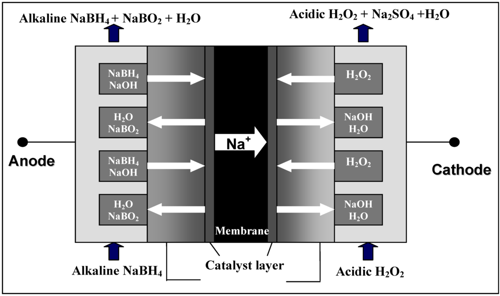
Figure 1.
Operating principle of the DBFC.
2.2. Single cell studies
As there are many possible sets of reactions that could take place concomitant with reactant crossover, it is hard to calculate the amount of reactants required using stoichiometric equations. Accordingly, studies were conducted to determine the amounts of fuel, oxidant and products in the initial and spent solutions. These studies were performed on a single cell with an active area of 45 cm2 and the results are summarized in Table 1.

Table 1.
stoichiometrically calculated and experimentally obtained values of reactants for given amount of fuel.
| Reactant | NaBH4 | NaOH | H2O2 | H2SO4 | Total |
|---|---|---|---|---|---|
| Stoichometric (g) | x | 8.46x | 3.6x | 10.37x | 23.43 x |
| Experimental (g) | x | 9.47x | 4x | 11.61x | 26.08x + H2O weight |
The stoichiometric amounts of all the reactants are calculated according to reaction (9). For every gram of NaBH4 electro-oxidized, 8.46 g of NaOH, 3.6 g of H2O2 and 10.37 g of H2SO4 are required stoichiometrically for the operation of the DBFC.
The amount of NaBH4 electro-oxidized is determined by the charge (in coulombs) generated during the experiment. For example, if the total amount of NaBH4 present in the anolyte is 1g and 30% of it is electro-oxidized and 50% hydrolyzed with 20% remaining unreacted, then the amount (x) of NaBH4 that is electro-oxidized is equal to 0.3 g. The amount of NaOH consumed due to reaction and crossover from anloyte to catholyte is determined gravimetrically, albeit indirectly, by estimating the amount of SO42- in the spent catholyte. From reaction (8), the amount of NaOH (in g) is estimated. Since some amount of NaOH crosses over from anolyte to catholyte, the quantity of NaOH required is always higher than its stoichiometric estimate. The amount of H2O2 is determined by permanganometry by titrating the initial and spent solutions against KMnO4. The amount 4x in Table 1 includes the amount (in g) of H2O2 electro-oxidized (3.6x) and decomposed (0.4x) into water and oxygen. The amount of H2SO4 consumed is determined by titrating the initial and spent catholytes against NaOH. From these data, it is seen that to generate a capacity of 5.67 Ah (1g equivalent of NaBH4), a minimum of 25.08 g of H2O2 and supporting reactant needs to be supplied to the system, excluding water.
In order to increase the energy density of the DBFC system, it is mandatory to reduce the weight of anolyte and catholyte to as low a value as possible. To this end, concentrations of fuel and oxidant in the anolyte and catholyte, respectively, were kept high enough to store optimum amounts of the fuel and oxidant. The optimum values for the fuel and oxidant are obtained as described in Sections 3.2.1 and 3.2.2, respectively.
2.2.1. Optimization of oxidant concentration
Keeping the fuel (NaBH4) concentration constant, the concentration of the oxidant (H2O2) is optimized. As received commercial 30 % H2O2 (~ 8 M) is used as the initial concentration for the optimization studies. Fuel concentration is kept at 8 wt. % NaBH4 in 11 wt. % NaOH while oxidant concentration is varied between 8 M and 6 M H2O2 in 1.5 M H2SO4. Figure 2 shows the polarization data for DBFC operated with 6 M and 8 M H2O2 while keeping the fuel concentration at 8 wt. % NaBH4 in 11 wt. % NaOH. It is found that the performance for the DBFC with 6 M H2O2 is superior in relation to performance of the DBFC employing 8 M H2O2. This could be due to the increased decomposition of H2O2 at higher concentrations as well coverage of the electrode surface by oxygen formed due to the decomposition of H2O2 [13]. For galvanostatic operation of the DBFC, 50 mL of 8 M and 6 M H2O2 solutions are fed to the cell. Figure 3 shows the galvanostatic data for the cell employing 8 M H2O2 and 6 M H2O2. From the data, it is seen that the operating time for the DBFC employing 8 M H2O2 is longer because of the availability of higher amount of H2O2 for the reaction. Accordingly, 8 M H2O2 in 1.5 M H2SO4 is found to be optimum.
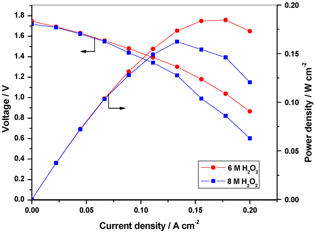
Figure 2.
Polarization data for the DBFC with 6 M and 8 M H2O2 in aqueous 1.5 M H2SO4 as catholyte and 8 wt. % NaBH4 as anolyte.
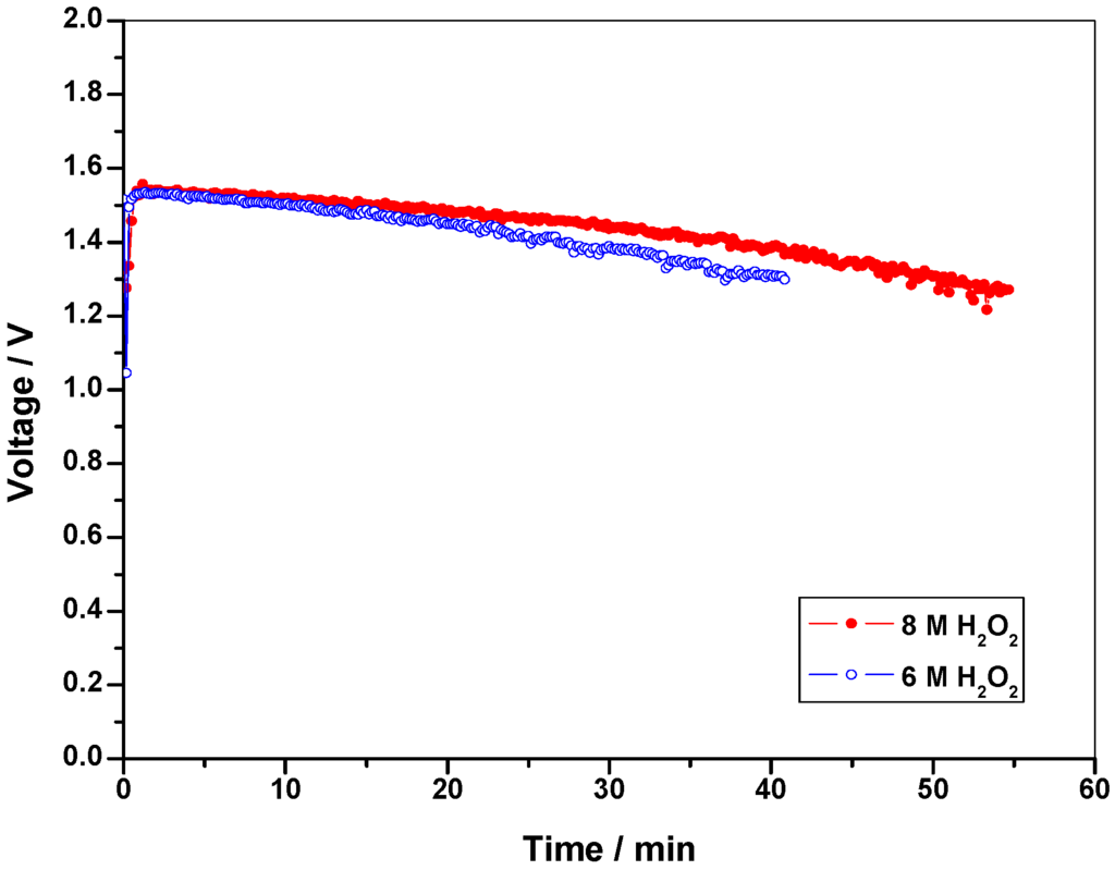
Figure 3.
Performance data for the DBFC with 6 M and 8 M H2O2 in aqueous 1.5 M H2SO4 as catholyte and 8 wt. % NaBH4 as anolyte at a load current-density of 65 mA cm-2.
2.2.2. Optimization of fuel concentration
Since concentrations higher than 30 wt. % NaBH4 in 11 wt. % NaOH is too viscous to be handled by a pump, optimization studies have been conducted using this concentration as the initial concentration. Keeping the oxidant concentration at 8 M H2O2 in 1.5 M H2SO4, cell polarization data are obtained for 30 wt. % , 15 wt. %, 8 wt. % and 4 wt. % NaBH4 in 11 wt. % NaOH as shown in Figure 4. It is found that the performance for the DBFC with 4 wt. % NaBH4 is superior to the performance for the DBFCs employing 30 wt. %, 15 wt. % and 8 wt. % NaBH4. For the galvanostatic study, 40 mL of NaBH4 solution and 50 mL of optimized concentration of 8 M H2O2 solution are fed to the cell and the data in Figure 5 show that solution containing 8 wt. % NaBH4 sustains longer operating-time owing to the availability of higher amounts of NaBH4 for the reaction. Accordingly, 8 wt. % NaBH4 solutions are considered to be optimum. Based on these data, percentage values of fuel and oxidant utilized in the single cell are found to be 15% and 12.5%, respectively.
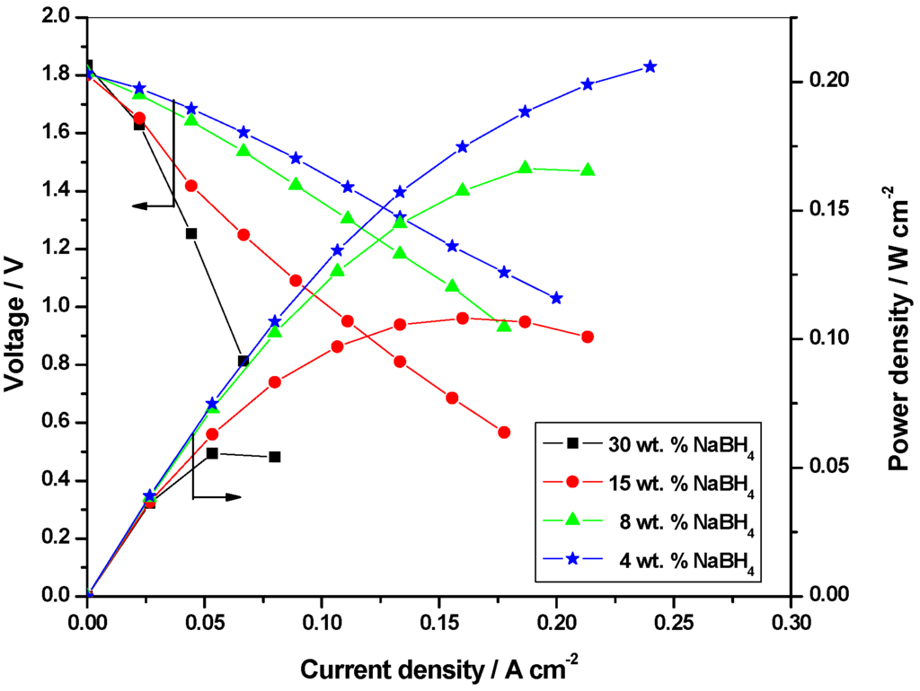
Figure 4.
Polarization data for the DBFC with 4 wt. %, 8 wt. %, 15 wt. % and 30 wt. % NaBH4 as anolyte and 8 M H2O2 as catholyte.
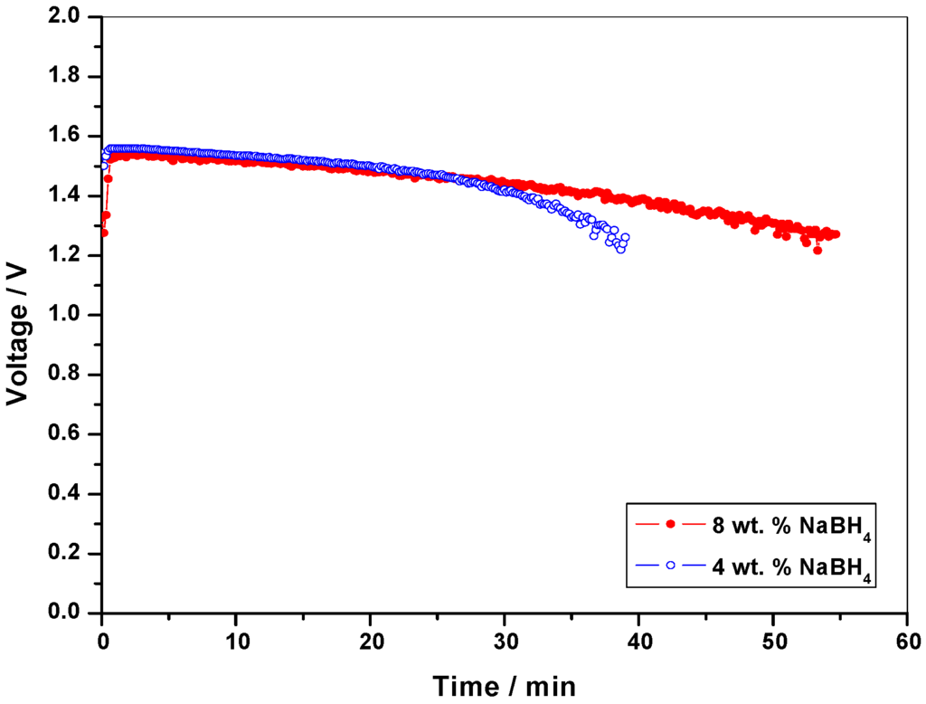
Figure 5.
Performance data for the DBFC with 4 wt. % and 8 wt. % anolyte and 8 M H2O2 as the catholyte at a load current-density of 65 mA cm-2.
2.3. Studies on the DBFC stack
2.3.1. Optimization of oxidant concentration
Keeping the fuel concentration constant at 8 wt. %, cell polarization data have been obtained for 8, 6, 4 and 2 M H2O2 in 1.5 M H2SO4. For galvanostatic studies, 200 ml of 8 wt. % NaBH4 solution and 250 mL of 8 M H2O2 solution are fed to the stack. Unlike the single cell, the performance of the stack happens to be different while varying oxidant concentration as seen from the data in Table 2. The operation time increases as the concentration of H2O2 is decreased from 8 M to 2 M; this behavior can be attributed to rise in operating temperature of the stack as compared to the single cell. During the operation of the stack, H2O2 decomposition at cathode occurs as an exothermic (23.44 kcal/mole) reaction. It is noteworthy that an increase of 10oC can enhance the decomposition rate of H2O2 by a factor of 2.3 which is typical of a first-order rate reaction [14]. As the concentration of H2O2 in solution increases, less water becomes available to absorb the heat of decomposition. Above 2 M H2O2, decomposition of H2O2 limits the operation time whereas the operation time for 1 M H2O2 is limited because it contains less amount of H2O2 than the amount required stoichoimetrically while considering 14 % of fuel to be electro-oxidised. Accordingly, 2 M H2O2 is found to be optimum.
Table 2.
Oxidant concentration optimization data for five-cell DBFC stack with 8 wt. % NaBH4 and 11 wt. % NaOH.
| H2O2 (M) in 1.5 M H2SO4 | 8 | 6 | 4 | 2 | 1 |
| Operating time (min.) | 37 | 41 | 47 | 52 | 36 |
2.3.2. Optimization of fuel concentration
Akin to single cell studies, the operating time for the DBFC stack using 4 wt. % NaBH4 is less than DBFC stack using 8 wt. % NaBH4 because of the availability of higher amounts of NaBH4 for the reaction as seen from the data in Table 3. Accordingly, 8 wt. % NaBH4 is taken to be optimum. In the present study, percentage of fuel and oxidant utilized by stack are found to be 14% and 47%, respectively.
Table 3.
Fuel concentration optimization data for five-cell DBFC stack with optimized 8 M H2O2 in 1.5 M H2SO4 in aqueous media.
| NaBH4 (wt. %) in 11 wt. % NaOH | 30 | 15 | 8 | 4 |
| Operating time (min) | - | - | 52 | 40 |
2.3.3. Stack polarization
A maximum of 40 W is generated from this stack at a peak power-density of 180 mW cm-2 at 5V as shown in Figure 6.
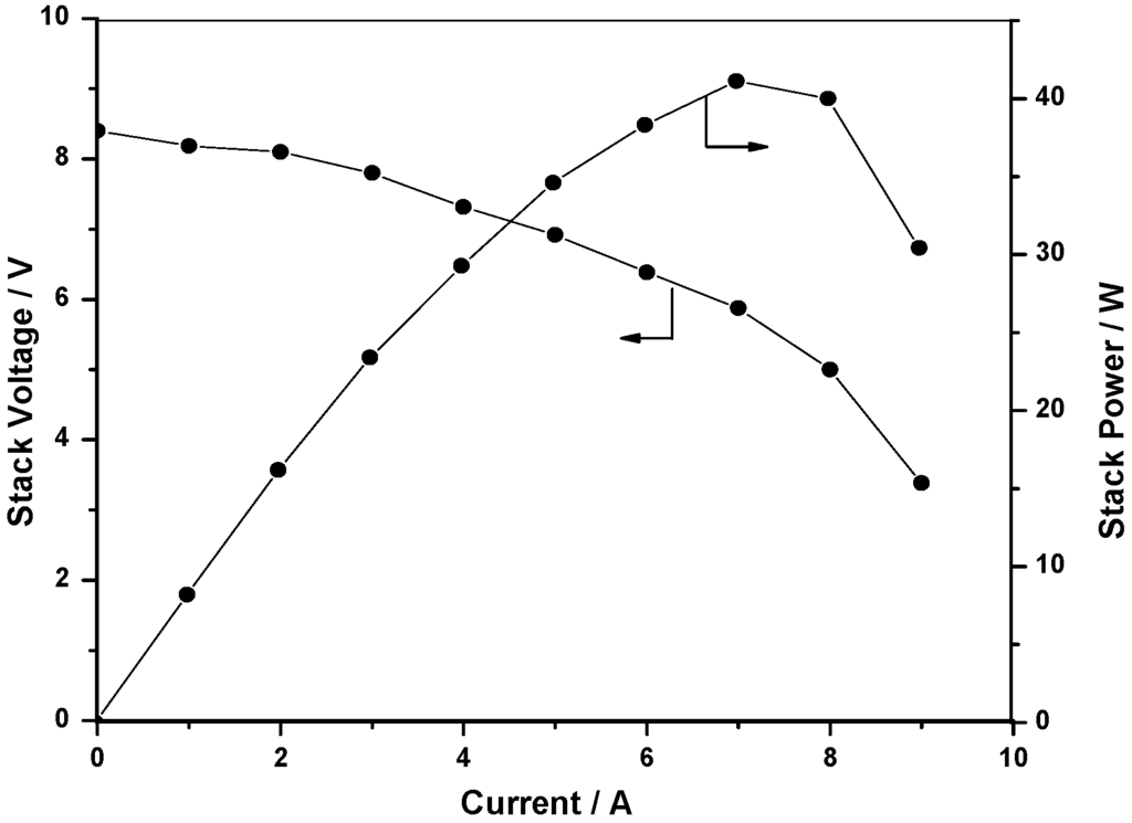
Figure 6.
Polarization data for the DBFC stack.
2.4. Self-supported DBFC system
Optimized solutions of fuel and oxidant are fed to the DBFC system. The system sustains a net power output of 18 W with 2.1 W of auxiliary power consumption with an operational time of about 50 min.
2.5. Operating-time enhancement for the DBFC system
Since NaOH is consumed during the operation of fuel cell, operating time can be enhanced by increasing the concentration of aqueous NaOH. However, a maximum of 25 wt. % of NaOH can only be used, above which the solution viscosity becomes too high to operate the pump. This determines the maximum expected operating time to be ~113 min = 50 min x (25 wt. % / 11 wt. %). It is noteworthy that increasing the aqueous NaOH concentration in the anolyte lowers the cathode performance.
2.6. Safety
The safety issues in the system are addressed by designing the system to handle only the reduced concentration of fuel and oxidant so as to mitigate any undesired side reaction.
3. Experimental
3.1. Membrane electrode assemblies (MEAs)
Membrane electrode assemblies (MEAs) were obtained by sandwiching the pre-treated Nafion®-117 membrane electrolyte between the anode and the cathode. To prepare the anode catalyst layer, slurry of Pt/C obtained by ultra-sonicating the required amount of Pt/C with 7 wt. % of Nafion® solution in isopropyl alcohol was coated on a carbon cloth (Avcarb 1071-HCB, Ballard) with a catalyst loading of 0.5 mg cm-2. To prepare the cathode catalyst layer, slurry of Au/C obtained by ultra-sonicating the required amount of Au/C with 7 wt. % of Nafion® solution in iso-propyl alcohol was coated on carbon cloth with the catalyst loading of 1 mg cm-2. Subsequently, a Nafion® coating of 0.25 mg cm-2 was applied on to the surface of each of the electrodes and the MEA was obtained by hot pressing the electrodes on either side of a pre-treated Nafion-117 membrane under 60 kg cm-2 at 125oC for 3 min.
3.2. Bipolar plate
As shown in Figure 7, serpentine flow-field with an active area of 45 cm2 was used in the single/bipolar plates. Since both the fuel and oxidant used in the stack are ionically conducting, the use of conventional manifolds may cause shorting between the cells when the anolyte and catholyte solutions pass through the manifold [15]. To circumvent this problem, manifolds in the graphite plates were coated with an acid /alkali-resistant epoxy-based adhesive.
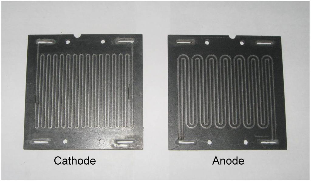
Figure 7.
Bipolar plate with flow field employed for the DBFC stack.
3.3. Stack assembly
The MEAs obtained were sandwiched between graphite flow-field plates. Gold-plated stainless steel sheets were used as current-collectors-cum-endplates. O-ring seating was provided on the circumference of manifolds in the endplates to avoid any leakage between endplates and graphite plates. A DBFC stack was realized by stacking five cells in series. The stack dimensions were 11 cm x 9 cm x 4 cm. The stack assembly was held together with leak-proof Teflon-reinforced gaskets, bolts and nuts.
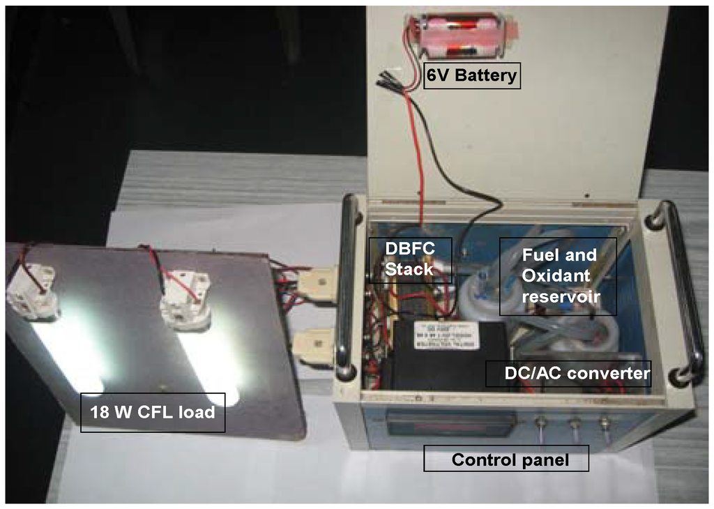
Figure 8.
Self-supported DBFC system.
3.4. Construction and working of self- supported DBFC system
Fuel and oxidant were circulated with the help of two mini-pumps (KNF Neuberger, Inc.) through the respective tanks. Gas vents were provided in both the fuel and oxidant tanks. A cooling fan was fitted to dissipate the heat generated by the fuel cell stack. A 6V battery comprising four AA cells was used as power source for the initial start-up. The control panel of the stack comprised a digital voltmeter to monitor the stack voltage and toggle switches to control the operation of reactant pumps; provision was also made to convert the dc output power to ac. A photograph of such a DBFC system is shown in Figure 8 and its flow sheet is depicted in Figure 9.
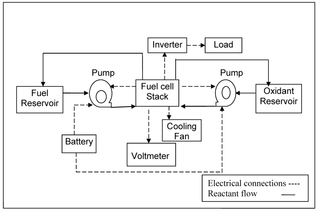
Figure 9.
Flow diagram for the 40W DBFC system along with its auxiliary unit.
3.5. Electrochemical characterization of single cell and multi-cell stack
Performance optimization studies on single cell and stack were carried out with varying concentrations of fuel and oxidant. The fuel comprised aq. NaOH (11 wt. %) with varying amounts of NaBH4 while the oxidant comprised 1.5 M H2SO4 with varying volumes of H2O2. For single cell studies, 40 mL of anolyte and 50 mL of catholyte were fed to the cell while 200 mL of anolyte and 250 mL of catholyte were fed for studies on the stack. For all the studies, both fuel and oxidant flow-rates to single cell and stack were kept at 20 mL min-1 and 100 mL min-1, respectively, and the studies were conducted by recycling the fuel and oxidant solutions using pumps. After installing single cell/stack in the test station, performance evaluation studies were conducted. Galvanostatic-polarization data for the DBFCs operating at room temperature (~ 25oC) were obtained using a Bitrode Battery Charge/Discharge Unit (Model No. LCN 2-10-12 from Bitrode Corporation Fenton, Missouri, US). Fuel and oxidant utilization efficiencies were estimated from chronopotentiometric data recorded galvanostatically by employing an Autolab Electrochemical System (ECO Chemie). The concentrations of NaBH4 and H2O2 in initial and spent (un-reacted) solutions were determined by iodometry [16] and permanganometry [17], respectively, while Na2SO4 was estimated gravimetrically [18].
4. Conclusions
A 40 W self-supported DBFC system is reported for the first time. A critical electrochemical characterization of the system suggests that the operation time is dependent on the concentration of supporting reactants in addition to fuel and oxidant. The optimum concentration of oxidant for single cell is 8 M while it is 2 M for the stack due to rise in temperature and decomposition of the oxidant that would result in reduced availability of oxidant at the electrode surface at increased concentrations.The optimum concentration of NaBH4 to be used in the system is found to be 8 wt. %.
Acknowledgements
Financial support from CSIR, New Delhi through a supra-institutional project during the XI Five Year Plan is gratefully acknowledged. A. K. Shukla thanks US Army Communication-Electronics Research, Development and Engineering Center (CERDEC) for support.
References and Notes
- Larminie, J.; Dicks, A. Fuelling fuel cell. In Fuel Cell System Explained; 2nd Ed.; John Wiley & Sons Ltd: Chichester, West Sussex, England, 2003; pp. 229–308. [Google Scholar]
- Amendola, S.C.; Sharp-Goldman, S.L.; Janjua, M.S.; Spencer, N.C.; Kelly, M.T.; Petillo, P.J.; Binder, M. A safe, portable, hydrogen gas generator using aqueous borohydride solution and Ru catalyst. Int. J. Hydrogen Energy 2000, 25, 969–975. [Google Scholar] [CrossRef]
- Wu, C.; Zhang, H.; Yi, B. Hydrogen generation from catalytic hydrolysis of sodium borohydride for proton exchange membrane fuel cells. Catal. Today 2004, 93-95, 477–483. [Google Scholar] [CrossRef]
- Shukla, A.K.; Jackson, C.L.; Scott, K.; Raman, R.K. An improved-performance liquid-feed solid-polymer-electrolyte direct methanol fuel cell operating at near-ambient conditions. Electrochim. Acta. 2002, 47, 3401–3407. [Google Scholar] [CrossRef]
- Shukla, A.K.; Raman, R.K. Methanol-resistant oxygen-reduction catalysts for direct methanol fuel cells. Annu. Rev. Mater. Res. 2003, 33, 155–168. [Google Scholar] [CrossRef]
- Li, Z.P.; Liu, B.H.; Arai, K.; Asaba, K.; Suda, S. Evaluation of alkaline borohydride solutions as the fuel for fuel cell. J. Power Sources 2004, 126, 28–33. [Google Scholar] [CrossRef]
- Choudhury, N.A.; Raman, R.K.; Sampath, S.; Shukla, A.K. An alkaline direct borohydride fuel cell with hydrogen peroxide as oxidant. J. Power Sources 2005, 143, 1–8. [Google Scholar] [CrossRef]
- Raman, R.K.; Choudhury, N.A.; Shukla, A.K. A high output voltage direct borohydride fuel cell. Electrochem. Solid-State Lett. 2004, 7, A488–A491. [Google Scholar] [CrossRef]
- Raman, R.K.; Prashant, S.K.; Shukla, A.K. A 28-W portable direct borohydride–hydrogen peroxide fuel-cell stack. J. Power Sources 2006, 162, 1073–1076. [Google Scholar] [CrossRef]
- Ponce de León, C.; Walsh, F.C.; Rose, A.; Lakeman, J.B.; Browning, D.J.; Reeve, R.W. A direct borohydride—acid peroxide fuel cell. J. Power Sources 2007, 164, 441–448. [Google Scholar] [CrossRef]
- Miley, G.H.; Luo, N.; Mather, J.; Burton, R.; Hawkins, G.; Gu, L.; Byrd, E.; Gimlin, R.; Shrestha, P.J.; Benavides, G.; Laystrom, J.; Carroll, D. Direct NaBH4/H2O2 Fuel Cells. J. Power Sources 2007, 165, 509–516. [Google Scholar] [CrossRef]
- Cheng, H.; Scott, K. Influence of operation conditions on direct borohydride fuel cell performance. J. Power Sources 2006, 160, 407–412. [Google Scholar] [CrossRef]
- Yang, W.; Yang, S.; Sun, W.; Sun, G.; Xin, Q.J. Nanostructured palladium-silver coated nickel foam cathode for magnesium–hydrogen peroxide fuel cells. Electrochim. Acta 2006, 52, 9–14. [Google Scholar] [CrossRef]
- www.h2o2.com/intro/properties/thermodynamic.html.
- Luo, N.; Miley, G.H.; Mather, J.; Burton, R.; Hawkins, G.; Byrd, E.; Holcomb, F.; Rusek, J. Engineering of the bipolar stack of a direct NaBH4 fuel cell. J. Power Sources 2008, 185, 356–362. [Google Scholar] [CrossRef]
- Lyttle, D.A.; Jensen, E.H.; Struck, W.A. Simple volumetric assay for sodium borohydride. Anal. Chem. 1952, 24, 1843–1844. [Google Scholar] [CrossRef]
- Jeffery, G.H.; Bassett, J.; Mendham, J.; Denney, R.C. Titrimetric analysis. In Vogel’s Textbook of Quantitative Chemical Analysis; 5th Ed.; John Wiley & Sons Inc: New York, NY, USA, 1989; pp. 372–373. [Google Scholar]
- Jeffery, G.H.; Bassett, J.; Mendham, J.; Denney, R.C. Gravimetry. In Vogel’s Textbook of Quantitative Chemical Analysis; John Wiley & Sons Inc: New York, NY, USA, 1989; pp. 490–493. [Google Scholar]
© 2009 by the authors; licensee Molecular Diversity Preservation International, Basel, Switzerland. This article is an open-access article distributed under the terms and conditions of the Creative Commons Attribution license (http://creativecommons.org/licenses/by/3.0/).