


Abstract
With the exponential growth of natural gas reserves and utilization scale in China, underground gas storage (UGS) facilities—critical infrastructure within the natural gas production-supply-storage-sales system—have entered a phase of rapid expansion. As the core component connecting subsurface reservoirs with surface systems, wellbore integrity directly influences operational safety and service lifespan of UGS facilities. However, current leakage detection and integrity analysis methodologies for gas storage wellbores remain deficient in effective real-time monitoring capabilities. Traditional methods, however, are constrained by limited spatial coverage and insufficient precision, rendering them inadequate for comprehensive, continuous safety monitoring requirements. To address this industry challenge, this study proposes a real-time wellbore integrity monitoring framework based on distributed fiber optic sensing technology, integrating distributed temperature sensing (DTS) and distributed acoustic sensing (DAS) devices into a synergistic monitoring system. The DTS component enables preliminary localization of potential leakage points through detection of minute temperature anomalies along the wellbore, while the DAS unit accurately identifies acoustic signatures caused by gas leakage within casings via monitoring of acoustic vibration signals propagating along the optical fiber. Through joint analysis of DTS and DAS data streams, real-time diagnosis of wellbore leakage events and integrity status can be achieved. Field trials demonstrated that this hybrid monitoring system achieved leakage localization accuracy within 1.0 m, effectively distinguishing normal operational signals from abnormal leakage characteristics. During actual monitoring operations, no indications of wellbore integrity compromise were detected; only minor noise and interference signals originating from surface construction activities were observed.
1. Introduction
With the escalating energy consumption demands in China, natural gas—as a clean and efficient energy source—has experienced growing development and utilization [1,2,3]. Salt cavern gas storage represents one of the most critical natural gas storage modalities in China owing to favorable geological conditions, low storage costs, and high collection/utilization efficiency [4,5]. The wellbore serves as a pivotal conduit connecting surface infrastructure with subterranean reservoirs, enabling reservoir monitoring and gas transmission within underground gas storage (UGS) systems while ensuring their safe and efficient operation [6,7]. However, damage to wellbores induced by the complex subsurface environment of UGS facilities poses significant safety risks to operational integrity. Conventional monitoring approaches face limitations in achieving real-time comprehensive surveillance, frequently failing to detect minor structural impairments in underground infrastructure at early stages. Moreover, underground monitoring operations are inherently challenging and resource-intensive, thereby struggling to satisfy the operational requirements for maintaining efficient and secure UGS functionality [8].
The wellbore leakage of natural gas from underground gas storage induces ambient temperature fluctuations and acoustic vibrations. As an emerging monitoring methodology, distributed optical fiber sensing technology offers distinct advantages through its distributed sensing architecture, continuous operation, and real-time monitoring capabilities. By analyzing attenuation and variation in propagating optical signals within the fiber, this technology can detect environmental and structural changes occurring near the deployed cable in wellbores [9,10], thereby enabling non-invasive and comprehensive monitoring. Among its various applications, distributed temperature sensing (DTS) and distributed acoustic sensing (DAS) represent two critical implementations for underground gas storage monitoring [11,12,13]. The DTS technique employs Raman scattering effects combined with Optical Time Domain Reflectometry (OTDR) to achieve temperature measurement and spatial localization along fiber optic cables. Concurrently, DAS utilizes Rayleigh scattering interference phenomena alongside OTDR technology to perform continuous distributed detection and quantitative analysis of acoustic emissions surrounding the fiber cables. Specifically, DTS monitors downhole structural temperature distributions by measuring thermal variations along adjacent optical fibers, allowing detection of potential integrity breaches through anomalous temperature patterns. Complementarily, DAS enables precise localization of acoustic vibrations through sound wave analysis near fiber cables, providing real-time insights into downhole facility damage and deformation following data interpretation [14,15,16].
Therefore, distributed optical fiber sensing technology is used to monitor the wellbore leakage of underground gas storage. Based on the DTS and DAS technology, a theoretical model of wellbore leakage can be studied and the monitoring of wellbore integrity through the cable for underground gas storage can be analyzed. By analyzing the monitoring results, the feasibility of using distributed optical fiber technology to monitor the safety of the underground gas storage can be studied. The distributed sensing characteristics of optical fiber can realize real-time monitoring of the gas storage wellbore leakage, replacing the comprehensive monitoring which is difficult to achieve by traditional monitoring means. On the one hand, it can realize the non-invasive and continuous monitoring of the gas storage wellbore integrity. On the other hand, it can improve the safety operation level of the gas storage. Distributed optical fiber technology can more quickly and accurately detect wellbore leakage and damages, effectively improving the emergency response ability of the gas storage, and reducing safety risks. This study aims to explore the application prospects of the distributed optical fiber sensing technology in the wellbore integrity monitoring of underground gas storage, provide technical support for improving the monitoring level of China’s gas storage, improve the monitoring level of China’s gas storage, and promote the safe and efficient operation of underground gas storage.
2. Distributed Optical Fiber Sensing Technology
Distributed optical fiber sensing technology not only uses optical fiber as sensing medium, but also uses optical fiber as transmission medium. The function of distributed measurement of physical parameters to be measured in the external environment can be realized through a common optical fiber and a matching demodulation and signal processing system. Distributed fiber sensing is based on the Rayleigh scattering, the Raman scattering and the Brillouin scattering generated when light is transmitted in the fiber to measure the change in various environmental physical parameters. At present, the mature distributed optical fiber sensing systems mainly include phase sensitive Optical Time Domain Reflectometry (Φ−OTDR) and its DAS system based on the Rayleigh scattering, the DTS system based on the Raman scattering, and the Brillouin optical time domain analyzer (BOTDR) based on the Brillouin scattering [17]. The following mainly introduces the distributed optical fiber acoustic vibration sensing detection technology and the distributed optical fiber sensing temperature measurement technology for wellbore gas leakage monitoring and integrity analysis of the underground gas storage.
2.1. Acoustic Vibration Sensing Detection
- (1)
- Principles and advantages of the DAS technology
The testing system of DAS technology primarily comprises an optical fiber sensor, fiber laser, fiber grating, photodetector, data acquisition unit, and data processing unit. As the core component of the DAS system, the optical fiber sensor consists of an optical fiber coupled with an acoustic transducer. The optical fibers employed are typically single-mode fibers, while the acoustic transducers may be piezoelectric, electromagnetic, or optical in nature. The fiber laser serves as the light source for the fiber sensor, commonly operating in continuous-wave mode. The fiber grating functions as a wavelength division filter within the optical fiber sensor system, enabling separation of propagating optical signals into distinct spectral components. A photodetector operates as the optical receiver that converts the transmitted optical signals into corresponding electrical signals. The data acquisition unit performs analog-to-digital conversion of the detected optoelectronic signals before transmitting these digital outputs to the central processing unit. The data processing unit constitutes the analytical core of the DAS system, responsible for signal interpretation and generation of structural and environmental monitoring parameters through computational analysis of the acquired digital data streams.
The work principle of this system is as follow. Start the laser light source and the photodetector, and use the pulsed laser source to inject light pulses into the optical fiber for a short time, and the light pulses will be affected by the outside world while propagating in the optical fiber. The system then begins to continuously detect and record signals of phase or amplitude changes at various locations of the optical fiber. Through digital signal processing, this DAS system analyzes and locates the signal to determine whether there is an abnormal change point, that is, the leakage point in this paper.
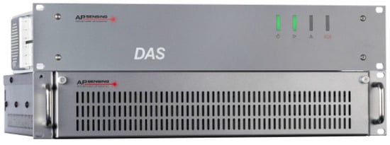
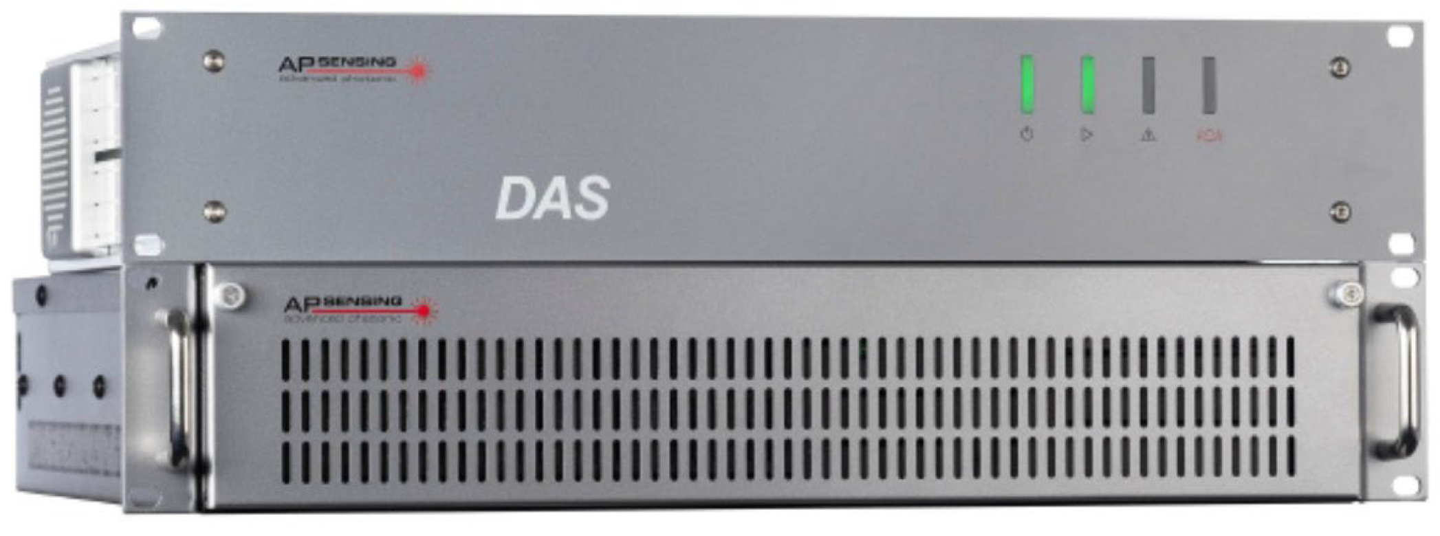
There are many advantages of the DAS applications. First, it enables continuous and distributed monitoring of very long-distance targets. Compared with the traditional point detection method, the coverage area is much larger. Secondly, the fiber itself is small in size and strong in stretchability, and can be flexibly deployed according to actual needs. This is a good fit for in-wellbore monitoring. In addition, the fiber optic sensor itself has no electromagnetic interference, and will not affect other equipment when monitoring in the wellbore. Finally, the optical fiber sensor has the characteristics of long-term stable operation, and the monitoring reliability is high. Taking German AP Sensing (Böblingen Germany) DAS as an example, the main performance parameters are shown in Table 1 and Figure 1.
Table 1.
Distributed optical fiber DAS devices and main performance parameters.
Figure 1.
A DAS device for the high precision monitoring of acoustic vibration along with the distributed optical fiber in the wellbore.
DAS technology offers distinct advantages including passive operation, independence from electrical power, resistance to electromagnetic interference, capability for long-distance and wide-area monitoring, real-time data acquisition, and high spatial resolution. These characteristics demonstrate significant application potential in geological hazard monitoring, environmental surveillance, and structural health monitoring fields [18,19,20]. In structural health monitoring applications, DAS employs distributed optical fiber sensors to detect acoustic signal variations, enabling continuous real-time monitoring of engineering structures such as buildings and bridges. This facilitates comprehensive assessment of structural integrity through deformation measurement and crack detection, with notable advantages including high sensitivity, extended monitoring ranges, and continuous real-time deformation tracking capabilities. For geological hazard monitoring, DAS systems can identify subsurface anomalies including land subsidence and fracture activity by analyzing acoustic signal modifications along optical fibers deployed in high-risk zones, thereby providing critical technical support for early warning systems. In environmental monitoring contexts, this technology enables water quality assessment through acoustic characterization of rivers and lakes via fiber-optic sound wave detection, while also facilitating ecological analysis through monitoring of biophonic signals in natural environments like forests to track faunal and floral dynamics.
- (2)
- Applications of DAS technology in underground gas storage
When the optical fiber cable is subjected to sound waves of the wellbore leakage, its internal structure of the cable is disturbed. At this time, the acoustic signal will modulate the optical signal by changing the refractive index of some areas of the fiber. Specifically, when sound waves pass through an optical cable, the distribution of refractive index inside the optical fiber of the cable changes. Once light passes through these regions, the phase of the light differs from other regions because the refractive index is no longer uniform. Acoustic information embedded in the optical signal can be extracted by detecting phase or amplitude changes in the light output. Given that the phase delay of a light wave passing through an optical fiber of length L is , then:
where n is the refractive index of the fiber, is the propagation constant of the light wave in the fiber, and k is the wave number of the light wave in vacuum.
Fully differentiating the delay phase in Equation (1) gives:
where is the axial stretching of the optical fiber under stress, is the change in refractive index of optical fiber core caused by photo elastic effect, and is the change in wavenumber. As can be seen from Equation (2), the factors that cause phase delay are axial stretching , the change in refractive index and wavenumber variation .
DAS system offers capabilities for continuous real-time monitoring of wellbore gas leakage and structural integrity in underground gas storage facilities. Firstly, optical fiber sensors can be installed on the inner wall of the casing string within the wellbore to detect potential leaks through acoustic signal variations. Leak locations can be precisely determined by analyzing dynamic changes in acoustic waveforms. Secondly, strategic deployment of fiber optic sensors across different wellbore segments facilitates comprehensive distributed monitoring along the entire well path. Once acoustic vibration anomalies are detected, this DAS system enables precise localization of leakage points. Finally, the implementation of distributed monitoring allows sustained real-time assessment of wellbore integrity parameters, thereby enabling the proactive identification of potential safety risks associated with gas migration before critical failures occur.
2.2. Temperature Sensing Measurement
- (1)
- Testing principles of the DTS technology
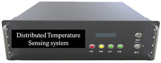
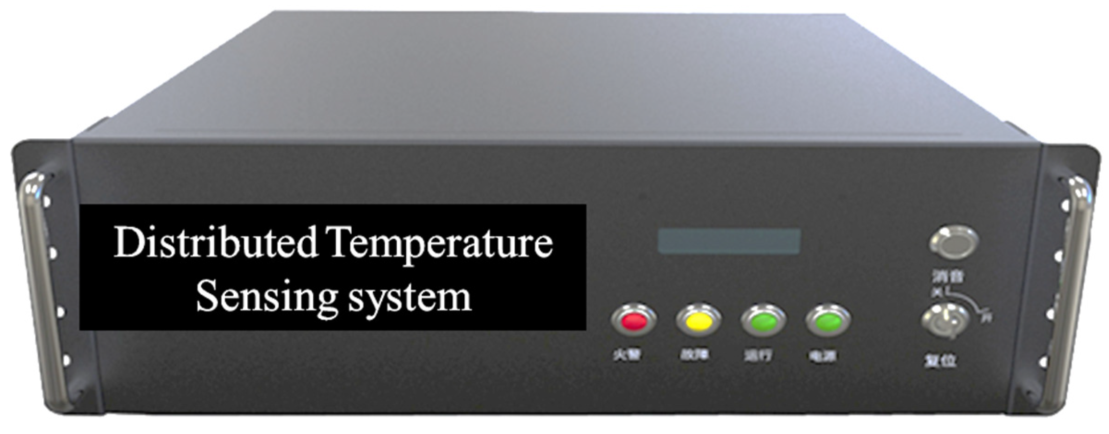
The DTS technology is a new technology that uses optical fiber sensors to monitor and record temperature. This technology uses a distributed sensing optical fiber as a temperature detection sensor, uses the principle of temperature optical property change in the material inside the optical fiber according to the Raman scattering principle, and reflects the temperature change in different locations through the intensity change in the photoelectric signal transmitted by the optical fiber according to the OTDR technique [21,22,23]. A DTS system is shown in Figure 2.
Figure 2.
A DTS device for the high precision monitoring of temperature change along with the distributed optical fiber in the wellbore.
When the optical light is transmitted in the cable, it will interact with the molecules in the fiber and scatters. The scattering that occurs includes Rayleigh scattering and Raman scattering. Raman scattering is the result of the interaction between the photon and the molecular thermal motion. Some photons obtain heat energy from the molecule, their energy decreases, and the wavelength becomes longer to produce the Stokes light. Some of the photons pass energy to the molecule, and their own energy increases and the wavelength becomes shorter to produce the anti-Stokes light. The wavelength offset of Stokes light and anti-Stokes’s light depends on the Raman frequency spectrum of the molecules in the fiber, which is related to the chemical composition and structure of the molecules. Two of the light intensities are related to temperature as follows:
Stokes’s light intensity:
Anti-Stokes’s light intensity:
where is Is and Iα are the intensities of the Stokes light and anti-Stokes light, respectively. λs and λα are the wavelengths of the Stokes light and the anti-Stokes light, respectively. h is the Planck’s constant. c is the speed of light in vacuum. k is the Boltzmann’s constant. Δγ is the offset wave number. T is the absolute temperature.
The intensities of Stokes and anti-Stokes light at identical spatial positions are proportional to temperature according to established theoretical relationships. To enhance measurement accuracy and mitigate systematic errors inherent in optical sensing systems, our DTS system employs a dual-channel dual-wavelength demodulation technique that utilizes the intensity ratio between these two Raman-scattered signal components. The implementation procedure comprises three sequential stages: First, both anti-Stokes and Stokes light are independently collected through dedicated detection channels. Given its superior thermal sensitivity, the anti-Stokes component serves as the primary signal channel while the Stokes component functions as a reference channel to compensate for instrumental drift and system noise. Second, the intensity ratio between anti-Stokes and Stokes signals is calculated to effectively eliminate common-mode errors, thereby isolating the genuine temperature-dependent signal. Finally, based on the established proportional relationship between this normalized intensity ratio and absolute temperature, spatially resolved temperature distributions are determined through application of the fundamental principles of spontaneous Raman scattering. The mathematical formulation governing this temperature retrieval process is expressed as follows:
where T0 is a fixed temperature, R(T) is the ratio of anti-Stokes’s light intensity to Stokes’s light intensity.
The DTS system uses the above principles to pass the laser through the entire fiber and collect the Raman scattering signals and R(T) generated at various locations. After repeating this process, the distributed temperature data of different sections in the fiber can be obtained by using the R(T), and the distributed temperature monitoring function of the DTS system can be realized.
- (2)
- Applications of DTS technology in underground gas storage
The application of DTS technology for temperature monitoring in deep wellbores of underground gas storage facilities comprising multiple wellbores offers significant advantages. Traditional single-point sensors require individual installation at each wellbore location, resulting in high costs and limited monitoring coverage that hinders comprehensive surveillance. In contrast, distributed optical fiber sensing technology enables embedding the entire optical fiber within the inner wall of the wellbore structure, utilizing the intrinsic distributed sensing capability of the optical fiber to achieve real-time temperature monitoring across all wellbores within the gas storage facility. This approach substantially expands spatial monitoring coverage while requiring only a single optical fiber deployment, thereby significantly reducing operational costs. Concurrently, this technology provides real-time response capabilities, enhanced stability, and reliability, enabling prompt detection of temperature variations across different wellbore segments and facilitating timely identification of potential safety hazards within the gas storage system. Furthermore, the optical fiber sensing system demonstrates minimal interference with gas storage operations through concealed installation, eliminates electromagnetic interference during data transmission, and maintains superior security performance. The system also exhibits excellent scalability, as additional monitoring points can be incorporated by extending the optical fiber length without disrupting existing infrastructure. A representative DTS device configuration is illustrated in Figure 2, with its key performance parameters summarized in Table 2.
Table 2.
The main performance parameters of the DTS device.
3. Downhole Optical Cable Design and Permanent Monitoring System
In order to realize the wellbore gas leakage monitoring and integrity analysis integrity of underground gas storage based on distributed optical fiber sensing technology, a downhole optical cable is designed and applied in the wellbore and then an integrated permanent monitoring system is provided.
3.1. Design of Downhole Optical Cable and Installation
- (1)
- The design of armored photoelectric composite cable
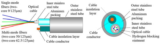
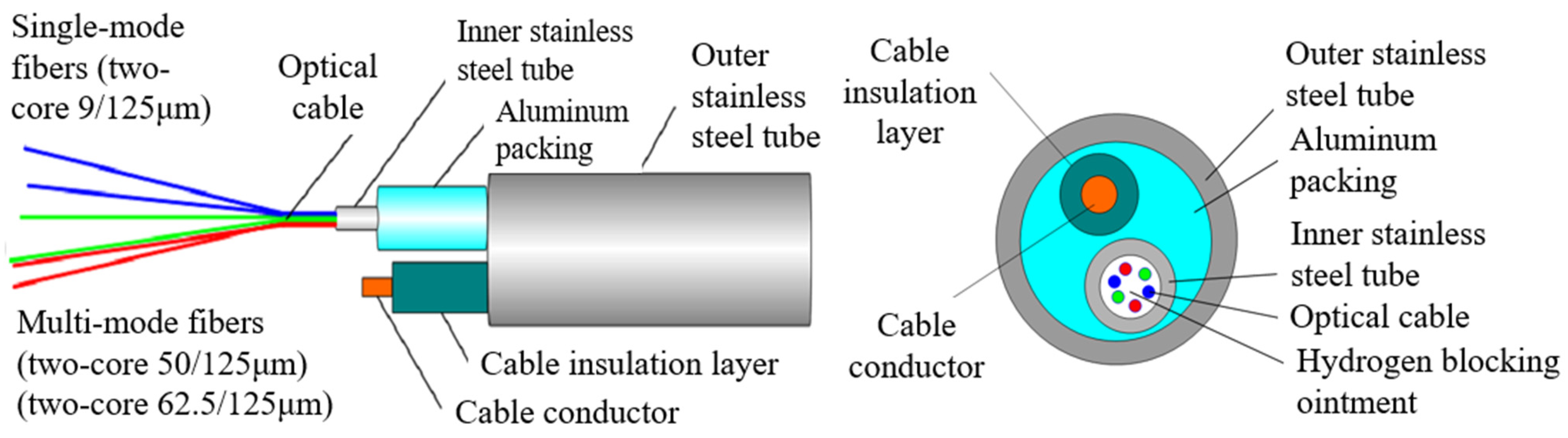
An armored photoelectric composite cable was specifically designed to withstand the complex environmental conditions of high-temperature and high-pressure salt caverns, enabling real-time monitoring of wellbore gas leakage and structural integrity. This composite cable integrates both optical and electrical functionalities through its dual-cable architecture: an optical cable containing two single-mode fibers (9/125 μm) dedicated to distributed temperature sensing (DTS) and four multi-mode fibers (dual 50/125 μm cores and dual 62.5/125 μm cores) configured for dynamic acoustic sensing (DAS); and a power cable providing continuous electrical supply to downhole pressure gauges and mounting brackets. All optical fiber connections are permanently terminated using FC/APC connectors. The cable’s layered construction comprises concentric components including an outer stainless-steel tube, aluminum packaging layer, inner stainless-steel tube, optical assembly, hydrogen-blocking compound, dielectric insulation layer, and central conductor, as detailed in Figure 3. Key technical specifications of this armored photoelectric composite cable are summarized in Table 3.
Figure 3.
The design of the armored photoelectric composite cable for the downhole wellbore.
Table 3.
The main parameters of the armored photoelectric composite cable.
- (2)
- The installation of the armored photoelectric composite cable
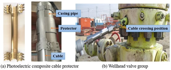
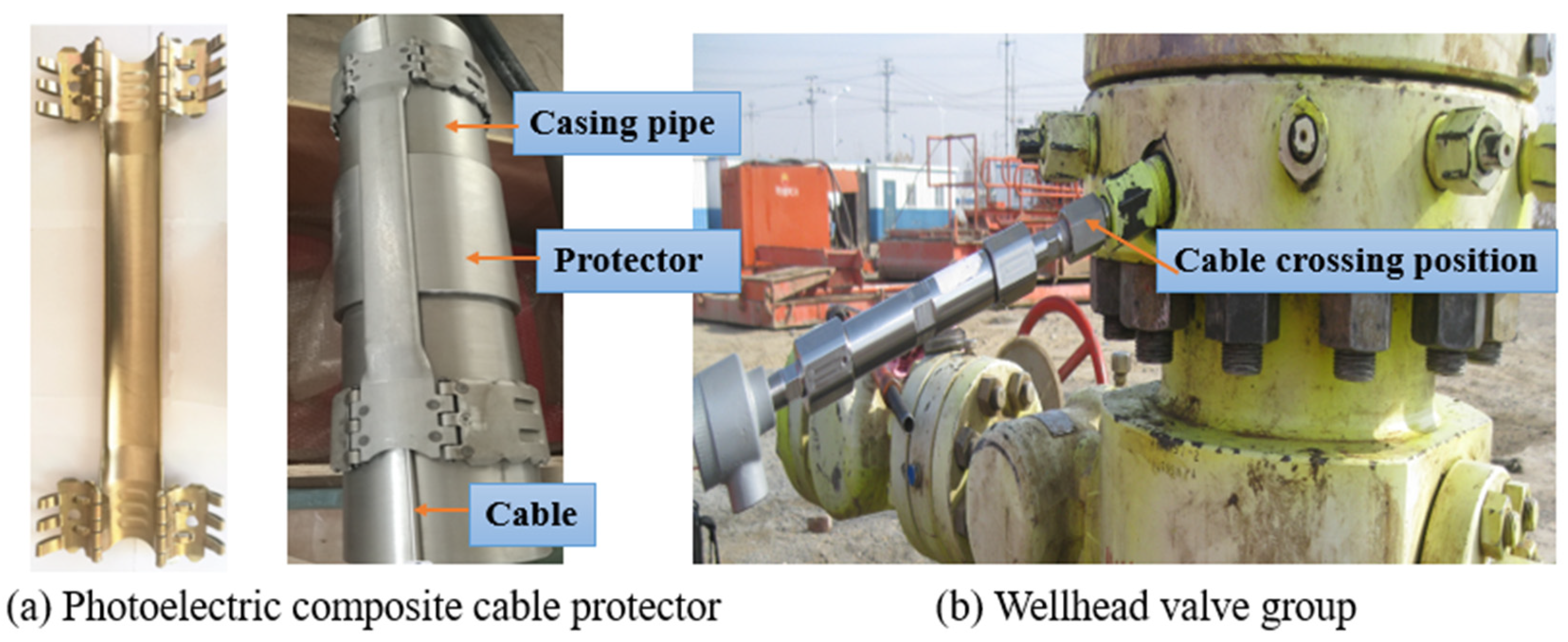
After the end of the optical cable is welded, the end treatment device is fixed on the tubing wall, and the engineer installs the optical cable protector on the first 7″ tubing coupling, paying attention to the fiber and cable as far as possible not to distort. Then, a cable protector shown in the left of Figure 4 is installed at each tubing coupling of the casing string in turn until the wellhead, and a special safety valve cable protector is used above and below the safety valve. The protector of the optical cable is mainly used to protect the optical cable against smashing and bumping during the process of running the optical cable into the well. The optical cable is firmly held on the outer wall of the oil tube in each collar. The manometer tube support tool is connected with the casing string in series, the manometer is fixed to the manometer tube, and the manometer sensor is sealed with the pressure transmitting port in the casing string of wellbore.
Figure 4.
The installation of the armored photoelectric composite cable in the wellbore.
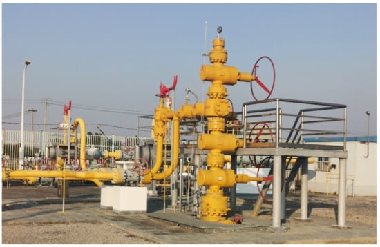
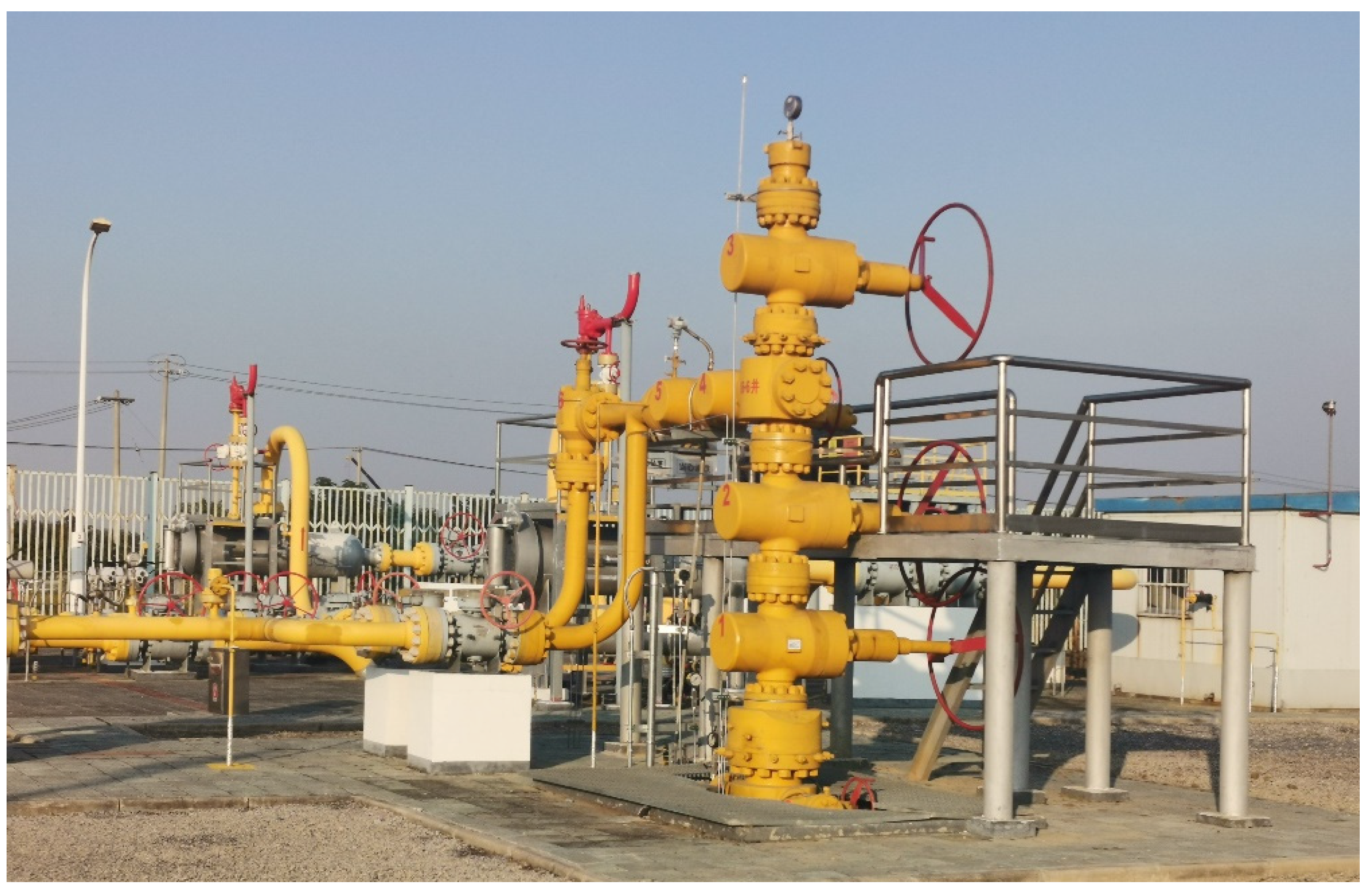
Following completion of connections, the pressure gauge and pressure transmission port must be configured to withstand a 35 MPa pressure test, with well commissioning permitted only after successful qualification. Prior to routing through the tubing hanger, sufficient optical and power cable lengths should allocated to extend from the wellhead through the tubing hanger, traverse the gas production tree’s flanking top wire position as illustrated in Figure 4 (right side), and terminate at the designated distribution room. The gas production tree assembly incorporates a dedicated pass-through bore for installing the wellhead outlet assembly (WHO) featuring a 1/2″ NPT female connector. Buried cables are routed to the wellsite distribution room and connected to both the pressure gauge data acquisition system and cable terminal junction box. The casing string hanger and wellhead assembly are integrated with the injection and production string, followed by a comprehensive pressure test conducted collectively after surface gas production tree installation. Optical and electrical signal integrity are verified at intervals of 100 m and 300 m during cable deployment operations.
3.2. An Integrated Permanent Monitoring System of Wellbore
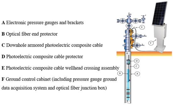
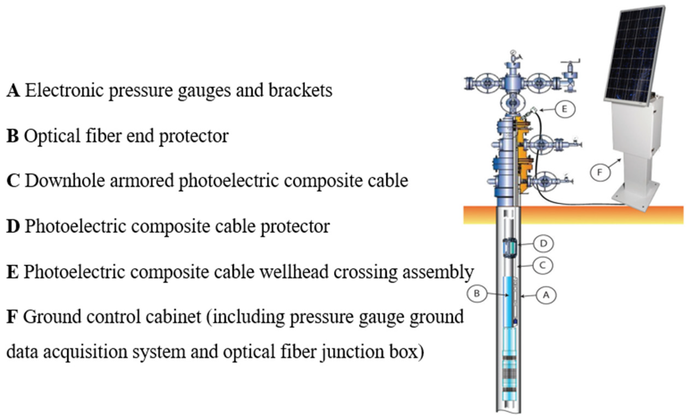
A permanently installed integrated monitoring system for downhole temperature, pressure, and wellbore gas leakage was deployed utilizing distributed acoustic sensing (DAS) and distributed temperature sensing (DTS) technologies through the installation of optical fibers and permanent downhole pressure gauges within an underground gas storage wellbore. The system comprises electronic pressure gauges with mounting brackets, an optical fiber end protector, downhole armored photoelectric composite cable, photoelectric composite cable protector, wellhead crossing assembly, and a ground control cabinet housing a pressure gauge data acquisition system and optical fiber junction box. The optical fiber component of the photoelectric composite cable enables continuous monitoring of temperature distribution and acoustic vibration profiles along the wellbore annulus via combined DAS and DTS signal interrogation, providing critical data support for analyzing wellbore integrity and leakage characteristics. This monitoring capability is accessible at the surface junction box through DTS + DAS technologies and downhole pressure measurements as required. The schematic diagram of this permanently installed wellbore monitoring system is presented in Figure 5. The term ‘permanent monitoring system’ refers to its fixed installation design intended for long-term continuous operation. The reported data were collected during a 72 h initial validation test following system commissioning, while the system remains operational for sustained monitoring applications.
Figure 5.
The integrated permanent monitoring system of wellbore during the application.
- (1)
- The underground design of integrated permanent monitoring system
The real-time evaluation of wellbore gas leakage conditions and integrity analysis of wellbore cable can be realized in the annulus of casing strings under the premise of not occupying wellbore production time in the gas storage. The armored composite cable settled in the annulus is used to monitor the wellbore gas leakage and integrity analysis of wellbore cable. The main monitoring parameters of this system are temperature, acoustic vibration and downhole pressure. The distributed temperatures along with the cable are obtained by using the DTS system. The distributed acoustic vibrations along with the cable are obtained by using the DAS system. The downhole pressure gauges can continuously monitor the pressure and temperature changes in the wellbore in real time, providing data and curve analysis for production command. The real-time downhole data is stored in the surface data acquisition system and can be transmitted remotely through the wired communication module. The bottom hole temperature and pressure monitoring part is composed of a pressure gauge and a support cylinder. The downhole pressure and real-time changed temperatures are real-time monitored by using the downhole permanent pressure gauges shown in Figure 5.
- (2)
- The ground part of this monitoring system
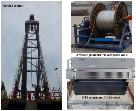
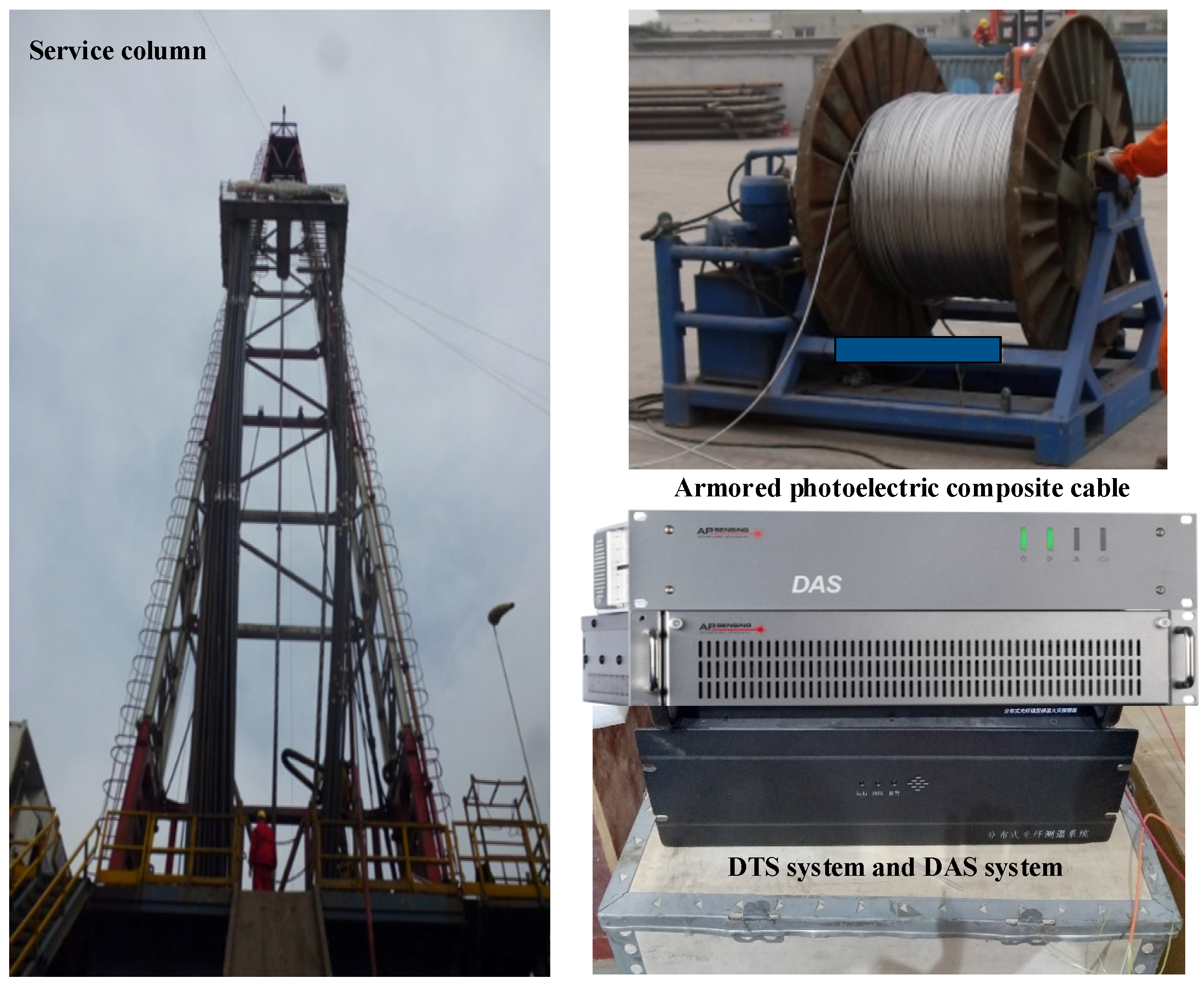
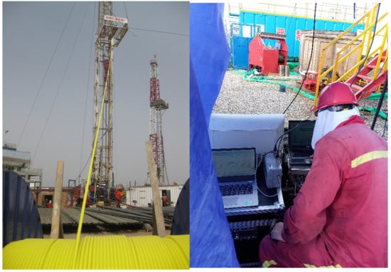
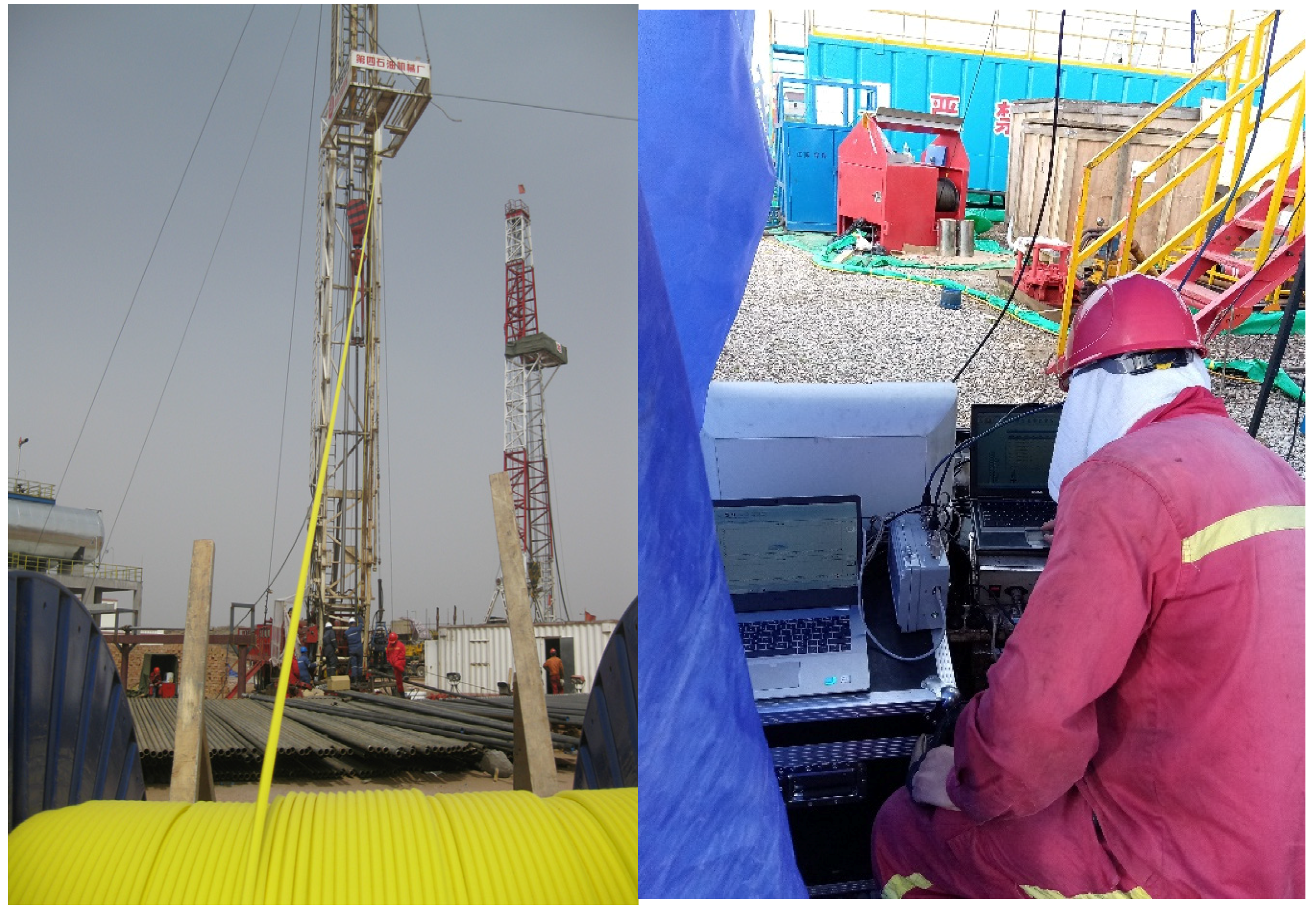
The surface component primarily comprises tubing suspended through a connector, the wellhead assembly via the main valve, ground data optical cables, and the surface control cabinet housing the ground data acquisition system for pressure gauges and the optical fiber junction box. The data acquisition system encompasses surface control, data visualization, data storage, and auxiliary functions including data input/output interfaces and power supply for downhole instruments, while simultaneously collecting and storing data signals from downhole pressure gauges. The optical fiber terminates at the optical fiber junction box, facilitating real-time monitoring of DAS and DTS signals within the annulus. Each monitoring procedure only requires connecting the monitoring data line to the corresponding port on the optical fiber junction box. Wellbore gas leakage characteristics derived from annular DAS and DTS data can be obtained through the monitoring instrumentation. During downhole operations, a photograph of the surface component of this monitoring system is presented in Figure 6.
Figure 6.
The ground part of this monitoring system during the downhole operation process with the help of the service column.
4. Wellbore Leakage Monitoring and Its Integrity Analysis
The wellbore leakage monitoring and integrity analysis method for the cable are proposed in the underground gas storage by using distributed optical fiber sensing technology. The feasibility of this technology is verified by wellbore monitoring and some application tests on specific wellheads were conducted accordingly.
4.1. Wellbore Gas Leakage Monitoring Method
The complex geological conditions of underground salt formations subjected to long-term natural gas storage result in subsidence and plastic deformation of the salt layers. This geomechanically response alters the pressure differential across the reservoir boundaries, leading to progressive deformation and compromised structural integrity of the wellbore. These microstructural failures create preferential pathways for natural gas migration from the reservoir to surface environments through an exceptionally slow and persistent seepage mechanism. The minimal volumetric flux associated with salt formation leakage prevents measurable temperature anomalies from developing, as the thermal energy released during gas exfiltration through microfractures proves insufficient to induce significant ambient temperature variations in the short term. Conventional monitoring methodologies employing temperature or acoustic vibration sensors demonstrate limited efficacy in detecting such diffuse leakage patterns characterized by low flow rates. While catastrophic wellbore failures generate distinct thermal or acoustic signatures, minor leaks remain challenging to identify at early stages due to their subtle manifestation. Effective early warning systems require integrated multi-parameter monitoring frameworks capable of discerning these incremental geochemical and geophysical indicators over extended observation periods, thereby enabling timely detection of nascent leakage phenomena within wellbore structures.
Therefore, DTS technology and DAS technology are combined and used to monitor the wellbore leakage and the integrity analysis of underground gas storage wells. When the wellbore integrity of underground gas storage is damaged or the cable is damaged during the downhole operation, the original physical law of energy conservation can be changed. The Bernoulli equation of fluid moving along the flow line is satisfied energy conservation. The expression is as follows:
where p1 is the pressure intensity of the leaking natural gas inside the wellbore, ρ1 is the density of the natural gas, v1 is the leaking volume of the gas, h1 is the leaking position of the gas, p2 is the pressure intensity of the annulus protection fluid outside the wellbore, ρ2 is the density of the fluid, v2 is the volume of the fluid, and h2 is the leak point in the annulus of the casing strings.
From the Bernoulli Equation (8), it can be observed that local variations in gas flow rate within the annulus casing strings will induce corresponding pressure changes at leakage points. In DAS systems, phase shifts in the optical fiber enable measurement of acoustic vibrations surrounding the wellbore, thereby identifying leak point h2 through these dynamic strain signals. When wellbore integrity is compromised, the associated temperature reduction near the breach allows distributed temperature monitoring along the cable using Raman scattering effects in the fiber, with leak localization in the annular space achieved via DTS technology. The operational frameworks for DTS and DAS applications in wellbore monitoring are illustrated in Figure 7. Additionally, leakage detection thresholds are established as: (1) DTS Threshold—a sustained temperature deviation (ΔT) exceeding ±0.5 °C from the geothermal baseline trend, persisting for >30 min, constitutes a potential thermal anomaly; (2) DAS Threshold—an average acoustic energy increase >6 dB above site-specific background levels within the 100–500 Hz frequency band, spatially correlated across ≥3 consecutive sensing points, indicates a potential acoustic anomaly. These initial threshold parameters, derived from field calibration data, may require empirical adjustment based on specific site conditions. They may also require a localized, sustained positive temperature anomaly (due to the Joule-Thomson effect upon gas expansion) coupled with a broadband increase in acoustic energy (due to turbulent gas flow). The magnitude of these changes would scale with leak rate and pressure differential.
Figure 7.
The application scenarios of the DTS device and DAS device for the wellbore monitoring of underground gas storage.
Therefore, the wellbore leakage and its integrity analysis method can be realized by following these steps: First, the temperature around the underground wellbore of the salt cavern gas storage should be real-time monitored by using the DTS system. The temperature change along the cable from the wellhead to the bottom of the wellbore should be considered reasonable or not according to the long-time monitoring data. The integrity analysis of wellbore and the sensing cable can be initially judged. Secondly, the DAS system should be used to analyze the acoustic signal around the wellbore, and the weak acoustic vibration caused by external interference should be comprehensively considered, such as the knocking along the optical cable. If the DTS system detects the change trend of temperature along the wellbore basically conforms to the facts—that is, the temperature increases gradually from top to bottom and also match the detected data—there is no gas leakage in the wellbore. If the DAS system detects that the signal along the wellbore is normal and can sense the wellhead tapping operation and the acoustic vibration of the external sound source vehicle in the well site, there is no abnormal signal of gas leakage from the inside casing strings and the integrity of the wellbore can be determined. Therefore, the wellbore leakage monitoring and its integrity analysis of the cable can be determined.
4.2. Wellbore Integrity Analysis Process
- (1)
- Ground testing before downhole to ensure equipment working properly.
The fiber optic cable is fused with the FC/APC standard interface, the multi-mode optical fiber interface is inserted into the DTS device, and the single-mode optical fiber interface is inserted into the DAS device. Power on for 2~10 min, to detect and verify whether the temperature along the cable measured by the DTS device is consistent with the ground site temperature, and whether the acoustic vibration measured by the DAS device is consistent with the ground site construction noise. If necessary, tap the armored photoelectric composite optical cable to recheck the DAS signals. If the check is consistent, it proves that the cable is intact before downhole into the wellbore.
- (2)
- Downhole testing to monitor the changes in DTS + DAS signals in the wellbore.
The methodology commences by re-establishing the optical fiber connection to the DTS + DAS instrumentation and verifying the normal operational status of all equipment. Subsequently, temperature distribution data are acquired along the wellbore cable to validate both the original formation temperature profile and the presence of annular protective fluid. Temperature consistency between the measured values and those expected along the optical cable demonstrates cable integrity preservation, enabling precise temperature trend monitoring via DTS instrumentation. Concurrently, acoustic vibration profiles are collected along the wellbore cable using DAS equipment for real-time downhole process monitoring. Baseline measurements establish acoustic vibration characteristics under static conditions and in response to external noise sources. Minimal variation in acoustic signal amplitude along the wellbore under static conditions confirms the DAS system’s capability for reliable acoustic vibration integrity monitoring within the wellbore environment.
- (3)
- After the on-site testing and verification is completed, the collected DTS and DAS data will be saved and brought back for later fine analysis and chart display.
In the event of a leak or compromised integrity in the monitored wellbore, prompt corrective actions must be initiated. For wellbore failures, it is essential to identify the failure type to formulate an appropriate response. Downhole repairs should be conducted when the failure is temporary in nature and amenable to repair. In cases of permanent and irreparable damage, consideration should be given to well abandonment, production cessation, or temporary continued production under safe conditions to maximize economic returns. If workover operations prove unsuccessful, they should be terminated promptly. Equipment replacement decisions must follow economic viability principles, such as substituting corroded tubing sections in shallow intervals with severe corrosion. Detection of casing cement ring leakage necessitates short-term production continuation followed by well abandonment.
5. Application Results and Analysis
In order to verify the feasibility of wellbore leakage monitoring and integrity analysis method base on DTS + DAS distributed optical fiber sensing technology, it is necessary to conduct application tests on specific wellheads and show some applications in the wellbore of salt cavern gas storage. For example, we designed a DTS + DAS monitoring scheme and a downhole photoelectric composite cable is installed in the annulus of wellbores at a salt cavity No. XX of the gas storage. This well is located near the Jintan District, Changzhou City, Jiangsu Province, China. The salt rock top depth is 987.0 m and its salt bottom depth is 1095.0 m, and the thickness is 108 m. The drilling depth of this well is 1095 m and its casing depth is 1005.85 m. The total volume of this salt cavity is 77,102 m3, and the designed operating pressure of the cavity is 7~17 MPa. Therefore, this application of the wellbore leakage monitoring and its integrity analysis can illustrate the effect of using DTS and DAS technologies for underground wellbore of Jintan salt cavern gas storage [24]. This application site of the wellbore leakage monitoring and its integrity analysis is shown in Figure 8.
Figure 8.
The application site of wellbore leakage monitoring and integrity analysis for underground gas storage.
5.1. DTS Testing Results and Analysis
One of the multi-mode optical fibers is selected as the temperature testing of the DTS device before the armored photoelectric composite cable go on the downhole operation in the well. The temperature distribution of the cable is monitored and shown in Figure 8. The temperature curve in the figure is the change in the ground armored photoelectric composite cable after the exposure of the wooden frame coil. There is a significant temperature difference between the upper coil under the exposure and the bottom cable in the shade, which conforms to the basic fact. It can be proved that the multi-mode fiber is intact before the fiber optic cable operation according to the temperature testing results of Figure 9 by using the DTS device.
Figure 9.
The temperature testing results of the DTS device before downhole operation of cable.
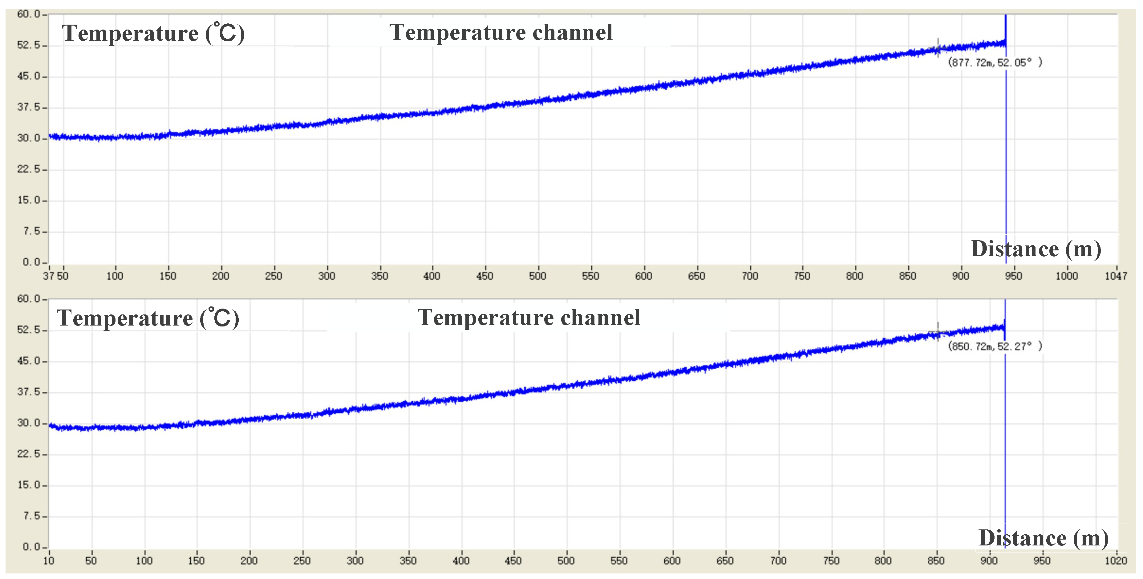
After running the cable to the predetermined position, two multi-mode fibers were selected and inserted into two channels of the DTS system to form the temperature curves from the wellhead to the bottom of the well, and the characteristics of the temperature curves were obtained by comparing the two channels and shown in Figure 10. The temperatures are obtained by using the DTS system after the downhole operation process of the cable in the well. The temperature change curve from the wellhead to the bottom of the well is consistent with the trend of gradual rise in the top-down temperature in the wellbore and the temperature change law of original formation temperature. The tested temperature distribution law is consistent with the original formation temperature distribution law [25,26,27], and this proves that the integrity of the wellbore cable has not been damaged and there is no leakage. In addition, the temperature changes and trends of different channels obtained by the DTS system from different fibers of the cable are basically the same. Another, there is no abnormal temperature point and this illustrated there is no gas leakage. These further comparative analyses verify that the integrity of the wellbore has not been damaged.
Figure 10.
Temperature data monitoring along two multi-mode optical fibers after downhole operation of the cable.
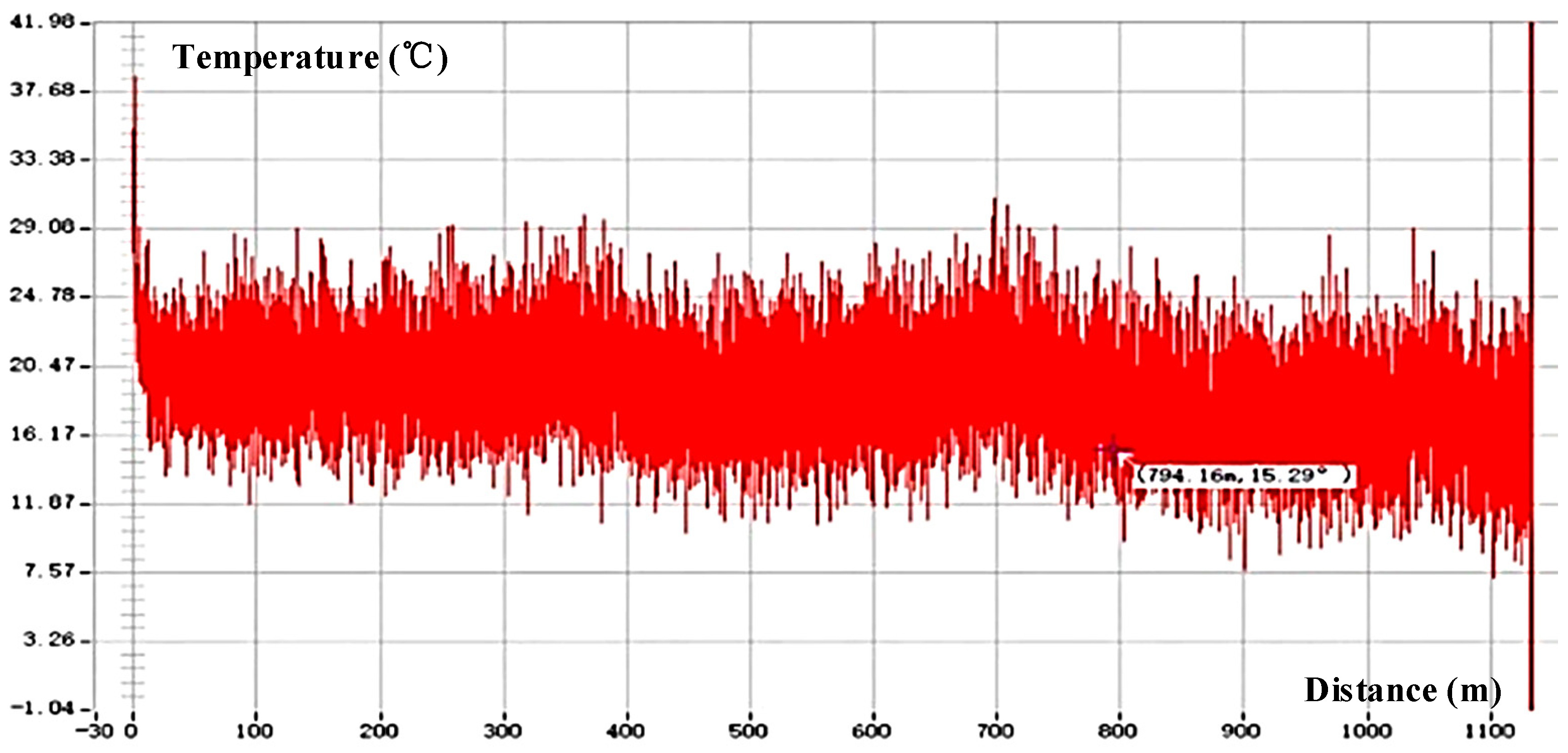
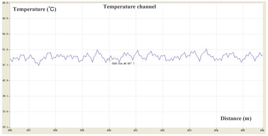
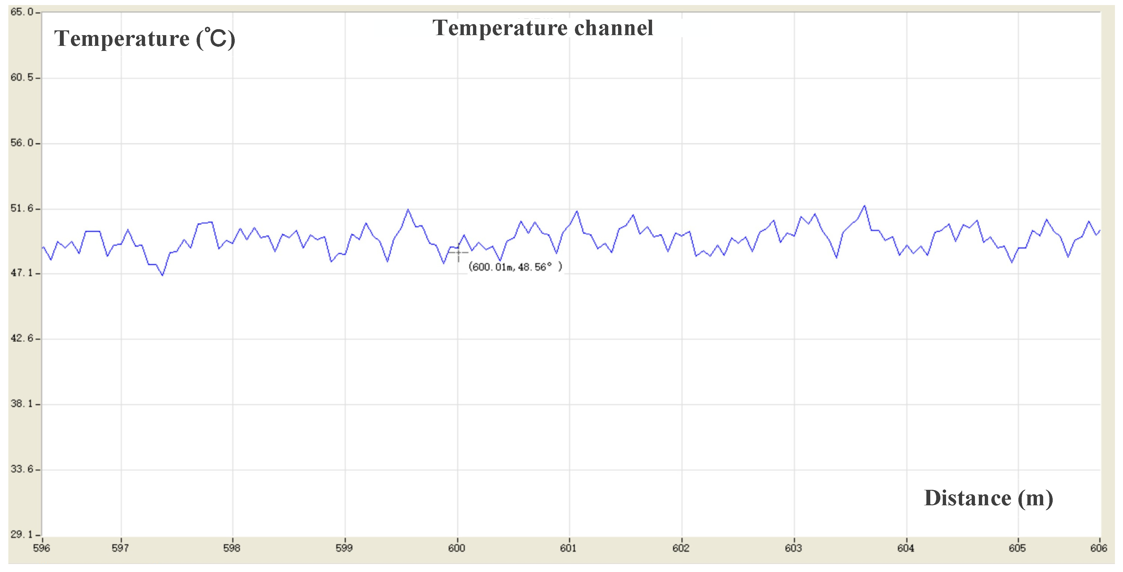
The temperature distribution pattern around the gas storage wellbore was investigated through analysis of distributed temperature sensing (DTS) system data. A multi-mode fiber optic cable was integrated into an additional DTS measurement channel to obtain localized temperature variations, as presented in Figure 11. At a depth of 600 m below the wellbore, the DTS system recorded a temperature of 48.56 °C with a standard deviation of ±0.15 °C across the 24 h monitoring period. This measurement precision falls within the manufacturer’s specified long-term stability tolerance of ±0.3 °C for the DTS instrumentation. The observed minor temperature oscillations near this measurement point are attributed to insufficient post-processing optimization of the DTS signal interpretation algorithm applied to the downhole cable deployment section.
Figure 11.
Temperature change curve in local area (600.01 m, 48.56 °C) of the monitored DTS temperature data along with the cable.
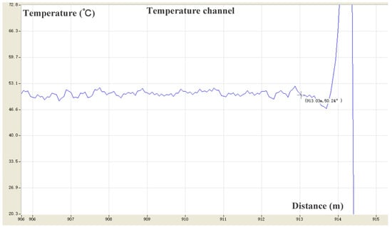
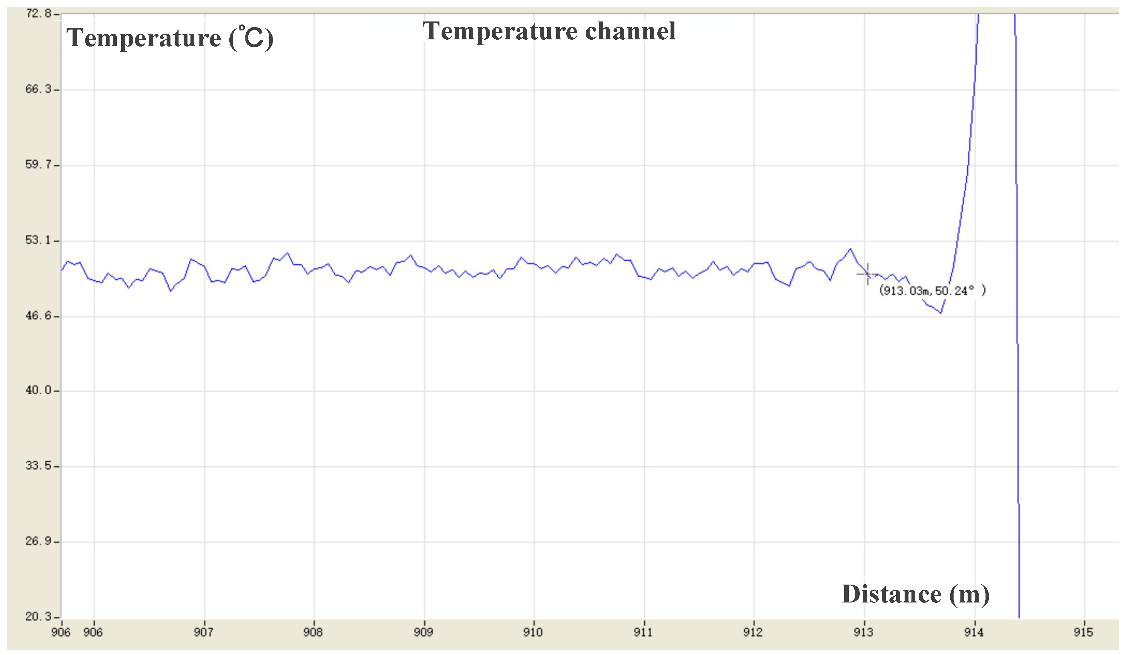
The temperature measurement at the distal terminus of the wellbore cable obtained through distributed temperature sensing (DTS) is subject to optical fiber end-signal interference, which leads to significant fluctuations in the terminal temperature profile and corresponding measurement inaccuracies, as demonstrated in Figure 12. Temperature readings within the final 5 m of the fiber optic cable (908–913 m depth interval) exhibited a standard deviation of ±0.8 °C—substantially greater than those observed in intermediate sections. However, these errors can be mitigated through implementation of advanced terminal signal processing algorithms. While data from the last 10 m of the sensing fiber are excluded from quantitative leakage analyses due to amplified end-effect noise, this segment remains under continuous monitoring for gross thermal anomalies. For instance, the DTS system recorded a temperature of 50.24 °C at the 913 m mark along the cable, which corresponds to the bottom-hole temperature measurement shown in Figure 12.
Figure 12.
Temperature change curve at the bottom of the cable (913 m, 50.24 °C) and the end-effect noise obtained by the DTS system in the wellbore.
Based on the aforementioned DTS testing results and analysis conducted at the newly constructed wellbore (No. XX), it can be demonstrated that the wellbore maintains structural integrity without detectable gas leakage prior to gas injection operations. These findings validate the applicability of this technology for continuous monitoring of wellbore leakage and integrity degradation in salt cavern gas storage facilities.
5.2. DAS Testing Results and Analysis
The acoustic vibrations can be monitored by using the DAS system during the wellbore leakage monitoring and integrity process. The single mode fiber inside the cable is carried out simultaneously. When the optical fiber is affected by external sound waves or deformation, the optical signal will change phase shift. Thus, the DAS system, by detecting the phase shift in the optical signal, may be able to detect the impact of incoming noise and acoustic vibrations around the well site as well as the influence of acoustic vibration after the integrity of the wellbore has been damaged.
The influence of ground noise on monitoring the wellbore structure must be considered. When employing the DAS system for monitoring wellbore leakage and cable integrity, numerous interference and noise sources exist, including generator-induced vibrations from the surface computer room, crane hoisting operations, and acoustic disturbances generated by construction personnel activities such as equipment handling and physical impacts. These factors contribute to both internal wellbore acoustic vibrations and external noise/vibration interference. Consequently, the acoustic vibration signals monitored by the DAS system contain multiple interference noise components. Excessive external acoustic interference can significantly compromise distributed optical fiber acoustic monitoring results. High-intensity external sound waves may obscure authentic acoustic signals, making precise acoustic source localization challenging. Strong ambient noise can also generate spurious alarms by being misinterpreted as abnormal events, thereby increasing false positive rates. Furthermore, phase shifts induced by external acoustic interference become intermingled with genuine signal components, complicating subsequent signal processing analysis. Therefore, implementing noise mitigation strategies during system design and signal processing stages is essential to enhance the system’s capability in rejecting external interference.
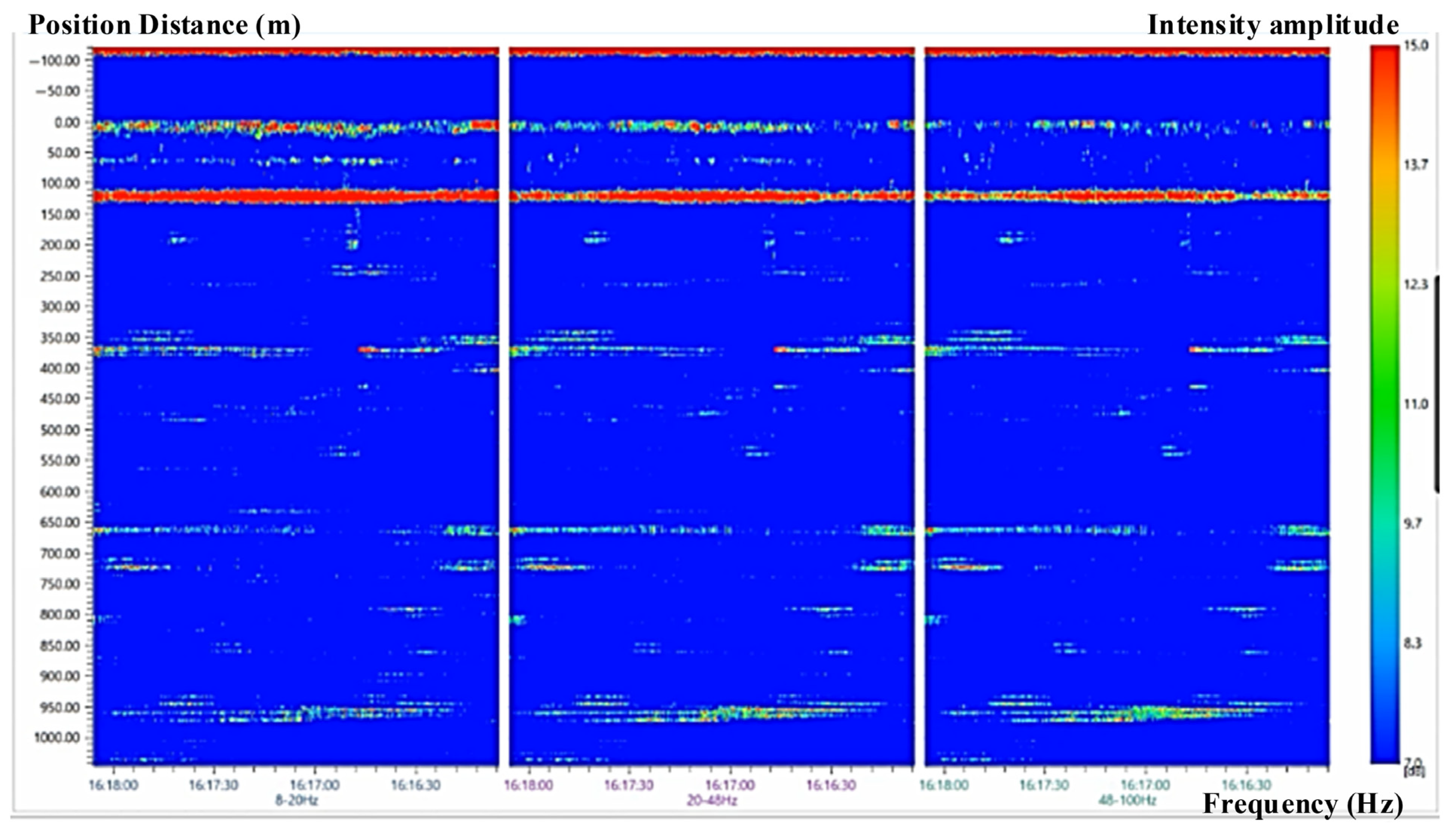
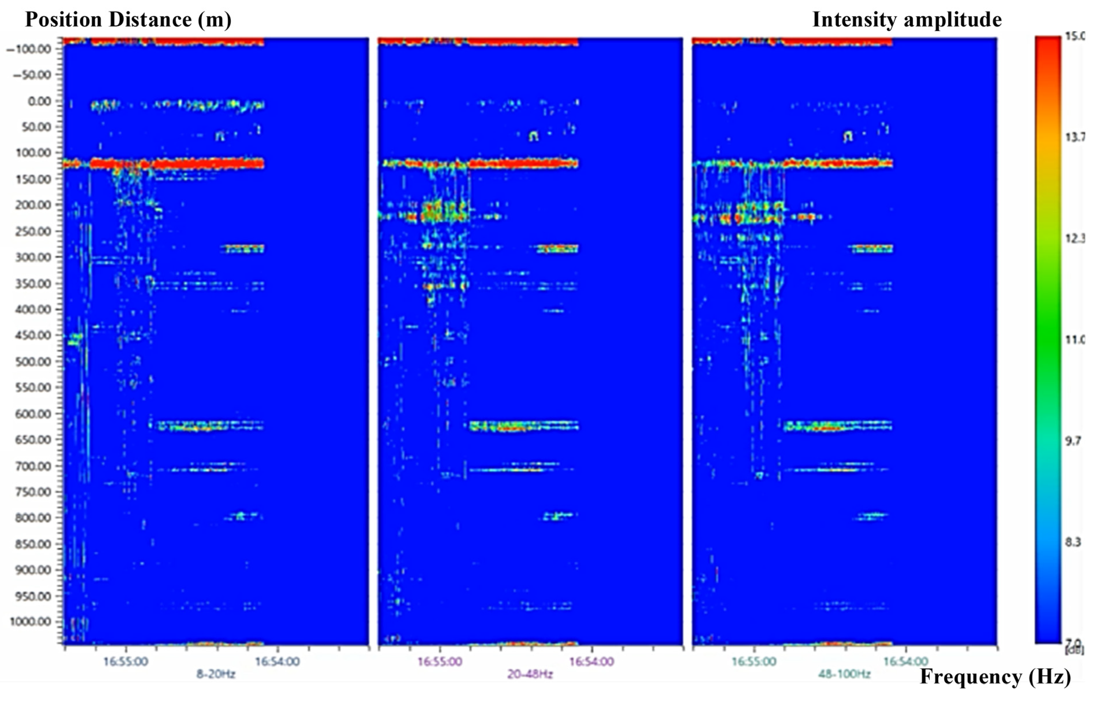
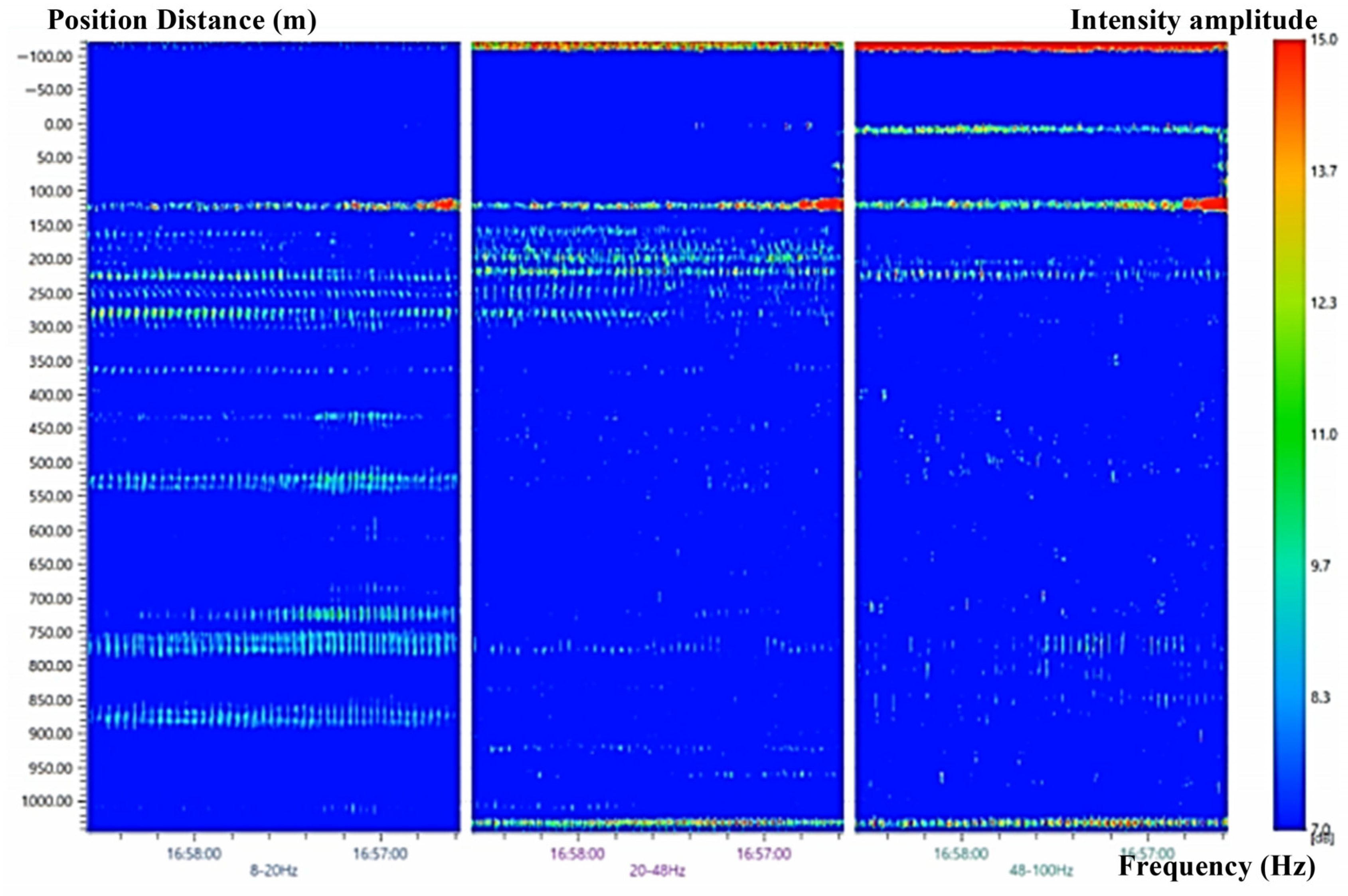
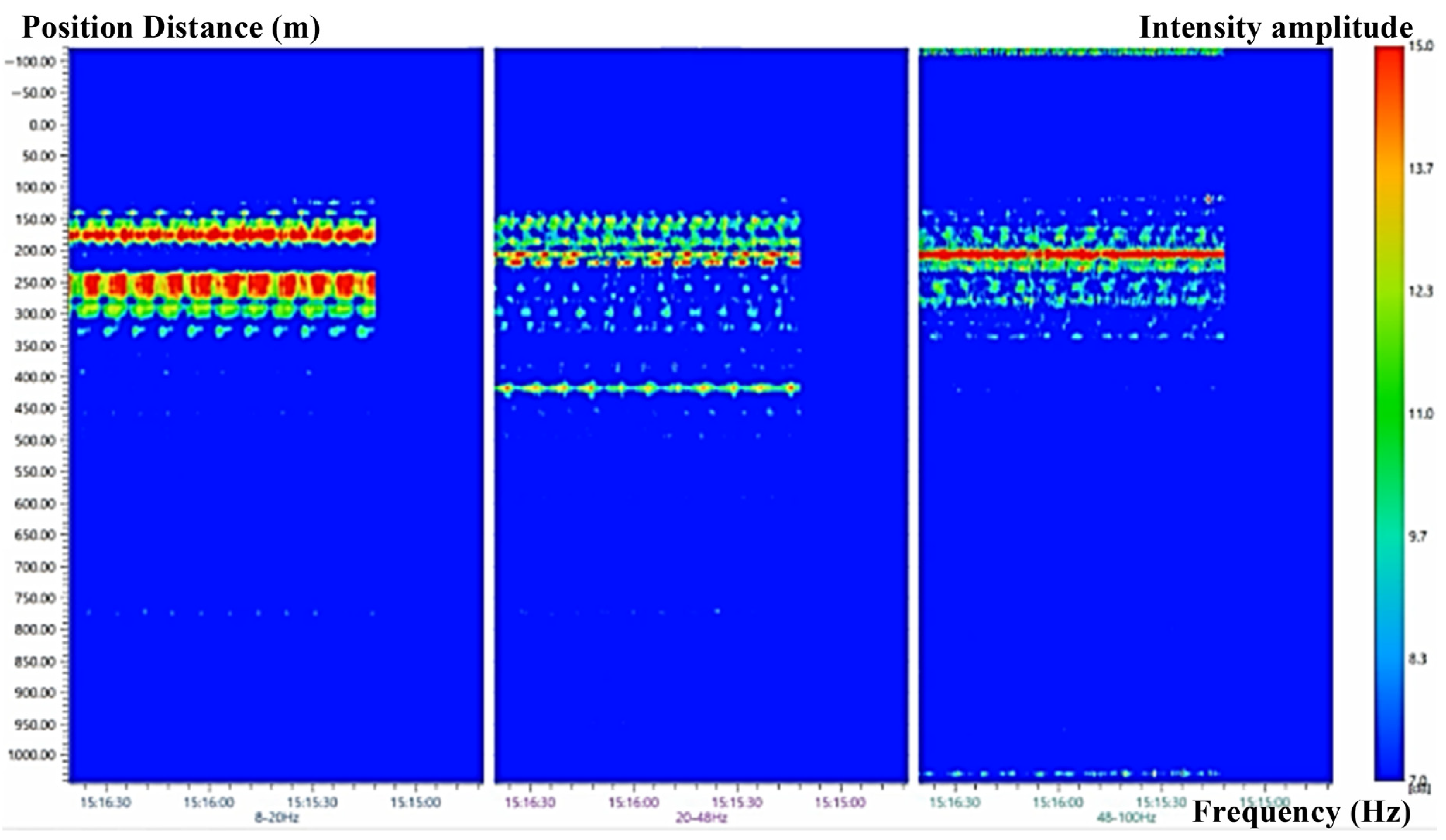
This study focuses on monitoring the acoustic signals around the wellbore during the process of annulus halogenation of the salt cavern gas storage. The monitoring data obtained by using the DAS system is analyzed to determine whether there are abnormal leakage points of the wellbore and to complete the integrity analysis of wellbore cable. Some figures are shown in Figure 13, Figure 14, Figure 15 and Figure 16, which are the analysis result of the interference noise signal detected by the DAS system.
Figure 13.
The acoustic vibration effect of the wellbore monitored by the DAS system before annulus halogenation process.
Figure 14.
An acoustic vibration effect of the wellbore monitored by the DAS system after 10 min of the annulus halogenation process.
Figure 15.
An acoustic vibration effect of the wellbore monitored by the DAS system after the annulus halogenation process is completed.
Figure 16.
Frequency band energy spectrum analysis of acoustic vibration data at a depth of 250 m obtained by the DAS system.
As observed in Figure 13, acoustic vibrations detected by the DAS system primarily originated from mechanical noise generated by the ground machine room and crane hoisting operations conducted without annulus halogenation. Significant interference noise signals propagated through the exposed sections of the multi-mode fiber within the wellhead cable at approximately 120 m depth. Initial data processing identified several discrete points (e.g., at approximately 380 m and 670 m depth) as potential anomalies. Subsequent analysis, incorporating cross-referencing with DTS thermal data (which revealed no corresponding thermal irregularities) and technical review of installation logs, determined these features to be system artifacts caused by localized fiber micro-bending or splice points. This underscores the critical importance of implementing multi-source data validation protocols. Additional noise ingress occurred via steel sleeve connections at cable depths of approximately 380 m, 670 m, and 980 m. During automated signal processing within the DAS system, these interference signals at 380 m, 670 m, and 980 m depths were misinterpreted as valid signal sources due to the system’s inherent high SNR optimization algorithms. These artifacts were erroneously amplified and optimized during signal enhancement procedures. Concurrently, the DAS system’s embedded algorithms identified remaining locations as interference sources, automatically applying noise suppression and filtering optimization to generate the waterfall diagrams presented in Figure 13, Figure 14, Figure 15 and Figure 16.
Figure 14 and Figure 15 show DAS monitoring signals during the injection and halogenation of the annulus inside the wellbore casing. Among them, Figure 14 is the acoustic signal effect diagram around the underground wellbore after 10 min of fluid injection and halogenation in the annulus of the casing. Figure 15 is the acoustic signal effect diagram of the wellbore after the annulus injection and halogen drainage in the casing is basically completed. In addition, the DAS system can also perform band energy spectrum analysis for depth locations, and perform targeted acoustic vibration signal frequency band and energy analysis for a location monitored by DAS equipment, as shown in Figure 16. Figure 16 shows the frequency band energy spectrum analysis diagram of DAS monitoring signals at a depth of 250 m. Through the analysis of Figure 13, Figure 14, Figure 15 and Figure 16 and the entire monitoring process, it can be seen that the DAS device can obtain the distribution of acoustic vibration signals along the wellbore cable. The DAS real-time monitoring results are consistent with those obtained in a relatively quiet and closed environment.
After careful analysis, some acoustic vibrations from surface vehicle vibration and human construction propagate along the casing wall in some areas of the cable because of the impact of some percussion sound waves on the surface and wellhead of the well site during the downhole operation. These acoustic vibrations produce large interfering acoustic signals in the close contact between the armored cable and the casing wall. These signals have a certain degree of signal strength change with the size of the sound of the ground construction operation. The signal strength characteristics were basically in accord with the actual situation of well site surface construction. In addition, the regular “beep” sound in the water injection and halogen drainage process at a tight joint of the casing string in the wellbore was also restored. Therefore, it is verified that the DAS system can monitor the acoustic vibration around the wellbore of the salt cavern gas storage, and the real-time monitoring results of the DAS system also verify that the integrity of the wellbore of the gas storage was not damaged.
The potential factors influencing long-term stability encompass various drift sources, including: (1) DTS Drift, primarily originating from laser source power fluctuations and temporal variations in detector sensitivity; (2) DAS Drift, associated with laser frequency shifts, environmental noise floor alterations, and mechanical stress exerted on the optical fiber; and (3) Environmental Effects, manifesting through temperature cycling of surface and downhole electronic components, as well as pressure-induced micro-bending effects in the fiber. To address these challenges, we implemented multifaceted design and operational strategies: (1) Hardware Design featured temperature-stabilized laser sources and detectors, combined with armored cabling engineered to minimize stress transfer to the sensing fiber; (2) Calibration Protocol incorporated periodic (e.g., monthly) in situ calibration procedures utilizing built-in fiber reference sections maintained at known, stable thermal conditions; and (3) Data Processing employed sophisticated signal processing methodologies, including dynamic baseline subtraction and trend analysis algorithms, to effectively differentiate long-term drift characteristics from genuine leakage signals. Establishment of a well-defined, stable baseline during initial system commissioning represents the fundamental prerequisite for successful drift mitigation. It is acknowledged that the presented 72 h observational dataset cannot conclusively demonstrate multi-year stability performance, necessitating continued long-term monitoring as part of our ongoing research program.
6. Conclusions
This study introduces an integrated framework for wellbore leakage monitoring and integrity assessment tailored specifically for salt cavern gas storage facilities, leveraging the complementary advantages of DTS and DAS devices. The core technological advancement involves an armored photoelectric composite cable engineered to transmit both optical sensing signals and electrical data while withstanding the extreme high-pressure and corrosive conditions inherent to downhole salt cavern environments. When integrated with a permanent downhole pressure gauge, this cable establishes a real-time multi-parameter monitoring system capable of simultaneously capturing temperature profiles, acoustic vibrations, and pressure dynamics along the wellbore—thereby effectively overcoming the constraints associated with conventional single-parameter monitoring approaches documented in prior research.
Field validation was conducted at Well No. XX (Jiangsu, China), a representative operational salt cavern gas storage facility, to assess system performance under actual operating conditions. DTS measurements revealed that the axial temperature profile along the wellbore closely aligned with the regional geothermal gradient, exhibiting deviations less than 2% between measured values at the wellhead, bottom hole, and critical intervals compared to direct in situ readings. The absence of abrupt thermal anomalies—characteristic signatures of gas leakage induced by Joule-Thomson cooling—confirmed no detectable leakage, which was subsequently validated through post-operation mechanical inspection. Concurrent DAS data demonstrated that acoustic signal amplitudes remained within the baseline thresholds expected for sealed systems, with surface-induced vibrations attenuating depth-dependently according to theoretical models of acoustic wave propagation in wellbore fluids. Cross-correlation analysis of integrated DTS-DAS datasets confirmed the system’s capability to identify subtle anomalies at 0.5 m spatial resolution, exceeding the 2 m resolution typical of conventional standalone monitoring systems.
The integrated application of DTS and DAS effectively addresses key technical challenges in monitoring the structural integrity of salt cavern gas storage reservoirs. DTS enables continuous thermal profiling for detecting leakage-induced temperature anomalies, while DAS offers real-time detection capabilities for micro-fracturing events or fluid migration abnormalities through high-fidelity acoustic signal analysis. This synergistic monitoring approach enhances early warning capabilities for wellbore integrity degradation mechanisms, thereby reducing failure risks and ensuring sustained operational safety in underground natural gas storage systems. Future research will prioritize algorithm optimization for automated anomaly identification using machine learning frameworks, alongside implementation of distributed strain measurement techniques to characterize wellbore deformation behavior under cyclic thermo-mechanical loading associated with injection-production operations.
Author Contributions
Conceptualization, X.Z.; Methodology, X.Z.; Software, P.W.; Validation, P.W.; Formal analysis, Z.L. and P.W.; Investigation, Z.L.; Resources, Z.L.; Data curation, Z.L., X.Z. and P.W.; Writing—original draft, X.Z.; Writing—review & editing, X.Z.; Visualization, P.W.; Supervision, X.Z.; Project administration, Z.L.; Funding acquisition, X.Z. All authors have read and agreed to the published version of the manuscript.
Funding
This work was supported by the National Natural Science Foundation of China (No. 42377178), and the Basic Research Project of China Academy of Safety Science and Technology (2024JBKY16).
Data Availability Statement
The original contributions presented in this study are included in the article. Further inquiries can be directed to the corresponding author.
Acknowledgments
All of the images and data are from our actual engineering and are permitted by the owners. We are in compliance with Ethical Standards and all authors declare that this paper has no conflict of interest. Finally, we are grateful for the many helpful and constructive comments from many anonymous reviewers.
Conflicts of Interest
The authors declare no conflicts of interest.
Abbreviations
The following abbreviations are used in this manuscript:
| DAS | Distributed acoustic sensing |
| DTS | Distributed temperature sensing |
References
- Li, H.; Ma, H.; Zhao, K.; Zhu, S.; Yang, K.; Zeng, Z.; Zheng, Z.; Yang, C. Parameter design of the compressed air energy storage salt cavern in highly impure rock salt formations. Energy 2024, 286, 129520. [Google Scholar] [CrossRef] [Scilit]
- Zeng, Z.; Ma, H.; Yang, C.; Zhao, K.; Wang, X.; Zheng, Z. Characterizing imbibition and void structure evolution in damaged rock salt under humidity cycling by low-field NMR. Eng. Geol. 2024, 328, 107371. [Google Scholar] [CrossRef] [Scilit]
- Zou, X.; Wang, T.; Chen, J.; Liao, Y.; Hu, H.; Song, H.; Yang, C. High-precision monitoring and point location optimization method of natural gas micro-leakage in the well site of salt cavern gas storage. Gas Sci. Eng. 2024, 124, 205262. [Google Scholar] [CrossRef] [Scilit]
- Bi, Z.; Wang, L.; Yang, C.; Guo, Y.; Yang, H.; Guo, W. Why acid fracturing is ineffective in carbonate-rich shale reservoirs: From laboratory evidence to field suggestions. Geoenergy Sci. Eng. 2023, 228, 211941. [Google Scholar] [CrossRef] [Scilit]
- Merey, S. Prediction of pressure and temperature changes in the salt caverns of Tuz Golu underground natural gas storage site while withdrawing or injecting natural gas by numerical simulations. Arab. J. Geosci. 2019, 12, 205. [Google Scholar] [CrossRef] [Scilit]
- Chen, X.; Li, Y.; Liu, W.; Ma, H.; Ma, J.; Shi, X.; Yang, C. Study on Sealing Failure of Wellbore in Bedded Salt Cavern Gas Storage. Rock Mech. Rock Eng. 2019, 52, 215–228. [Google Scholar] [CrossRef] [Scilit]
- Adeyemi, T.; Sharma, J.; Tabjula, J. Monitoring and Characterization of Gas Migration in Oil-Based Mud Using Fiber-Optic DAS and DTS. SPE J. 2023, 28, 2802–2816. [Google Scholar] [CrossRef] [Scilit]
- Zhao, K.; Ma, H.; Yang, C.; Chen, X.; Liu, Y.; Liang, X.; Cai, R. Damage Evolution and Deformation of Rock Salt Under Creep-Fatigue Loading. Rock Mech. Rock Eng. 2021, 54, 1985–1997. [Google Scholar] [CrossRef] [Scilit]
- Wolterbeek, T.K.T.; van Noort, R.; Spiers, C.J. Reaction-driven casing expansion: Potential for wellbore leakage mitigation. Acta Geotech. 2018, 13, 341–366. [Google Scholar] [CrossRef] [Scilit]
- Li, D.; Huang, L.; Zheng, Y.; Li, Y.; Wannamaker, P.; Moore, J. Feasibility of source-free DAS logging for next-generation borehole imaging. Sci. Rep. 2022, 12, 11910. [Google Scholar] [CrossRef] [Scilit]
- Huang, Y.; Zhang, Y.; Xie, Y.; Zhang, Y.; Gao, X.; Ma, J. Field test and numerical investigation on deep coaxial borehole heat exchanger based on distributed optical fiber temperature sensor. Energy 2020, 210, 118643. [Google Scholar] [CrossRef] [Scilit]
- Barrias, A.; Casas, J.R.; Villalba, S. A Review of Distributed Optical Fiber Sensors for Civil Engineering Applications. Sensors 2016, 16, 748. [Google Scholar] [CrossRef] [Scilit] [PubMed]
- Chai, Q.; Luo, Y.; Ren, J.; Zhang, J.; Yang, J.; Yuan, L.; Peng, G.-D. Review on fiber-optic sensing in health monitoring of power grids. Opt. Eng. 2019, 58, 072007. [Google Scholar] [CrossRef] [Scilit]
- Lu, P.; Lalam, N.; Badar, M.; Liu, B.; Chorpening, B.T.; Buric, M.P.; Ohodnicki, P.R. Distributed optical fiber sensing: Review and perspective. Appl. Phys. Rev. 2019, 6, 041302. [Google Scholar] [CrossRef] [Scilit]
- Zhou, X.; Wang, F.; Yang, C.; Zhang, Z.; Zhang, Y.; Zhang, X. Hybrid Distributed Optical Fiber Sensor for the Multi-Parameter Measurements. Sensors 2023, 23, 7116. [Google Scholar] [CrossRef] [Scilit]
- Fang, X.; Zeng, Y.; Xiong, F.; Chen, J.; Cheng, F. A review of previous studies on dam leakage based on distributed optical fiber thermal monitoring technology. Sens. Rev. 2021, 41, 350–360. [Google Scholar] [CrossRef] [Scilit]
- Zinsou, R.; Liu, X.; Wang, Y.; Zhang, J.; Wang, Y.; Jin, B. Recent Progress in the Performance Enhancement of Phase-Sensitive OTDR Vibration Sensing Systems. Sensors 2019, 19, 1709. [Google Scholar] [CrossRef] [Scilit]
- Lellouch, A.; Biondi, B.L. Seismic Applications of Downhole DAS. Sensors 2021, 21, 2897. [Google Scholar] [CrossRef] [Scilit]
- Wu, Y.; Gao, L.; Chai, J.; Li, Z.; Ma, C.; Qiu, F.; Yuan, Q.; Zhang, D.; Murayama, H. Overview of Health-Monitoring Technology for Long-Distance Transportation Pipeline and Progress in DAS Technology Application. Sensors 2024, 24, 413. [Google Scholar] [CrossRef] [Scilit]
- Zhu, H.-H.; Liu, W.; Wang, T.; Su, J.-W.; Shi, B. Distributed Acoustic Sensing for Monitoring Linear Infrastructures: Current Status and Trends. Sensors 2022, 22, 7550. [Google Scholar] [CrossRef] [Scilit]
- Tangudu, R.; Sahu, P.K. Review on the Developments and Potential Applications of the Fiber Optic Distributed Temperature Sensing System. IETE Tech. Rev. 2022, 39, 553–567. [Google Scholar] [CrossRef] [Scilit]
- Ashry, I.; Mao, Y.; Wang, B.; Hveding, F.; Bukhamsin, A.; Ng, T.K.; Ooi, B.S. A Review of Distributed Fiber-Optic Sensing in the Oil and Gas Industry. J. Light. Technol. 2022, 40, 1407–1431. [Google Scholar] [CrossRef] [Scilit]
- Araujo, M.M.; Almeida, O.M.; Barbosa, F.R.; Menezes, A.G.C. Enhancing gas formation theory assessment in power transformers by using decision tree transparency and new guess into decomposition temperatures of insulating mineral oil. Neural Comput. Appl. 2024, 36, 3259–3266. [Google Scholar] [CrossRef] [Scilit]
- Peng, T.; Wan, J.; Liu, W.; Li, J.; Xia, Y.; Yuan, G.; Jurado, M.J.; Fu, P.; He, Y.; Liu, H. Choice of hydrogen energy storage in salt caverns and horizontal cavern construction technology. J. Energy Storage 2023, 60, 106489. [Google Scholar] [CrossRef] [Scilit]
- Mahboob, A.; Kalam, S.; Kamal, M.S.; Hussain, S.M.S.; Solling, T. EOR Perspective of microemulsions: A review. J. Pet. Sci. Eng. 2022, 208, 109312. [Google Scholar] [CrossRef] [Scilit]
- Liu, X.; Wang, Y.; Li, S.; Jiang, X.; Fu, W. The influence of reinjection and hydrogeological parameters on thermal energy storage in brine aquifer. Appl. Energy 2020, 278, 115685. [Google Scholar] [CrossRef] [Scilit]
- Jing, J.; Yang, Y.; Cheng, J.; Ding, Z.; Wang, D.; Jing, X. Analysis of the effect of formation dip angle and injection pressure on the injectivity and migration of CO2 during storage. Energy 2023, 280, 128021. [Google Scholar] [CrossRef] [Scilit]

Disclaimer/Publisher’s Note: The statements, opinions and data contained in all publications are solely those of the individual author(s) and contributor(s) and not of MDPI and/or the editor(s). MDPI and/or the editor(s) disclaim responsibility for any injury to people or property resulting from any ideas, methods, instructions or products referred to in the content. |
© 2026 by the authors. Licensee MDPI, Basel, Switzerland. This article is an open access article distributed under the terms and conditions of the Creative Commons Attribution (CC BY) license.