Article

Influence of Wave Rotor Thermal Decomposition on Alternative Nuclear Rocket Propellant Performance †

Department of Mechanical and Aerospace Engineering, FAMU-FSU College of Engineering, Tallahassee, FL 32310-6046, USA
*
Author to whom correspondence should be addressed.
This paper is an extended version of our paper published in the Proceedings of the 2025 AIAA SciTech Forum, Orlando, FL, USA, 6–10 January 2025, as AIAA-2025-0150.
Energies 2026, 19(17), 4047; https://doi.org/10.3390/en19174047
Submission received: 15 July 2026 / Revised: 19 August 2026 / Accepted: 24 August 2026 / Published: 28 August 2026
(This article belongs to the Special Issue Advances in Nuclear Thermal and Electric Propulsion)

Abstract

The proposed wave rotor enhanced nuclear propulsion (WREN) system is a potential technology candidate for timely and efficient manned missions to Mars. Using Hydrogen (H2), conventional nuclear thermal propulsion (NTP) can attain an I s p of 800–1000 s as it reaches the thermal limits of its solid core reactor material. A four-port wave rotor turbomachine coupled to a closed Brayton cycle can go beyond this limitation, further heating the H2 to attain an I s p of 1400–1500 s. Despite this improvement, liquid H2 currently poses significant storage problems that limit transit performance. This work explores the use of denser propellants that use the full launch mass of a rocket compared to liquid H2. This includes ammonia (NH3), water (H2O), and methane (CH4). Using NERVA-class NTP technology, the I s p of these alternatives is comparable to chemical rockets. The WREN fluid and subsystem cycle was modeled using an object-oriented hardware sizing program equipped with NASA CEA thermochemistry and coupled to an optimization framework. Given a specific set of constraints, a 25-klbf (111.2 kN) class WREN engine produced I s p values of 663.6 s for NH3, 469.6 s for H2O, and 360.1 s for CH4. NH3 and H2O achieved density-impulse values comparable to vacuum-rated hydrolox engines, making them competitive with in-space chemical rockets on a volumetric basis. NH3 provided the strongest overall balance of I s p , storage density, and Δ V favorability compared with H2 NTP, whereas H2O produced a small radiator that enabled a higher thrust-to-weight regime. At a representative Δ V of 12 km/s, the propellant savings of NH3 WREN reduced the combined propellant-tank and radiator launch elements from 27 launches for conventional NH3 NTP to 13 launches, of which only nine were propellant-tank launches.

1. Introduction

1.1. Context

Solid nuclear thermal propulsion (NTP) is identified by NASA as a preferred propulsion method for human missions throughout the solar system. In an NTP engine, a solid fissile fuel embedded in a ceramic or carbide lattice heats pressurized liquid hydrogen (LH2) propellant, which expands through a nozzle to generate thrust [1,2].
The performance advantage of NTP relative to chemical combustion propulsion (CCP) arises primarily from the low molecular weight ( M W ) of its hydrogen exhaust (H2). The ideal rocket specific impulse ( I s p ) is
I s p = 1 g 2 γ ( γ 1 ) R u T c h M W 1 p e x p c h ( γ 1 γ )
where R u is the universal gas constant, γ is the ratio of specific heats, and g is Earth’s gravitational acceleration. I s p is the measure of time, in seconds, in which 1 kg of propellant can produce a force equal to its own weight. The equation provides a qualitative basis for understanding the fundamental performance trade between CCP and NTP. That is, as M W decreases or chamber temperature ( T c h ) increases, the engine becomes more effective at using its onboard propellant to generate thrust. With one of the smallest M W values of any propellant (≤2.016 g/mol), H2 NTP can achieve a much higher I s p ceiling than CCP.
The fundamental contrast between the two systems is that CCP is primarily energy limited, whereas NTP is power limited by the thermal and structural constraints of the reactor. This power limitation more directly constrains the achievable thrust of NTP systems. The highest thrust engine of the US Nuclear Engine for Rocket Vehicle Applications (NERVA) program, the XE Prime, and its USSR counterpart, the RD-0410 of the Chemical Automatics Design Bureau (KBKhA), achieved 55.4 klbf (246.6 kN) and 7 klbf (35.3 kN), respectively [3,4]. NTP, nevertheless, offers additional potential advantages over CCP, including the use of a single working fluid without the need to store a separate oxidizer and the absence of a combustion process, which may simplify propellant management and facilitate reliable multiple engine restarts. For this work, the primary motivation is to assess the potential propellant-mass savings of different NTP propellants and engine configurations relative to CCP for mission profiles with comparable Δ V requirements.
The SpaceX Raptor engine is capable of up to ∼380 s of I s p using a methalox ( M W of 21–23 g/mol) propellant in a vacuum [5]. The highest I s p CCP engine is the RL-10: a hydrolox ( M W of 10–14 g/mol) engine capable of ∼465.5 s [6]. By contrast, the NERVA program and Soviet RD-0410 NTP engines demonstrated 811–910 s of vacuum I s p using purely H2 propellant [3,4]. More recent system-level concept studies, such as the ESA’s ALUMNI project [7], ISRO’s small nuclear rocket designs [8], and KAIST’s Korea Advanced Nuclear Thermal Engine Rocket (KANUTER) concept [9], reported I s p performance estimates of 865–944.5 s. This doubling of I s p eases the burden of required mass fractions for a given mission profile Δ V, as shown by the ideal rocket equation
Δ V = I s p g ln R ,
with the stage mass fraction
R = m v + m p , t m v + m p , t + m p ,
where m v is the mass of the vehicle, including engine and payload, m p , t is the final mass of the propellant tanks, and m p is the mass of the propellant used during the burn.
Despite its high I s p , LH2 presents significant storage challenges due to its low density. To evaluate performance under volume constraints, the density-impulse metric ( I ρ ) is defined as the product of propellant storage density and respective engine I s p [10]. A higher I ρ indicates greater total impulse for a given tank volume. Table 1 lists storage densities for several candidate NTP alternative propellants and other liquids.
Based on Table 1, NERVA NTP has an I ρ of ∼ 63.7 × 10 3   kg · s m 3 . For comparison, the RL-10 Hydrolox and Raptor Methalox have an I ρ of approximately 450 × 10 3 and 370 × 10 3   kg · s m 3 , respectively. It can be assumed then that CCP is potentially more advantageous to NTP based on packaging constraint. This was one of the motivations for the development of the now canceled SLS Block II cargo shroud to alleviate the volume constraint of launching LH2 to orbit and enable a more favorable mass fraction.
Table 1 also includes the approximate I s p required to match the I ρ of the RL-10 and Raptor engines. Compared to LH2, the other candidate NTP propellant I s p are far less demanding for equivalent packaging performance to CCP. However, the temperatures required to achieve these I s p values exceed the material limits of solid-core NTP fuel elements [11,12], where structural materials experience an unacceptable loss of strength. This work demonstrates how wave rotor technology could enable an unsteady energy-exchange process that circumvents reactor core material limitations, making alternative NTP propellant systems (NTP-A) a viable and cost-effective architecture for a cislunar tug or Mars transit vehicle.

1.2. Propellant Limitations and Alternatives

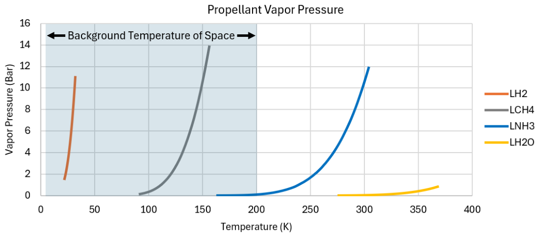
LH2 is a “hard” cryogen that is one of the most difficult propellants to store long-term. In order to reach its maximum liquid density of 70.8 kg/m3 at 1–2 bar, LH2 must be maintained at or below 25 K. It is an inherent issue of leakage [13] and vapor pressure curve [14], shown in Figure 1, that prevents the use of higher pressure storage which may circumvent temperature requirements. Due to it is low density, LH2 can be volume limited depending on the launch vehicle. In the case of the SLS Block 2 Cargo system, the large shroud mitigates this issue by accommodating a 988 m3 payload volume for a >46 t payload to trans-lunar injection (TLI). Commercial vehicles, on the other hand, tend to have much smaller fairings, limiting the volume of LH2 that can be sent to orbit.
In practicality, tank size must conform to the aspect ratio of the available launch vehicle fairing size to maximize packing density. The mass penalties of a cylindrical tank of an aspect ratio of 2:1 compared to a spherical tank of equivalent volume increase by 20% based on geometry alone [15]. Additionally, the increased surface area necessitates more insulation and thermo-optical cabling to attain reduced boil-off (RBO) of the LH2, further exacerbating mass penalty and volume limitations.
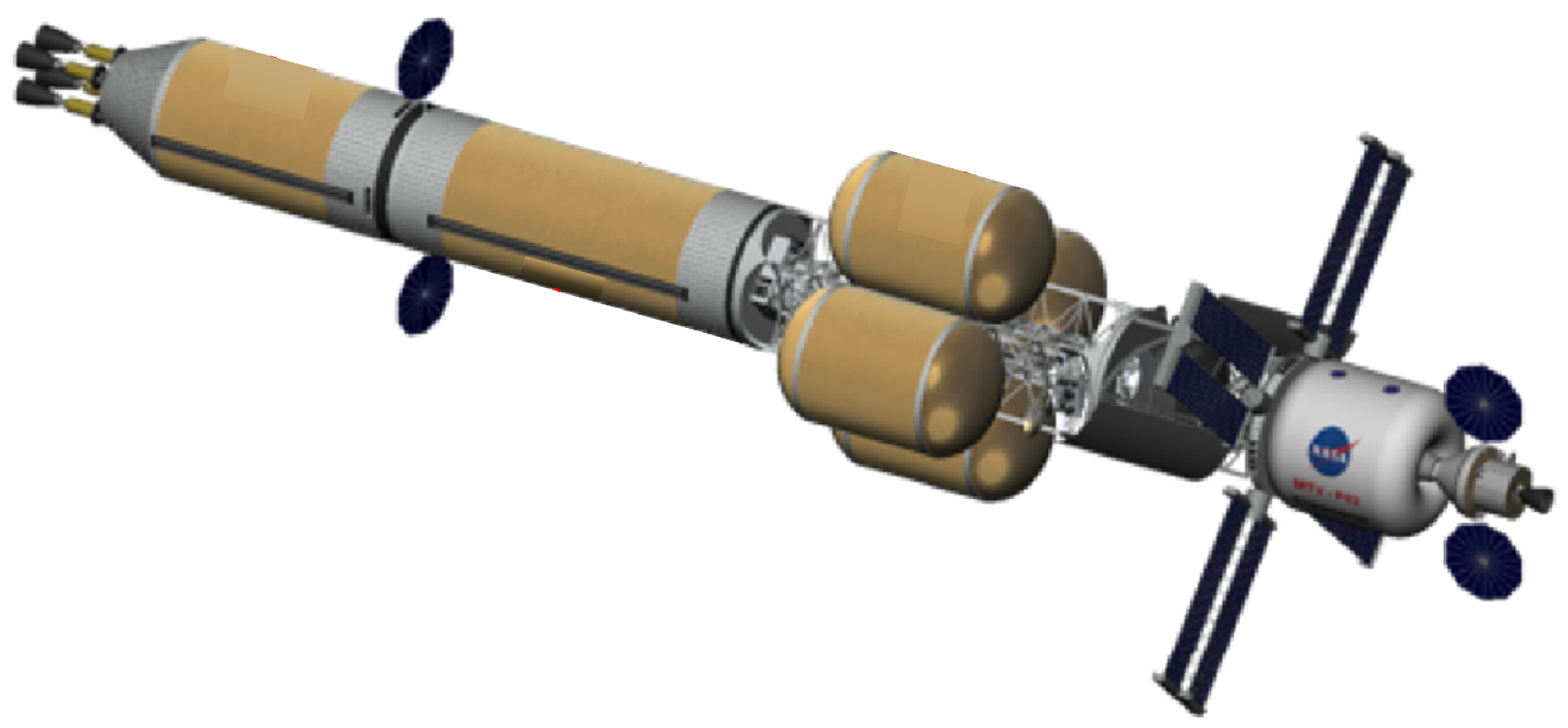
Unless given excessive insulation through foam or complex and heavy annular cryogenic fluid jackets, gaseous LH2 must be continuously vented [16,17]. Zero boil-off (ZBO) tanking has been demonstrated to store large quantities of LH2 with zero loss for durations ≥13 months, but mass fractions and other system-level penalties become mission-limiting, especially for shorter loiter times [17,18]. RBO NTP vehicles are the best in terms of maximized mass fractions [15] but are impractical for long mission times. Current RBO cryostat technology designs are intended to store LH2 for a few weeks. Consequently, proposed NTP Mars architectures often require on-orbit construction of numerous propellant drop tanks and extensive launch campaigns to account for propellant losses and to optimize stage mass fractions. Figure 2 is a conceived Mars vehicle architecture with a multitude of RBO drop tanks and inline (mission permanent) ZBO tanks, requiring no less than 8 HLV/SLS launches for construction and refueling operations [19]. This particular system is intended for a 3-year conjunction-class mission with a 100-day transit to and from Mars and a required Mars surface stay time of roughly 660 days. A faster alternative proposed by Aerojet Rocketdyne is a 2-year opposition-class mission with a surface stay of ∼30 days but would require on the order of 4 SLS and 16 HLV launches [20]. Reducing this time as much as possible while enabling reasonable surface-stay times is in the interest of manned missions, as it minimizes risks that could jeopardize astronaut safety and mission success.
To assemble the spacecraft, repeated transits within cislunar space may require flexibility, where the immediate need of a lunar tug will limit the time frame of orbital refueling. Thereby ZBO becomes cost-effective in limiting launch number and is open to rapid CONOPS. For these reasons there has been a large investment into the research of LH2 ZBO [18]. This work is then motivated to explore other alternative propellants that may be easier to use for long-duration missions.
Higher-density liquids including water (LH2O), ammonia (LNH3), and methane (LCH4) have been identified as high-potential NTP-A propellant candidates [12,15]. With storage densities of approximately 1000 kg/m3 (277 K), 680 kg/m3 (239.8 K), and 423 kg/m3 (111.7 K) at 1 atm (1.01325 bar), respectively, these fluids reduce volume and insulation requirements. This leads to potentially better vehicle mass fractions and lower tank launch count for specific Δ V regimes. Moreover, storage technologies for these liquids are mature or less demanding. For example, ammonia may achieve passive ZBO using high-reflectivity coatings [15], and long-duration methane storage has already been demonstrated by SpaceX [21]. Water requires only modest pressures to remain liquid at temperatures above the background of space, suggesting potential dual-use as a thermal heat sink.
These propellants are also compatible with in situ resource utilization (ISRU) strategies emphasized by the Artemis program [22,23,24]. Near-term architectures; however, primarily focus on minimizing launch mass to low Earth orbit (LEO) before ISRU becomes operational. Thus the scope of this research only extends to tank launches to LEO which can utilize a space-tug delivery system to various orbits. This allows the stage propellant mass fraction to be maximized and the NTP/NTP-A vehicle to be fully fueled for an injection burn.
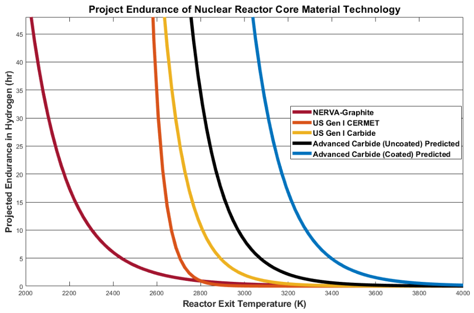
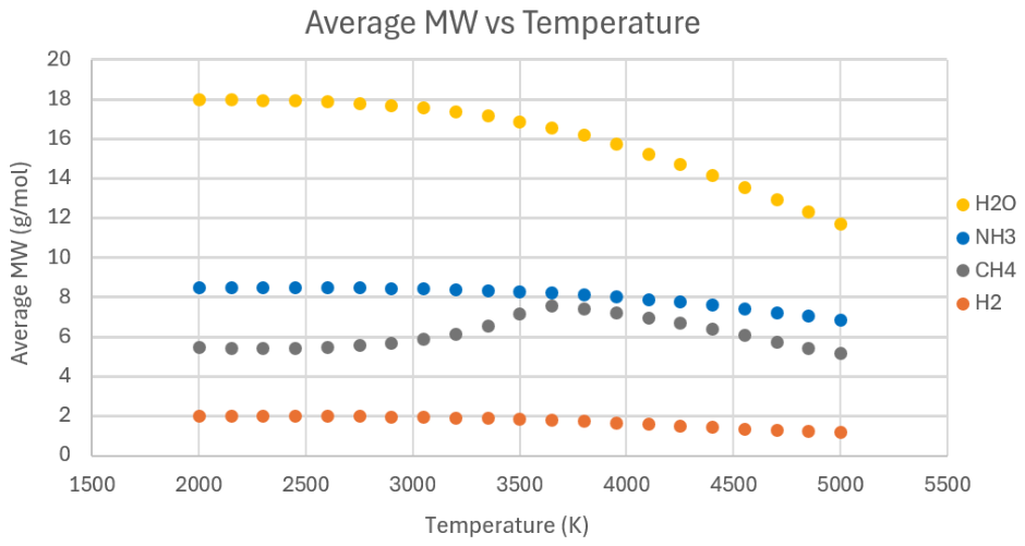
Despite these advantages, the performance of these heavy NTP-A propellants is limited by the maximum operating temperature (MOT) of the fuel elements. For reference, Figure 3 shows the projected NTP core endurance versus the exit temperature of H2 [25]. Using the NASA Chemical Equilibrium with Applications (CEA) program [26,27], Figure 4 presents the average M W of propellants as a function of temperature at their corresponding critical pressures. The purpose of this pressure convention is to demonstrate how the NTP-A propellant M W compares within a physical reactor, which requires the propellant to be at a critical state, at a minimum, during core heating. Note that a pronounced reduction in M W occurs above approximately 3000 K, indicating increased hydrogen species concentrations above long-endurance MOT of existing solid NTP core materials.
Under NERVA conditions of 2400–2850 K and at critical pressure, ammonia NTP-A can theoretically achieve ∼450 s I s p [12], assuming the ideal Equation (2) with no losses. This is comparable to hydrolox CCP but still half of hydrogen NTP. Nevertheless, its resultant I ρ is 306 , 000   kg · s m 3 , roughly five times that of LH2. Whether this implies a larger payload capacity or range depends on the mass fraction favored by Equation (2).
Because high I s p remains the dominant factor for maximizing Δ V , hydrogen still offers the highest performance ceiling. Overcoming reactor MOT limits is therefore essential for enabling competitive NTP-A systems.

1.3. Solutions to Challenges

One solution to the power limitations of NTP-A is a liquid- or gas-phase nuclear core [28,29,30,31,32]. These engines allow their fuel to change state to enable exceptionally high temperatures, up to ∼5200 K for liquid and >10,000 K for gas cores. A liquid-phase core has been suggested by Houts et al. [29] to enable the use of any passively storable volatile, with a performance of 700–900 s I s p for propellants heavier than H2 [30]. However, material and fuel element containment still requires significant maturation as a fully integrated system. To mitigate fuel erosion, one proposed concept is the Centrifugal Nuclear Thermal Rocket (CNTR) [29,31], in which the fuel elements are rotated at high speed using turbines that are turned by the propellant flowing from the nozzle regenerative cooling cycle. The centrifugal force generated can hold the liquid fissile material to the walls while bubbles of propellant are pumped through it, heated, and subsequently exhausted for high efficiency burns. Apart from the low technological maturity compared with solid core reactors, the rate at which extremely high M w reactor fuel is vaporized will cause efficiency to drop at high power. Work by Santana and Hollingsworth [33] estimated an upper limit of 1400 s for liquid-phase-core I s p using H 2 at a chamber temperature and pressure of 4500 K and 100 atm (101.2 bar). Beyond this temperature or below this pressure, the reactor fuel material is entrained in the flow at significant concentrations. Above this pressure and the H 2 dissociation rate diminishes.
The present authors explore the use of wave rotor (WR) technology to facilitate the superheating of a propellant by an unsteady, shock-driven energy exchange with a closed Brayton cycle (CBC) [25,34]. The wave rotor enhanced nuclear (WREN) propulsion concept, which has been further developed in [35,36], integrates a WR between the NTP reactor core outlet and the nozzle inlet. This configuration enables propellant superheating outside the core, thereby circumventing MOT constraints inherent to the reactor. A CBC, analogous to architectures proposed for Prometheus systems, supplies the required compression work via a high-sound-speed driver fluid. Assuming a full hydrogen WREN cycle, where both the propellant and CBC driver fluids are H2, results indicate that the I s p of conventional solid-core NTP systems could be boosted by approximately 50–60% at NERVA-class thrust with the addition of large radiators for power generation.
Historical experiments and propulsion studies support this capability of compressive heating. For example, the Cornell Aeronautical Laboratory “Wave Superheater” was a 2 m wide WR device capable of producing compressed air as high as 4000 K and 120 bar, starting from ambient [37,38]. The Superheater featured a nozzle extension following the compressed gas exit port for flow exhaustion to a test chamber to emulate hypersonic conditions [38], demonstrating its potential rocket-like application. This potential was first noted by Squire and Saad in the early 1960s [39,40]. For in-space propulsion, they considered a Rankine cycle using steam for the driver in order to provide a low cycle bottom temperature. To the author’s knowledge, this is the only instance where a WR was considered in this application. Unfortunately, Squire and Saad’s method was found to be relatively ineffective at increasing H2  I s p despite greater system complexity, owing to the low sound speed of the driver relative to that of the compressed gas, with a maximum I s p of ∼1000 s [39]. In order for the Wave Superheater to attain such effective compression, the system used hot helium as the low M W driver gas to attain the desired sound speeds [38].
CBC power generation in spaceflight is limited by the power cycle’s ability to reject waste heat generated by its energy conversion process. NASA’s Prometheus program had determined that a nuclear electric propulsion (NEP) spacecraft should use a helium, helium-xenon, or other high sound-speed working fluid within a CBC in order to minimize the radiator area [41,42,43]. This is a coincidental overlap noted by the authors’ past work [34,35,36], where WR compression and Brayton-based NEP architecture may enable improved NTP performance.
A major component of the WRs’ benefit is not only the ability to heat a flow via shock-driven compression but also the ability to decompose a fluid into its constituent particles to a greater extent than thermal equilibrium alone, known aptly as “cracking” in an unsteady process [44]. These considerations motivate the use of the WREN architecture proposed by Gosse et al. [34] as a pathway for high-performance NTP-A systems using high-TRL components and more practical propellant storage strategies. In this framework, WREN offers the potential to achieve I s p equivalent to or exceeding those of traditional CCP while simultaneously alleviating NTP requirements of high in-orbit tank delivery count and poor mass fractions. From an I ρ perspective, however, competitiveness with the CCP requires that the WREN system attain the target I s p values for each candidate propellant listed in Table 1. Consequently, this work seeks to quantify the extent to which WR-driven heating can enable these performance thresholds, thereby assessing the viability of WREN-enabled NTP-A architectures for future in-space propulsion applications.

1.4. Work Overview

This article is a revised and expanded version of a conference paper entitled “Propellant Alternatives of Nuclear Thermal Propulsion using Wave Rotor Pressure Exchanges”, which was published in the Proceedings of the 2025 AIAA SciTech Forum, Orlando, FL, USA, 6–10 January 2025, as AIAA-2025-0150 [36].
The present study incorporates corrections to the constraints and operation of the system, which were ignored in the previous work. This includes: (i) NTP-A propellants are held at or above supercritical state during heating; (ii) WREN H2 cycle uses an H2 driver gas (identical configuration to Gosse et al. [34]), while the other NTP-A propellants use a helium (He) driver in the CBC; (iii) the propellant turbopump receives power from the main CBC drive shaft rather than assuming losses via a bleed cycle configuration [1]; and (iv) the heat exchanger (recuperator) model, which provides some additional cooling to the CBC to enable reduced radiator sizing, has been updated to align with current in-space heat exchanger technology [45].
No particular trajectories or burn times are analyzed in this work. Instead, general analyses of comparative performance and implications of the WREN NTP-A propellants are addressed. Many of the same parametric and sensitivity studies previously disseminated during the conference proceedings [36] are included and updated here. This includes baseline design performance estimates in Section 3.1, sensitivity to thrust, I s p , and core temperatures in Section 3.2, and trade analysis in fuel savings to required launcher campaigns followed by Δ V favorability compared with other architectures in Section 3.3. A new optimization framework to the zero-dimensional systems-level performance model has been developed to broaden the search of feasible designs and is described in Section 2.3. Additionally, the potential for WREN to enable the more challenging propellants is explored in more detail in Section 2.5.1.

2. Materials and Methods

2.1. Wave Rotor Technology

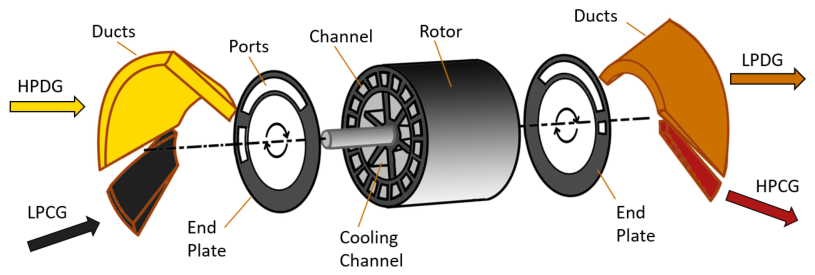
The wave rotor (WR), or dynamic pressure exchanger, is a turbomachinery device that transfers energy between fluids through shock waves and expansion fans. WRs have been applied in combustion systems, refrigeration cycles, and high-enthalpy test gas generation [37]. A four-port, through-flow WR, illustrated in Figure 5, consists of an array of equally sized axisymmetric channels that rotate about a central, motorized drum within a housing. This rotation periodically exposes the channels to ducted pressure reservoir ports, enabling controlled sequences of shocks and expansions.
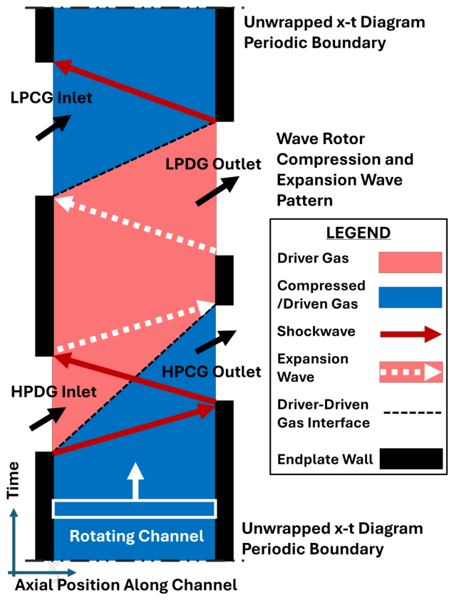
The associated wave pattern for compression and expansion processes is shown in Figure 6. When high-pressure driver gas (HPDG) enters a channel, it initiates a compression shock that raises the pressure and temperature of the low-pressure compressed gas (LPCG). The reflected hammer shock further increases the state to a high-pressure compressed gas (HPCG) prior to exhaustion. Subsequent expansion waves remove the driver gas and reset the channel for the next cycle. The outflow of HPCG and the now low pressure driver gas (LPDG) is homogeneous through the correct timing of port openings and wave reflection.
The WR has been studied at length in the context of jet Brayton cycles, where the WR receives LPCG from the compressor and HPDG from the combustion chamber; this generates HPCG to extract more power from the combustion chamber and expands the HPDG to LPDG where it is below or at the MOT of a turbine upon exhaustion. This process has been shown by the likes of Paxson [46], Wilson [47], and Welch [48] to improve the specific power and thermal efficiency of engines. This is due to the high isentropic efficiency afforded by shock-driven wave compressors [37], which increase pressure on the turbine by >20% compared to the compressor outlet [47]. Their research also found that macroscopic balances of volume-averaged thermodynamic properties within the rotor passage control volume provide a simple, system-level method for analyzing performance.
The WR can be configured to operate as a type of compressor by directly exhausting the HPCG. Instead of topping a Brayton cycle, the WR utilizes a separate heated driver flow or closed Brayton cycle (CBC) for a desired compressive heating of a fluid, such as the Wave Superheater [38].
It should be noted that since the WR is an unsteady inertial fluid device, the rapid alternation between hot and cold flows will exist within the channels in approximately equal times and below the heat transfer rate of the channel walls [48]. Therefore, the WR is tolerant to transient peak fluid temperatures and pressures that exceed continuous exposure limits, making it an ideal option for superheating propellants.

2.2. Wave Rotor Topping Cycle

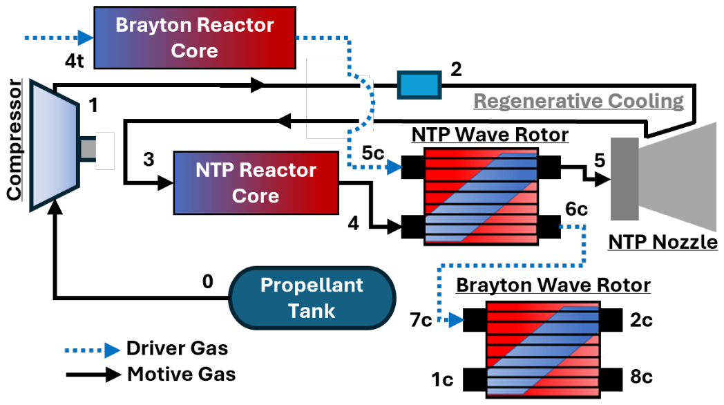
A schematic of the Wave Rotor Enhanced Nuclear (WREN) propulsion concept NTP cycle is shown in Figure 7. Station 4 corresponds to LPCG, station 5 to the HPCG, station 5c to the HPDG, and station 6c to the LPDG. The working (CBC) fluid flowing from stations 5c to 6c (driver gas) provides the energy required to compress the propellant, or motive gas, from stations 4 to 5.
Assuming equal compression and expansion work within the wave rotor control volume, infinitesimally thin channels for continuity, and negligible viscous effects, an ideal characteristic equation can be derived based on the work of Wilson and Paxson [47]. If the compression and expansion processes are further assumed to be polytropic, the pressure ratio from station 4 to station 6c is
P R 4 6 c = P R 5 6 c 1 ( 1 η 5 c 6 c ) η 5 c 6 c η 5 4 T 1 T 6 c P R 5 4 γ 1 γ 1 1 + 1 η 5 4 T 1 T 6 c P R 5 4 γ 1 γ 1 γ γ 1
This quantity is also referred to as the total pressure ratio (TPR), defined as p 6 c / p 4 . The expression is useful for estimating boundary conditions in systems-level modeling. Experimental results indicate that excessively high TPR values reduce confidence in achievable polytropic efficiencies at minimum exhaust gas recirculation (EGR), which provides practical constraints for the macro-model. Work by Tuchler and Copeland [49] identified a maximum TPR of ∼ 1.63 for an isentropic efficiency ( η 4 5 and η 5 c 6 c ) of 80%. EGR is an inherent characteristic of WRs, arising from the incongruity between rotor rotation and diffusion across gas discontinuities, shock-wave propagation speeds, and viscous wall boundary-layer effects [50].
The mass flow rates of the expansion and compression process for Equation (4) are also assumed equal; however, this is not the case for the NTP WR, which couples the NTP and CBC cycles. During a systems analysis, where the temperature and pressure ratios of the ports satisfy Equation (4), the necessary mass flow rates that yield the intended compression ratio of the motive gas can be determined. This is done by calculating the work of the compression process:
W ˙ W R c o m p = m ˙ 4 5 | h 5 h 4 |
where m ˙ 4 5 is given by the intended thrust, and enthalpy (h) is based on the CEA results of the fluid states solved by Equation (4). Since the work of expansion is assumed equivalent to compression, the mass flow rate of the driver gas can be calculated by:
m ˙ 5 c 6 c = W ˙ W R c o m p | h 5 c h 6 c |

2.3. Systems-Level Fluid Equilibrium and Optimization Model

In order to model the system as a whole, an object-oriented program (OOP) algorithm was developed. Each subsystem is modeled as an independent object, allowing the application of different constraints on the propulsion system for robust iteration and optimization. These object classes were established as either inheriting or being composed of other classes. For example, all the engine sub-components that contain some sort of gas flow are given the thermochemical qualities of a “gas class” to determine work processes. Adjacent components were interfaced through shared up- or down-stream values of fluid stations, and thermodynamic properties were calculated using the NASA chemical equilibrium and applications (CEA).
CEA is a thermodynamic database program developed at NASA Glenn that uses ideal gas thermodynamic properties of individual species and minimizes the Gibbs energy of thermodynamic states specified by the user [26,27]. Minimization occurs through the iteration of species quantities using a Newton–Raphson method based on an original guess of molar ratios for the given fluid(s). This program was incorporated into the OOP WREN model through a MATLAB R2024a wrapper module (CEAM 1.3) [51]. Inputs and outputs from system components were processed through a code object that called upon the module while keeping track of the current species and thermodynamic states. These states were saved as individual properties within the objects to track the progression of states throughout the NTP and CBC subsystems.
An optimization framework is introduced, which iterates and refines on input arguments to the OOP framework. This is done through a hybrid global search and local refinement approach, in which an initial population of candidate designs is sampled randomly using Monte-Carlo sampling across the allowable design space. Random sampling was performed using a Mersenne Twister pseudorandom-number generator, with a nominal seed of 1 to ensure reproducibility. The highest-performing candidates are then selected as starting points for local refinement using a Nelder–Mead simplex method [52]. Bounds on the design variables are enforced through a logistic variable transformation, while constraint violations are incorporated into the objective through quadratic penalty terms. This allows the optimizer to explore a broad range of feasible and near-feasible designs before converging toward configurations that satisfy the encoded constraints. Apart from constraint violations, the model scored the systems on a schedule of minimum mass and/or maximum I s p , depending on parametric analysis, and a balanced drive train. For this work, an initial population of 15,000 designs was sampled, of which the top 50 were chosen for refinement.

2.4. Model Assumptions and Constraints

2.4.1. Full Engine Architecture

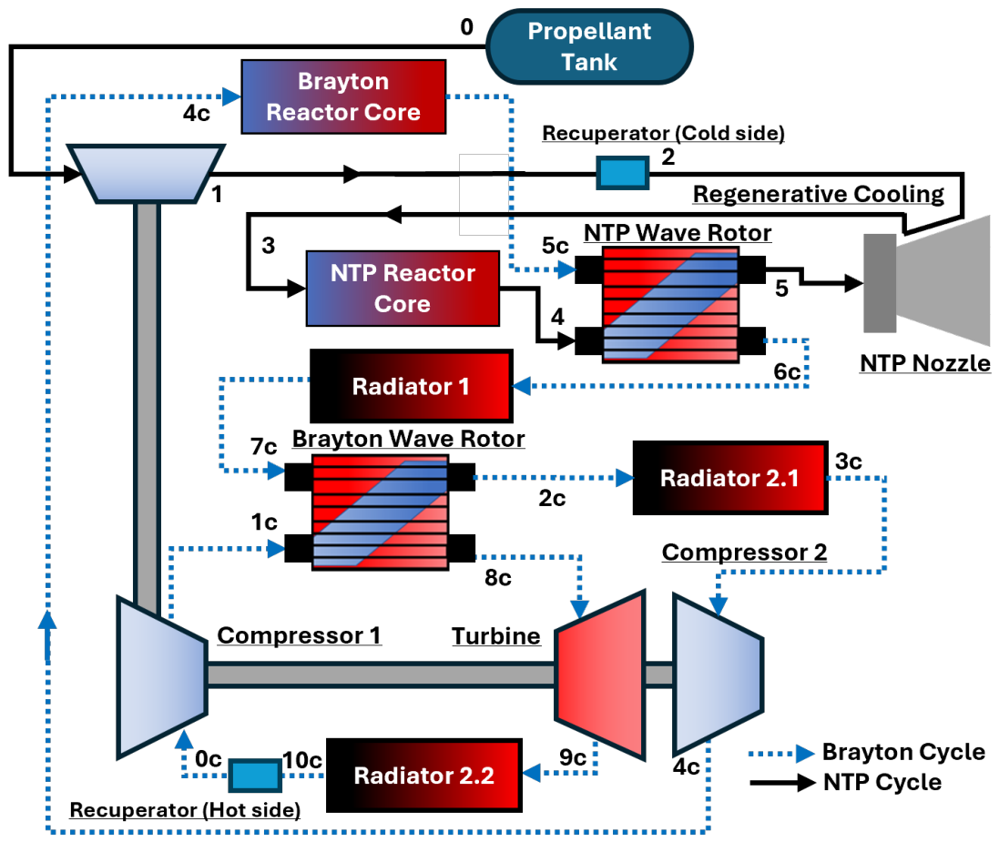
The generalized concept of the full WREN NTP-only system is illustrated in Figure 8. In order to provide the NTP WR with the required supply of pressurized driver gas needed to compress the motive gas, a closed Brayton cycle (CBC) coupled to a second WR was proposed [34]. The Brayton-topping wave rotor (BWR) is intended to both constrain turbomachinery size and improve CBC thermal efficiency. WREN also incorporates large radiators to reject the CBC waste heat. Accordingly, a key objective of this work is to justify radiator sizing by quantifying the extent to which CBC coupling enhances NTP and NTP-A performance.
Through diversion piping of the working fluids and alternator actuation via the drive shaft, the CBC can also provide substantial electrical power for an NEP mode after completion of the NTP burn. This bimodal architecture increases the average mission profile I s p and enables faster translunar trajectories. The novelty of this approach is twofold: (i) CBC power conversion has not previously been considered for NTP superheating through WR coupling, and (ii) both NTP and NEP capabilities are enabled through a shared, localized power-conversion engine. This contrasts with prior hybrid transit concepts such as the NEP-CP Hybrid concept vehicle 1.2 [2], which employs separate, dedicated engines and power systems. This work focuses on the implications of alternative propellants for WREN operating in NTP mode only; therefore, engine sizing estimates exclude NEP-specific hardware.
A conservative design approach for component masses and WR performance is assumed to ensure the system remains feasible under worst-case conditions, avoids performance shortfalls caused by underestimated weight, prevents cascading redesigns, and provides safety margins that can be reduced later as the system becomes better understood. This includes the decision to model two separate solid cores instead of a unified core that heats both the motive and driver gases simultaneously. The second Brayton reactor core, apart from the NTP reactor core, supports CBC power generation.
Aside from what is discussed here, the reader is referred to the authors past work [25,34,35,36] for additional model details.

2.4.2. Subsystem Sizing

Subsystem masses are estimated using a specific-mass framework described in the authors’ previous WREN modeling work, where specific mass ( α ) represents the mass required to convert, exchange, or process a unit of power. For example, the turbine and compressors are sized to an α of 0.10 and 0.15 kg/kW, respectively, based on the average α of space nuclear power systems as reported by Walter [53]. This work was written in 1987; therefore, it is assumed to be an overestimation of turbomachinery mass by modern material standards.
The reactor radiation shielding must be sized in such a way to limit dosage to the crew and payload. Past work done by Sager [54] details the requirements of scaling parameters ( α ), which are based on the maximum power output of the reactor cores to the minimum core radiation dosage to astronauts. Sager’s model assumes a maximum dosage of 0.05 Sv for a mission; instead, this shield model assumes no greater than 0.02 Sv to cover a broad range of possible missions ( α 8 kg/MW). For the reactor cores, the α of low power NTP designs was assumed in order to attain a similarly conservative mass estimate ( α 4.5 kg/MW) [55,56].
Exceptions to this mass framework include the radiators and WRs. The WRs are assumed to be constructed of a high-temperature carbon-carbon composite with a density of ρ 1800 kg/m3 to handle the large thermal loads during operation. Due to the WR’s simple design, it would add little additional mass to a power conversion system. The power requirements to operate the rotor are negligible as it does not play a direct role in driving the working fluid like a compressor [37,48] and would then require a relatively small electric motor or coupling to the main drive shaft. A cylinder of length and diameter comparable to the Cornell Wave Superheater was modeled [38], and thus it is assumed to be an overestimate in mass. Future computational work in port timing will be necessary to determine the exact dimensions of the rotor and rotational power requirements.
The radiator designs are derived from the NASA Compass study [2] thermal-control methodology and informed by multiple radiator concepts, including a study by Morrison [57] and a carbon-fiber fabric heat-pipe radiator concept reported by Tomboulian [58]. The design uses a pump loop cooling system of NaK due to the high heat loads. A range of expected heat-rejection loads ( P W r e j e c t ) for NTP operation was approximated and used to generate three representative radiator designs. For each design, radiator area was calculated over the expected range of effective average radiator temperatures ( T avg ) using a NASA Compass-style radiative balance, and radiator mass was estimated from area-based scaling terms for the panels, structural components, valves, and deployment mechanism. The resulting radiator mass ( m rad ) and area ( A rad ) were found to fit well with power-law regression, where
m r a d = 8.26815 · 10 19 · T a v g 4.025 · P W r e j e c t
A r a d = 2.756 · 10 19 · T a v g 4.024 · P W r e j e c t

2.4.3. Engine Cycle

A single WREN engine with an individual nozzle is assumed for all thrust classes, with baseline and comparative results based on the 25-klbf (111.21 kN) class. Although a dual-CBC WREN cycle could improve thermal efficiency and redundancy [59], only one engine cycle is modeled for simplicity. Nozzle and skirt-extension masses are assumed negligible, although future models may need to account for them based on outlet-flow conditions and cooling requirements.
Helium (He) is used as the CBC driver fluid for WREN NTP-A because of its high sound speed, chemical inertness, and established use in space reactors, as discussed in Section 1.3. While H2 has a slightly higher sound speed compared to He at the range of conditions considered, He will produce minimal erosion of the Brayton reactor. The only exception to this is the H2 propellant WREN system, which will continue to use an H2 driver so that the sound speed is equal to or above that of the propellant to facilitate useful compression.
The radiator model Equations (7) and (8) retain the previous H2–NaK heat-exchange model of the authors’ previous work. Future work will compare radiator performance using H2, He, and their mixtures. An He–Xe mixture may be preferable for radiator operation because a 0.75:1 He molar ratio can produce an exceptionally low Prandtl number [60], but its lower sound speed would be detrimental to the WR driver gas.
The separate Brayton and NTP cores are assigned outlet temperatures of 2850 K ( T 5 c and T 4 ), corresponding to the conventional LH2 NTP target of 900 s specific impulse [61]. The LH2O and LCH4 NTP-A cores are exceptions [62], as described in Section 2.5.1. The CBC turbine inlet temperature ( T 8 c ) is limited to 1650 K. This is the projected maximum turbine MOT from NASA Glenn based on the current state of SiC/SiC ceramic matrix composite material used in their HyTec turbines [63].
Cycle pressures are set from the respective propellant critical pressures after recuperative preheating and regenerative cooling. Referring to Figure 8, the NTP WR and Brayton WR total-pressure ratios ( p 6 c / p 4 and p 8 c / p 1 c ) are limited to 1.63 [49]. Meanwhile, their compression ratios ( p 5 / p 4 and p 2 c / p 1 c ) are constrained to 1.01–3.6. The upper bound represents an achievable “advanced” WR [47], while the lower bound is an arbitrary minimum that ensures compression. Turbomachinery pressure ratios are solved automatically to balance the cycle but are restricted to 1.01–10 to avoid poor convergence. All non-turbomachine components are assigned a 2% pressure loss, based on the results of other Brayton space reactor studies [42].
The nominal radiator-area limit is 2500 m2, as specified for NASA Compass NEP-CCP concept vehicle 1.2 [2]. This conservative area can fit within the SLS 8.4 m fairing with minimal folding and actuator mass. It is assumed that a larger radiator, up to a factor of 4 (≤10,000 m2), is justified if the transit time and other system masses, including propellant needs, could be significantly reduced. Effective radiator-equivalent temperature is limited to 600 °C (873.15 K), following Tomboulian’s carbon-fiber-fin radiator work [58].
For the optimization model, I s p is maximized while mass is minimized. Net driveshaft power is minimized but kept slightly positive to retain a power-loss margin. A recuperator transfers heat from the NTP motive-gas line downstream of the tank turbopump, reducing the Brayton-cycle minimum temperature and constraining radiator size, as shown in Figure 8. Recuperator power exchange must approach zero within a few Watts, consistent with the current model fidelity.

2.5. Propellant Strategies

2.5.1. Delayed Decomposition

H2O and CH4 pose the greatest challenge for applicability to NTP-A [11,12,22,62]. Water at high temperatures will oxidize engine materials, and hydroxyl-assisted recession will exasperate erosion rates of the fuel elements. Methane thermally decomposes and nucleates into graphite, which can coat subsystem components and fuel element walls; note that CH4 M W in Figure 4 has an inflection point between 3000 K and 4000 K, corresponding to the appearance and breakdown of graphite with increasing temperature.
The strategy of lower core temperature has already been studied at length for H2O NTP-A [62], where the core temperature is commonly assigned to a maximum temperature of 2400 K to minimize erosion. Figure 4 demonstrates insignificant decomposition of H2O at this temperature. CH4, however, experiences pyrolosis at temperatures as low as 1100–1200 K without a catalyst [64]; below these temperatures, and the reaction rate is potentially low enough to facilitate its use in NTP-A over a constrained burn duration at a high flow rate. Considering a maximum reactor core of 1000 K, this would only supply a potential ∼320 s of I s p ; this is below the I ρ of Methalox CCP.
Shockwaves propagating through a fluid cause a nearly instantaneous rise in pressure, density, and temperature. This often triggers further decomposition beyond what is possible with thermochemical equilibrium. Heating from the NTP WR through unsteady energy exchange with a CBC could enable these alternatives to reach Table 1 I s p targets without conductive heating that could drastically affect core life. This configuration, where H 2 is produced through WR cracking of a high hydrogen molarity fluid, is also referred to as a Wave Reformer [44].
Furthermore, the presence of H2 within the NTP reactor core prior to shock initiation may further enhance propellant cracking. Historical shock-tube experiments by Johnson [65] demonstrated that the addition of H2 approximately doubled ammonia decomposition rates, increasing the equilibrium hydrogen fraction by ∼11% near 3000 K. This effect is consistent with the lower-enthalpy reaction pathway
NH 3 + H NH 2 + H 2
which has an enthalpy of formation of 4.45 kcal/mol, significantly lower than the 108.52 kcal/mol required for the initial ammonia decomposition step [66]. Consequently, the WR may enhance I s p not only through compressive heating but also via non-equilibrium chemical decomposition. Equilibrium-based predictions from CEA are therefore likely to provide conservative estimates of H2 species formation under shock-heating conditions. Future work is required to quantify the extent of propellant decomposition and subsequent recombination during expansion through the WR, nozzle, and into the exhaust plume.
For this model, the NTP core outlet is set to a maximum of 2400 K and 1000 K for H2O and CH4, respectively. Propellants with substantial improvements to their I s p are modeled at lower core temperatures to assess the potential for longer NTP core life with WREN.

2.5.2. Storage Tanks

The storage state of each propellant will be based on the liquid density noted in Table 1 corresponding to their cryogenic temperatures at 1 atm (1.01325 bar) of pressure.
To calculate tank number to orbit for a given Δ V, or vice versa, an object was developed which takes into account propellant species, launcher vehicle, and published extraneous masses. In order to calculate the overall volume of propellant possible for a launcher vehicle fairing, the following equations for baseline tank mass by Akin [67] were used:
m L H 2 , t = 9.09 V + 2.88 V 4 π / 3 1 / 3
m L O 2 , t = 12.16 V + 1.123 V 4 π / 3 1 / 3
m A , t = 12.16 V
where V is liquid volume. Equation (12) is the assumed tank mass for all other NTP-A propellants which do not incorporate any substantial thermal insulation. These equations were based on propellant tank regression data of various ground and spaceflight storage units of LH2, LO2, and RP-1, respectively. Insulation requirements of RP-1 are assumed equivalent to the NTP-A propellants. LO2 is included to compare performance of the WREN to Hydrolox CP.
These equations are rewritten for the total mass to LEO. In the OOP model, the equations used are as follows:
m LH 2 , full = 70.8 + 9.09 V + 2.88 3 V 4 π 1 / 3 + m ext .
m LH 2 / LO 2 , full = 70.8 + 9.09 V + 2.88 3 V 4 π 1 / 3 LH 2 + 1141 + 12.16 V + 1.123 3 V 4 π 1 / 3 LO 2 + m ext .
m A , full = ρ V + 12.16 V + m ext .
where ρ is the assigned storage density of the NTP-A propellant and m ext . is the extraneous mass. Equation (14) combines Equations (10) and (11) for Hydrolox CP engines, assuming that the proper proportions of each propellant are launched in a single vehicle. For simplicity of calculation, it is assumed that the volumetric proportions of LH2 to LOX is similar to the Space Shuttle; around 2.68:1 [68].
The extraneous mass, m ext . , includes the reaction control system (RCS) propulsion for rendezvous and docking, power systems, elements of navigation and control systems, cryogenic insulation, and structural hardware. For inline and drop tanks, m ext . was estimated to be ∼13.5 t (metric tons) and ∼5.5 t, respectively. These values were extrapolated from the work of Joyner and Kokan [20] and Reynolds et al. [69] using LH2 propellant. Inline mass includes ZBO insulation and heavy structural hardware, since those tanks are mission permanent, but both include some amount of insulation meant for LH2. Additionally, recent progress in on-orbit satellite servicing will reduce launch mass requirements for future navigation and control systems [70,71]. This implies m ext . may be oversized, particularly for NTP-A and CP propellants.
In contrast to LH2, LH2O tanks may require heat-exchange piping in order to deliver heat from the system so that the water remains liquid in space while stored at maximum ρ vapor pressures. For now it is assumed that the LH2O will be maintained at liquid temperature without additional plumbing, possibly by absorbing the heat that comes from the radiators. To the author’s knowledge, this aspect of LH2O storage as an NTP-A propellant has not been explored.

2.5.3. Launch Vehicles

Two superheavy lift vehicles are used in the analysis of this work: the Blue Origin New Glenn 9 × 4 (NG) and the SpaceX Starship (SS). StarShip has the highest maximum payload of any commercial vehicle [15,72] and is intended to become fully reusable, thus it will carry all propellants within drop tanks for improved mass fractions and cost. The New Glenn 9 × 4 is used for inline tanks since it is only partially reusable, but it intends to provide a large shroud with a ∼8.7 m wide meter fairing [73], which can accommodate the added hardware and relieve the mass difficulties of large aspect ratio tank capsules.
Besides LH2, the other NTP-A propellants do not require excessive measures for ZBO. However, for vehicle structure and long-term storage purposes, all launch schedules will include two inline tanks leading, similar to Figure 2 Copernicus reference vehicle. This then allows the assumption of insignificant losses to LH2. The model will not include a dedicted vehicle core stage, as it is not known what percent of the fairing volume the WREN engine will fill, especially taking into consideration the Brayton power conversion subsystem. By extension the traditional LH2 NTP systems will only use the inline and drop tanks as well to compare performance with WREN.
Using what is known about the extraneous tank masses [20,69], the mass and volume limits of the Starship and New Glenn fairing shroud, and implementing Equations (10)–(15), Table 2 outlines the approximate mass to LEO for each launcher and the calculated stage propellant mass ratio for each launcher by propellant type.

2.6. Performance Comparison

The WREN system performance will be compared to traditional NTP and NTP-A engines derived from the 25-klbf (111.21 kN) “Peewee” class engines of the Rover program [19]. These engines were considered sufficient unit sizes by NASA for the Mars Design Reference Architecture (DRA) 5.0 study. For CCP, a 25-klbf RL-10 Hydrolox engine with active nozzle extension was used for comparison [74].
At high reactor core power, the mass for an NTP-A engine may be substantially larger than NTP for equivalent power output and thrust. Modeling efforts by Nikitaeva and Thomas [12,22] have substantially matured NTP-A technology. Their work has produced refined and validated model estimates of engine size and performance for NH3 and H2O base systems, which includes various forms of pressure and momentum loss effects along with direct losses due to the nozzle efficiency and associated expansion model. They however do not explicitly model propellant dissociation; instead, a weighted average of γ is used during the nozzle expansion process to approximate changes in the thermodynamic state. Their NTP-A modeling work was chosen for comparison to WREN due to the availability of validated engine mass data at equivalent operating conditions as those assumed in this work, while the resultant I s p of WREN will not assume some of the same performance effects as Nikitaeva and Thomas (particularly nozzle efficiency losses and associated expansion model), the WREN cycle assumes an equilibrium model that is frozen at the nozzle throat, and which has already been established to be conservative relative to the nonequilbrium of WR shock heating. Again, future work discussed in Section 2.5.1 will be required, along with a coupled finite-rate chemistry CFD as part of a detailed nozzle design to optimize I s p performance.
The comparison engine specifications are shown in Table 3, including their resultant maximum I s p for 25 klbf of thrust. There is no existing model for CH4 NTP-A.
To provide a baseline for performance, every vehicle is equipped with a 45 t payload. This is the approximate mass of a manned deep space habitat which can support a crew of 6 with supplies for 1000 days [34]. Based on mission analysis and radiation requirements of the NASA Compass report [2], this mass represents items such as emergency supplies, ground infrastructure, and scientific payloads, and is designed for both deep space radiation and the expected additional shielding required above the main reactor shield. For this analysis, it is treated as a generic and static payload.
Using the values in Table 2, Δ V can be approximated as a function of tank launch count to LEO by modifying Equation (1). For every launch of an inline tank (n) of full mass m i and mass fraction R i , and drop tank (k) of full mass m d and mass fraction R d ,
Δ V = I s p · g ln m v + n · m i ( 1 R i ) m v + n · m i + i = 1 k ln m v + n · m i + m d ( k R d ) m v + n · m i + k · m d
where m v is the mass of the engine and payload. This will be the primary function which compares these systems.

3. Results

3.1. Baseline Vehicle Performance

To assess sensitivity to the stochastic initialization and substantiate that results are not accidental outputs of the model, the optimization conducted for spacecraft model design closure was repeated using five independent pseudo-random number seeds (Mersenne Twister seeds 1–5) for each propellant. All optimization parameters, bounds, and constraints were held constant for a given propellant model. Although some optimized design variables exhibited seed-dependent variation, the primary performance metric remained highly consistent across independent optimizations. The propellant model with the largest variability, NH3, exhibited a coefficient of variation of 0.15% and a relative range of 0.32% for I s p , while engine mass exhibited a coefficient of variation of 3.15%. The variation in individual design variables suggests the presence of multiple near-equivalent configurations within the design space rather than strong sensitivity of system-level performance to the initial Monte Carlo population. The optimized NH3 design variables and subsequent objective results are shown in Table 4.
Table 5 shows the resultant nominal performance parameters of interest for each WREN propellant based on system constraints and assumptions. What is immediately apparent is the I s p of the WREN NH3 and H2O systems have surpassed the necessary value to compete with RL-10 Hydrolox I ρ (see Table 1). H2 is nearly 5× lower than what would be necessary to compete volumetrically with hydrolox, but it has surpassed the 1400 s maximum limit estimate of liquid-phase reactors.
Despite an optimized NTP WR compression ratio above 3, CH4 is still substantially below Methalox I ρ . In addition to this relatively poor performance, losses from graphite-coated surfaces in and around the WR is beyond the modeling scope of this work. Thus this alternative will not be investigated further beyond the baseline.
Of the propellants considered, NH3 and H2 approach their maximum radiator area limit. Since the radiators compose such a significant portion of the WRENs mass, up to ∼30% [34], this produces the lowest dry engine T/W, with H2 being considerably heavier as a result of its H2 driver fluid and large driver to motive fluid flow ratio across the NTP WR. However, NH3 is capable of utilizing the near maximum WR compression ratio limit to attain an I s p of ∼664 s. Meanwhile, H2O attains the hottest effective equivalent radiator temperature, enabling a considerably significant improvement in T/W compared with the other propellants. Due to preferences in performance as a WREN propellant alternative, NH3 is given more focus across results. However, some important considerations are made for H2O due to its higher thrust margin.

3.2. Parametric Analysis

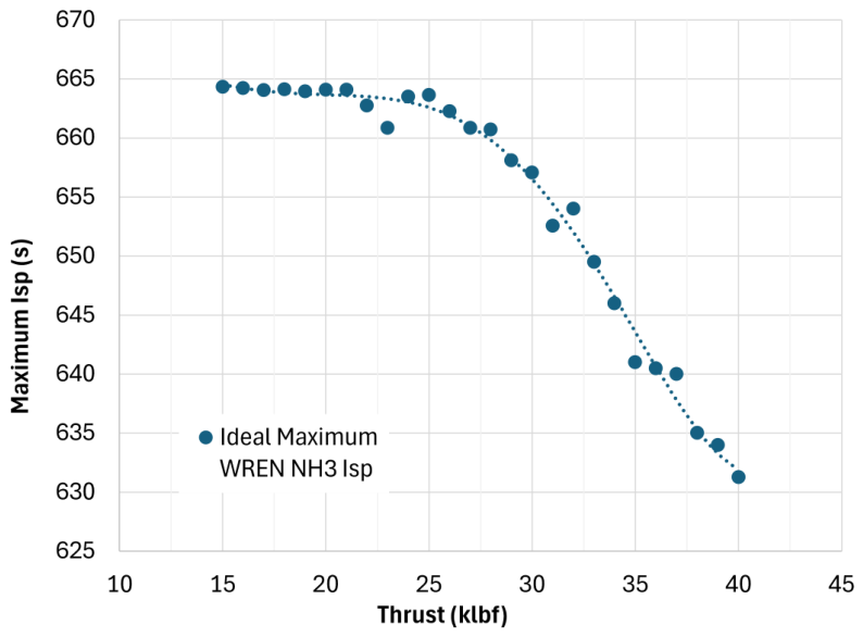
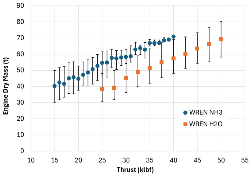
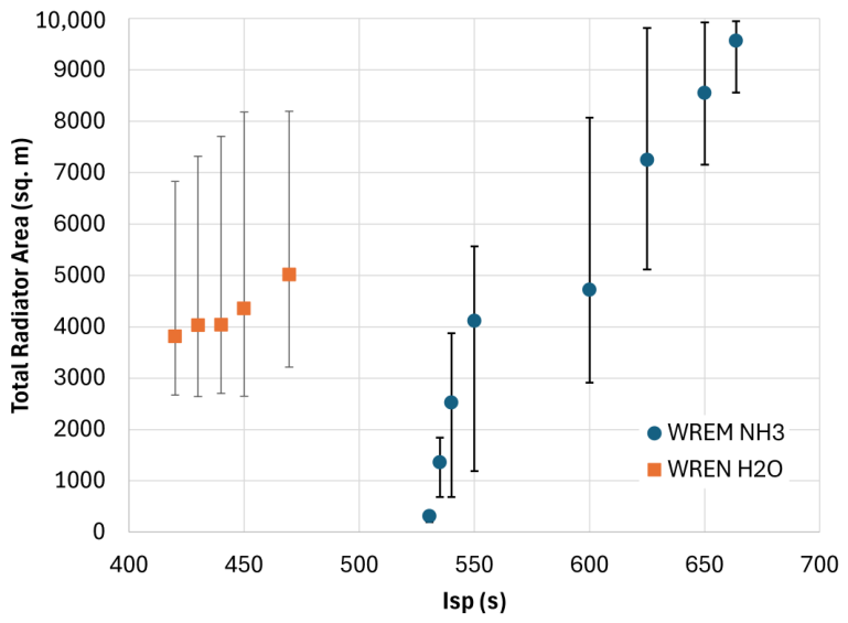
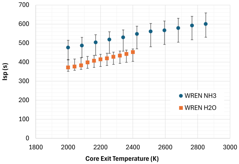
Figure 9, Figure 10, Figure 11 and Figure 12 show the results of the parametric analysis using the optimization program of the WREN cycle OOP model for NH3 and H2O. This includes changes to thrust in Figure 9 and Figure 10, I s p in Figure 11, and NTP core exit temperature in Figure 12. For the two latter analyses, the thrust remains fixed at the 25-klbf (111.21 kN) reference thrust. Figures which show the average optimized performance results also feature 5th to 95th percentile interval bars which show the distribution of converged results.
Figure 9 is the ideal equilibrium-theory based I s p found by the optimizer for the NH3 WREN at 2850 K NTP core exit temperature, thus it does not include the 5th to 95th percentile interval bars. Since an objective of the optimizer is to maximize I s p , this figure serves to demonstrate model behavior and the upper bounds of I s p without significant bias to other factors such as total mass.
A fifth-order polynomial trendline is overlaid with Figure 9 results. The I s p plateaus around a value of 663–665 s below ∼23 klbf (102.31 kN). Above this thrust and I s p diminishes continuously until the optimizer was unable to find a solution; stopping at a maximum of 40 klbf (177.93 kN). Hence, this range was limited to between 15 klbf (66.72 kN), to check if the values remain constant below 23 klbf at reasonable computational cost, and 40 klbf.
Figure 10 shows the dry mass of the WREN NH3 and H2O engines, in metric tons, as it relates to thrust. Please note to convert klbf of thrust to kN, the value is simply multiplied by ∼4.448 kN/klbf. The range of optimal solutions for NH3 decreases with increasing thrust, coinciding with the lack of convergent solutions at these higher regimes. While the H2O WREN design points could be further extended to higher levels of thrust, it is clear that the H2O WREN has a much larger potential thrust ceiling. In their dissertation, Nikitaeva [62] determined that a conventional H2O NTP-A expander cycle architecture operating at a core exit temperature of 2400 K limited thrust to ∼48 klbf (213.5 kN) due to a combination of factors including designed reactor power limit, core cladding erosion rates, fixed nozzle design, and turbopump complexity. For this reason, the H2O WREN model was modeled up to a thrust of 50 klbf (222.4 kN). Results of NH3 WREN thrust; however, fall below the maximum potential thrust of NTP-A NH3 (∼42.5 klbf or 189.0 kN). Future work is required to understand the factors which will limit the H2O WREN, and whether it may be optimized for higher values.
Setting the optimizer to solve WREN with a fixed I s p and thrust, the radiator area, which is effectively the main driver of system mass, is calculated in Figure 11 as a function of I s p . Due to the thermodynamic qualities of H2O in CEA, the WR compression ratio was constrained to a high value (≳3). Numbers lower than 3 tended to fail, with cycle balance producing pressures and temperatures that would cause a gas to liquid phase change, thus the H2O nuclear core outlet temperature was allowed to float for this case, but was maximized up to 2400 K if possible. NH3 I s p tended to vary with WR compression ratio alone, where the lower I s p bound for WREN NH3 correlated with the minimum allowed 1.01 compression ratio. Note the limited design variation of radiator area at this compression and at the upper bound of radiator area.
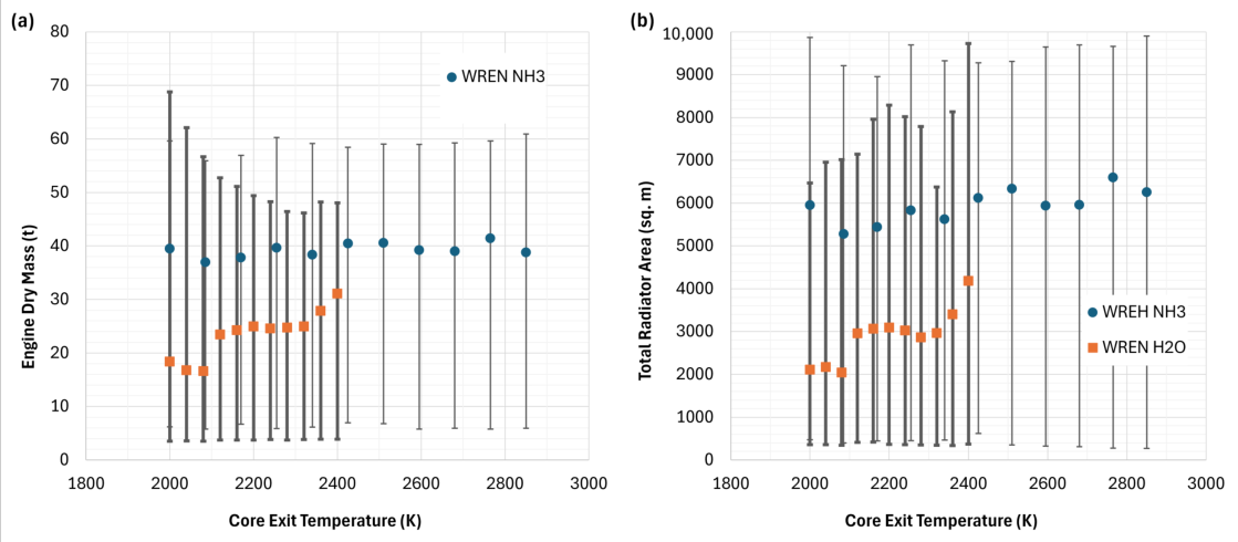
As mentioned previously, core life can be drastically extended by decreasing the core exit temperature. Figure 12 shows the resultant I s p of the H2O and NH3 WREN system as the nuclear core exit temperature is decreased from its maximum down to 2000 K. Thrust was constrained at 25 klbf. System mass and radiator size were found to not correlate strongly with reactor outlet temperature when maximizing I s p is sought, as is demonstrated by the extremely wide result intervals shown in Figure 13.
Even after decreasing the core to 2000 K, the I s p of either propellant is still 50–150 s higher than their respective NTP-A counterparts. This has considerable implications to the use of WREN as a high efficiency, long-term space tug system that may be supported by ISRU architecutre.

3.3. System Performance Comparison

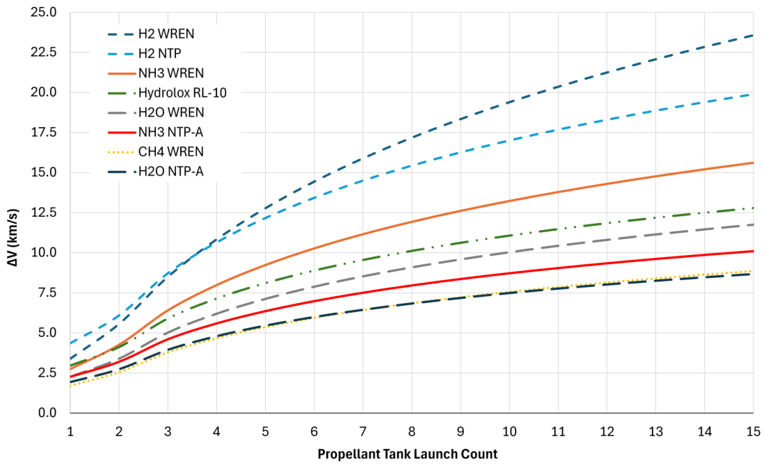
Figure 14 shows the resultant Equation (16) Δ V of each tank-engine system from Table 2, Table 3 and Table 5 as a function of tank launches up to 15. Please note the first two propellant launches are of inline tanks and the rest are drop tanks.
Among these systems, the H2 WREN, H2 NTP, and NH3 WREN vehicles were the only three to exceed a Δ V of 15 km/s within 15 launches. These are also the only systems which surpass hydrolox across Δ V performance. After about 5 tank launches, WREN LNH3 maintains a gap of ∼3.75 km/s below LH2 NTP for every tank to orbit.
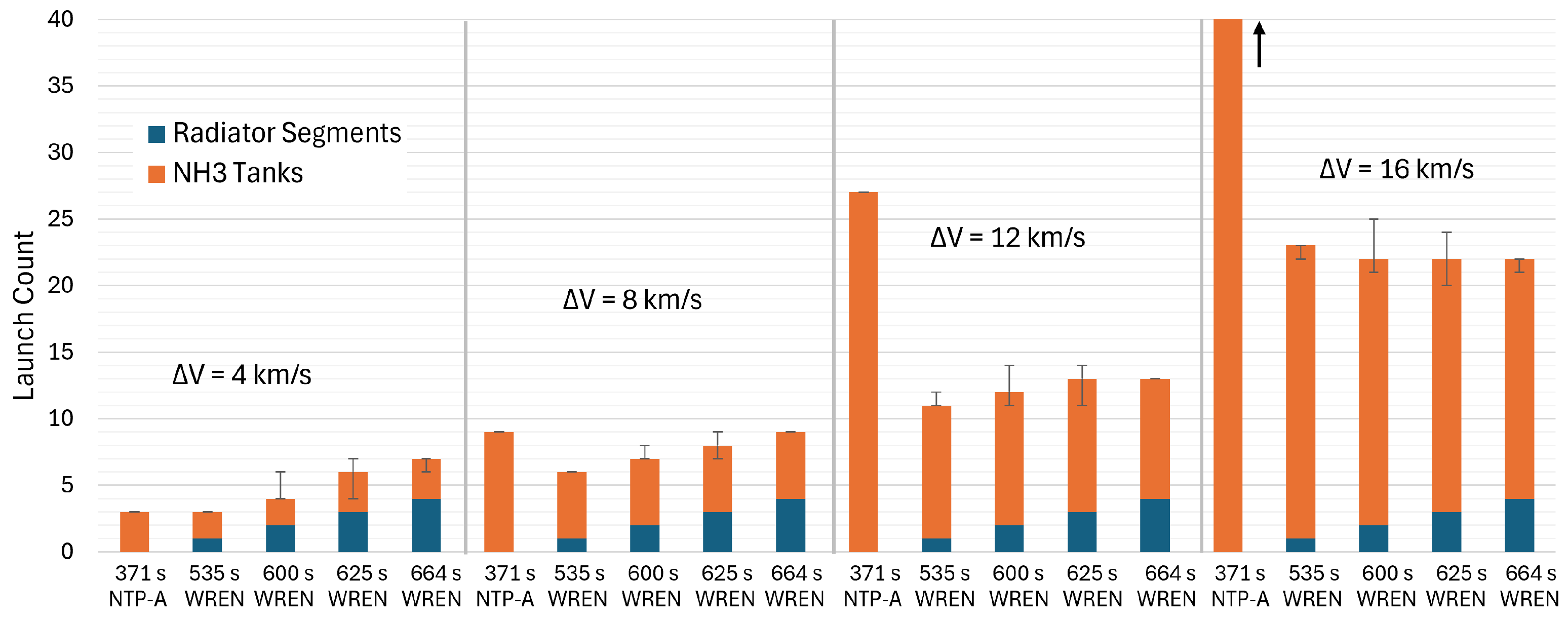
An important question regarding the use of WREN is whether the savings in propellant is worth the number of launches required to construct the radiators, assuming the 2500 m2 radiator limitation and combined inline and drop tank strategy. To demonstrate this, the NH3 WREN I s p variation analysis is revisited. Using resultant I s p of 535, 600, 625, and 664 s, of which the minimum and maximum of the set represent the approximate smallest and largest convergent models, the WREN NH3 vehicle is compared with the conventional NH3 NTP-A of Table 3. This comparison is made in terms of required tank and radiator launch count to orbit to achieve a specified Δ V.
Figure 15 shows the results of this analysis. Clearly, a large radiator acreage heavily constrains the tank launch count at high Δ V. Excluding the WREN engine and payload, the total number of launches to attain 12 km/s is reduced from 27 to only 13 total at the maximum WREN LNH3 I s p and 625 s system, of which only 9 launches are for propellant tanks; a third of the propellant required for NTP-A. This increases to an 80% reduction at 16 km/s, where NTP-A requires a total of 86 tanks not shown in Figure 15.
Opportunities for use of alternative propellant systems can be generalized by the mass fractions in which the rocket equation begins to favor the respective propellant over traditional NTP. LNH3 can be stored at the same internal pressure as LH2, thus both tanks will be constructed of the same strength to weight material. Assuming the engine and payload mass are negligible, that is to say the Δ V becomes so large that the system mass fraction approaches the mass fraction of the storage tanks to the propellant, i.e.,
R = m v + m p , t m v + m p + m p , t m p , t m p + m p , t
and each tank is at the same internal pressure, then there will be a notional crossover point in the rocket equation in which each propellant-engine system will have a higher Δ V ceiling without consideration to a particular arrangement of inline tanks, drop tanks, or payload.
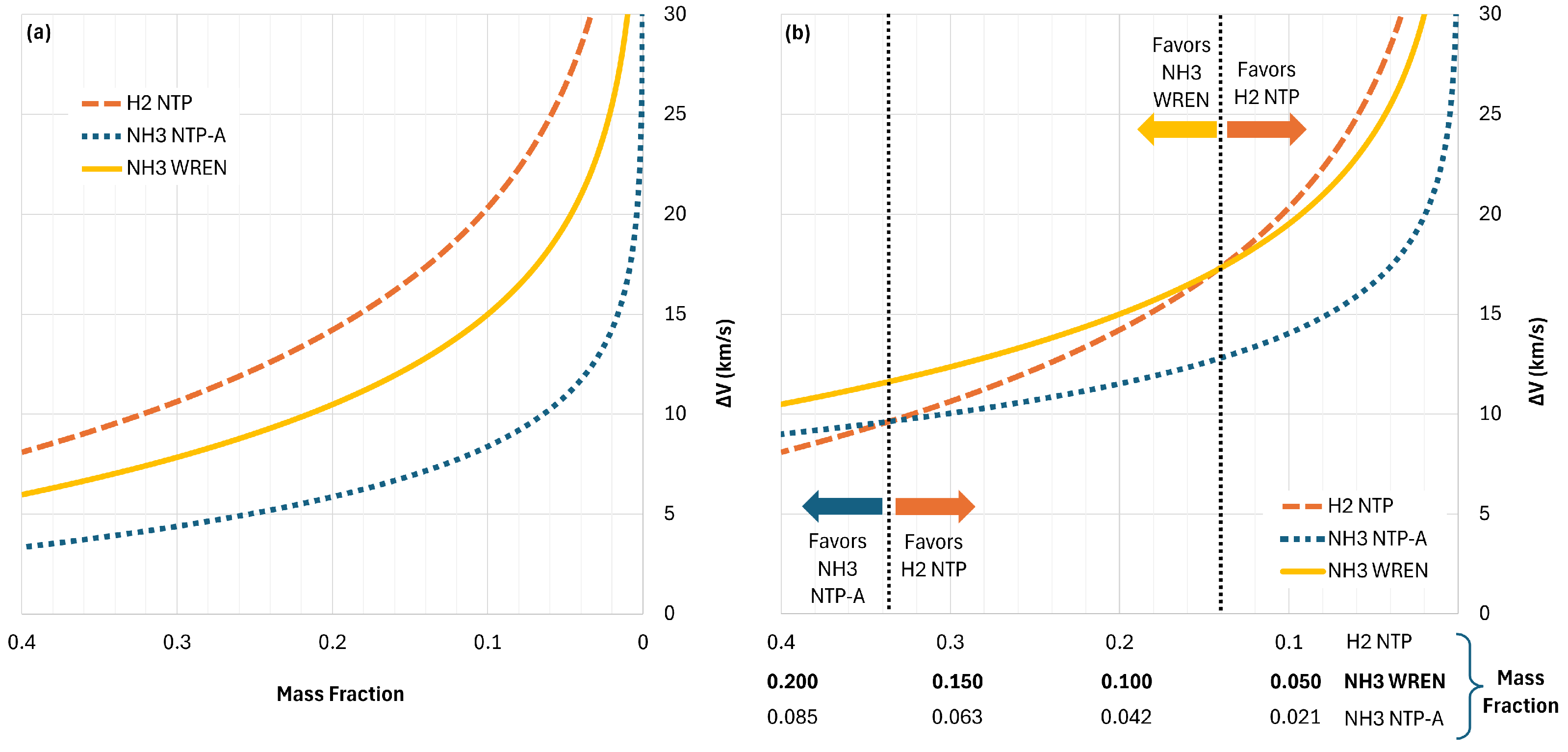
Extending results of Figure 14 to an arbitrarily large number of tanks satisfies Equation (17) approximation, where H2 NTP, NH3 NTP-A, and NH3 WREN approach an R of 0.177, 0.071, and 0.071, respectively; corresponding to their propellant types. The “cross-over” in terms of Δ V preference will then occur at the same R for both NH3 systems with reference to H2 NTP. However, due to the WREN NH3 systems larger I s p , it will have a separate H2 NTP R value for a greater Δ V ceiling.
Figure 16a provides the Δ V of the 25-klbf H2 NTP, NH3 NTP-A, and WREN NH3 systems simply as a function of R.
Traditional H2 NTP I s p is about 900 s, or 2.43 and 1.36 times the NH3 NTP-A and NH3 WREN, respectively. Therefore, the cross over for the respective systems occurs when the natural logarithm of their LNH3 tank mass fractions is less than 2.43 and 1.36 times that of the LH2 tank mass fraction, respectively [15]. Taking into account the solved mass fraction of each system, the two NH3 system lines in Figure 16a can be shifted to correlate with the new cross-over R values, as shown in Figure 16b.
Here, the rocket equation favors both NH3 vehicles at an H2 NTP R value ≳ 0.34, corresponding to a Δ V favorability of ≲9.6 km/s. The improved I s p of the WREN shifts this favorability to H2 NTP R ≳ 0.14. This implies that the WREN NH3 vehicle Δ V ceiling is favorable up to ∼17.2 km/s compared to traditional H2 NTP for design conditions where the tank wet mass is the dominant mass on the vehicle.

4. Discussion

4.1. Interpretation

Within the assumptions of the present model, NH3 and H2O emerge as the most promising alternative WREN propellants, although they favor different applications. At the 25-klbf (111.21 kN) reference thrust, NH3 WREN attains an I s p of approximately 664 s, compared with approximately 470 s for H2O WREN. The higher NH3 performance is obtained at a near-maximum NTP WR compression ratio and requires a comparatively large driver-gas flow rate and radiator area. The H2O system, in contrast, requires a similarly high WR compression ratio but operates with a lower driver-to-motive-gas flow-rate ratio and a smaller Brayton core thermal power. Consequently, its modeled engine mass is approximately 28.6 t, compared with 46.2 t for NH3, and its radiator area is approximately 2901 m2, compared with 8333 m2 for NH3. These results suggest that NH3 is more attractive for long-duration, high-energy transit missions, while H2O may be more appropriate for higher-thrust applications in which engine dry mass and radiator deployment are dominant constraints.
The thrust parametric results in Figure 9 and Figure 10 reinforce this distinction. The NH3 WREN I s p plateaus near 663–665 s below approximately 23 klbf (102.31 kN) and decreases steadily as thrust increases toward 40 klbf (177.93 kN), beyond which the present optimizer did not identify feasible solutions. H2O WREN exhibited a broader range of converged designs, enabling a higher thrust ceiling, which is consistent with current H2O NTP-A studies [22].
These model behaviors are a result of the energy exchange requirements within the NTP WR and the constraints of radiator area. As motive gas flow rate ( m ˙ 4 5 ) increases to match a higher NTP thrust, the CBC driver fluid mass flow rate ( m ˙ 5 c 6 c ) must also increase to ensure the work of compression and expansion are equal. This implies a larger required P W r e j e c t , which is directly correlated with radiator size. More importantly, the specific heat capacity of NH3 tends to be much higher than H2O at NTP-A conditions [62], thus the compression work produced from expansion of the drive gas is much higher for a given thrust. This indicates the radiator needs to operate at an impractically low temperature compared with its available area to maintain CBC powertrain balance at sufficiently high thrust. Hence, the larger thrust availability of H2O WREN in Figure 10 and the diminishing maximum I s p in Figure 9. At low thrust, by contrast, the NTP WR can use the full NTP compression ratio ( p 5 / p 4 ) since the radiators are below there area limit, resulting in the I s p plateau.
A principal advantage of the WREN architecture is that the maximum propellant temperature is produced downstream of the NTP core. Therefore, the reactor outlet temperature can be reduced without an equivalent reduction in nozzle-inlet temperature or I s p . The parametric results in Figure 12 show that, even when the NH3 and H2O core outlet temperatures are reduced to 2000 K, the predicted I s p remains approximately 50–150 s higher than that of the corresponding conventional NTP-A systems [12]. This decoupling of reactor temperature from final propellant temperature provides performance benefits in both propellant utilization and potential core endurance. If the endurance trend shown in Figure 3 is considered qualitatively, reducing the core outlet temperature could potentially increase cumulative burn duration into the tens-ofhours regime. This would be particularly important for reusable space-tugs, vehicles requiring multiple departure burns, and bimodal systems expected to remain operational over several mission legs.
The I ρ results provide a second important interpretation. Of the WREN alternative propellants, NH3 and H2O improve upon their respective conventional NTP-A counterparts sufficiently to become competitive with both methalox and hydrolox CCP on a volumetric basis. Optimization within the established cycle constraints and assumed WR limits produced I ρ values of approximately 451.2 × 10 3 and 469.6 × 10 3   kg · s m 3 for NH3 and H2O, respectively. These values are nearly identical to that of the RL-10 hydrolox reference system. At a first-order level, this indicates that NH3 and H2O WREN can provide a similar total impulse per unit stored-fluid volume to hydrolox. Accordingly, the WREN systems can mitigate the large launch-fairing volume required to deliver a given quantity of impulse to orbit for conventional LH2 NTP.
Equivalent I ρ does not; however, imply equivalent mission Δ V . The vehicle mass fraction must also account for tank structure, engine dry mass, and payload. Once the modeled tank mass fractions are included, H2 WREN, H2 NTP, and NH3 WREN are the only systems considered that surpass hydrolox. The other systems require considerably more drop-tank launches to achieve a Δ V of 15 km/s, making them comparatively poor candidates under the assumed launch architecture.
The launch-count comparison also shows that the large dry mass of the WREN engine does not necessarily eliminate its mission-level advantage. For an NH3 mission requiring 12 km/s, the modeled launch count decreases from 27 tank launches for conventional NH3 NTP-A to 9 launches for the highest-performing NH3 WREN cases. At 16 km/s, the calculated reduction in tank launches approaches 80%. Thus, although the WREN radiator and power-conversion system impose a major initial dry-mass and launch penalty (2–6 launches), that penalty is quickly amortized as mission Δ V and required propellant mass increase. At this fidelity of analysis; however, the maximum performing NH3 WREN requires a similar number of total launches of tanks and radiators to its lower I s p variations at a moderate Δ V . Thus, careful consideration must be given to the size of the NTP WR compression ratio in terms of mass fraction.
For lower- Δ V missions, the benefits are not nearly as clear. The present results do not establish that WREN is preferable to conventional NTP-A for routine cislunar transport, where the radiator and engine dry mass may dominate the relatively modest propellant requirement. This may apply best to H2O WREN, where an apparent high T/W ceiling with a CCP-comparable I s p on a semi-permanent cislunar transport architecture can rapidly out-compete H2O NTP-A. Addressing this gap in applications will require a higher-fidelity analysis within the lower- Δ V design space, including repeated use, specific orbital maneuvers, payload delivery cadence, and the potential value of the CBC in an NEP or power-generation mode. A reusable tug completing many missions could distribute its initial dry-mass penalty across a large cumulative delivered mass, even if WREN is not optimal for a single isolated maneuver.
Translunar and interplanetary targets such as Mars appear more favorable for NTP-A propellants used through WREN propulsion because the reduced tankage and initial packaged volume become increasingly important as Δ V rises. The NH3 WREN system is especially promising in this regime. Water WREN may also retain value for missions in which water is already carried for life support, radiation shielding, thermal control, or ISRU feedstock. Such multifunctional use could improve its effective system-level mass fraction beyond that represented by the propulsion-only comparison in this work.
The generalized mass-fraction analysis further clarifies when NH3 WREN becomes competitive with H2 NTP. It is estimated that a combined RBO and ZBO H2 tank vehicle will have an asymptotic mass fraction of approximately R 0.177 . Under this assumption, the LNH3 WREN vehicle has a comparatively higher Δ V ceiling because it combines improved I s p with a lower limiting tank mass fraction at equivalent internal pressure. It is therefore a credible alternative to H2 NTP for vehicles in which tank wet mass composes the majority of the initial vehicle mass. If only RBO storage is assumed; however, and the H2 tank is constructed from the same class of material and operated at the same internal pressure as the LNH3 tank, the H2 mass fraction may be as low as R 0.035 for a 7000-series aluminum design, according to Foulds et al. [15]. Under that optimistic short-duration storage assumption, a multi-launch, high- Δ V mission becomes preferential to LH2 NTP.
A realistic multi-launch, high- Δ V , long-duration mission would likely employ a combination of RBO and ZBO tanks. The effective LH2 mass fraction would therefore lie somewhere between 0.035 and 0.177, depending on mission CONOPS and payload. The 25-klbf NH3 WREN shifts the crossover with H2 NTP to an LH2-vehicle mass fraction of approximately R 0.14 , which lies within this realistic RBO–ZBO range. The corresponding idealized Δ V ceiling is approximately 17.2 km/s under tank-dominated conditions. It can therefore be inferred that NH3 WREN may provide a higher Δ V ceiling than H2 NTP for some long-duration missions whose H2 storage system approaches the heavier end of the RBO–ZBO mass-fraction range. This is not a universal advantage over LH2; rather, it identifies the storage system penalty at which the density and storability of LNH3 overcome the higher I s p of LH2 NTP.
Additionally, the LNH3 mass fraction at which the crossover occurs is equivalent for NH3 WREN and conventional NH3 NTP-A because both systems use the same propellant and nominal tank technology. The higher I s p of WREN instead changes the corresponding crossover mass fraction of the competing H2 NTP vehicle. This distinction indicates that there is a margin of permissible WREN dry mass within the region favored by the rocket equation. Therefore, the larger WREN engine dry mass is not necessarily detrimental when competing with H2. Nevertheless, this conclusion becomes weaker as payload and engine dry mass represent a larger fraction of the initial vehicle mass, as is the case for low- Δ V missions.

4.2. Limitations and Future Research

The optimization program considered in this work, while capable of converging to reasonably consistent solutions, requires a larger number of independently obtained solutions to establish statistical confidence in the reported optima and feasibility boundaries. The present framework samples 15,000 initial designs and locally refines the 50 highest-performing candidates. Although this approach identifies repeated clusters of feasible solutions, it does not guarantee discovery of the global optimum in a highly constrained and potentially discontinuous design space. The average parametric results are noticeably variant from a trendline, particularly for propellants whose results are near the radiator constraints of the CBC powertrain. Future analyses should repeat the stochastic search with a larger number of random seeds, increase the initial population and number of refined candidates, and quantify the probability that additional sampling produces a materially better solution. Alternative global methods should also be compared with the present Monte-Carlo/Nelder–Mead method. A formal multi-objective treatment would better expose the Pareto trade among I s p , thrust, radiator area, engine mass, core temperature, and WR compression ratio. Reporting a Pareto frontier would also avoid implying that one optimized design is universally preferred when different missions may assign substantially different value to different performance parameters.
The present study was conducted at a NASA Pre-Phase A, concept studies level [75]. A subsequent Phase A study should additionally propagate uncertainties in component performance, mass models, structural and thermal limits, and mission-level requirements through the OOP design space rather than treating these quantities solely as deterministic constraints. Sensitivity and uncertainty analyses will be used to identify which assumptions most strongly affect feasibility boundaries and whether the preferred design region remains robust as higher-fidelity WR, structural, radiator, and mission models are introduced.
The WREN model does not resolve the time-dependent shock and expansion-wave structure within the WR channels, finite channel width, leakage, boundary layers, EGR, or gas mixing. The assumed WR pressure ratios and efficiencies are informed by prior experiments, but their simultaneous realization at the temperatures, pressures, molecular weights, and mass-flow ratios required by WREN has not been demonstrated. The assumption of equivalent compression and expansion work within the WR control volume also requires validation for systems with unequal motive- and driver-gas mass-flow rates. Detailed one-dimensional wave-diagram calculations followed by multidimensional CFD are needed to determine WR dimensions, operation, thermal loading, and achievable compression efficiency for each propellant.
Thermochemical properties are presently calculated using CEA equilibrium states. This approach does not capture finite-rate shock chemistry, non-equilibrium cracking, species freezing during nozzle expansion, or recombination as the fluid exits the WR. The true performance could be higher than predicted if rapid shock heating increases the production of low-molecular-weight hydrogen species beyond equilibrium values. It could also be lower if dissociated species recombine before useful expansion or if chemical energy remains frozen in non-propulsive internal modes. Time-resolved chemical-kinetics calculations and shock-tube experiments are therefore required for NH3, H2O, and CH4 at representative WREN pressure, temperature, and residence-time conditions.
Dynamic loading within and around the WR represents an additional structural and life-limiting consideration. Repeated pressure waves generate cyclic loads, while WR rotation introduces additional inertial loading; at the elevated operating temperatures considered here, the resulting alternating stresses may interact with thermally activated creep and fatigue mechanisms. The magnitude and frequency content of these loads, and their relationship to the natural frequencies of the rotor and surrounding spacecraft architecture must therefore be established before structural feasibility can be assessed. Future work should use time-resolved CFD to determine pressure-wave timing and amplitudes followed by coupled thermal and structural FEA to evaluate alternating stresses, material constraints, and additional rotor cooling requirements. WR geometry and rotational speed may also provide design freedom to separate dominant excitation frequencies from structural resonances, but this must be demonstrated for the WREN operating regime rather than assumed from existing WR applications. At the vehicle level, biological shielding requirements and the associated separation between the reactor and crewed elements can produce long trusses with low-frequency bending modes. Consequently, as a generic call-to-action for most NTP and NEP architectures, future vehicle-level analyses should include the coupled effects of reactor shielding, truss and radiator flexibility, turbomachinery excitation, and spacecraft maneuvering when establishing structural mass and feasibility.
Radiator mass and area represent a major fraction of WREN dry mass, but the present radiator model is based on fitted specific-mass relationships and an assumed NaK heat-transport loop. The model retains the authors earlier H2–NaK heat-exchange treatment even though He is used as the CBC fluid for the alternative-propellant cases. Future work should compare He, H2, He–Xe, and other mixtures. It was found that radiators approximately 4 times larger than current NASA designs provide a significant advantage in total mission architecture mass savings and launch elements. The feasibility of mass, deployment, thermal control, and structural behavior of radiator areas approaching 10,000 m2 should be evaluated within the coupled vehicle-level structural and dynamic analyses described above.
Several engine component masses are estimated using historical specific-mass ( α ) relationships. Although conservative assumptions were intentionally selected, the resulting masses remain uncertain because the WREN architecture combines power levels and operating temperatures outside the range of many reference systems. The nozzle, skirt extension, some plumbing, and electrical hardware are excluded or simplified. Conversely, use of two separate reactor cores and historical turbomachinery scaling may overestimate mass relative to an integrated modern design. A component-by-component mass model with explicit geometry is therefore needed to establish credible uncertainty bounds.
The tank and launch-count analysis also contains simplifying assumptions. This model applies fixed launcher payload and fairing limits, fixed inline and drop-tank extraneous masses, idealized tank shapes, negligible propellant losses, and a constant 45 t payload. It also assumes that the engine and payload can be assembled independently of the tank launches and that all launch vehicles achieve their nominal payload capability. Because a campaign containing tens of launches would be strongly affected by launch and assembly operational considerations, the reported launch counts should be interpreted as comparative indicators rather than complete mission plans.
The ideal rocket equation neglects gravity losses, steering losses, residual propellant, and the timing of drop-tank disposal. These effects may be especially important for the relatively low T/W of the H2 and NH3 WREN configurations. Alternatively, the higher T/W of H2O WREN has the potential of circumventing non-impulsive maneuver losses. Future trajectory optimization should consider cislunar tugs, conjunction- and opposition-class Mars missions, abort requirements, drop-tank staging, and the possible combined use of NTP and NEP modes. This analysis is necessary to determine whether the higher ideal Δ V translates into shorter trip time, greater payload, or fewer launches.

5. Conclusions

This study has demonstrated that wave-rotor-enhanced nuclear (WREN) propulsion could provide a viable pathway for using higher-density alternative propellants in solid-core NTP systems while overcoming much of the I s p penalties associated with their greater molecular weights. Incorporating NASA CEA thermochemistry into the WREN object-oriented systems model enabled the chemical decomposition and thermodynamic behavior of H2, NH3, H2O, and CH4 to be evaluated throughout the coupled NTP and closed Brayton cycles. For the 25-klbf (111.21 kN) baseline systems, WREN produced vacuum I s p values of approximately 664 s for NH3, 470 s for H2O, 360 s for CH4, and 1424 s for H2. The corresponding density-impulse ( I ρ ) values for NH3 and H2O, respectively, were comparable to hydrolox chemical propulsion. Parametric analysis further showed that reducing the NH3 and H2O reactor-core outlet temperatures to 2000 K still produced an I s p approximately 50–150 s greater than their conventional NTP-A counterparts, indicating that WREN may simultaneously improve propellant efficiency and extend reactor-core life. When the engine results were incorporated into a simplified tank-launch and rocket-equation analysis, WREN NH3 was one of only three systems considered to exceed 15 km/s within 15 tank launches. For a representative 12 km/s requirement, the highest-performing NH3 WREN designs reduced the combined tank and radiator campaign from 27 launches for conventional NH3 NTP-A to 13 launches, demonstrating that the fixed mass and deployment penalty of the WREN power-conversion system can be offset by propellant savings at sufficiently high mission Δ V .
Within model limitations, the present work demonstrates that WR superheating can fundamentally alter the trade between propellant performance and storage density. The results do not establish that WREN is preferable for every mission, but they identify a physically meaningful design region in which the fixed mass of the power-conversion and radiator system can be offset by reduced propellant tankage, improved core endurance, and potentially reusable bimodal capability. This region is sufficiently promising to justify continued component-level development and mission-specific evaluation.
The systems analysis and parametric studies identified radiator performance, WR thermal-fluid behavior, and preferred Δ V regime as the principal areas requiring higher-fidelity investigation. Future research should include multidimensional CFD, finite-rate chemical-kinetics modeling, and conjugate heat-transfer analysis of the WR, nozzle, and radiators under representative NH3 and H2O operating conditions. Experimental studies are also required to assess fluid-surface interactions under repeated dynamic loading from shock-heated alternative propellants. At the system level, the optimization framework should be expanded through repeated global searches and multi-objective methods, while the comparative vehicle model should incorporate detailed tank geometry, boil-off and cryocooling requirements, finite-burn trajectories, radiator deployment, reusable operations, and mission-specific payload and CONOPS assumptions.
Overall, the present results identify NH3 WREN as the most balanced alternative-propellant architecture considered. H2O WREN provides a complementary design point with lower engine mass, smaller radiator area, and potentially greater thrust scalability, although its lower I s p limits its ultimate Δ V ceiling. H2 WREN retains the greatest specific impulse but incurs a substantial engine and radiator mass penalty, whereas CH4 WREN does not achieve competitive density impulse and introduces unresolved graphite-deposition concerns. These findings emphasize that the preferred WREN propellant must be selected at the mission-architecture level rather than through isolated engine performance. By connecting WR pressure exchange, CBC power conversion, equilibrium thermochemistry, alternative-propellant storage, and launch-campaign analysis within a common systems framework, this work establishes a foundation for evaluating WREN-enabled NTP-A vehicles for reusable space-tugs, long-duration transportation systems, and high- Δ V interplanetary missions.

Author Contributions

Conceptualization, R.G.; methodology, R.G. and G.O.; software, G.O.; validation, R.G.; formal analysis, G.O.; investigation, R.G. and G.O.; resources, R.G. and G.O.; data curation, G.O.; writing—original draft preparation, G.O.; writing—review and editing, R.G.; visualization, G.O.; supervision, R.G.; project administration, G.O.; funding acquisition, R.G. All authors have read and agreed to the published version of the manuscript.

Funding

This research was funded in part by the National Aeronautics and Space Administration (NASA) through the NASA Innovative Advanced Concepts (NIAC) program, grant number 80NSSC23K0589.

Data Availability Statement

The data presented in this study are available on request from the corresponding author. The system model and its raw data are not publicly available due to copyright.

Acknowledgments

The authors would like to gratefully acknowledge Mike Houts for his insightful discussions on the nuclear thermal rocket modeling, and to Tony Colozza for discussions regarding parameters used in previous NASA Compass studies.

Conflicts of Interest

The authors declare no conflicts of interest.

Nomenclature

The following abbreviations and symbols are used in this manuscript:
AbbreviationDescription
AIAAAmerican Institute of Aeronautics and Astronautics
BWRBrayton-topping wave rotor
CBCClosed Brayton cycle
CEAChemical Equilibrium with Applications
CCPChemical combustion propulsion
CONOPSConcept of operations
DRADesign Reference Architecture
EGRExhaust-gas recirculation
ESAEuropean Space Agency
HeHelium
He–XeHelium–xenon mixture
HLVHeavy-lift vehicle
HPCGHigh-pressure compressed gas
HPDGHigh-pressure driver gas
ISROIndian Space Research Organisation
ISRUIn situ resource utilization
KAISTKorea Advanced Institute of Science & Technology
KANUTERKorea Advanced Nuclear Thermal Engine Rocket
KBKhA(Russian) Chemical Automatics Design Bureau
LCH4Liquid methane
LEOLow Earth orbit
LH2Liquid hydrogen
LH2OLiquid water
LNH3Liquid ammonia
LO2Liquid oxygen
LPCGLow-pressure compressed gas
LPDGLow-pressure driver gas
MOTMaximum operating temperature
NaKSodium–potassium alloy
NEPNuclear electric propulsion
NERVANuclear Engine for Rocket Vehicle Application
NGNew Glenn
NISTNational Institute of Standards and Technology
NTPNuclear thermal propulsion
NTP-AAlternative-propellant nuclear thermal propulsion
OOPObject-oriented programming
RBOReduced boil-off
RCSReaction control system
RP-1Rocket Propellant-1
SiC/SiCSilicon-carbide-fiber-reinforced silicon-carbide composite
SLSSpace Launch System
SSStarship
TLITranslunar injection
TPRTotal pressure ratio
TRLTechnology readiness level
WRWave rotor
WRENWave Rotor Enhanced Nuclear propulsion
ZBOZero boil-off
Symbols
ASurface Area, m2
gGravitational acceleration at the Earth’s surface, m s−2
hSpecific enthalpy, J kg−1
I s p Specific impulse, s
I ρ Density-impulse, kg · s m 3
kNumber of drop-tank launches
M W Average molecular weight, kg kmol−1
mMass, kg
nNumber of inline-tank launches
pPressure, bar
P R Pressure ratio
P W Thermal power, W
RStage final-to-initial mass fraction or ratio
R u Universal gas constant, J mol−1 K−1
TTemperature, K
VPropellant or tank volume, m3
m ˙ Mass flow rate, kg s−1
W ˙ Work rate, W
α Component specific mass, kg kW−1 or kg MW−1
γ Ratio of specific heats
Δ V Change in velocity, m s−1
η Polytropic or isentropic efficiency
ρ Fluid storage density, kg m−3
Subscripts
1–8Thermodynamic station numbers
AAlternative-propellant
avg Effective average
cClosed-Brayton-cycle stations
c h Chamber
comp Compression
dFull drop tank
e x Nozzle exit
ext . Extraneous tank-systems
eNozzle exit
f u l l Full propellant tank
iFull inline tank
pPropellant
rad Radiator
reject Rejected
t Propellant storage tank
vVehicle, including engine and payload
WR Wave Rotor

References

  1. Emrich, W.J. Principles of Nuclear Rocket Propulsion; Elsevier: Amsterdam, The Netherlands, 2023. [Google Scholar]
  2. Oleson, S.R.; Burke, L.M.; Mason, L.S.; Turnbull, E.R.; McCarty, S.; Colozza, A.J.; Fittje, J.E.; Yim, J.T.; Smith, M.; Packard, T.W.; et al. Compass Final Report: Nuclear Electric Propulsion (NEP)-Chemical Vehicle 1.2; Technical Report; NASA: Washington, DC, USA, 2021. Available online: https://ntrs.nasa.gov/citations/20210017131 (accessed on 14 July 2026).
  3. Finseth, J.L. Rover Nuclear Rocket Engine Program: Overview of Rover Engine Tests; NASA Contractor Report NASA-CR-184270; NASA: Washington, DC, USA, 1991. Available online: https://ntrs.nasa.gov/citations/19920005899 (accessed on 14 July 2026).
  4. Demyanko, Y.G.; Konyukhov, G.V.; Koroteev, A.S.; Kuzmin, E.P.; Pavel’ev, A.A. Yadernye Raketnye Dvigateli (Nuclear Rocket Engines); Norma-Inform Ltd.: Moscow, Russia, 2001. [Google Scholar]
  5. Seedhouse, E. The Engines. In SpaceX: Starship to Mars–The First 20 Years; Springer: Cham, Switzerland, 2022; pp. 40–57. [Google Scholar]
  6. Sutton, G.P.; Biblarz, O.; Morehart, J.H. Rocket Propulsion Elements; John Wiley & Sons: Hoboken, NJ, USA, 2026. [Google Scholar]
  7. ALUMNI Team; ArianeGroup; CEA; Framatome Space. ALUMNI Project: Executive Summary; ESA RFP/3-17832/22/FR/KR; European Space Agency: Paris, France, 2024. [Google Scholar]
  8. Chandra, A.; Varrier, M.; Bijukumar, K.S.; Jayan, N.; Narayanan, V. Engine Cycle Analysis and Configuration Studies for a Nuclear Thermal Rocket (NTR) Engine. Int. J. Energ. Mater. Chem. Propuls. 2025, 24, 79–95. [Google Scholar] [CrossRef] [Scilit]
  9. Nam, S.H.; Venneri, P.; Kim, Y.; Lee, J.I.; Chang, S.H.; Jeong, Y.H. Innovative Concept for an Ultra-Small Nuclear Thermal Rocket Utilizing a New Moderated Reactor. Nucl. Eng. Technol. 2015, 47, 678–699. [Google Scholar] [CrossRef] [Scilit]
  10. Dowdy, W. Application of High Density-Impulse Nuclear-Rocket Propellants in Aerobraking Spacecraft Assemblies. In Proceedings of the 4th Propulsion Joint Specialist Conference; Paper 574; AIAA: Reston, VA, USA, 1968. [Google Scholar] [CrossRef] [Scilit]
  11. Selcow, E.C.; Davis, R.E.; Perkins, K.R.; Ludewig, H.; Cerbone, R.J. Assessment of the Use of H2, CH4, NH3, and CO2 as NTR Propellants. AIP Conf. Proc. 1992, 246, 721–727. [Google Scholar] [CrossRef] [Scilit]
  12. Nikitaeva, D.; Thomas, L. Propulsion Alternatives for Mars Transportation Architectures. J. Spacecr. Rocket. 2023, 60, 520–532. [Google Scholar] [CrossRef] [Scilit]
  13. Yang, N.; Deng, J.; Wang, C.; Bai, Z.; Qu, J. High Pressure Hydrogen Leakage Diffusion: Research Progress. Int. J. Hydrogen Energy 2024, 50, 1029–1046. [Google Scholar] [CrossRef] [Scilit]
  14. Lemmon, E.W.; McLinden, M.O.; Friend, D.G. Thermophysical Properties of Fluid Systems. In NIST Chemistry WebBook, NIST Standard Reference Database Number 69; Linstrom, P.J., Mallard, W.G., Eds.; National Institute of Standards and Technology: Gaithersburg, MD, USA, 2005. [Google Scholar] [CrossRef] [Scilit]
  15. Foulds, C.; Greisen, D.; Nagarajan, H.; Eades, M. Vehicle-Level Performance Benefits of Ammonia Nuclear Thermal Propulsion. In Proceedings of NETS 2023 Propulsion: Materials and Testing; American Nuclear Society: Westmont, IL, USA, 2023. [Google Scholar]
  16. Al Ghafri, S.Z.S.; Swanger, A.; Jusko, V.; Siahvashi, A.; Perez, F.; Johns, M.L.; May, E.F. Modelling of Liquid Hydrogen Boil-Off. Energies 2022, 15, 1149. [Google Scholar] [CrossRef] [Scilit]
  17. Borowsky, J.; Charbonneau, J.; Dougherty, J.; Lagle, A.; Masse, N.; Mitchell, J.; Patel, D.; Veguilla, R.; Jayachandran, J. Mitigating Boil-Off in Cryogenic Spacecraft Propellant Tanks. 2023. Available online: https://digital.wpi.edu/downloads/9880vv41d (accessed on 14 July 2026).
  18. Notardonato, W.U.; Swanger, A.M.; Fesmire, J.E.; Jumper, K.M.; Johnson, W.L.; Tomsik, T.M. Zero Boil-Off Methods for Large Scale Liquid Hydrogen Tanks Using Integrated Refrigeration and Storage; NASA Kennedy Space Center: Merritt Island, FL, USA; NASA Glenn Research Center: Cleveland, OH, USA, 2017. [CrossRef] [Scilit]
  19. Borowski, S.K.; McCurdy, D.; Packard, T. Nuclear Thermal Propulsion (NTP): A Proven, Growth Technology for Fast Transit Human Missions to Mars. In Proceedings of the AIAA SPACE 2013 Conference and Exposition; AIAA: Reston, VA, USA, 2013; Paper 5354. [Google Scholar]
  20. Joyner, C.R.; Eades, M.; Hanks, D.; Jennings, T.; Kokan, T.S.; Levack, D.J.; Reynolds, C. NTP Design Derivatives and Enhancements for Lunar and Mars Missions. In Proceedings of the AIAA Propulsion and Energy 2019 Forum; Paper 4453; AIAA: Reston, VA, USA, 2019. [Google Scholar] [CrossRef] [Scilit]
  21. Wall, M. SpaceX Tests Huge Fuel Tank for Mars Colony Spaceship. Available online: https://www.space.com/34759-spacex-mars-spaceship-fuel-tank-test.html (accessed on 14 July 2026).
  22. Nikitaeva, D.; Thomas, D.L. Alternative Propellant Nuclear Thermal Propulsion Engine Architectures. J. Spacecr. Rocket. 2022, 59, 1149–1160. [Google Scholar] [CrossRef] [Scilit]
  23. Hintze, P.E.; Meier, A.J.; Shah, M.G.; DeVor, R. Sabatier System Design Study for a Mars ISRU Propellant Production Plant. In Proceedings of the International Conference on Environmental Systems; Report No. KSC-E-DAA-TN57348; NASA: Washington, DC, USA, 2018. Available online: https://api.semanticscholar.org/CorpusID:134245477 (accessed on 14 July 2026).
  24. Smith, M.; Craig, D.; Herrmann, N.; Mahoney, E.; Krezel, J.; McIntyre, N.; Goodliff, K. The Artemis Program: An Overview of NASA’s Activities to Return Humans to the Moon. In Proceedings of the 2020 IEEE Aerospace Conference; IEEE: Piscataway, NJ, USA, 2020; pp. 1–10. [Google Scholar] [CrossRef] [Scilit]
  25. Gosse, R.; Roy, S.; Tonks, M.; Watson, J.; Osborne, G.; Mahmood, H.; Burrows, S.K.; Yadav, V.; Smith, J.; Mark, T.; et al. New Class of Bimodal NTP/NEP with a Wave Rotor Topping Cycle Enabling Fast Transit to Mars. NASA Innovative Advanced Concepts Phase I Final Report. 2024. Available online: https://ntrs.nasa.gov/citations/20260003811 (accessed on 14 July 2026).
  26. Gordon, S.; McBride, B.J. Thermodynamic Data to 20,000 K for Monatomic Gases; Technical Report; NASA: Washington, DC, USA, 1999. Available online: https://ntrs.nasa.gov/api/citations/19990063361 (accessed on 14 July 2026).
  27. McBride, B.J. Thermodynamic Data for Fifty Reference Elements; National Aeronautics and Space Administration, Glenn Research Center: Cleveland, OH, USA, 2001. Available online: https://ntrs.nasa.gov/citations/20010021116 (accessed on 14 July 2026).
  28. Nelson, S.T.; Grey, J.; Williams, P.M. Conceptual Study of a Liquid-Core Nuclear Rocket. J. Spacecr. Rocket. 1965, 2, 384–391. [Google Scholar] [CrossRef] [Scilit] [PubMed]
  29. Houts, M.G.; Thomas, L.D.; Nassersharif, B. Centrifugal Nuclear Thermal Rocket Challenges and Potential. In Proceedings of the 45th Annual AAS Guidance, Navigation and Control Conference; Paper AAS 23-175; NASA: Washington, DC, USA, 2023. Available online: https://ntrs.nasa.gov/api/citations/20230000621 (accessed on 14 July 2026).
  30. Schroll, M.; Ziehm, W.; Frederick, R.; Thomas, L.D. Preliminary Study of Alternative Propellant Performance for a CNTR. In Proceedings of the Marshall Jamboree & Poster Expo, Huntsville, AL, USA, 15 May 2024; NASA: Washington, DC, USA, 2024. Available online: https://ntrs.nasa.gov/citations/20240004703 (accessed on 14 July 2026).
  31. Allen, J.; Johns, M.; Patterson, M.; Houts, M.; Heidet, F.; Smith, N.V.; Foster, J.E. Overview of High-Performance Centrifugal Nuclear Thermal Rocket Propulsion System. In Proceedings of the ANS Virtual Winter Meeting; American Nuclear Society: Westmont, IL, USA, 2020; Available online: http://local.ans.org/ne/wp-content/uploads/2021/02/OverviewCNTR-ANS-Winter-2020-summary-paper.pdf (accessed on 14 July 2026).
  32. Zhang, Y. Advanced Nuclear Power Engine: A Brief Overview of Gas Core Reactor for Space Exploration. Int. J. Adv. Nucl. React. Des. Technol. 2023, 5, 53–71. [Google Scholar] [CrossRef] [Scilit]
  33. Santana, D.; Hollingsworth, D.K. Vaporization in Liquid-Core Nuclear Thermal Rockets. Nucl. Sci. Eng. 2025, 199, 653–678. [Google Scholar] [CrossRef] [Scilit]
  34. Gosse, R.C.; Osborne, G.; Mahmood, H.; Burrows, S.K.; Roy, S.; Watson, J.; Tonks, M.; Colozza, A.J. Nuclear Wave Rotor Bi-Modal Cycle for In-Space Propulsion. In Proceedings of the AIAA SCITECH 2024 Forum; Paper 1238; AIAA: Reston, VA, USA, 2024. [Google Scholar] [CrossRef] [Scilit]
  35. Osborne, G. Systems Level Design of Novel Bimodal Nuclear Space Propulsion Subsystems Using Object Oriented Programming. Master’s Thesis, University of Florida, Gainesville, FL, USA, 2024. Available online: https://ufdc.ufl.edu/en/UFE0061128/00001/pdf (accessed on 14 July 2026).
  36. Osborne, G.S.; Gosse, R.C. Propellant Alternatives of Nuclear Thermal Propulsion Using Wave Rotor Pressure Exchanges. In AIAA SCITECH 2025 Forum; AIAA: Reston, VA, USA, 2025; p. 0150. [Google Scholar] [CrossRef] [Scilit]
  37. Akbari, P.; Nalim, R.; Mueller, N. A Review of Wave Rotor Technology and Its Applications. J. Eng. Gas Turbines Power 2006, 128, 717–735. [Google Scholar] [CrossRef] [Scilit]
  38. Weatherston, R.C.; Russo, A.L.; Smith, W.E.; Marrone, P.V. Gasdynamics of a Wave Superheater Facility for Hypersonic Research and Development; Technical Report; Cornell Aeronautical Lab., Inc.: Buffalo, NY, USA, 1959. Available online: https://www.osti.gov/biblio/4244493 (accessed on 14 July 2026).
  39. Saad, G.M.; Squire, W. Application of the Wave Superheater to Nuclear Rockets. ARS (Am. Rocket Soc.) J. 1962, 32. Available online: https://www.osti.gov/biblio/4759108 (accessed on 14 July 2026).
  40. Squire, W. The Application of the Wave Superheater in Nuclear Rocket Systems. In Proceedings of the XIIIth International Astronautical Congress (Varna 1962); Springer: Vienna, Austria, 1964; pp. 818–829. [Google Scholar] [CrossRef] [Scilit]
  41. Mason, L.S.; Schreiber, J.G. A Historical Review of Brayton and Stirling Power Conversion Technologies for Space Applications. In Proceedings of the Space Nuclear Conference 2007; Paper E-16140; NASA: Washington, DC, USA, 2007. [Google Scholar]
  42. Satter, C.M. JIMO Follow-On Mission Studies. AIP Conf. Proc. 2005, 746, 249–257. [Google Scholar] [CrossRef] [Scilit]
  43. Dyson, R.; Rao, D.V.; Duchek, M.; Harnack, C.; Scheidegger, R.; Mason, L.; Juhasz, A.; Rodriguez, L.; Leibach, R.; Geng, S.; et al. Nuclear Electric Propulsion Brayton Power Conversion Working Fluid Considerations; Technical Report; NASA: Washington, DC, USA, 2022. Available online: https://ntrs.nasa.gov/citations/20220002293 (accessed on 14 July 2026).
  44. Akbari, P.; Copeland, C.D.; Tüchler, S.; Ferris, A.M.; Davidson, D.F.; Hanson, R.K. Investigation of Ammonia-Hydrogen Mixture as a Green Fuel for Jet Engines Using a Wave Reformer. In Proceedings of the AIAA SCITECH 2022 Forum, San Diego, CA, 3–7 January 2022; Paper AIAA 2022-2048; AIAA: Reston, VA, USA, 2022. [Google Scholar] [CrossRef] [Scilit]
  45. Juhasz, A. A Mass Computation Model for Light Weight Brayton Cycle Regenerator Heat Exchangers. In Proceedings of the 8th Annual International Energy Conversion Engineering Conference; Paper AIAA 2010-7087; AIAA: Reston, VA, USA, 2010. Available online: https://ntrs.nasa.gov/citations/20100026667 (accessed on 14 July 2026).[Green Version]
  46. Paxson, D.E. A General Numerical Model for Wave Rotor Analysis; NASA TM 105740; NASA: Washington, DC, USA, 1992; Volume 1. Available online: https://ntrs.nasa.gov/citations/19920022240 (accessed on 14 July 2026).
  47. Wilson, J.; Paxson, D.E. Jet Engine Performance Enhancement Through Use of a Wave-Rotor Topping Cycle; NASA TM 4486; NASA: Washington, DC, USA, 1993. Available online: https://ntrs.nasa.gov/citations/19940012997 (accessed on 14 July 2026).
  48. Welch, G.E. Wave Engine Topping Cycle Assessment. In Proceedings of the 35th Aerospace Sciences Meeting and Exhibit; Paper 707; NASA: Washington, DC, USA, 1997. Available online: https://ntrs.nasa.gov/citations/19970010414 (accessed on 14 July 2026).[Green Version]
  49. Tüchler, S.; Copeland, C.D. Experimental Results from the Bath μ-Wave Rotor Turbine Performance Tests. Energy Convers. Manag. 2019, 189, 33–48. [Google Scholar] [CrossRef] [Scilit]
  50. Paxson, D.E.; Nalim, M.R. Modified Through-Flow Wave-Rotor Cycle with Combustor-Bypass Ducts. J. Propuls. Power 1999, 15, 462–467. [Google Scholar] [CrossRef] [Scilit] [PubMed][Green Version]
  51. NASA. Chemical Equilibrium with Applications in MATLAB (CEAM) (MFS-33320-1); NASA: Washington, DC, USA, 2017. Available online: https://software.nasa.gov/software/MFS-33320-1 (accessed on 14 July 2026).
  52. Nelder, J.A.; Mead, R. A Simplex Method for Function Minimization. Comput. J. 1965, 7, 308–313. [Google Scholar] [CrossRef] [Scilit]
  53. Walter, C.E. Gas-Cooled Reactor Power Systems for Space; Technical Report; Lawrence Livermore National Lab.: Livermore, CA, USA, 1987. Available online: https://inis.iaea.org/records/ec04x-hr561 (accessed on 14 July 2026).
  54. Sager, P.H. Radiation Shield Requirements for Manned Nuclear Propulsion Space Vehicles. AIP Conf. Proc. 1992, 246, 1251–1258. [Google Scholar] [CrossRef] [Scilit]
  55. Rawlins, S.B.; Thomas, L.D. Feasibility of Low-Enriched Uranium Fueled Nuclear Thermal Propulsion in the Low-Thrust Region Below 16 klbf. Ann. Nucl. Energy 2022, 179, 109368. [Google Scholar] [CrossRef] [Scilit]
  56. Schnitzler, B.G. Small Reactor Designs Suitable for Direct Nuclear Thermal Propulsion: Interim Report; Technical Report; Idaho National Lab. (INL): Idaho Falls, ID, USA, 2012. [CrossRef] [Scilit]
  57. Morrison, C.G. Temperature and Power Specific Mass Scaling for Commercial Closed-Cycle Brayton Systems in Space Surface Power and Nuclear Electric Propulsion Applications. Nucl. Technol. 2020, 206, 1224–1239. [Google Scholar] [CrossRef] [Scilit]
  58. Tomboulian, B.N. Lightweight, High-Temperature Radiator for In-Space Nuclear-Electric Power and Propulsion. Ph.D. Thesis, University of Massachusetts Amherst, Amherst, MA, USA, 2014. Available online: https://scholarworks.umass.edu/server/api/core/bitstreams/ffbef0b8-00c9-4db8-b8b8-2227c9428b50/content (accessed on 14 July 2026).
  59. Ashcroft, J.; Belanger, S.; Burdge, W.; Clementoni, E.; Jensen, K.; Proctor, N.B.; Zemo-Fulkerson, A. Key Factors Influencing the Decision on the Number of Brayton Units for the Prometheus Space Reactor. AIP Conf. Proc. 2007, 880, 522–540. [Google Scholar] [CrossRef] [Scilit]
  60. Zhou, B.; Zhang, H.; Ji, Y.; Sun, J.; Sun, Y. Numerical Investigation on Turbulent Flow and Heat Transfer of Helium-Xenon Gas Mixture in a Circular Tube. Sci. Technol. Nucl. Install. 2021, 2021, 8356893. [Google Scholar] [CrossRef] [Scilit]
  61. Dankanich, J.W.; Litchford, R.J. NASA Envisioned Future Priorities for In-Space Transportation. In Proceedings of the International Astronautical Congress (IAC 2022); NASA: Washington, DC, USA, 2022. Available online: https://ntrs.nasa.gov/citations/20220013522 (accessed on 14 July 2026).
  62. Nikitaev, D. Implications of Alternative In-Situ Propellants Used in Nuclear Thermal Propulsion Engines. Ph.D. Thesis, The University of Alabama in Huntsville, Huntsville, AL, USA, 2021. Available online: https://louis.uah.edu/uah-dissertations/231/ (accessed on 14 July 2026).
  63. Dale, D.; Ruschau, A. NASA Hytec CMC Turbine Blade Durability. 2023. Available online: https://ntrs.nasa.gov/citations/20230008139 (accessed on 14 July 2026).
  64. Yousefi, M.; Donne, S.; Bahremand Abrasi, S.; Yousefi, M. Overall Reaction Rate Study of Thermal Methane Cracking in Non-Isothermal Conditions. J. Energy Power Technol. 2023, 5, 028. [Google Scholar] [CrossRef] [Scilit]
  65. Johnson, D.L. Kinetics of the Homogeneous Thermal Decomposition of Ammonia in the Shocktube. Ph.D. Thesis, Washington University in St. Louis, St. Louis, MO, USA, 1966. Available online: https://www.proquest.com/openview/ef269bba6a20ef616b836b9b19b68055/1?pq-origsite=gscholar&cbl=18750&diss=y (accessed on 14 July 2026).
  66. Davidson, D.F.; Kohse-Höinghaus, K.; Chang, A.Y.; Hanson, R.K. A Pyrolysis Mechanism for Ammonia. Int. J. Chem. Kinet. 1990, 22, 513–535. [Google Scholar] [CrossRef] [Scilit]
  67. Akin, D.L. Mass Estimating Relations. Ph.D. Thesis, University of Maryland, College Park, MD, USA, 2016. [Google Scholar]
  68. Lockheed Martin Space Systems Company. Fact Sheet: Space Shuttle External Tank; Lockheed Martin Space Systems Company: Littleton, CO, USA, 2008. [Google Scholar]
  69. Reynolds, C.B.; Joyner, C.R.; Kokan, T.S.; Levack, D.J.; Muzek, B.J. Mars Opposition Missions Using Nuclear Thermal Propulsion. In Proceedings of the AIAA Propulsion and Energy 2020 Forum; AIAA: Reston, VA, USA, 2020; Paper 3850. [Google Scholar] [CrossRef] [Scilit]
  70. Kumar, A. Advancements in On-Orbit Satellite Servicing. In Proceedings of the AIAA Aviation Forum and Ascend 2025, Las Vegas, NV, USA, 21–25 July 2025; AIAA 2025-4107; AIAA: Reston, VA, USA, 2025. [Google Scholar] [CrossRef] [Scilit]
  71. Xiao, Y.; Jin, Y.; Yan, H.; Dou, Y.; Cui, G.; Li, F.; Meng, T. Review and Prospect of On-Orbit Servicing Technologies. Adv. Astronaut. 2025, 8, 107–127. [Google Scholar] [CrossRef] [Scilit]
  72. SpaceX. Starship. Available online: https://www.spacex.com/vehicles/starship/ (accessed on 14 July 2026).
  73. Berger, E. Blue Origin Revealed Some Massively Cool Plans for Its New Glenn Rocket. Available online: https://arstechnica.com/space/2025/11/blue-origin-says-its-just-getting-started-with-the-new-glenn-rocket/ (accessed on 14 July 2026).
  74. Harnack, C.; Grella, E.; Greenhalge, S.; Duchek, M. Capabilities of Single Launch NTP and Chemical Spacecrafts for Cis-Lunar Tug Missions. In Proceedings of Nuclear and Emerging Technologies for Space (NETS 2023); NASA: Washington, DC, USA, 2023. Available online: https://ntrs.nasa.gov/citations/20230002758 (accessed on 14 July 2026).
  75. NASA. 3.0 NASA Program/Project Life Cycle. In NASA Systems Engineering Handbook; NASA: Washington, DC, USA, 2023. Available online: https://www.nasa.gov/reference/3-0-nasa-program-project-life-cycle/ (accessed on 14 July 2026).
Figure 1. NTP propellant options vapor pressure. Adapted from NIST [14].
Energies 19 04047 g001
Figure 2. Fast-conjunction-class Copernicus NTP concept vehicle. Adapted from NASA/TM—2014-218104, Borowski, McCurdy & Packard [19].
Energies 19 04047 g002
Figure 3. Projected Endurance of NTP nuclear cores with Hydrogen. Adapted from NASA report 20260003811, Gosse et al. [25].
Energies 19 04047 g003
Figure 4. Average chamber M W of propellants at their respective critical pressures using CEA. The corresponding pressures, in bar, are 220.6 for H2O, 113.6 for NH3, 46.0 for CH4, and 13.0 for H2.
Energies 19 04047 g004
Figure 5. Exploded view of a four port wave rotor. HPDG—High Pressure Driver Gas; LPDG—Low Pressure DG; LPCG—Low Pressure Compressed Gas; and HPCG—High Pressure CG. Adapted from NASA report 20260003811, Gosse et al. [25].
Energies 19 04047 g005
Figure 6. Four-port, through-flow wave rotor compression and expansion wave pattern. Adapted from NASA report 20260003811, Gosse et al. [25].
Energies 19 04047 g006
Figure 7. Wave rotor topped NTP rocket propellant line with numbered stations.
Energies 19 04047 g007
Figure 8. WREN system NTP cycle schematic.
Energies 19 04047 g008
Figure 9. Ideal I s p evaluation of the WREN optimizer model using NH3 propellant at a given thrust.
Energies 19 04047 g009
Figure 10. WREN engine dry mass results as a function of thrust class.
Energies 19 04047 g010
Figure 11. WREN radiator area required to produce fixed I s p .
Energies 19 04047 g011
Figure 12. WREN maximized I s p as a function of NTP core exit temperature.
Energies 19 04047 g012
Figure 13. Other parametric results as a function reactor core outlet temperature. (a) WREN total engine dry mass; and (b) WREN total radiator.
Energies 19 04047 g013
Figure 14. Δ V as a function of tank launch count for each system considered, assuming the propellant tank is launched separately to the rest of the vehicle dry mass.
Energies 19 04047 g014
Figure 15. Trade between radiator launch count and tank launch count for 25-klbf (111.21 kN) LNH3 class vehicles. The black arrow indicates the launch count is excessive and continues above the graph.
Energies 19 04047 g015
Figure 16. Comparison of Δ V ceiling of NTP, NTP-A NH3, and WREN NH3. (a) Δ V as a function of mass fraction, R; and (b) Δ V as a function of the respective mass ratios of each system shifted to highlight favored Δ V. The black dotted line indicates each Δ V cross-over point following this shift.
Energies 19 04047 g016
Table 1. Storage density of propellants and the required I s p to be comparable with the RL-10 and Raptor I ρ in a vacuum.
PropellantStorage DensityRequired I sp (RL-10)Required I sp (Raptor)
Hydrogen (LH2)70.8 kg/m36356 s5226 s
Methane (LCH4)423 kg/m31064 s875 s
Ammonia (LNH3)680 kg/m3661 s544 s
Water (LH2O)1000 kg/m3450 s370 s
Oxygen (LO2)1140 kg/m3--
Table 2. Approximate launcher vehicle mass and stage main propellant mass fraction.
PropellantTank-LauncherMass to LEO (t)Mass FractionTank Shape
LH2Inline-NG61.40.692Capsule
Drop-SS77.40.824Capsule
LNH3Inline-NG700.793Sphere
Drop-SS1000.929Sphere
LCH4Inline-NG700.785Sphere
Drop-SS1000.919Sphere
LH2OInline-NG700.794Sphere
Drop-SS1000.934Sphere
HydroloxInline-NG700.787Capsule
Drop-SS1000.921Capsule
Table 3. Specifications of engines being compared to WREN.
ClassNTP H2NTP-A NH3NTP-A H2OCP RL-10
Engine CycleExpanderExpanderExpanderClosed Expander
Core Exit Temp., K2850285024003350
I s p , s900371.0316.9465.5
I ρ × 10 3 kg · s m 3 63.7252317450
Engine mass (t)2.554.944.980.301
Source[3][22][22][74]
Table 4. Optimized design variable and objective results of 25-klbf (111.21 kN) class NH3 WREN model across five independent pseudo-random number seeds. Please refer to Figure 8 for station number variables.
Design Variable/ObjectiveSeed 1Seed 2Seed 3Seed 4Seed 5
NTP WR, p 5 / p 4 3.543.583.523.593.52
Brayton WR, p 2 c / p 1 c 3.551.733.403.503.56
Compressor 1, p 1 c / p 0 c 1.211.811.861.531.31
Radiator 2.1, T 10 c , K450.8541.1612.7514.2448.3
Radiator 2.2, T 3 c , K646.7373.0488.7579.5653.3
Vacuum I s p , s663.6664.7663.0665.0662.9
Engine Mass, t46.248.749.347.345.9
Table 5. Theoretical performance of 25-klbf (111.21 kN) class WREN NTP and NTP-A systems.
ParameterNH3H2OCH4H2
Exit Temperature, K3845297811923561
Vacuum I s p , s663.6469.6360.11424
I ρ × 10 3 kg · s m 3 451.2469.6152.3100.8
Engine Mass, t46.228.628.490.9
Engine T/W0.250.400.400.12
Radiator Area, m28333290172399989
Effective Equivalent Radiator Temp., K791.2844.0686.1737.4
Motive gas m ˙ , kg / s 17.124.131.57.96
Driver gas m ˙ , kg / s 26.413.812.013.3
Flow Rate Ratio1.550.570.381.67
NTP WR Compression Ratio3.543.593.042.93
NTP Core Power, MW t h 222.6135.672.5324.3
Brayton Core Power MW t h 368.9177.4203.6583.8
Thrust Power, MW361.9256.1196.3776.6
Disclaimer/Publisher’s Note: The statements, opinions and data contained in all publications are solely those of the individual author(s) and contributor(s) and not of MDPI and/or the editor(s). MDPI and/or the editor(s) disclaim responsibility for any injury to people or property resulting from any ideas, methods, instructions or products referred to in the content.