1. Introduction
The limited availability of conventional energy resources, particularly fossil fuels, is driving the development of renewable-energy technologies. In this context, hydrogen is regarded as one of the key components of the energy transition and is gaining importance as a secondary energy carrier with considerable potential, particularly in the transport sector. This perspective is supported by the fact that hydrogen can be efficiently produced through water electrolysis using electricity generated from renewable sources, such as photovoltaic systems and wind turbines. The implementation of hydrogen technologies is associated with several technical challenges, particularly those related to hydrogen production, distribution, and storage.
However, the increasing use of hydrogen in energy applications depends not only on the efficiency of its production, distribution, and storage, but also on achieving the required level of purity. Hydrogen quality is a critical parameter, especially in fuel-cell applications, where even trace concentrations of impurities can significantly affect system performance, service life, and operational safety. In proton-exchange membrane (PEM) fuel cells, contaminants such as CO, sulphur-containing compounds, NH
3, H
2O, and halogenated compounds are of particular concern, as they may cause catalyst deactivation and membrane degradation [
1,
2]. Therefore, the ISO 14687 standard specifies stringent limits for individual impurities and requires hydrogen intended for mobile applications to have a minimum purity of 99.97% [
3].
The required level of purity depends strongly on the hydrogen production method. Hydrogen produced by electrolysis is relatively pure, with hydrogen concentrations exceeding 99% when an alkaline electrolyser is used and reaching up to 99.5% in the case of a PEM electrolyser [
4,
5]. By contrast, technologies based on the gasification of coal or biomass, as well as natural gas reforming, generate gas mixtures containing significant amounts of CO, CO
2, CH
4, N
2, and other impurities [
6]. These components therefore necessitate additional separation and purification steps before the hydrogen can be used in its intended end-use application.
Several established technologies are currently available for hydrogen separation and purification. Among the most widely used is pressure swing adsorption (PSA), which is regarded as an industrial standard and can achieve hydrogen purities exceeding 99.99% [
7]. The PSA process is based on the selective adsorption of impurities at elevated pressure, followed by their desorption as the pressure is reduced [
8]. Membrane-based technologies represent another important group of separation methods, with palladium membranes exhibiting particularly high hydrogen selectivity. These membranes exploit the ability of palladium to dissociate molecular hydrogen into atomic hydrogen, which subsequently diffuses through the membrane, while the other gaseous components are retained [
9,
10,
11,
12]. However, their broader application is limited by the high cost of palladium and the susceptibility of the membrane surface to contamination [
13]. Cryogenic separation, which relies on differences in the condensation temperatures of the individual gas components, represents another viable alternative, although it is associated with high energy consumption [
14].
In recent years, MH-based hydrogen separation has emerged as a promising technological approach. Chen et al. describe the underlying principle as the selective absorption of hydrogen into a metallic or alloy matrix to form a hydride, while the remaining components of the gas mixture remain in the gaseous phase [
15]. Subsequent heating or pressure reduction induces the desorption of high-purity hydrogen [
16,
17]. In terms of achievable purity, advanced MH reactors have demonstrated the ability to produce hydrogen with purities exceeding 99.999% to 99.9999% (5N to 6N purity grade), even when low-grade feed gas mixtures are used. Moreover, the energy demand of this process is lower than that of PSA or cryogenic separation [
13].
The significance of MH lies not only in hydrogen separation itself, but also in their ability to store hydrogen directly within the same material structure. This dual functionality makes MH systems a unique solution that integrates hydrogen purification and storage into a single technological unit. Efficient hydrogen storage is another key prerequisite for the successful implementation of hydrogen technologies in the transport sector. However, this process is particularly challenging because of the very low volumetric energy density of hydrogen under standard conditions, necessitating advanced technologies based on compression, liquefaction, or chemical bonding to suitable carrier materials. In the transport sector, including passenger vehicles, buses, trains, marine vessels, and other means of transportation, hydrogen storage systems with high volumetric and gravimetric energy densities are essential. Only under these conditions can hydrogen technologies become competitive with conventional energy systems based on fossil fuels and batteries. Consequently, various hydrogen storage concepts and technologies have been intensively developed in recent years, with the aim of improving the energy density, safety, and overall efficiency of hydrogen storage systems.
Chemical hydrogen storage in the form of MH represents a promising alternative to conventional physical storage methods, such as high-pressure and cryogenic hydrogen storage, for both stationary and mobile applications. MH are formed through a reversible reaction between hydrogen and a metal, during which hydrogen atoms occupy interstitial sites within the metal crystal structure. This process enables hydrogen to be stored safely and compactly at relatively low pressures compared with conventional high-pressure storage systems [
18]. This storage method enables high volumetric hydrogen densities owing to the strong interaction between hydrogen atoms and the host metal lattice. A major advantage of MH is their ability to store hydrogen at temperatures close to ambient conditions, thereby offering enhanced safety compared with cryogenic storage systems. Despite these advantages, MH also exhibit several limitations that require further research and technological innovation. One of the main limitations is the low gravimetric energy density, which results in a high overall mass of MH-based storage systems. Another major challenge is the release of heat during hydrogen absorption into the interstitial sites of the metal lattice. This necessitates the implementation of efficient heat-exchange systems to remove the generated heat and maintain optimal reaction conditions. For example, when La–Ce–Ni-based alloys are used, approximately 1 MJ of heat is released per cubic metre of stored hydrogen during absorption, highlighting the need for effective thermal management in the practical application of these materials [
19]. However, when the thermal management system is optimally designed, the generated heat does not necessarily constitute a disadvantage, as it can be recovered and utilised in various auxiliary systems.
The removal of the generated heat must be ensured by cooling the MH alloy during hydrogen charging, which can be achieved using various approaches. To facilitate effective cooling, several types of MH storage vessels have been developed, with the principal geometric configurations classified as disc-shaped, chamber-type, and tubular vessels [
20,
21].
In chamber-type storage vessels, the MH alloy is contained within a relatively large cylindrical or cuboidal vessel. These configurations are typically used for high-pressure MH systems and stationary applications [
20]. In disc-shaped storage vessels, the reaction bed containing the MH alloy has a flat geometry. Hydrogen enters the vessel axially through a mesh covering the MH layer. The principal advantage of disc-shaped vessels is the rapid kinetics of hydrogen absorption into the metal alloy structure. However, each disc accommodates only a relatively small quantity of MH alloy and therefore stores a limited amount of hydrogen. Consequently, these vessels are not considered particularly suitable for transport applications [
22]. Tubular storage vessels are regarded as the most promising configuration for mobile applications. In this type of vessel, the MH alloy is packed into a steel tube. Yang et al. distinguish between two principal categories of tubular storage vessels. The first comprises vessels with diameters below 30 mm, which enable sufficient heat transfer in the radial direction [
21,
23]. The second category includes vessels with diameters exceeding 30 mm. In such configurations, the integration of a dedicated cooling system into the MH storage vessel is essential. The cooling system may employ passive or active cooling modules, or a combination of both [
24].
When active cooling modules are utilised, thermal management is based on forced convection. In MH storage vessels, active cooling systems may be implemented either internally or externally. These systems use a cooling medium, such as air or water, to remove the heat generated within the core of the MH storage vessel. Satya Sekhar et al. numerically compared four active-cooling configurations. External cooling was found to be more effective than a configuration employing a single internal cooling tube, primarily because of the larger available heat-transfer surface area. Further advantages of external cooling include a less pronounced reduction in hydrogen storage capacity for the same MH-bed dimensions and a simpler overall system design [
25].
Raju and Kumar optimised various heat-exchanger designs. In addition to a cylindrical shell containing several straight parallel tubes and a helical-coil heat exchanger, they analysed a configuration comprising 81 unfinned MH tubes arranged in a rectangular array, with three equally spaced baffles housed within a steel shell. During the study, selected geometric parameters, such as the tube diameter, were varied to evaluate their effects on the hydrogen charging time and the gravimetric capacity of the MH system. The results indicated that increasing the number of tubes filled with the MH alloy while reducing the spacing between them resulted in a lower pressure drop within the storage vessel [
26].
Another approach to efficiently removing heat from the core of a tubular MH storage vessel during hydrogen absorption involves the use of passive cooling modules in the form of heat exchangers. These modules constitute an integral part of the MH storage vessel and are manufactured from materials with high thermal conductivity, such as aluminium (237 W·m
−1·K
−1). In systems employing passive cooling modules, natural convection is considered the principal heat-transfer mechanism. Fins may be incorporated on either the internal or external surface of the storage vessel and can assume various geometries, including longitudinal fins [
27,
28], horizontal fins [
29], tree-shaped fins [
30,
31], honeycomb structures [
32], and other configurations.
Lottotsky et al. integrated a tubular MH storage system into a fuel-cell-powered motor vehicle. The system comprised two cylindrical aluminium canisters equipped with transversal internal copper fins and external aluminium fins to enhance heat transfer between the heating medium and the MH storage vessels. The authors found that use of ambient airflow at a temperature of 15–20 °C and a velocity of 2 m·s
−1 to heat the vessels resulted in incomplete utilisation of the stored hydrogen and therefore caused fuel starvation owing to an insufficient heat supply. The thermal performance of the storage vessels could be improved by optimising the heating system to utilise waste heat generated by the fuel cell [
33].
Although numerous studies have investigated heat transfer and the performance of MH storage vessels, most have been limited to laboratory-scale systems containing relatively small quantities of MH alloy, typically no more than a few kilograms. Only a limited number of studies have addressed large-scale storage vessels and systems, and these have predominantly been based on numerical simulations [
34,
35]. The aim of this study was to design a universal MH storage vessel intended primarily for stationary applications, such as hydrogen separation systems, long-term hydrogen storage systems, or their combination. At the same time, the design procedures and standards applied do not preclude its use in mobile applications. Successfully certified MH storage vessels for deployment in real-world systems remain relatively rare on the market, as the certification process is both time-consuming and costly. Several commercially available MH storage vessels offer storage capacities comparable to that of the proposed vessel. However, publicly available information does not provide sufficient detail to determine precisely how thermal management is implemented in these systems [
36,
37,
38]. The proposed storage vessel integrates passive and active thermal management elements into a single structural concept. The active cooling components do not extend directly into the MH bed, thereby minimising the number of structural joints that could represent potential leakage points. To support the design certification process, laboratory validation, and future field applications, a pilot series of 50 MH storage vessels was manufactured. Accordingly, the proposed storage vessel should be regarded as a pilot-scale engineering solution rather than a fully mature commercial product. Further work will focus on long-term validation and practical deployment.
2. Structural Design of the MH Storage Vessel
The primary intended application of the proposed storage tank is in stationary systems, such as hydrogen purification and long-term hydrogen storage. However, the design objective was to develop a versatile storage tank that could also be employed in selected mobile applications, including hydrogen-powered vehicles such as trucks, buses, and other heavy-duty vehicles. A particularly promising application is in hydrogen-powered forklift trucks, where the relatively high mass of the MH storage tank can, when appropriately positioned, serve as a substitute for conventional counterweights, thereby improving vehicle stability while simultaneously providing onboard hydrogen storage. Accordingly, its design was developed in accordance with Regulation (EC) No 79/2009, which was applicable during the design phase of this work [
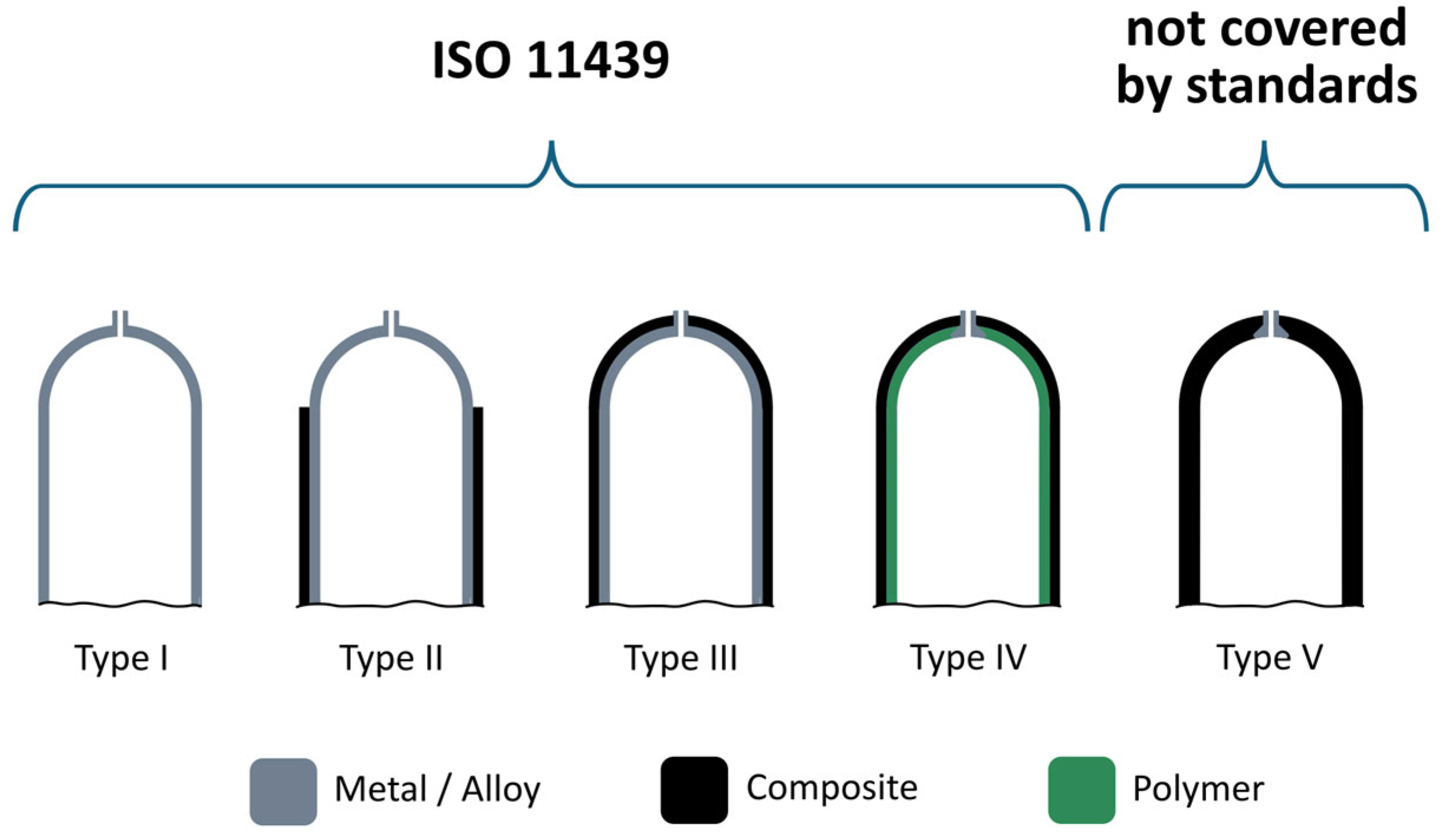
39]. This regulation specifies four principal types of gaseous hydrogen storage vessels permitted for use in mobile applications, classified in ISO 11439 as Type 1 to Type 4 vessels [
40]. Each type differs in terms of the materials used and its structural configuration, which influences the maximum operating pressure, the gravimetric and volumetric hydrogen storage densities, and the safety parameters required for integration into vehicles. Increasing attention has recently been devoted to next-generation Type 5 vessels, which are characterised by the absence of an internal liner. In these vessels, the composite material simultaneously serves as the gas barrier and the load-bearing structure, thereby reducing the vessel mass and simplifying its construction while maintaining the required mechanical strength and safety [
32,
41]. However, Regulation (EC) No 79/2009 does not permit the use of Type 5 vessels in hydrogen-powered motor vehicles, as this vessel category is not currently covered by any international standard or code. Nevertheless, the Type 5 designation is commonly used in industry and academia as an informal technical classification for the latest generation of pressure vessels [
39]. The differences between the currently permitted Type 1–4 hydrogen storage vessels defined in ISO 11439 and Type 5 vessels are illustrated in
Figure 1.
Seamless metallic vessels (Type I) are manufactured entirely from metal and consist of a metallic body incorporating a neck and, optionally, an end plug. The design and manufacture of this vessel type are relatively straightforward, resulting in comparatively low production costs. Despite their high mass and low gravimetric hydrogen storage capacity of approximately 1 wt.%, Type I vessels remain the most widely used configuration, particularly in industrial applications for hydrogen storage at pressures of up to 30 MPa [
43,
44].
Hoop-wrapped vessels with a seamless metallic liner (Type II) consist of a metallic inner liner, typically made of aluminium, reinforced by an external composite overwrap that enhances its mechanical strength. This composite reinforcement enables the use of a thinner and lighter inner liner, allowing operating pressures comparable to those of Type I vessels to be achieved at a lower overall vessel mass. Consequently, Type II vessels offer improved gravimetric efficiency and greater suitability for mobile applications.
Type III vessels are represented by fully wrapped containers with a seamless or welded metallic liner [
45]. In these vessels, the inner metallic liner performs virtually no load-bearing function, as the pressure-induced loads are carried almost entirely by the composite layers wrapped around it. This configuration enables a substantial reduction in the mass of the inner liner.
Type IV vessels are fully wrapped containers with a non-metallic liner. The inner liner is manufactured from a polymeric material and subsequently overwrapped with carbon fibres embedded in a polymer matrix. Owing to their relatively low mass, these vessels are particularly attractive for high-pressure mobile and aerospace applications [
46,
47]. Among the vessel types discussed above, Type III and Type IV vessels are currently the most widely used in the automotive industry because of their low weight and ability to store hydrogen at pressures of up to 70 MPa [
48,
49].
In addition to weight considerations, the vessel design had to account for the need for effective thermal management and cooling associated with the use of an MH alloy. The proposed vessel therefore consists of two concentric components separated by an annular space through which a heat-transfer fluid circulates. The primary vessel has an outer diameter of 159 mm and contains the MH alloy, which enables the absorption of gaseous hydrogen. The outer shell provides mechanical protection and simultaneously forms the annular flow channel for the heat-transfer fluid, thereby enhancing heat transfer during hydrogen absorption and desorption.
Despite its higher mass compared with carbon-fibre-reinforced polymer (CFRP), stainless steel grade 1.4404/316L was selected for both components of the storage vessel because its use is prescribed by the applicable standard and because it exhibits a higher thermal conductivity than CFRP [
50,
51]. Accordingly, the proposed storage vessel is classified as a Type I vessel. The mechanical properties of the stainless steel used are summarised in
Table 1.
The structural design of the low-pressure hydrogen storage vessel is based on the STN EN 13322-2 standard, which addresses transportable gas cylinders and the design and manufacture of refillable welded steel vessels for gas storage [
52]. The standard specifies requirements concerning the design, materials, manufacturing processes, and testing of stainless-steel vessels with a maximum tensile strength of 1100 MPa and a water capacity ranging from 0.5 to 150 L. It further stipulates that the vessel or its individual components must be manufactured from longitudinally welded or seamless tubes. In the proposed design, a seamless tube was selected for the cylindrical section of the primary vessel. The required wall thickness of the primary vessel was determined using Equation (1) [
52]:
where
is the outer diameter of the vessel (mm);
is stress-reduction factor (–);
is design stress factor (–);
is design yield strength of the used material (MPa);
is hydraulic test pressure (MPa).
As a butt-welded end closure was considered in the vessel design, the stress-reduction factor was set to ( = 1) in accordance with Annex A of the standard. The design stress factor prescribed by the standard is ( = 0.77). For the calculation of the minimum wall thickness, the design yield strength is limited to a maximum value of . Accordingly, the design yield strength was determined to be MPa.
The actual hydraulic test pressure was determined using a safety margin of 9.5% above the minimum value prescribed by the standard, corresponding to 1.43 times the operating pressure.
STN EN 13322-2 specifies two types of vessel heads: torispherical and ellipsoidal heads [
52]. Ellipsoidal heads exhibit greater resistance to local buckling in the transition region than equivalent torispherical heads [
53]. Therefore, considering the planned small-series production of the MH storage vessel, an ellipsoidal head was selected despite its greater manufacturing complexity.
The calculated wall thickness of the ellipsoidal vessel head:
where
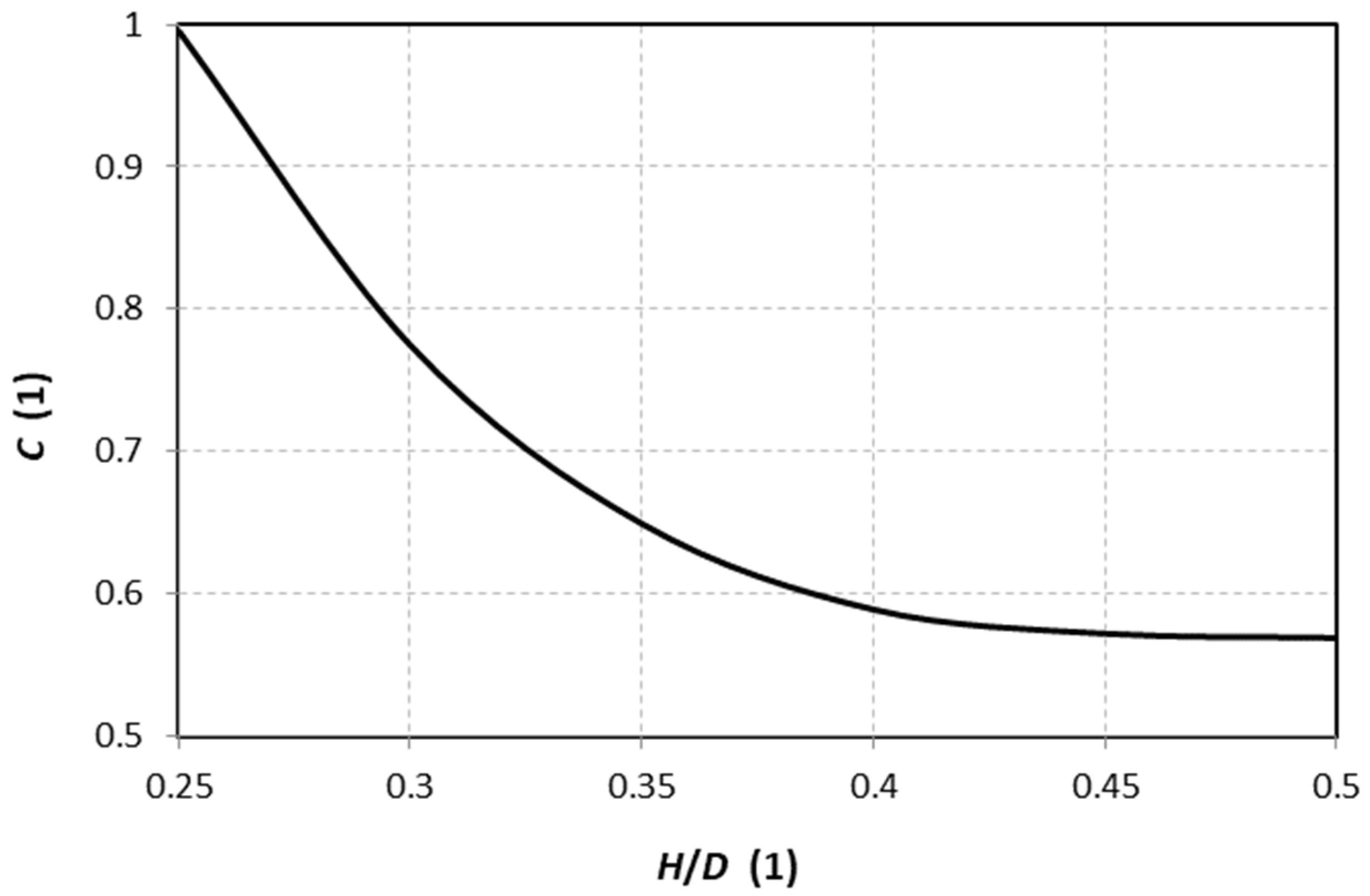
is the shape-factor (–), whose dependence on the ratio of the external height of the dished portion of the head
to the outer diameter of the primary vessel
is shown in
Figure 2.
Furthermore, for a primary vessel with a diameter exceeding 150 mm, the selected wall and head thicknesses must satisfy the conditions defined by Equations (3) and (4).
where
is the minimum wall thickness of the cylindrical vessel section (mm);
—minimum wall thickness of the ellipsoidal vessel head (mm).
By substitution into Equation (3), it is found that ; ≥ 1.324 mm; however, the condition defined by Equation (4) must also be satisfied. Therefore, the selected wall thicknesses of both the cylindrical section and the vessel head must not be less than 1.5 mm.
The outer casing is not subjected to the pressure acting on the inner primary vessel and is therefore considered an auxiliary component of the storage system. According to STN EN 13322-2, the casing material must be compatible with that of the primary vessel. Unlike the primary vessel, the individual casing components may be manufactured using longitudinal welds. However, each auxiliary component must be designed and manufactured to permit inspection of the welded joints [
52]. In the casing design, flanges were used instead of vessel heads to close the assembly, with their inner diameter corresponding to the outer diameter of the primary vessel.
Before performing the structural simulations and manufacturing the prototype, the individual vessel designs were analysed and compared as a function of operating pressure. The principal parameters of the analysed storage vessels are summarised in
Table 2.
Selected parameters of
and
were identical for all three vessel variants. The actual wall thickness
and vessel-head thickness
were selected based on the calculated values of
and
, respectively, multiplied by the corresponding safety factors. Based on the selected parameters, three vessel models were developed for the required operating pressures. Their principal parameters are presented in
Table 3.
The amount of stored hydrogen was calculated for Hydralloy
® C5, an alloy with the composition Ti
0.95Zr
0.05Mn
1.46V
0.45Fe
0.09 [
54]. A key parameter in determining the hydrogen storage capacity of the selected MH alloy is its bulk density, which is approximately
ρMH ≈ 3500 kg·m
−3. Based on the pressure–composition isotherm (PCI) of the selected MH alloy, the hydrogen storage capacity was determined at operating pressures of 3, 5, and 7 MPa and an absorption temperature of 50 °C [
55]. The hydrogen storage capacity was 1.52 wt.% at 3 MPa, approximately 1.65 wt.% at 5 MPa, and approximately 1.68 wt.% at 7 MPa. As can be seen from the PCI curves of the Hydralloy C5 alloy, the most significant increase in hydrogen storage capacity occurs when the pressure is increased within the range of approximately 2 to 3 MPa. Further increases in hydrogen pressure result in progressively smaller gains in hydrogen capacity. Consequently, beyond a certain pressure level, operating the storage tank at higher hydrogen pressures becomes increasingly inefficient.
In addition to the gravimetric hydrogen storage capacity of the alloy, the total amount of stored hydrogen is determined by the overall mass of the MH alloy used. For fixed external vessel dimensions, the quantity of MH alloy that can be accommodated in each vessel variant depends on the wall thickness. Moreover, the density of 316L stainless steel is higher than the bulk density of the MH alloy. Consequently, the use of thicker vessel walls increases the total mass of the storage system despite the reduced quantity of MH alloy contained within it.
The calculated data indicate that the ratio of stored hydrogen mass to the total mass of the storage vessel is approximately 1%, with negligible differences among the individual design variants. In view of these findings, the vessel design with an operating pressure of up to 3 MPa was selected for manufacture and further testing, in order to maintain the lowest possible operating pressure while preserving nearly the same hydrogen storage capacity of the MH storage tank.
3. Structural Verification of the Proposed MH Storage Vessel
A numerical approach based on the finite element method was employed to evaluate the structural performance of the proposed MH storage vessel. It is important to note that numerical simulation serves merely as a self-consistency check based on standard calculations, without comparison against experimental results. The operating temperature of the MH alloy was assumed to have no significant effect on the mechanical strength of the vessel because the considered temperature range does not produce significant changes in the material properties of 316L stainless steel. The finite element mesh comprised approximately 250,000 quadratic solid elements and 600,000 nodes. The constrained surface had a width of 20 mm and extended circumferentially around the MH storage vessel. At the valve end, radial and axial displacements were constrained, whereas at the closed end, only radial displacement was restricted. The numerical model was subjected to an internal pressure corresponding to the maximum hydraulic test pressure of 4.7 MPa. The mechanical loading induced by the powdered alloy inside the vessel was also considered. The powder bed was represented by an equivalent hydrostatic pressure exerted by a fictitious fluid with the same density as the MH alloy.
After applying all boundary conditions, the model was pressurised and subsequently depressurised to 0 MPa, completing one loading cycle. Analysis of this cycle provided the residual stress and strain values.
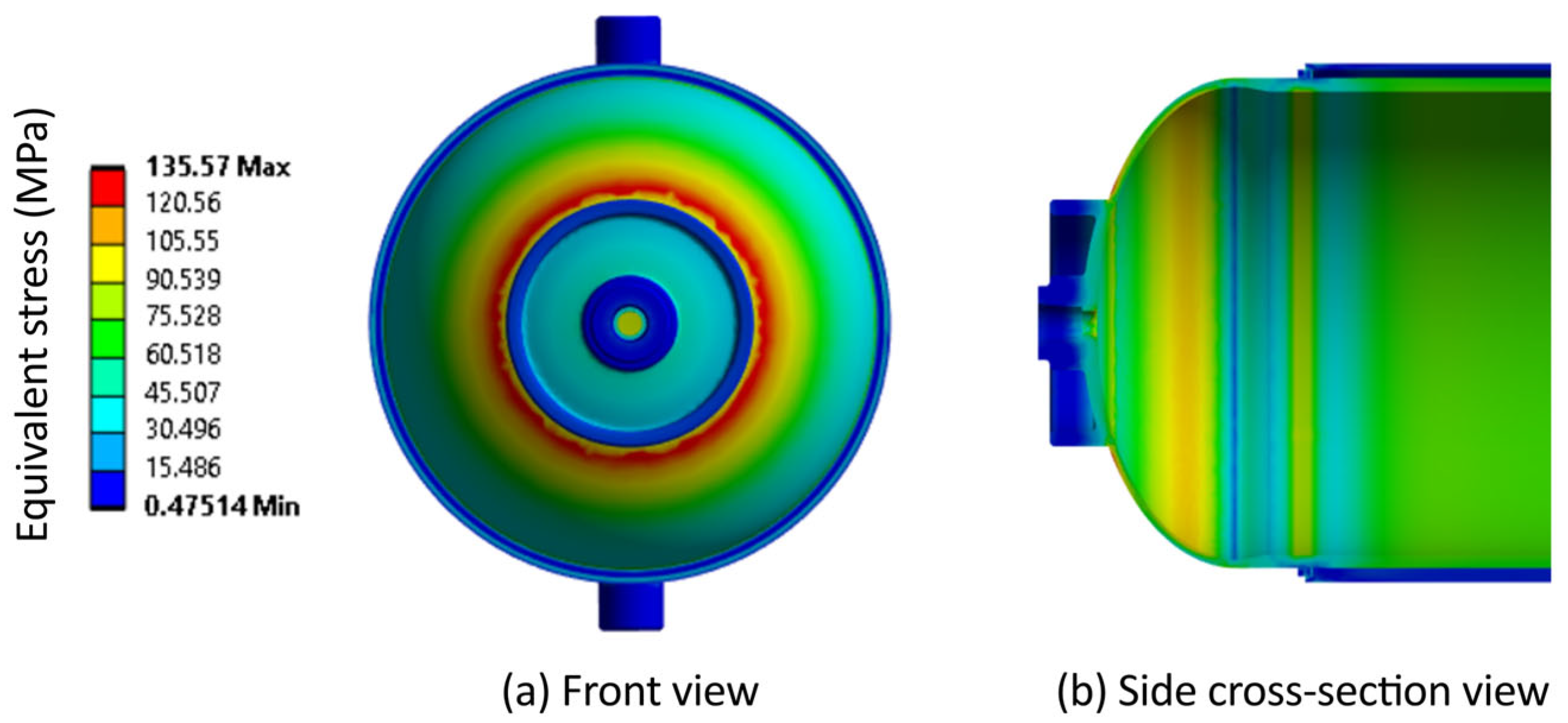
Figure 3 presents the structural simulation results obtained at the maximum hydraulic test pressure.
The structural simulation results for the MH storage vessel under maximum loading are presented in
Table 4.
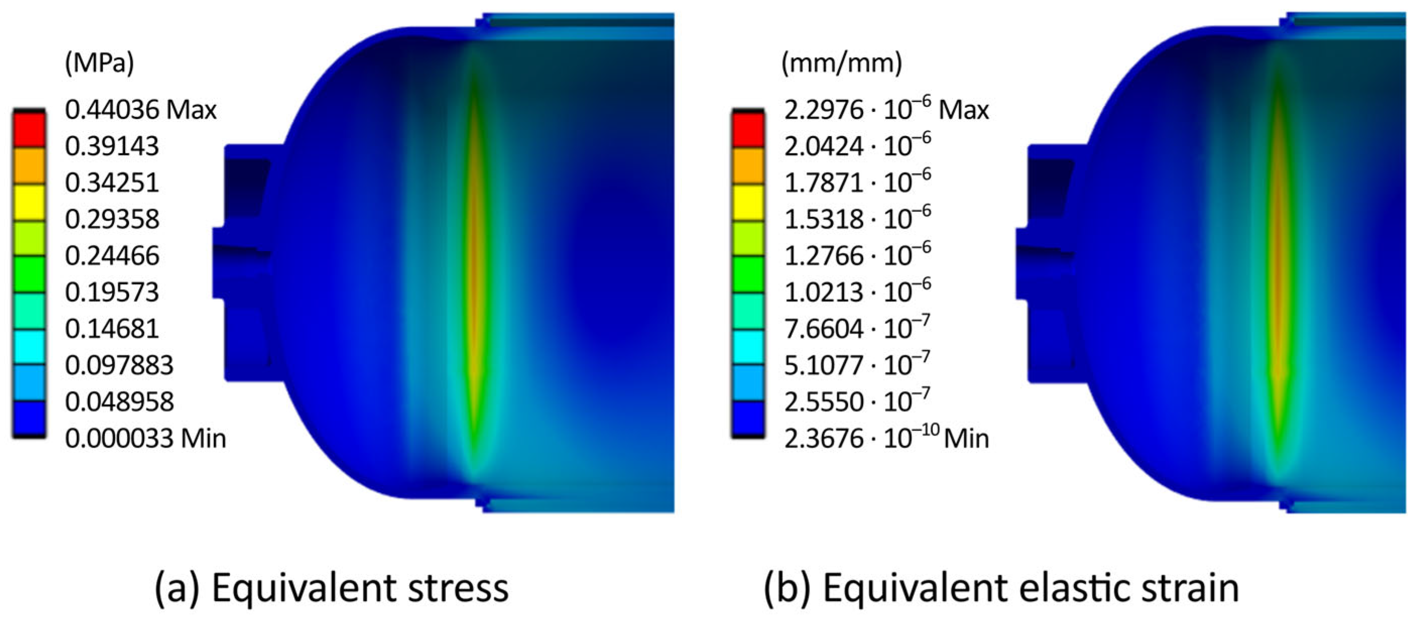
Figure 4 shows the residual stress and strain distributions after unloading of the MH storage vessel. The highest residual stress concentrations occur at the welded joint between the primary vessel and the ellipsoidal head.
The structural simulation results obtained after unloading of the MH storage vessel showed that the total displacements were zero, indicating that no plastic deformation occurred. The von Mises equivalent stress distribution revealed that the residual stresses reached only 0.44 MPa, while the vessel strain
ε was only 2.2976 · 10
−6. Based on these results, a stress–strain curve can be constructed and expressed by Equation (5), with a correlation coefficient of R
2 = 1:
To analytically verify the simulated displacement and strain results for the MH storage vessel, the fundamental theory of elasticity and strength of materials for thin-walled pressure vessels was applied. A vessel is considered thin-walled when the ratio of the primary-vessel radius r to its wall thickness b is greater than 10. The cylindrical section of the primary vessel has a radius of 79.5 mm and a wall thickness of 4.5 mm.
The resulting ratio is 17.6, confirming that the proposed storage vessel can be treated as a thin-walled pressure vessel. Its structural characteristics can therefore be evaluated using the corresponding thin-walled vessel relationships. In thin-walled pressure vessels, axial stress
and circumferential stress
are generated, whereas the radial stress is assumed to be negligible [
56]. These stresses can be calculated using the following equations:
Substitution into Equations (6) and (7) yielded an axial stress of 41.516 MPa and a circumferential stress of 83.03 MPa. The maximum shear stress
can be determined from Mohr’s circle as its radius and was found to be 41.516 MPa. The von Mises equivalent stress can be calculated using the following Equation (8) [
57]:
Substitution of the stress values into Equation (8) yielded a von Mises equivalent stress of 71.9 MPa. The corresponding value obtained from the numerical simulation was 67.631 MPa, representing a deviation of 6%.
The internal pressure induces circumferential and axial strains in the wall of the cylindrical vessel. In thin-walled pressure vessels, radial strains are very small and are therefore neglected in the calculations. The axial and circumferential strains are determined using the following Equations (9) and (10) derived from Hooke’s law [
58]:
Substitution into Equations (9) and (10) yielded an axial strain of 0.0138% and a circumferential strain of 0.0484%. To determine the corresponding dimensional deformation, the increase in the outer radius of the vessel
r, caused by the internal pressure, must be calculated. The change in the outer circumference of the cylindrical section of the primary vessel can be determined from the circumferential strain, as this quantity represents the ratio of the change in circumference to the original circumference. The change in circumference can subsequently be expressed and substituted into the relationship for the radial expansion
. After rearrangement, Equation (11) for calculating the change in radius takes the following form:
The analytically calculated change in radius = 0.027 mm corresponds to the total deformation of the cylindrical section of the primary vessel. The total deformation obtained from the numerical simulation was 0.0275 mm, representing a deviation of approximately 1.9% from the analytical result.
4. Experimental Validation of the Structural Strength of the Storage Vessel
In addition to the structural design requirements, STN EN 13322-2 provides requirements for the fabrication and manufacture of newly designed storage vessels and specifies all tests that the vessel must successfully undergo. The certification programme includes tensile, bend, and impact tests; macroscopic examination of weld cross-sections; hydraulic pressure testing; radiographic, radioscopic, or other non-destructive testing of structural welds; pressure cycling; and corrosion testing. All these tests must be performed on finished vessels after completion of all manufacturing processes, including cold forming at cryogenic temperatures [
52].
A total of three storage vessels were required for the experimental testing. The first vessel was used for mechanical testing, including tensile testing, bend testing, impact testing, and macroscopic examination of the fabricated welds. The second vessel was subjected to a hydraulic burst test, while the third vessel was used for the cyclic pressure test.
4.1. Mechanical Tests
The tensile test must be performed on test specimens extracted from the manufactured vessel in accordance with the requirements of STN EN 10002-1 [
59]. One specimen is taken from the central region of the cylindrical section of the vessel, while the second is extracted from either vessel head. The surfaces of both specimens corresponding to the inner and outer surfaces of the vessel must not be machined. Only specimens taken from the ellipsoidal head may be flattened by cold pressing to allow their proper clamping in the testing machine [
59].
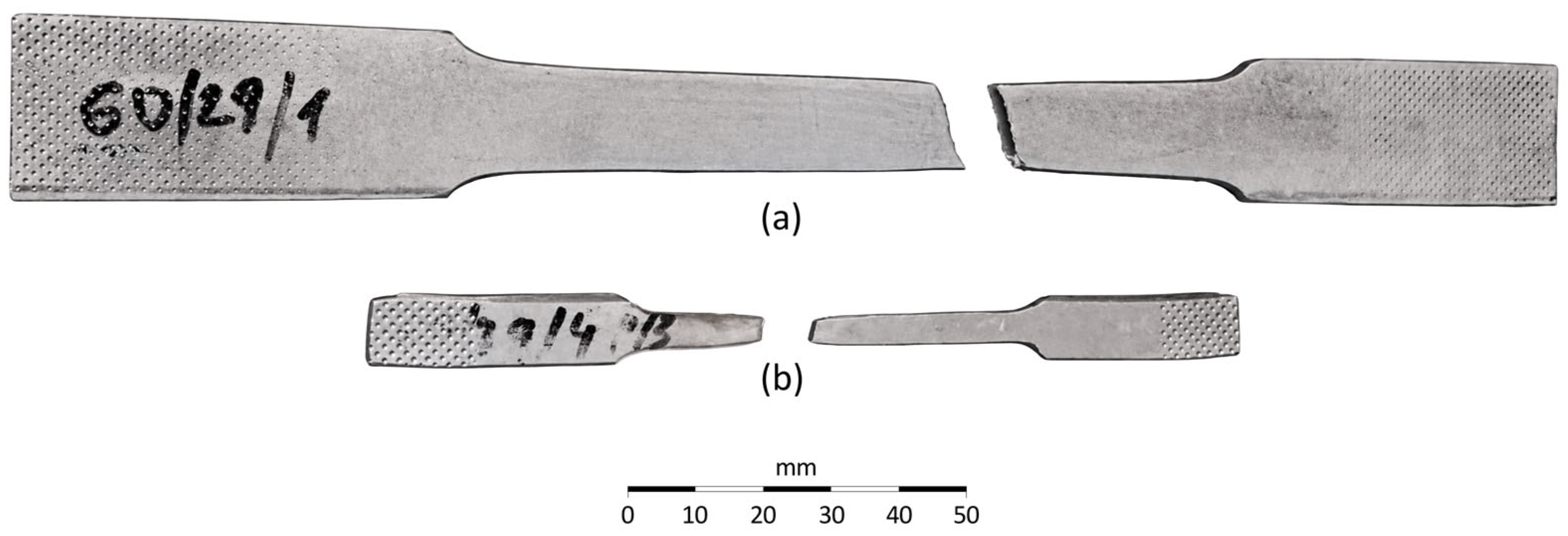
The material properties determined from both specimens, namely the yield strength and ultimate tensile strength, must not be lower than the values specified by the material manufacturer. Under no circumstances may the elongation at fracture be less than 14%. The tested specimens are shown in
Figure 5.
The tensile test results for the specimen extracted from the vessel head and the longitudinal specimen are presented in
Table 5 and
Table 6, respectively.
Tensile testing was subsequently performed on the welded joints of the vessel. One specimen was extracted from each circumferential weld in the vessel structure. No longitudinal welds were present in the primary vessel. The tensile test results for the circumferential welds are presented in
Table 7 and
Table 8.
The impact test is not required when the vessel wall thickness is less than 5 mm, and the test pressure is below 60 bar. Although the proposed storage vessel falls within the category for which impact testing is not mandatory, the test was nevertheless performed for research purposes. The impact test results are presented in
Table 9.
The impact test was performed on the base material; therefore, the results represent the intrinsic material properties without any influence from welding. Testing was conducted under liquid-nitrogen conditions, at which most conventional structural steels exhibit a substantial loss of toughness. The measured mean impact energy represents an exceptionally high value, confirming the material’s ability to absorb severe impact loads.
4.2. Hydraulic Burst Test
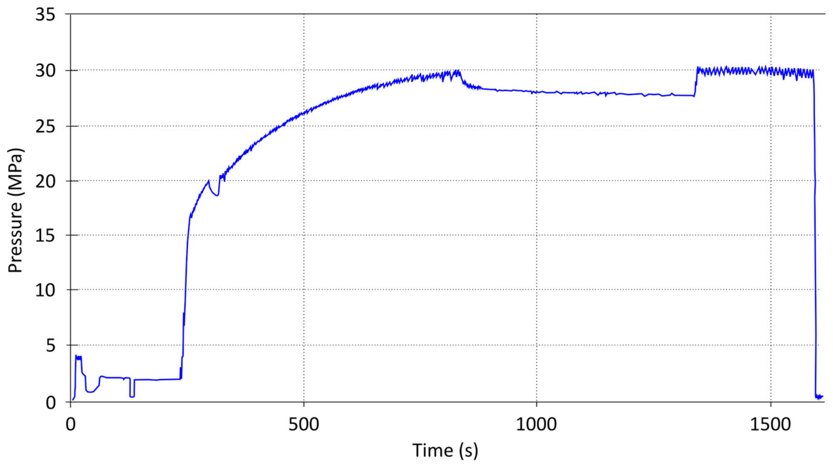
The hydraulic burst test of the proposed storage vessel must be performed using equipment that enables the pressure to be increased at a manually adjustable rate until failure of the test vessel occurs. During the test, the pressure variation as a function of time was recorded, as shown in
Figure 6.
For a test pressure of 6 MPa or less, the burst pressure must be at least 2.25 times the hydraulic test pressure above atmospheric pressure. Accordingly, the minimum required burst pressure is 10.575 MPa. During the burst test, no fragmentation of the vessel material is permitted. The principal fracture resulting from the pressure test must exhibit no signs of brittle failure; specifically, the fracture edges must not be radial, must show a reduction in wall thickness, and must be inclined relative to the diametral plane. If the resulting fracture does not satisfy these requirements, the vessel must be submitted for further testing to determine whether it should be accepted or rejected. As shown in
Figure 6, the storage tank failed at a pressure of approximately 30 MPa, corresponding to ten times its maximum operating pressure. The slight pressure drop observed between approximately 800 and 1300 s resulted from replenishment of the test liquid during the pressure test.
4.3. Cyclic Pressure Test
The cyclic pressure test was performed on one manufactured storage vessel in accordance with STN EN 13322-2, using water as the test medium. Successful completion of the test requires a minimum of 12,000 pressure cycles without the occurrence of any leakage or structural failure [
52]. Owing to the large number of cycles, the test was conducted over three consecutive days using the parameters specified in
Table 10.
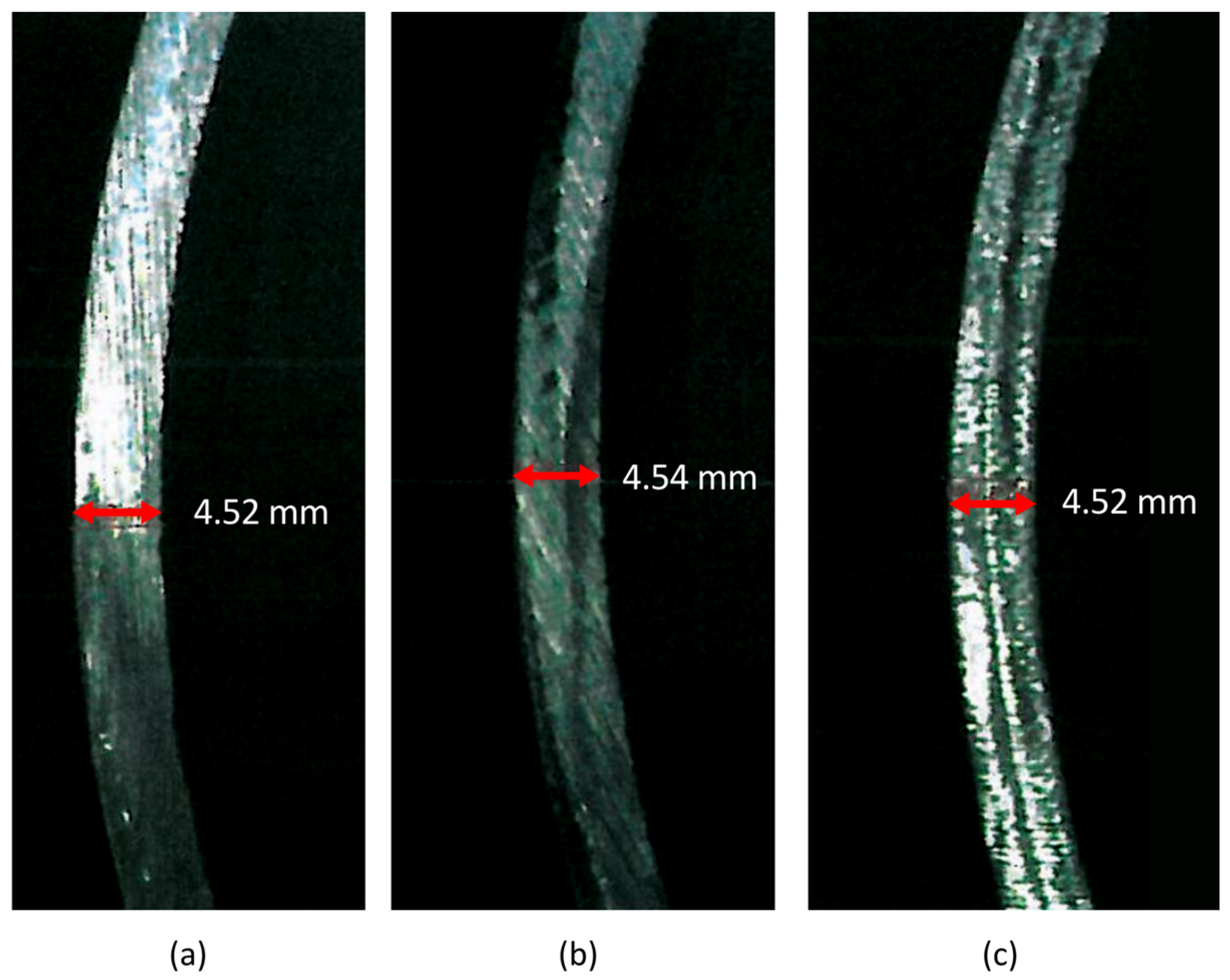
Following completion of the cyclic pressure test, the storage vessel was sectioned into several pieces to enable measurement of the vessel wall thickness and to verify that the measured thickness did not exceed the minimum required thickness by more than 15% (
Figure 7).
5. Design of the Internal Passive Cooling Element and Its Effect on the Temperature Field During Hydrogen Absorption
Hydrogen absorption into the metal structure is an exothermic process. Heat is generated as a result of hydrogen-molecule dissociation and the subsequent diffusion of hydrogen atoms into the interstitial sites of the crystal lattice; this heat must be efficiently removed from the alloy. Appropriate thermal management is therefore required to achieve and maintain optimal temperature and pressure conditions during operation of the storage vessel.
The proposed MH storage vessel incorporates both passive and active cooling elements. The active cooling element is provided by a coolant flowing through the annular space between the primary vessel and the outer casing, whereas the passive cooling element is located inside the primary vessel. A 1 mm gap is maintained between the inner wall of the primary vessel and the passive cooling element. Because the passive cooling element is not permanently joined to the primary MH vessel and does not perform a load-bearing function, aluminium was selected as its material owing to its low mass and high thermal conductivity of 237 W·m−1·K−1.
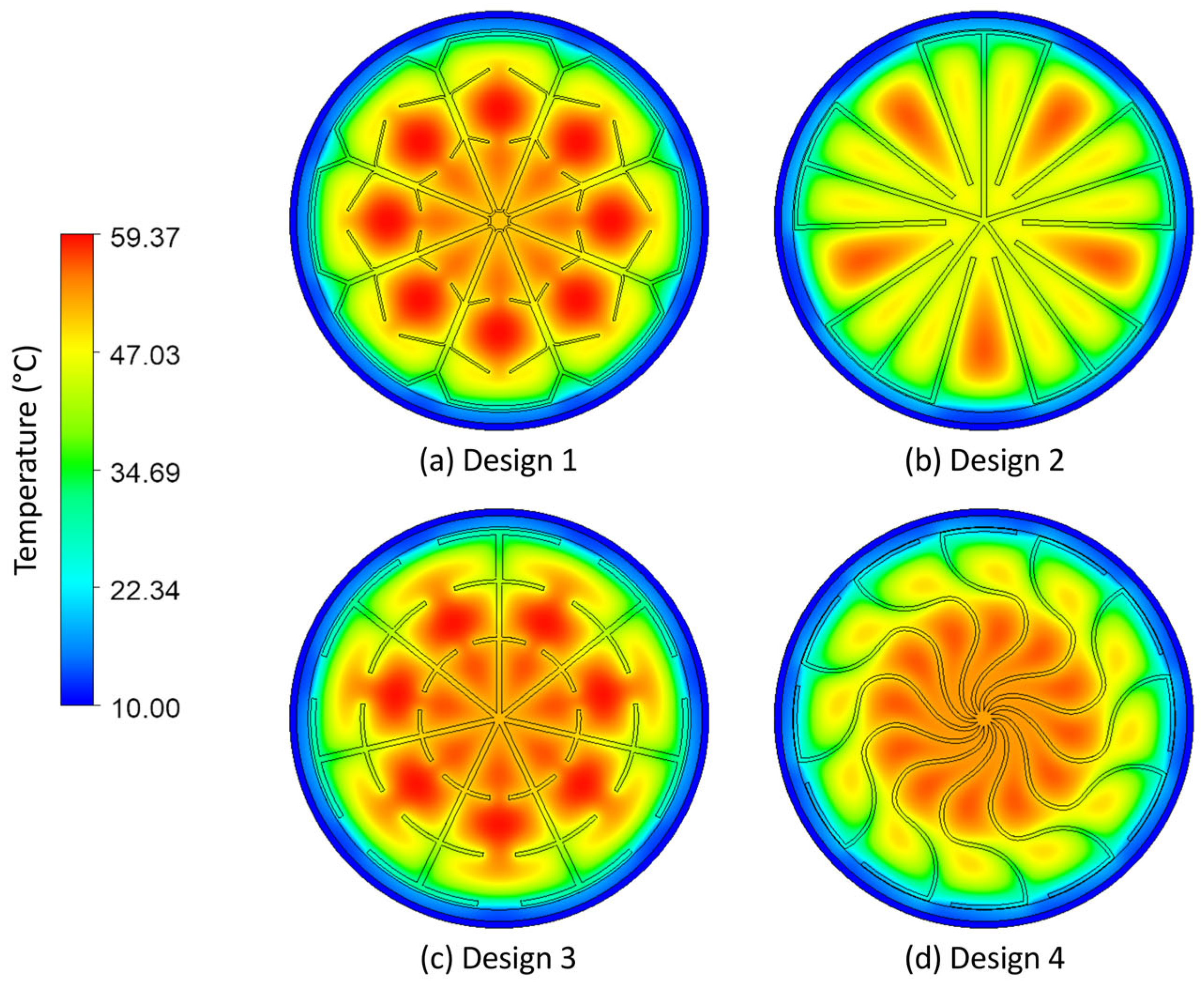
Four different geometries of the passive cooling element were analysed (
Figure 8). The objective was to achieve the most uniform temperature distribution possible while simultaneously minimising the temperature of the MH alloy during a simulated 30 min hydrogen absorption process. For an MH alloy mass of 50.07 kg and a gravimetric hydrogen storage capacity of 1.52 wt.%, the corresponding hydrogen volume is approximately 9.17 m
3. The absorption of this amount of hydrogen generates approximately 9.26 MJ of heat. Considering the absorption time and the vessel volume, the volumetric heat-generation rate within the storage vessel was determined to be 367,457.29 W·m
−3. The coolant temperature was set to 10 °C, while the initial temperature of the MH alloy was defined as 20 °C. For all designs, the cross-sectional area of the passive cooling element was maintained at 2277.13 ± 11.54 mm
2, corresponding to a relative standard deviation of 0.507% (
Table 11).
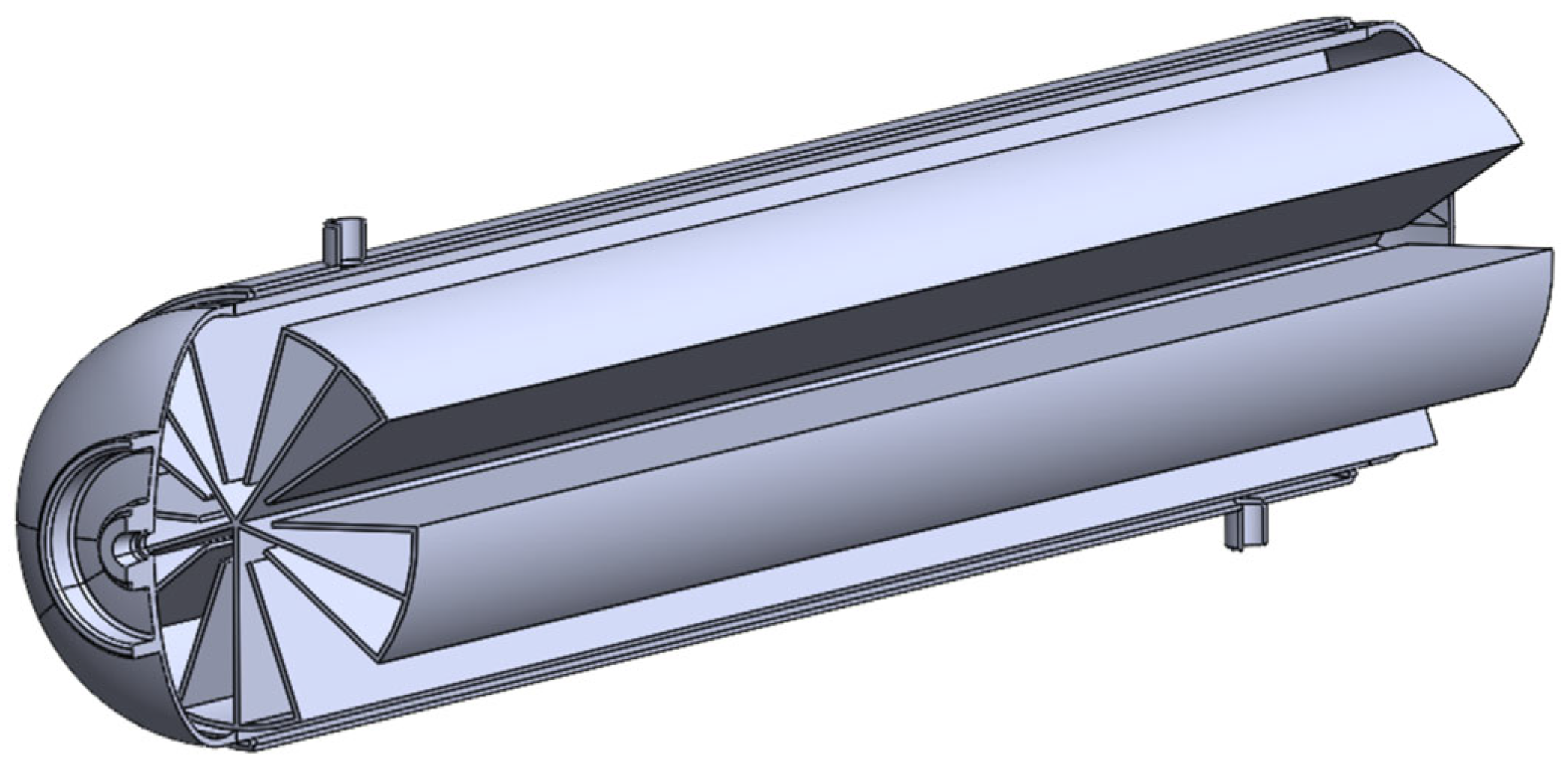
Among the proposed geometries, Design 2 exhibited the highest cooling effectiveness, referring to the lowest average temperature, while also being relatively simple to manufacture compared with the other designs. It was therefore selected for the subsequent stages of the study. The proposed passive cooling element consists of five primary fins and ten secondary fins. The primary and secondary fins are joined by curved connecting elements that follow the internal curvature of the storage vessel (
Figure 9).
After selecting the most effective geometry from among the analysed passive cooling-element variants, the element was manufactured, and the experimental data obtained during hydrogen absorption were subsequently compared with the numerical simulation results. Accurate specification of the internal heat source within the storage vessel is essential for calculating the temperature field. The heat of absorption of Hydralloy C5 associated with the absorption of 1 m
3 of hydrogen is 1.01 · 10
6 J∙m
−3. Although the hydrogen flow rate was recorded during the experiment, the measured values did not directly correspond to the amount of hydrogen absorbed by the alloy. This discrepancy arises because the gradual increase in temperature causes the equilibrium pressure to rise during hydrogen absorption. The resulting pressure increase leads to an increase in the mass of hydrogen present in the free volume of the system. A positive pressure change therefore produces a positive change in the mass of gaseous hydrogen and, consequently, in its equivalent volume under normal conditions. Thus, the measured volumetric hydrogen flow rate differs from the actual hydrogen absorption rate by the time-dependent elementary change d
τ in the volume of hydrogen, expressed under normal conditions, stored in the free volume between the alloy particles d
VFV,n. The modified internal heat source
was therefore determined from the experimental data using the following Equation (12) [
60]:
where
is the heat released during hydrogen absorption (J·m
−3);
is the measured volumetric hydrogen flow rate (m
3·s
−1);
is the change in vessel pressure during hydrogen absorption (Pa);
is the thermodynamic temperature under normal conditions, equal to 273.15 K;
is the mean thermodynamic temperature of the storage vessel (K);
is the pressure under normal conditions, equal to 101,325 Pa.
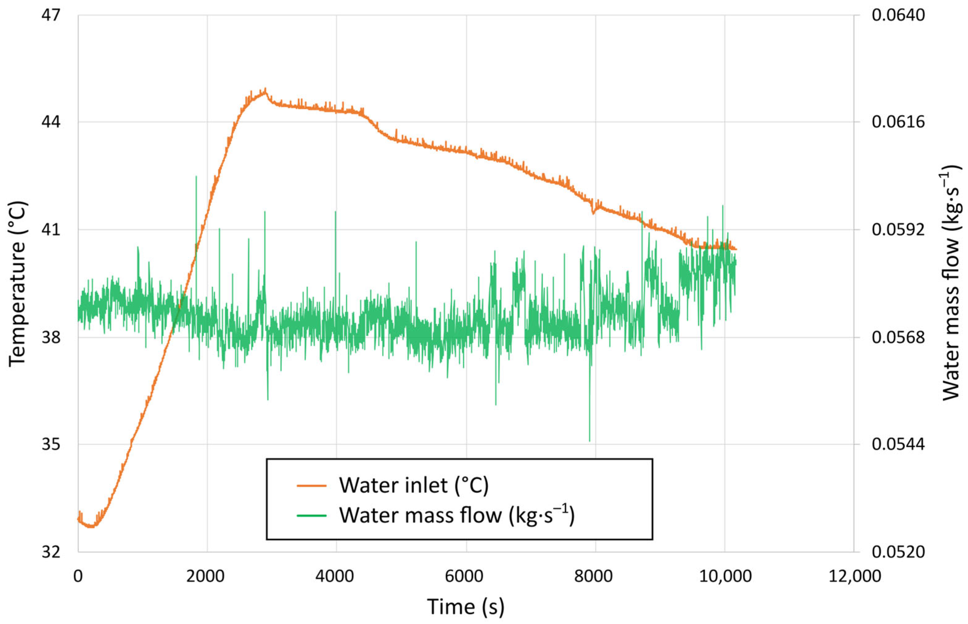
The water mass flow rate recorded by the flow metre during the experiment was used as an input parameter for the simulation, together with the water temperature at the storage vessel inlet (
Figure 10).
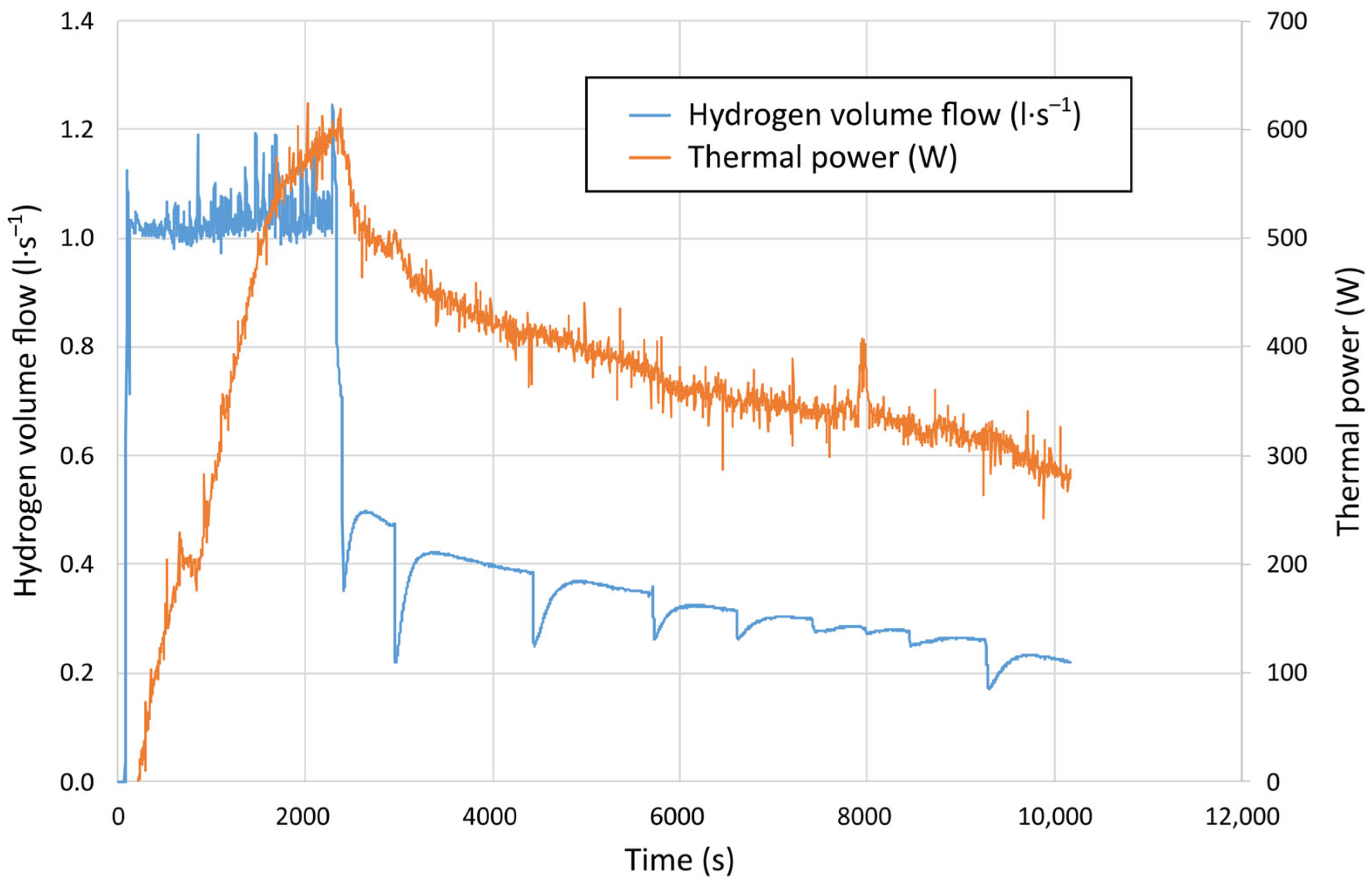
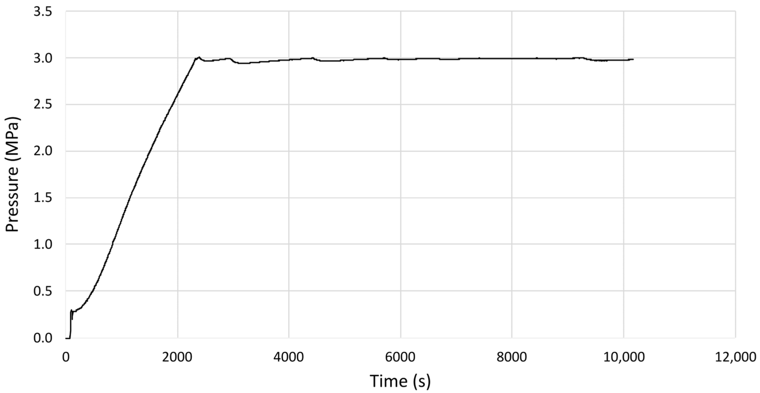
Other parameters monitored during the experiment included the hydrogen flow rate into the storage vessel (
Figure 11) and the hydrogen pressure within the vessel (
Figure 12). During hydrogen absorption, the pressure was maintained below the maximum operating pressure of the proposed MH storage vessel, i.e., 3 MPa. The thermal power transferred from the storage vessel can also be determined from the coolant mass flow rate, specific heat capacity, and temperature difference between the cooling-water outlet and inlet (
Figure 11):
where
is water mass flow rate (kg·s
−1);
is the specific heat capacity of water (J·kg
−1·K
−1);
is the water temperature at the outlet (°C);
is the water temperature at the inlet (°C).
This relationship is valid provided that the water absorbs heat only from the storage vessel and not from the surroundings. Therefore, during the experiment, the vessel was insulated with a 10 mm thick elastomeric insulation layer covered with aluminium foil. In calculating the thermal power, the temperature dependence of the specific heat capacity of water was taken into account using an appropriate function, since the water temperature varied throughout the experiment. The calculations were based on the mean water temperature, determined as the average of the inlet and outlet temperatures.
A tetrahedral computational mesh was generated with respect to the dimensions of the individual domains. Mesh refinement in regions where boundary layer development was expected was achieved using the inflation function. After defining the material properties, a boundary condition representing the overall heat transfer coefficient
k from the inner surface of the steel shell to the ambient environment was applied according to the following:
where
is the steel wall thickness of the tank (m);
is the thermal conductivity coefficient of steel (W·m
−1·K
−1);
is the thickness of rubber insulation (m);
is the thermal conductivity coefficient of rubber (W·m
−1·K
−1);
is the convective heat transfer coefficient (W·m
−2·K
−1).
Considering the 10 mm thick rubber insulation layer and, in particular, its significantly lower thermal conductivity = 0.037 W·m−1·K−1 compared with that of the steel shell, the thermal resistance of the steel wall can be neglected when determining the overall heat transfer coefficient. The convective heat transfer coefficient = 5.1 W·m−2·K−1 was estimated using empirical heat transfer correlations based on experimentally measured data, assuming an outer insulation surface temperature of 40 °C and an ambient air temperature of 22 °C. Since the rubber insulation was covered with a thin aluminium foil, thermal radiation was also taken into account using an emissivity of = 0.15. Substituting into Equation 14 yielded an overall heat transfer coefficient of = 2.14 W·m−2·K−1.
A medium turbulence intensity of 5% was prescribed at the cooling water inlet. At the outlet, an average static pressure of 0 Pa was specified to represent unrestricted outflow of the coolant. The pressure profile blend parameter was set to 0.05, meaning that the average static pressure over the entire outlet cross-section was maintained at 0 Pa, while local pressure deviations of up to ±5% were permitted. A transient analysis was performed, with the total simulation time corresponding to the duration of the experimental measurement. The convergence criterion for the numerical solution was set to a residual target of 1 · 10−6.
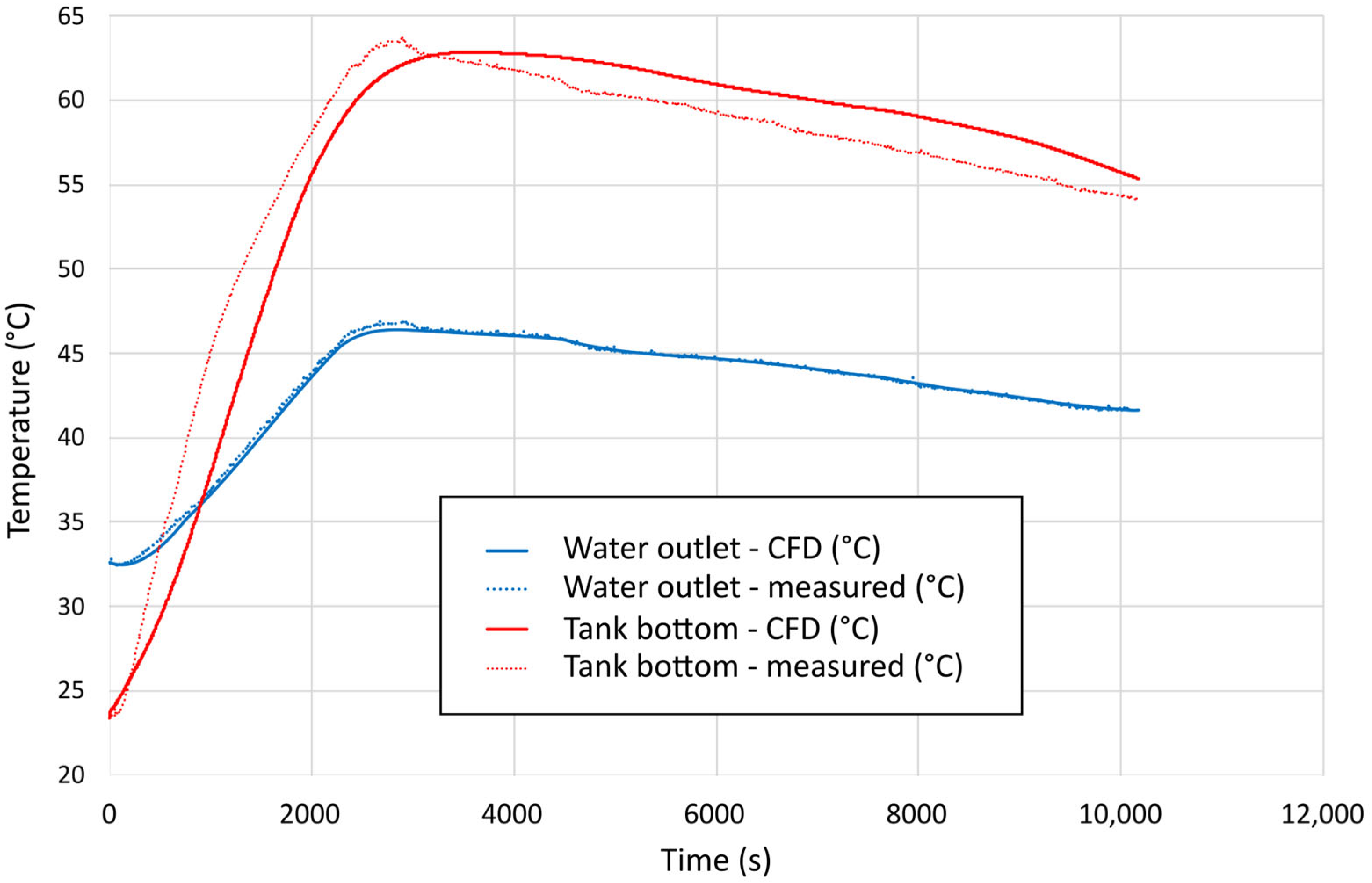
Because the detailed temperature distribution within the storage vessel could not be determined directly from the experimental data owing to the absence of internal temperature sensors, the simulation results could not be compared directly with the actual temperature field inside the vessel. The simulation was therefore validated by comparing the experimentally measured cooling-water outlet temperature and the vessel-surface temperature at a specific point on the vessel head with the corresponding values obtained from the numerical simulation (
Figure 13).
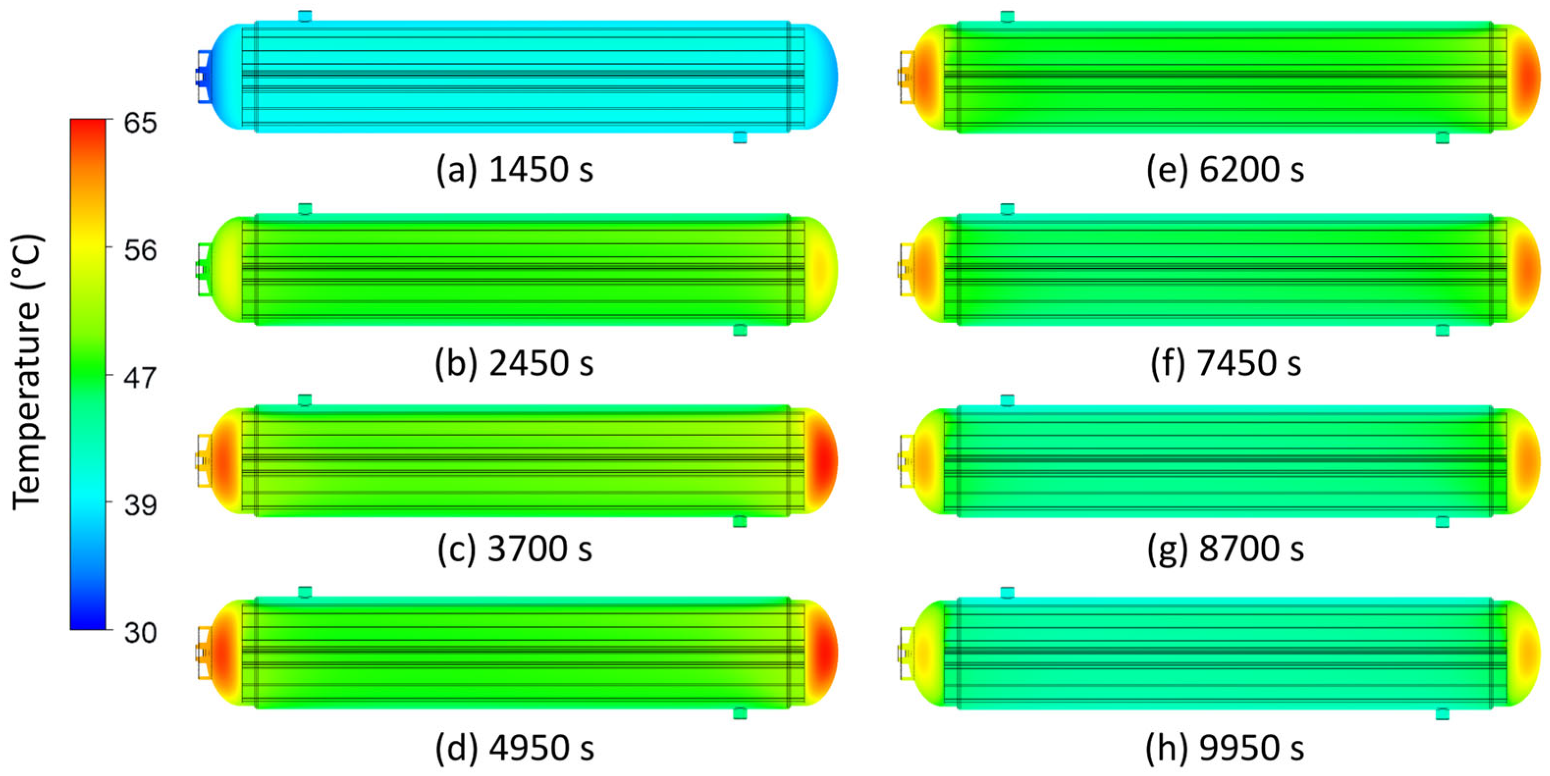
The temperature distribution within the MH storage vessel during hydrogen absorption, obtained by numerical simulation for a longitudinal section through the vessel axis, is shown in
Figure 14. The temperature field indicates local overheating in the bottom region of the vessel, caused by the design of the passive and active cooling elements.
Although the elevated temperatures predicted in the dished-end regions are relatively localised, the resulting thermal gradients may induce additional thermo-mechanical stresses in the vicinity of the circumferential welds during repeated hydrogen absorption/desorption cycles. Evaluation of these effects requires coupled thermo-mechanical analysis and is considered a subject for future research.
6. Discussion
The structural design of the MH storage vessel was developed in accordance with STN EN 13322-2, which specifies requirements for the design, strength calculation, testing, and certification procedures for pressure equipment intended for gas storage. A verification strength calculation performed in accordance with this standard was used to determine the optimal characteristic dimensions of the vessel while accounting for the operating loads and the material safety limits.
An operating pressure of 3 MPa was adopted for the vessel because the individual design variants exhibited only negligible differences in the gravimetric hydrogen storage capacity while maintaining the same external vessel dimensions. The numerical structural analysis confirmed that the proposed design satisfies the required operating conditions. The von Mises equivalent stress field at both the operating pressure of 3 MPa and the maximum test pressure remained below the yield strength of the selected material, thereby ensuring the mechanical safety of the vessel. The subsequent analytical strength calculation for the cylindrical section of the primary vessel showed only minor deviations from the numerical solution, amounting to 6% for the equivalent-stress analysis and 1.9% for the total-deformation analysis.
The tensile tests performed during the experimental investigation showed that the actual tensile strength of the material exceeded the manufacturer-guaranteed value for both the longitudinal specimen and the specimen extracted from the vessel head. Following the impact bend tests, the specimens exhibited no evidence of brittle fracture, indicating good material toughness. The weld specimens subjected to fracture testing showed no cracks or other defects, confirming the quality of the welded joints and their reliability under operating loads. During the hydraulic burst test, the vessel failed after 1090 s at a pressure of 29.4 MPa, corresponding to almost ten times its normal operating pressure. The failure occurred 20.5 mm from the top of the vessel and extended over a length of 39.7 mm. The resulting fracture was ductile in nature. Based on these findings, the proposed vessel was considered to satisfy the hydraulic-test requirements of STN EN 13322-2. The cyclic pressure test demonstrated that the vessel withstood more than 12,000 cycles without leakage or structural changes to the vessel shell. The maximum change in vessel wall thickness was 0.89%, which is well below the prescribed limit of 15% specified in STN EN 13322-2.
Based on the analytical calculations, numerical simulations, and mechanical-test results, it can be concluded that the proposed MH storage-vessel design satisfies the required operating and safety criteria, thereby confirming the suitability of the proposed solution for practical implementation in hydrogen energy systems.
The proposed MH storage vessel also incorporates a heat-transfer enhancement element in the form of a passive cooling module located inside the primary pressure vessel. This component facilitates the efficient removal of heat generated during the exothermic absorption of hydrogen by the MH. Before the final geometry of the enhancement element was manufactured, the temperature-field distribution was numerically analysed for four different designs with similar cross-sectional areas. The most effective design consists of five primary fins and ten secondary fins, which conduct heat from the central region of the vessel towards its inner wall. From there, the heat is removed by the coolant flowing around the outer surface of the primary vessel.
After the passive cooling element had been manufactured, the storage vessel was subjected to experimental testing during hydrogen absorption. The resulting data were subsequently used to validate a CFD simulation for determining the temperature distribution within the MH storage vessel. The maximum temperature reached within the MH storage vessel was approximately 62.5 °C. The temperature field revealed localised regions of elevated temperature near the vessel heads compared with the remainder of the vessel. This temperature non-uniformity was caused by the design of the passive and active cooling elements, neither of which physically extends into the vessel-head regions. One possible partial solution that would not require modification of the active cooling element is to extend the heat-transfer enhancement element while accounting for the curved geometry of the vessel head.
Based on the data obtained during the experiment, the thermal power of the storage vessel could be estimated. The experiment was conducted at a mean coolant inlet temperature of 41.5 °C. These operating conditions were determined by the limited cooling capacity of the laboratory cooling unit. The restricted removal of heat released during the exothermic absorption process caused the temperature of the hydride bed to increase, thereby reducing the absorption kinetics and prolonging the overall process. Consequently, the measured absorption time cannot be interpreted as the characteristic minimum filling time of the storage vessel or directly compared with the results of systems equipped with more effective thermal management. Moreover, the total amount of hydrogen absorbed, 0.44 kg over 10,100 s, does not represent the maximum hydrogen storage capacity of the vessel. A comparison with similar studies is presented in
Table 12.
Kumar et al. analysed a storage vessel containing 40 kg of alloy LaNi
4.7Al
0.3, cooled by 99 internal tubes [
61]. During the final activation cycle, the vessel absorbed 0.552 kg at a filling pressure of 4 MPa and a flow rate of 30 L·min
−1; approximately 6 MJ of heat was removed over 500 s, corresponding to an average cooling power of 12 kW. However, because this was an activation cycle conducted at high pressure, the value serves only as a performance benchmark rather than as the principal basis for operating-condition comparison. Following activation, the authors performed parametric tests at filling pressures ranging from 0.2 to 2.5 MPa. The amount of available hydrogen was limited to approximately 0.425 kg, corresponding to approximately 80% of the maximum storage capacity. At a filling pressure of 1 MPa, the vessel absorbed 0.424870 kg of H
2 in 1253 s, whereas at 1.5 MPa, it absorbed 0.425731 kg of H
2 in 1017 s. The authors identified filling pressures of 1 to 1.5 MPa as a suitable operating range.
Because the total heat removed by the cooling water was not reported for these parametric cycles, the average reaction heat-release rate was estimated from the absorbed hydrogen mass and the absorption enthalpy of the alloy. The resulting values were approximately 4.91 kW at a pressure of 1 MPa and 6.07 kW at a pressure of 1.5 MPa. The average thermal power of approximately 0.364 kW measured on the water side of the proposed storage vessel corresponds numerically to 7.5% and 6.1% of these reaction heat-release rates, respectively. This comparison is only indicative because the thermal power values were determined using different methods.
For the absorption of a comparable absolute amount of hydrogen, the experiment conducted with the proposed storage vessel required approximately 8.1 times longer than the Kumar et al. test at 1 MPa and approximately 9.9 times longer than the test at 1.5 MPa. These results, however, should not be interpreted as a direct comparison of the intrinsic absorption kinetics of the alloys. The tests differed in the type of MH material, heat-exchanger design, cooling-water flow rate, temperature, and pressure conditions. Kumar et al. operated under a constant hydrogen supply pressure, whereas in the experiment with the proposed storage vessel, the dynamic pressure was recorded directly inside the vessel. The pressure conditions therefore cannot be regarded as identical, either in this comparison or in comparisons with the other studies listed in
Table 12.
Gupta et al. experimentally investigated a multi-tube storage vessel containing 50 kg of LaNi
5 alloy [
62]. The MH alloy was distributed among seven tubes, while water flowed across the reactor shell. At a cooling-water inlet temperature of 30 °C, a flow rate of 20 L·min
−1 and a filling pressure of 3 MPa, the vessel reached 90% of its storage capacity within 1286 s. The total hydrogen storage capacity was 0.68 kg. For complete filling, the authors reported an equivalent thermal energy of 10.4 MJ. Assuming an approximately proportional relationship between the fraction of the storage capacity filled and the amount of heat released, the average thermal power up to 90% capacity can be estimated at 7278 W. This value represents a derived reaction heat-release rate rather than the thermal power directly measured on the cooling-water side.
The average thermal power of the proposed storage vessel, 370.1 W, corresponds to approximately 5.1% of the estimated thermal power reported by Gupta et al. The average hydrogen absorption rate in the study by Gupta et al. was approximately 28.6 g·min−1, whereas the proposed storage vessel absorbed hydrogen at an average rate of approximately 2.61 g·min−1. Thus, the average absorption rate of the published reactor was approximately 11 times higher. This substantial difference can be attributed primarily to the more intensive thermal management employed by Gupta et al. The cooling-water flow rate was approximately 5.8 times higher, while the inlet temperature was 11.5 °C lower than that used for the proposed storage vessel. However, a direct comparison of the absorption times is limited because the published value corresponds to 90% of the maximum storage capacity, whereas the experiment with the proposed storage vessel was terminated before its maximum capacity was reached.
Afzal and Sharma experimentally investigated a storage vessel containing 47.5 kg of La
0.9Ce
0.1Ni
5 alloy [
63]. The reactor was equipped with 30 hexagonal heat-transfer elements designed to conduct heat from the core of the MH bed to the outer surface. The authors reported a nominal stored hydrogen mass of approximately 0.667 kg. At filling pressure 3.5 MPa and a cooling-water inlet temperature of 25 °C, the vessel reached 90% of its storage capacity in approximately 4350 s, corresponding to approximately 0.6 kg of absorbed hydrogen. The water was contained in a tank surrounding the reactor, and the cooling process was characterised as natural convection with a heat-transfer coefficient of 1112.898 W·m
−2·K
−1. The authors did not report the volumetric water flow rate.
Using an absorption enthalpy of 25.98 kJ·mol−1 H2 for the La0.9Ce0.1Ni5 alloy, the heat released upon reaching 90% of the storage capacity can be estimated at 7.74 MJ. The corresponding average reaction heat-release rate over 4350 s is approximately 1.78 kW. The average thermal power of the proposed storage vessel therefore corresponded to approximately 20.8% of this value. In this case as well, the comparison is between the thermal power measured on the cooling-water side of the proposed storage vessel and the thermochemically derived reaction heat-release rate of the published reactor.
The storage vessel investigated by Afzal and Sharma achieved an average hydrogen absorption rate of approximately 8.28 g·min−1, which is about 3.2 times higher than that attained by the proposed storage vessel. Their results also directly demonstrate the importance of the coolant inlet temperature. Reducing the water temperature from 25 °C to 15 °C shortened the time required to reach 90% of the storage capacity from approximately 4350 s to 3900 s at a water temperature of 5 °C to 3600 s. In the proposed storage vessel, the mean cooling-water inlet temperature was approximately 16.5 °C higher than the highest water temperature used in the comparative experiment. The higher coolant temperature therefore represents an important factor contributing to the lower absorption rate and longer experimental duration. However, the different type of hydride alloy must also be considered when interpreting the results.
7. Conclusions
The present study addressed the comprehensive design, numerical verification, and experimental validation of a low-pressure tubular steel MH storage vessel intended for hydrogen separation and storage. The design also incorporated a thermal-management system consisting of an internal passive heat-transfer enhancement element and an active cooling jacket, with the objective of ensuring effective removal of the reaction heat generated during hydrogen absorption.
Based on analytical calculations and numerical structural analyses, three vessel designs with operating pressures of 3, 5, and 7 MPa were evaluated. Considering the balance between vessel mass, stored hydrogen capacity, structural requirements, and practical implementation, the design with an operating pressure of 3 MPa was identified as the most suitable. The numerical simulations confirmed that, at the hydraulic test pressure, the vessel remained within the elastic deformation range without the occurrence of permanent plastic deformation. The analytical calculations showed good agreement with the finite element method results, thereby confirming the validity of the proposed structural-design methodology.
The proposed vessel was subsequently manufactured and experimentally validated through testing conducted in accordance with STN EN 13322-2. The experimental results confirmed that the proposed design provided sufficient mechanical strength and safety. The experimentally measured temperature profiles during hydrogen absorption also showed good agreement with the CFD simulation results, confirming the suitability of the proposed model for predicting the temperature field within the MH bed and supporting the validity of the proposed thermal-management system.
The principal contribution of this study is the development of a comprehensive methodology for designing MH storage vessels that integrate structural design, strength analysis, thermal-management system design, and experimental validation into a single procedure. The proposed solution represents a promising alternative for low-pressure systems intended for hydrogen separation and long-term storage and provides a suitable basis for the further development of practically applicable MH storage vessels.
Future research will focus on further optimisation of the passive cooling module geometry to enhance heat transfer during rapid hydrogen absorption, long-term cyclic reliability testing of the proposed storage system, and extending the developed concept to MH storage vessels with larger hydrogen capacities. In addition, the applicability of the proposed storage tank to mobile hydrogen systems will be investigated. In such applications, the storage vessel may be subjected not only to internal pressure but also to transient mechanical loads and vibrations arising from vehicle operation. Therefore, future work will also include coupled thermo-mechanical analyses and transient structural simulations. Advanced numerical techniques developed for the dynamic analysis of cylindrical shell structures may provide an efficient framework for assessing the structural response of MH storage vessels under variable operating and transportation conditions [
64,
65].