Review

Electric Vehicle Charging Technologies: On-Board and Off-Board Charging with a State-of-the-Art Review

by
Ahmed Alfouly
,
Hugo Valderrama-Blavi
and
Abdelali El Aroudi
*
Departamento de Ingeniería Electrónica, Elèctrica y Automàtica, Universitat Rovira i Virgili, 43007 Tarragona, Spain
*
Author to whom correspondence should be addressed.
Energies 2026, 19(13), 3169; https://doi.org/10.3390/en19133169
Submission received: 2 May 2026 / Revised: 25 June 2026 / Accepted: 30 June 2026 / Published: 3 July 2026
(This article belongs to the Collection "Electric Vehicles" Section: Review Papers)

Abstract

This paper presents a comprehensive review of state-of-the-art developments in electric vehicle (EV) charging technologies, charging stations, and charging protocols, with particular emphasis on their integration with renewable energy sources (RESs). EV chargers are generally classified into on-board and off-board configurations. This study examines recent designs and advanced control strategies for both AC/DC and DC/DC power conversion stages, highlighting key technical aspects, recent innovations, and existing challenges. Furthermore, it provides an in-depth discussion of emerging multiport EV charger architectures that integrate photovoltaic (PV) systems, energy storage units, EVs, and the power grid within a unified framework. A comparative analysis is also presented to evaluate various converter topologies and energy management strategies used in the AC/DC and DC/DC stages of EV charging systems. Critical performance indicators such as power rating, output voltage level, efficiency, economic feasibility, and system complexity are also discussed. A comprehensive comparison is conducted among 13 review papers between 2015 and 2026, identifying key trends, methodological differences, and common findings.

1. Introduction

The global transition toward EVs is driven by the need to reduce greenhouse gas emissions and air pollution, decrease dependence on fossil fuels, lower operating costs, and benefit from government incentives and continuous technological advancements. Together, these factors make EVs increasingly attractive to both policymakers and consumers. Moreover, the worldwide depletion of fossil fuel resources and the consequent rise in crude oil prices pose serious challenges to the internal combustion engine (ICE) vehicle industry. As a result, EVs are widely regarded as a key solution to the environmental and economic problems associated with fossil-fuel-powered transportation [1,2].
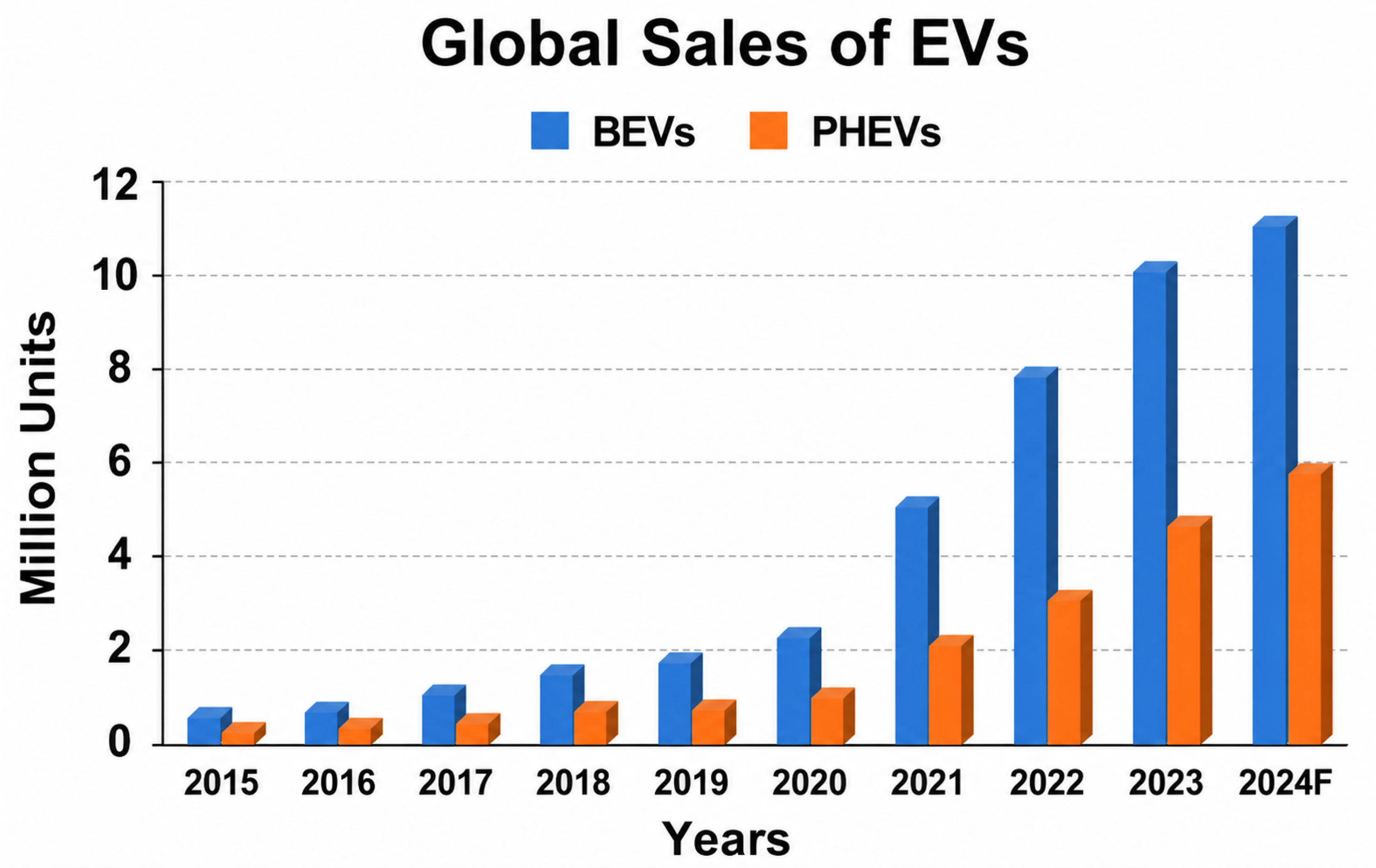
Combined global sales of battery electric vehicles (BEVs) and plug-in hybrid electric vehicles (PHEVs) increased by 22% year-on-year, reaching 1.35 million units [3]. EV sales increased from 0.543 million units in 2015 to 16.5 million units in the first half of 2024, with their market share rising from 0.6% in 2015 to 19.2% in the first half of 2024 [4], as illustrated in Figure 1. Global EV sales further increased by approximately 3.5 million units in 2023 compared with 2022, corresponding to an annual growth rate of 35%. Compared with 2018, this sales volume was more than six times higher. On a weekly basis, new registrations surpassed 250,000 units, exceeding the total annual registrations recorded in 2013. EVs accounted for roughly 18% of total global passenger car sales in 2023, up from 14% in 2022 and just 2% in 2018, reflecting the accelerating market penetration of EVs. BEVs constituted around 70% of the total electric car stock in 2023, underscoring their dominant role in the transition toward low-emission transportation [5]. The recent expectations from the International Energy Agency (IEA) and BloombergNEF (BNEF) indicate that global EV sales will maintain a strong upward trend throughout this decade, reaching between 40 and 50 million units annually by 2030. BEVs are expected to account for roughly 85–90% of these sales [5,6]. The global EV stock is projected to surpass 200 million vehicles by 2030, representing nearly half of the worldwide passenger car fleet under the stated policies scenario [5]. This anticipated growth is largely attributed to ongoing advancements in battery technology, reductions in production costs, and stronger policy measures such as the European Union’s carbon oxide (CO2) emissions standards. In addition, the rapid expansion of charging infrastructure and increased integration of EVs into power grids are expected to further accelerate adoption, positioning EVs to overtake ICE cars in several major markets before the end of the decade.
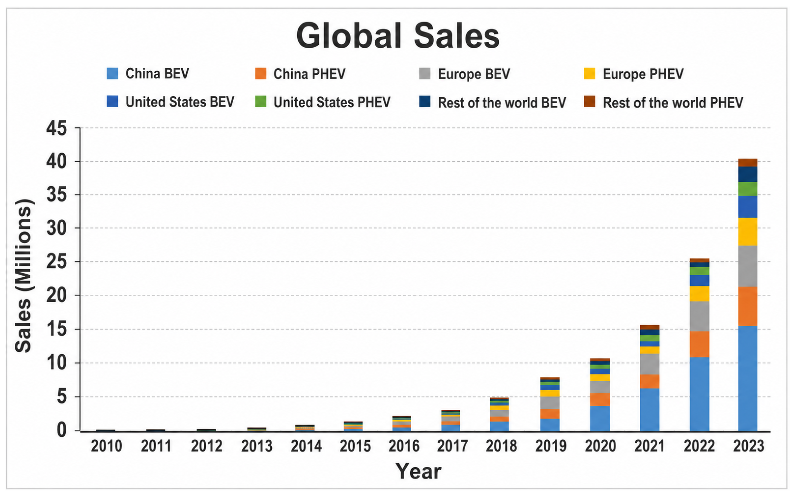
Despite this growth, most EV sales remain concentrated in a few major markets. In 2023, China dominated with nearly 60% of all new electric car registrations, followed by Europe at approximately 25% and the USA at about 10%—together representing nearly 95% of global EV sales, as shown in Figure 2. EVs constitute more than one-third of new car registrations in China, more than one-fifth in Europe, and one-tenth in the USA. Adoption remains low in other developed automotive markets, including Japan and India. This uneven sales distribution creates a similar pattern in global EV stock. The three regions of China, Europe, and the USA together account for two-thirds of worldwide passenger car sales and vehicle population, which will largely determine how their electrification efforts influence global EV adoption patterns [5].
Charging stations are facilities where EVs connect to recharge their batteries. Depending on desired charging speed and location (e.g., home, workplace, or highway), different power levels and connector types are employed. These stations comprise power electronics, safety and control systems, communication modules, and user interfaces to effectively supply electricity to EVs.
The primary contribution of this work lies in the development of a unified, cross-disciplinary framework that bridges the traditional gaps between power electronics hardware, control software, and grid-level infrastructure, providing a comprehensive analysis of the modern EV charging ecosystem within a single reference. Methodologically, this study presents a comprehensive review of EV charging technologies complemented by a structured comparative analysis of 13 review papers published between 2015 and 2026. The selected review papers were identified based on their relevance to key topics addressed in this work, including EV charging technologies, charging standards, power converter topologies, charging control methods, renewable energy integration, and future research challenges. To ensure a consistent evaluation, the reviewed papers were compared according to eight predefined research objectives ( R O 1 R O 8 ) , as summarized in Table 1. This approach enables the identification of research trends, literature gaps, and emerging directions in EV charging technologies. On a hardware level, the paper delivers a rigorous technical evaluation of advanced AC/DC and DC/DC converter topologies, focusing extensively on the integration of next-generation wide-bandgap (WBG) semiconductors like SiC and GaN to map peak efficiencies and power density indicators. Furthermore, it synthesizes software intelligence by contrasting classical battery charging protocols (CC–CV and CP–CV) against advanced linear and non-linear control algorithms, such as Model Predictive Control (MPC) and Sliding Mode Control (SMC). Finally, this review extends into system-level dynamics by providing a strategic roadmap for bidirectional Vehicle-to-Grid (V2G) energy management and multi-port architectures, explicitly addressing how localized energy storage can mitigate grid stability issues caused by intermittent solar and wind energy penetration.
In Table 1, “fully covered” indicates that the corresponding research objective is comprehensively addressed in the reviewed paper; “partially covered” indicates that the topic is discussed but with limited depth, scope, or analysis; and “not covered” indicates that the research objective is not explicitly addressed.
The remainder of this paper is organized as follows: Section 2 provides an overview of different types of EVs, highlighting their respective advantages and disadvantages. Section 3 reviews various battery charging methods and standards applicable to EVs. Section 4 analyzes the power converters used in EV systems, including AC/DC rectifiers and DC/DC converters. Section 5 examines bidirectional power transfer between EVs and the electrical grid. Section 6 focuses on the integration of RESs with the electrical grid and their relationship to EV charging infrastructure. Section 7 discusses the key challenges and emerging trends in EV charging systems powered by RES. Finally, Section 8 presents the conclusions of the study.

2. Types of Electric Vehicles

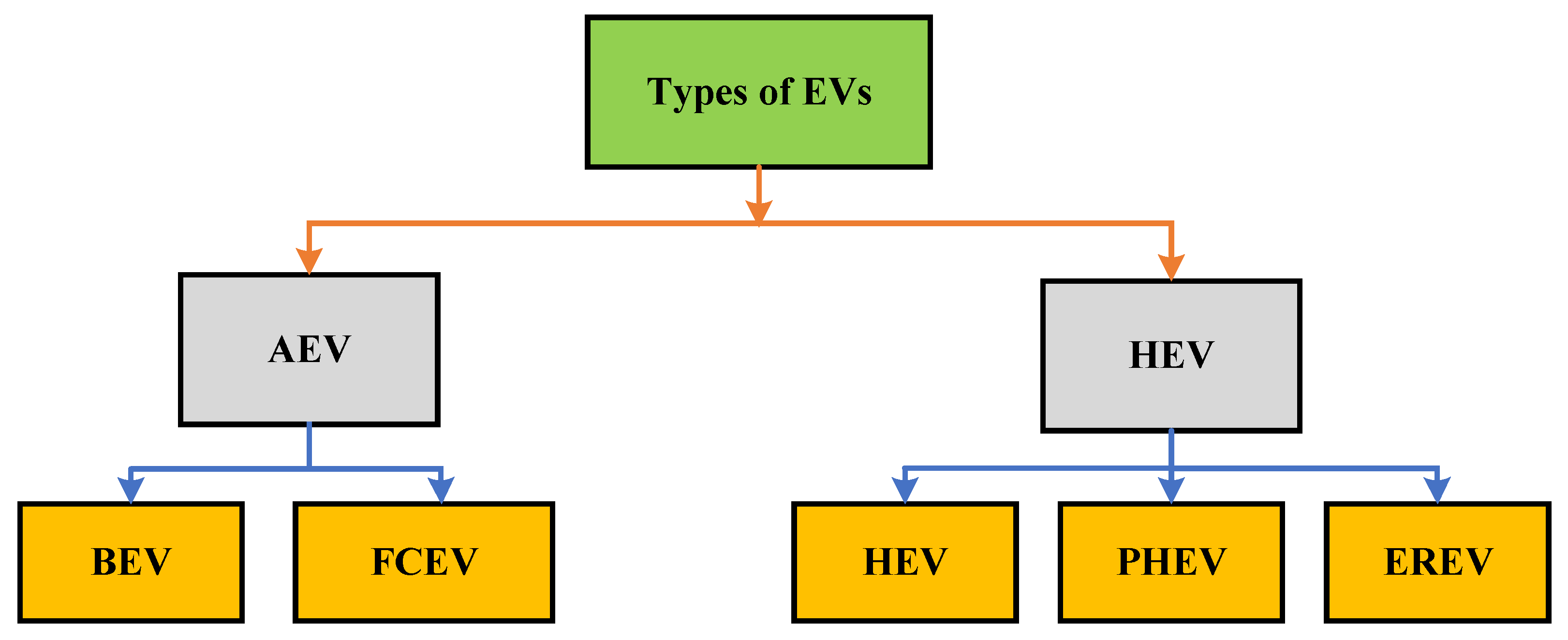
EVs can be broadly classified into two main types. Hybrid electric vehicles (HEVs) rely on two power sources: a conventional fuel (such as gasoline) and an electric motor. All-electric vehicles (AEVs), by contrast, rely solely on an electric motor. HEVs are further categorized into three subtypes: HEVs, PHEVs, and extended-range electric vehicles (EREVs). AEVs are divided into two primary categories: BEVs and fuel cell electric vehicles (FCEVs) [22], as shown in Figure 3.
BEVs are a category of AEVs powered exclusively by electricity stored in a battery, without an ICE. They produce zero tailpipe emissions, making them an effective solution for mitigating global warming and combating climate change. BEVs rely on substantial battery packs as their primary energy source. One key advantage of BEVs is regenerative braking, which recovers kinetic energy during braking and converts it into electrical energy to recharge the battery.
The typical driving range of BEVs varies between 150 and over 500 km. However, some limitations include range anxiety, long charging times, and the need for accessible charging infrastructure [23]. Table 2 presents a comparison of three representative BEV models.
FCEVs are a type of AEV whose energy source is hydrogen fuel cells that power an electric motor. They generate electricity through an electrochemical reaction between hydrogen H 2 and oxygen O 2 , producing only water as a by-product. The advantages of FCEVs include zero tailpipe emissions, quick refueling times (3–5 min), and a long driving range (typically 500–700 km). However, a major drawback is the very limited hydrogen refueling infrastructure. Examples of FCEVs include the Toyota Mirai (2014, Gen 1; 2021, Gen 2), which can travel up to 650 km on a single tank [24], and the Hyundai NEXO (2018), which can travel about 610 km before refueling is required [25].
An HEV is a type of vehicle that combines a conventional ICE with an electric motor powered by a small battery. Unlike a PHEV, an HEV does not need to be charged off-board. Instead, its battery is automatically recharged during driving, primarily through regenerative braking, which captures and stores energy that would otherwise be lost during braking or deceleration. The advantages of HEVs include lower emissions and improved fuel efficiency compared to traditional vehicles. However, HEVs are generally more complex, more expensive, and have a shorter electric-only driving range than conventional cars. An example of an HEV is the Toyota Prius (2026 Prius) [26].
A PHEV is a type of EV that combines a traditional ICE with an electric motor powered by a larger battery equipped with a plug-in charging port. The all-electric driving range depends on the battery capacity and typically varies between 30 and 80 km. The advantages of PHEVs include lower emissions, extended driving range when using the ICE, and reduced fuel consumption. However, they are more expensive than HEVs, require external charging, and have larger batteries compared to HEVs. The Toyota RAV4 Prime (2024–2025) is an example of a vehicle that uses plug-in hybrid technology [27].
An EREV is a type of EV that operates solely using an electric motor for propulsion. It features a large battery that provides substantial electric-only driving range, typically between 60 and 80 km. When the battery is depleted, a small ICE activates—not to drive the wheels directly, but to function as a generator that produces electricity. This electricity either recharges the battery or directly powers the electric motor, thereby extending the total driving range. Unlike a traditional HEV, the ICE in an EREV never directly propels the vehicle, keeping the powertrain fully electric. The BMW i3 is an example of an EREV featuring a lithium-ion battery with an optional gasoline engine used solely as a range extender [27].

3. Standards, Charging Stations, Charging Methods, Charging Controls of EV Batteries

This section provides an overview of the key standards for EV battery charging, including those developed by the Institute of Electrical and Electronics Engineers (IEEE) and the Society of Automotive Engineers (SAE). Both AC and DC charging stations are discussed, along with the various charging methods used in EVs.

3.1. Standards of EV Charging

EV charging standards define how EVs connect and communicate with chargers, specifying plug types, power levels (AC/DC), and communication protocols. These standards vary by region, vehicle type, and charging speed. Different countries adopt specific standards based on local preferences and technological development.
For example, CHAdeMO is widely used in Japan and has been adopted in parts of Europe for fast charging of early Japanese-manufactured EVs, such as the Nissan Leaf [28]. In contrast, the USA primarily follows IEEE [29] and SAE standards, particularly SAE J1772 and the Combined Charging System (CCS) [11]. Meanwhile, China employs the GB/T standards, administered by the Standardization Administration of China (SAC), generally compliant with International Electrotechnical Commission (IEC) frameworks [17,30].
In SAE standards, “Level” refers to the charging power classification, while the equivalent term in IEC standards is “Mode”. Table 3 summarizes the differences among SAE J1772, IEC 62196, IEC 61851-1 [31], and Tesla NACS [32]. According to SAE J1772, on-board chargers operating at AC Level 1 and Level 2 use 120 V and 240 V, delivering approximately 1.92 kW and 19.2 kW, respectively. These moderate power levels are ideal for slow, sustained charging sessions—such as leaving a vehicle plugged in overnight—without imposing heavy loads on the electrical supply. All standards in Table 3 apply to conductive charger types [11]. Off-board chargers operating at DC Mode 3 and Mode 4 typically run at 200–450 V DC and are designed for DC fast charging, currently reaching up to 400 kW.
It should be noted that the standards summarized in Table 3 address different aspects of EV charging. Some standards define charging levels or charging modes (e.g., IEC 61851 and SAE J1772), while others specify connector interfaces and communication requirements (e.g., CCS, CHAdeMO, and GB/T). Therefore, the comparison is intended to highlight their respective roles within the EV charging ecosystem rather than to provide a direct comparison of equivalent standards.
The IEC 62196 standard [33] specifies three AC charging levels and one DC charging level. For DC fast charging, four types of couplers are defined: Configuration AA (CHAdeMO), Configuration BB (GB/T, China), Configuration CC (Type 1 CCS, North America), and Configuration FF (Type 2 CCS, Europe and Australia).
ISO 15118-20 [34] and the SAE J2954 [35] family address complementary aspects of EV charging, covering communication protocols, power delivery methods, and system architectures. ISO 15118-20 focuses on high-level communication for bidirectional charging between the EV and external EV supply equipment (EVSE). In this case, the physical charger is typically a conductive DC fast charger based on the CCS standard. These chargers operate in DC modes or levels, with DC bus voltages up to approximately 1000 V, currents up to 400 A, and maximum powers reaching several hundred kilowatts on current CCS-based systems [34]. In contrast, SAE J2954 standardizes inductive wireless power transfer (WPT). Here, the source charger consists of a ground assembly pad and associated power electronics. Power is supplied as AC on the input side and transferred contactless across the air gap via high-frequency resonant coupling. The standard defines multiple WPT power classes or modes—for example, WPT1 (3.7 kW), WPT2 (7.7 kW), and WPT3 (11 kW) for light-duty vehicles, with extended classes such as WPT9 for heavy-duty applications. The DC voltage and current on the vehicle side are not fixed by the standard but are determined by the onboard rectifier and battery system [35]. Together, these standards illustrate two complementary approaches to EV charging: ISO 15118-20 emphasizes communication and integration for high-power conductive charging, while SAE J2954 provides guidelines for flexible, contactless power transfer, with clearly defined power classes that span light- to heavy-duty applications.
EV charging standards refer to a variety of regional and functional standards that, together, define the overall landscape for the world’s charging infrastructure. There are many standards, some of which include SAE J1772 for AC charging, Levels 1 and 2 (North American legacy, 2010, with revisions in 2024), IEC 62196 for plug types such as Type 1, Type 2, and CCS (global, 2011), IEC 61851-1 for conductive modes (2001), Tesla NACS/J3400 for narrow connectors for AC/DC up to 1 MW (SAE adoption, 2024), ISO 15118-20 for bidirectional V2G communication, and SAE J2954 for wireless charging (3.7 kW to 500 kW, 2017, with heavy-duty modes expected for 2026). All these standards, together, define the overall landscape for the world’s charging infrastructure. In the case of the USA, the primary standards are J1772, NACS, and CCS1, with pilot projects also underway. In the case of Europe, the publicly stated mandates are Type 2, CCS2, and ISO 15118. In the case of China and Japan, the standards are GB/T and CHAdeMO, respectively, with pilot projects for wireless charging underway. Convergence standards are also underway, with the ISO layer building upon the IEC and SAE standards.
CCS, CHAdeMO, ISO 15118, and Open Charge Point Protocol (OCPP) are key technologies that support modern EV charging infrastructure by addressing different aspects of the charging process. The CCS is a widely adopted conductive charging standard that supports both AC charging and high-power DC fast charging through a single connector [11]. CHAdeMO is a DC fast-charging standard developed in Japan and is recognized for its support of bidirectional V2G power transfer [28]. ISO 15118 defines the communication protocol between the EV and the charging station, enabling advanced features such as Plug-and-Charge authentication, smart charging, and V2G operation [34]. In contrast, the OCPP manages communication between charging stations and central management systems, facilitating remote monitoring, billing, load management, and interoperability among charging networks [29].

3.2. Classification of Charging Stations for EVs

EV charging stations are designed to ensure reliable, efficient, and user-friendly energy transfer. Charging stations are generally classified as AC or DC.

3.2.1. AC Charging Stations

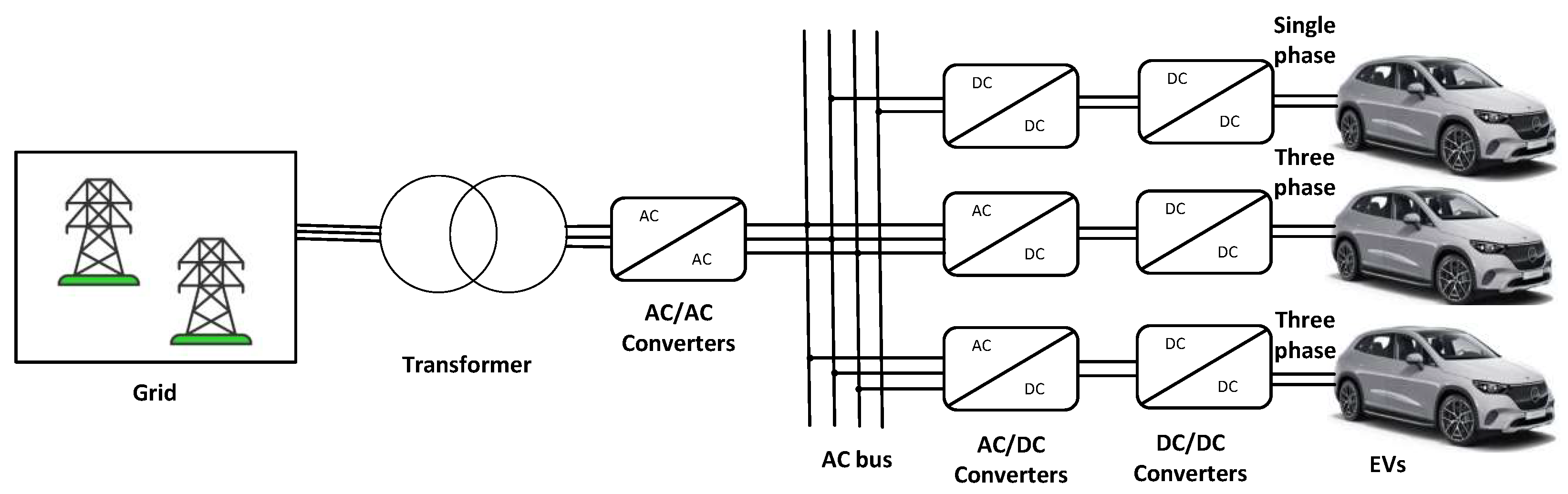
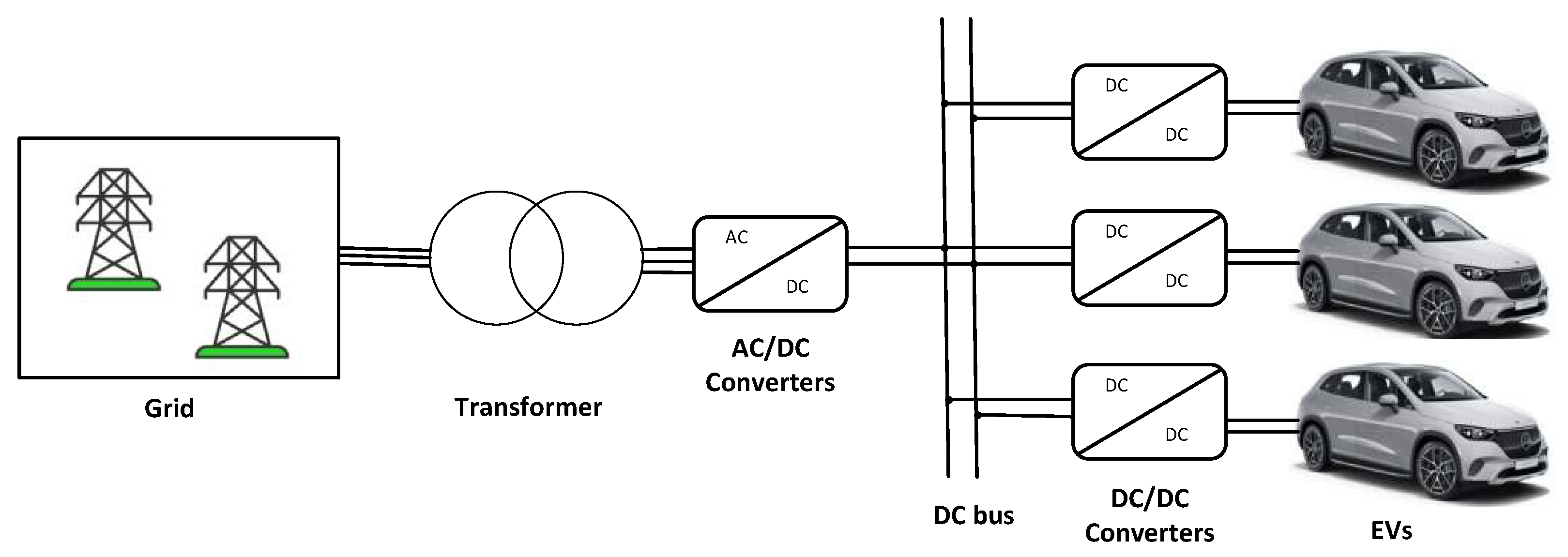
AC charging stations use single-phase or three–phase power, depending on the EV, battery capacity, and desired charging duration. Single-phase systems typically operate at 120–240 V, while three–phase systems operate at 250–480 V, enabling faster charging. Single- and three–phase stations are shown in Figure 4. AC charging stations utilize the vehicle’s on-board charger.
AC stations offer advantages including widespread availability, lower protection requirements, suitability for local loads, and high stability. They also enable control of real and reactive power. However, drawbacks include the need for multiple power converters, which reduce efficiency and rated power output, increase costs, and require additional stages to mitigate harmonics. Maintaining power quality and integrating with RES is more complex due to DC/DC conversion requirements [16]. AC bus-connected slow charging is typically limited to 19.2 kW [14].

3.2.2. DC Charging Stations

DC charging stations deliver current directly to the battery using off-board chargers, making them ideal for fast and ultra-fast charging. They operate up to 1000 V DC, with DC fast charging ranging from 22–200 kW and ultra-fast charging reaching 350 kW today [12] and expected to increase to 500 kW or higher in next-generation chargers. Figure 5 shows a DC charging station.
DC stations offer advantages including simplified control, high efficiency, lower infrastructure costs, and ease of integration with RES and ESS. However, drawbacks include the need for robust protection devices, higher system complexity due to additional power sources, and centralized converters for high-power levels [16].
The planning and siting of high-power off-board DC charging infrastructure require careful geographical and spatial analysis. In [36], feasibility frameworks for highway fast-charging stations were established by mapping spatial demand patterns along transit corridors. However, when deployed at scale, these high-power charging loads can pose significant challenges to local distribution systems. In [37], it was demonstrated that the high power demand of fast chargers can adversely affect voltage stability and reduce the reliability of radial distribution systems.

3.3. Classification of EV Charging Methods

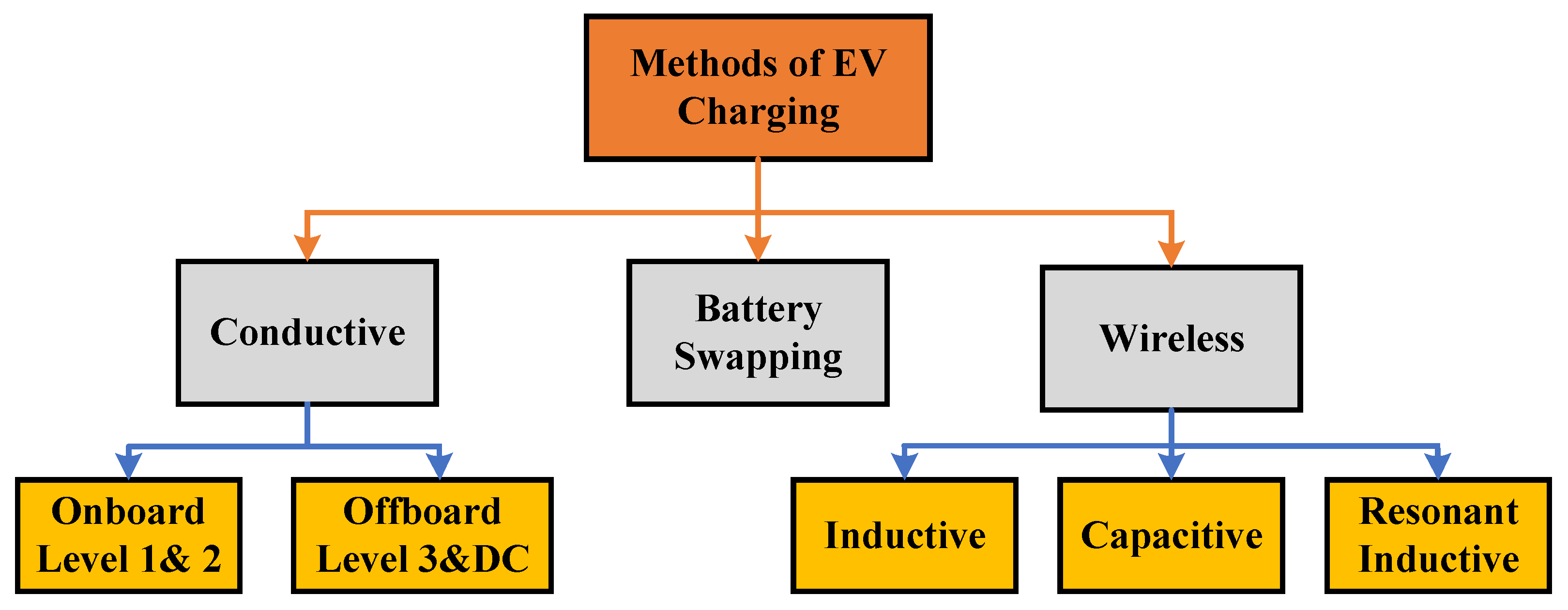
The three main EV charging techniques are conductive charging, wireless charging, and battery swapping. Conductive charging is the most common and efficient method. It can be implemented as on-board charging (charger inside the vehicle) or off-board charging (external charger). Figure 6 shows these methods.

3.3.1. Conductive Charging

Conductive charging delivers electricity directly via plugs and cables, supporting Level 1, 2, 3, and DC fast charging. Its benefits include high efficiency, low energy loss, widespread availability, and integrated protection against overvoltage and overcurrent. It also supports bidirectional power flow, including V2G and Grid-to-Vehicle (G2V) [38].
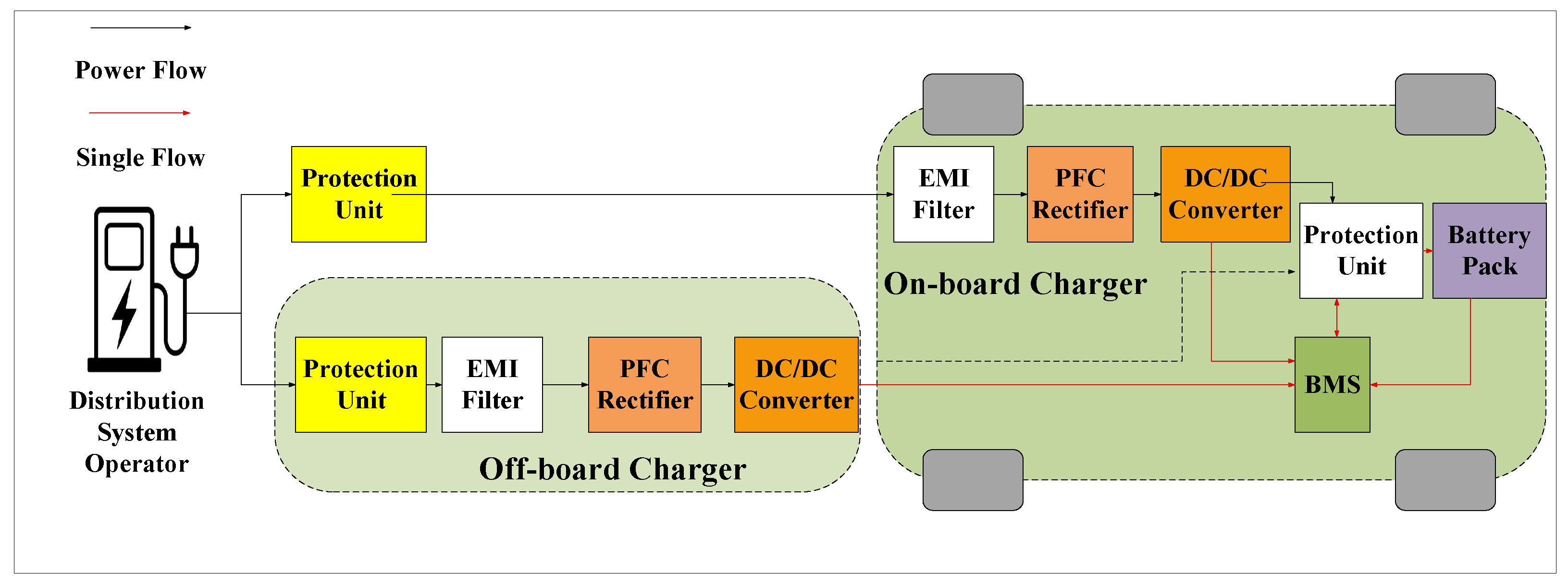
On-board chargers convert AC from the grid to DC for the battery, supporting Level 1 and 2 charging with low power and long durations (hours to a full day). They require less infrastructure and are suitable for residential or workplace charging [39].
Off-board chargers provide DC directly, supporting Level 3 and fast charging. Charging times are reduced to minutes, but they require significant infrastructure, typically located along highways and at public hubs. Figure 7 illustrates these configurations. The battery management system (BMS) manages battery charging in both cases.

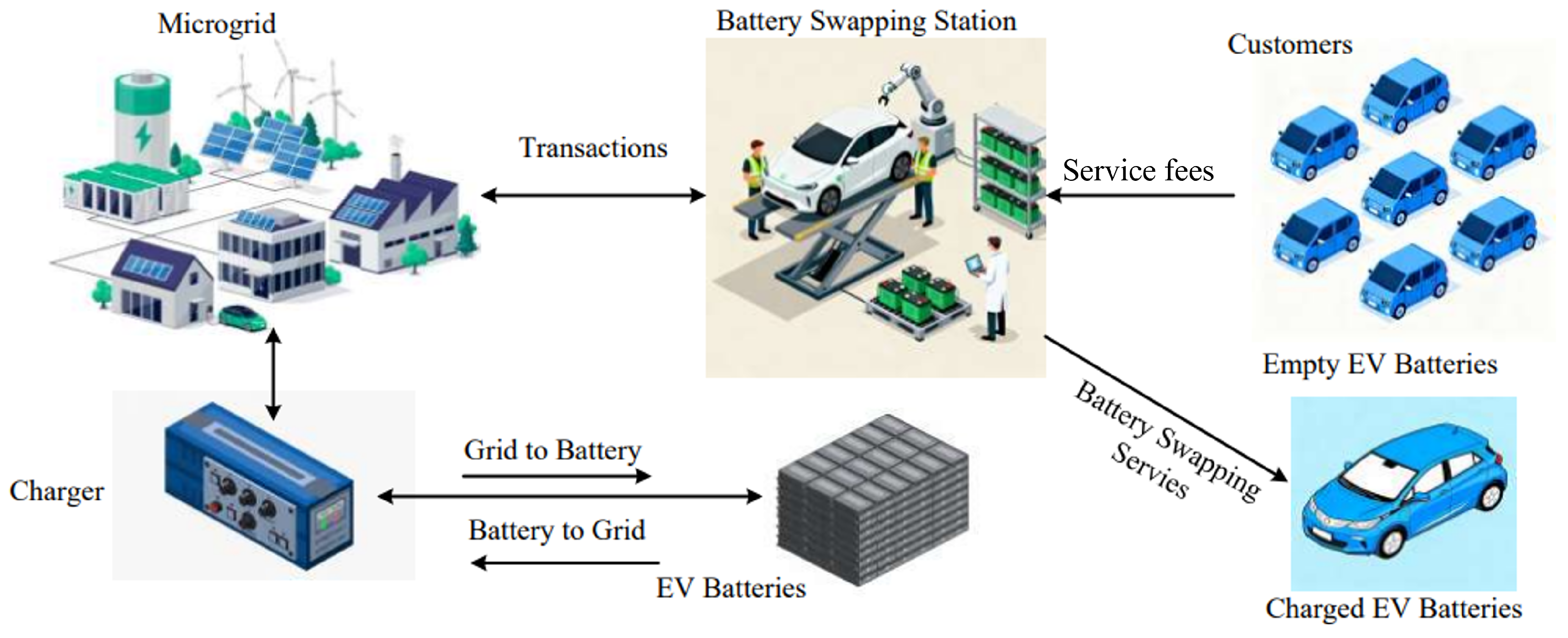
3.3.2. Battery Swap Stations

Battery swapping replaces a depleted battery with a fully charged one, reducing downtime and improving convenience [40]. Robotic systems complete swaps in minutes, similar to refueling conventional cars [41]. For example, Tesla swaps a battery in 1.5 min, reducing range anxiety [42,43]. The swapping company manages maintenance, quality, and warranty. Off-peak charging reduces grid stress [44,45]. Figure 8 shows a battery swapping station.

3.3.3. Wireless Charging

WPT delivers electricity without physical connectors via electromagnetic fields (EMFs). Methods include Capacitive Power Transfer (CPT), Inductive Power Transfer (IPT), and Resonant Inductive Power Transfer (RIPT) [46]. Only CPT and IPT are used for EV batteries, with IPT being the most effective due to power range and air gap (10–40 cm) [47]. IPT allows charging while driving, is maintenance-free, and requires no physical connection.
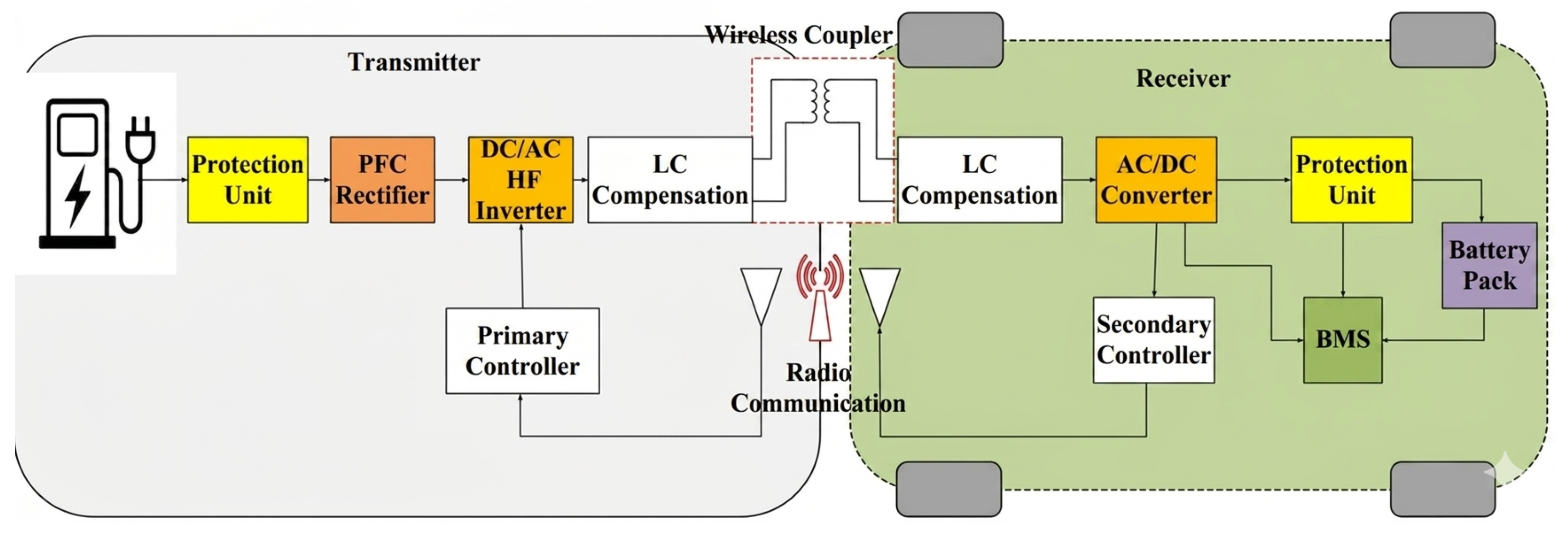
Figure 9 shows an IPT system, consisting of a transmitter circuit (grid-connected AC/DC rectifier, PFC, high-frequency inverter, LC network, protection unit) and a receiver circuit in the vehicle (LC network, AC/DC rectifier). The transmitter coil generates a high-frequency magnetic field, inducing voltage in the receiver coil, which is rectified to DC to charge the battery [48].
The IPT charging modes are classified into:
  • Static: Vehicle stationary; simple infrastructure, limited locations.
  • Dynamic: Charging while moving; reduces battery size, requires high infrastructure investment.
  • Quasi-dynamic: Temporary stops (traffic lights); faster than static, lower infrastructure cost.
The drawbacks of IPT charging include limited power transfer, eddy current losses, communication latency, high cost, and potential EMF-related health risks [49].
Recent developments in EV charging methods focus on ultra-fast charging rates above 400 kW, artificial intelligence-based predictive charging to improve grid stability, and V2G integration to facilitate power supply to the grid during peak demand [50]. Recent developments in EV charging and battery technology indicate that laboratory-scale and early prototype solid-state lithium batteries for EV applications can achieve up to 80% SoC within 15–30 min under optimized fast-charging conditions, in addition to advancements in liquid-cooled battery systems and DC-coupled storage solutions aimed at reducing grid stress [51]. Sophisticated charging methods, including constant current/constant voltage charging with soft-switching, are being employed to reduce battery aging during high C-rate charging sessions [52,53]. Other methods, like constant power/constant voltage charging, are also under investigation [54]. In [55], a comprehensive comparative analysis is presented for four observer-based control techniques—Luenberger, Sliding Mode, PI, and PID—used to estimate states of a lithium-ion battery. The study considers a second-order equivalent circuit model and evaluates performance using driving profiles and real-world EV field data. Meanwhile, Ref. [56] proposes an intelligent fast-charging strategy for lithium-ion batteries, that optimizes charging duration while ensuring thermal safety and satisfying physical constraints.

3.4. Charging Control Protocols

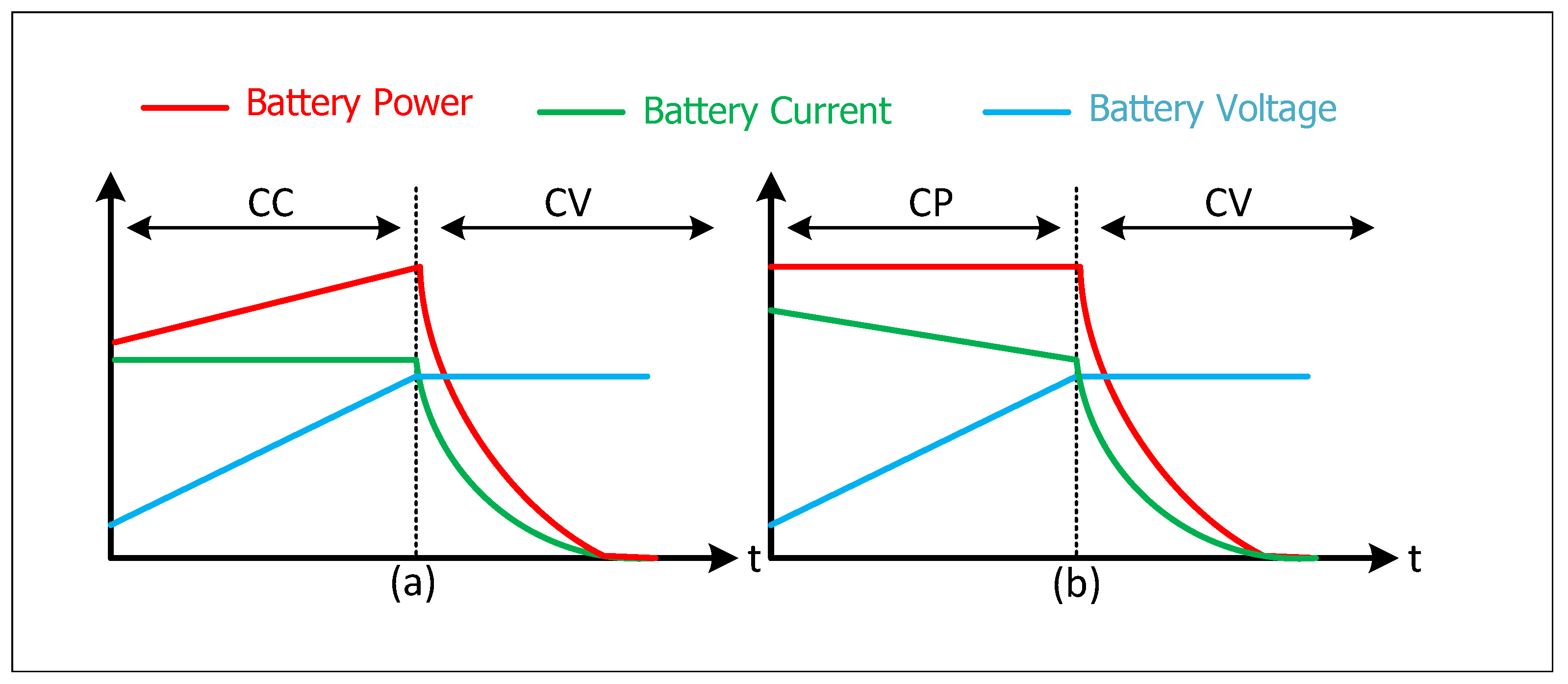
EV battery charging requires efficient and reliable control strategies to ensure fast, safe, and durable energy transfer. Among the various approaches, the constant current–constant voltage (CC-–CV) strategy is widely used in EV battery charging because of its simplicity and reliability. In this conventional charging protocol, the battery is charged at a constant current until its terminal voltage reaches a specified limit, after which the charging current gradually decreases under constant voltage regulation. To improve charging performance, several advanced charging methods, including multi-stage CC, pulse charging, boost charging, and variable current profiles, have been proposed [54]. Moreover, the advanced method of charging the EV battery is constant power–constant voltage (CP–CV) control.
In the CP-–CV charging strategy, the initial charging stage operates under constant power before transitioning to constant voltage. Compared with CC-–CV, the CP-–CV protocol maintains higher charging power during the initial stage, which can reduce charging time. It also operates with lower charging current, which could contribute to limiting battery temperature and prevent overheating while supporting higher C–rates during fast charging [54]. The CC–CV and CP–CV EV charging protocols are illustrated in Figure 10. The controller regulates the charging current and voltage to keep them within safe limits, thereby preventing both overcharging and undercharging. In addition, it manages the battery thermal system and monitors the state of charge (SoC) to reduce the risk of thermal runaway and improve battery lifespan. The following section presents various linear and nonlinear control techniques used in battery charging protocols together with their operating principles.

3.4.1. Proportional–Integral (PI) Controller

A linear PI controller is widely used in EV battery charging because it is simple, reliable, and effective. The proportional term makes the system respond quickly to changes in the charger parameters, while the integral term removes steady-state error and improves charging accuracy. In practice, this makes it well suited for regulating charging current and voltage during the CC and CV phases, even when battery conditions or supply variations change. Several studies have used PI-based control in EV battery charging systems to improve regulation and dynamic performance [57]. In addition, modified plug-in EV charger controllers with grid-support functionality and revised PI strategies for DC/DC conversion have been reported to improve charging performance, reduce overshoot, and increase efficiency [58]. More recently, optimized PI-based control has also been applied in PV-integrated EV charging microgrids to support better voltage regulation and adaptive energy management [59].

3.4.2. Model Predictive Controller (MPC)

Charging an EV battery using model predictive control (MPC) begins by modeling the battery and charger dynamics in discrete time with periodic sampling and setting physical limits on current, voltage, SoC, and temperature, as well as grid or charging-station power constraints. At the beginning of each sampling period, MPC uses the measured battery current, SoC, voltage, and temperature, together with forecasts of the expected charging time, to solve an optimization problem over a future prediction horizon. This optimization computes a sequence of charging power or current references that minimizes charging time or battery degradation while ensuring efficient use. The controller then applies only the first value of this sequence to the charger and at the next expected value, repeats the whole process with updated measurements and forecasts in a receding-horizon manner, continuing until the battery reaches the desired SoC, at which point the charging session is safely stopped [21]. Several studies have used MPC in EV charging because it can manage charging limits while still improving performance. For instance, it has been applied to fast charging of EV batteries to reduce charging time and temperature rise, to plug-and-play EV charging dispatch so that voltage limits are respected, and to stochastic energy management in charging hubs that include renewable generation and storage. In [60], a hybrid fuzzy-MPC control strategy that simultaneously optimizes fast EV charging, advanced battery thermal management, and renewable grid integration has been proposed.

3.4.3. Fuzzy Logic Controller

A fuzzy logic controller (FLC) is an approach widely used in nonlinear systems. It can be applied without requiring a precise mathematical model and adeptly manages uncertainties. Its core principle relies on expert knowledge and linguistic rules rather than intricate equations, enabling intuitive design. Moreover, it can be integrated seamlessly with PI, PID, or hysteresis controllers to leverage their strengths, yielding smooth responses and straightforward tuning. Studies optimizing EV charging via SoC, error, and grid conditions demonstrated that FLC can be used to effectively handle the battery’s changing process by smoothly adjusting charging current and voltage, thereby improving efficiency, ensuring safety, and reducing battery stress [61]. An FLC-based PID strategy for PV-powered chargers was used to improve voltage regulation and to minimize power losses in [62], while a Mamdani fuzzy approach was employed in [63] to enhance smart V2G charging/discharging, SoC management, and cost reduction.

3.4.4. Sliding-Mode Controller

Sliding Mode Control (SMC) uses a discontinuous control law to drive a selected system variable, known as the sliding variable, toward a predefined sliding surface in finite time. Once the trajectory reaches this surface, the controller maintains the system motion along it until the desired operating condition is achieved. SMC is widely used in power electronics because of its robustness against parameter variations and external disturbances. Originally it was developed in the analog domain, and later digital SMC was also used. Both analog and digital approaches are well suited and widely applied to power electronic converters [21,64,65]. In EV battery charging, SMC works very well because it quickly adapts to changes [66].
SMC has been extensively utilized in EV battery-charging systems, proving its robustness in different topologies and operational scenarios. In [66], SMC was introduced for fast-charging of EVs, where it was shown that it effectively eliminates voltage overshoots and current peaks during CC–CV phases compared to fuzzy-logic control. In [67], a PWM control law based on SMC was used for isolated DC/DC converters in battery storage, showing superior transient response and better steady-state accuracy under parameter uncertainties compared with a PI regulator. In [68], SMC was combined with a Linear Quadratic Regulator (LQR) for PV-powered EV hybrid storage, yielding faster dynamics and improved disturbance rejection under variable irradiance conditions.

4. Types of Power Converters for EVs

Power electronic converters are essential components in EV charging systems, as they connect EVs to the power grid. Advanced converters improve system efficiency, enable faster battery charging, and maximize power transfer [69]. They also facilitate more effective integration of EVs with RES through enhanced converter and controller technologies.
Two primary types of power converters are used in EV charging: AC/DC converters and DC/DC converters. These converters often operate simultaneously to efficiently charge the EV battery. AC/DC converters, whether single-phase or three–phase, not only convert AC power to DC but also improve power quality and implement power factor correction (PFC). DC/DC converters regulate DC power before delivering it to the battery [18].

4.1. AC/DC Converters

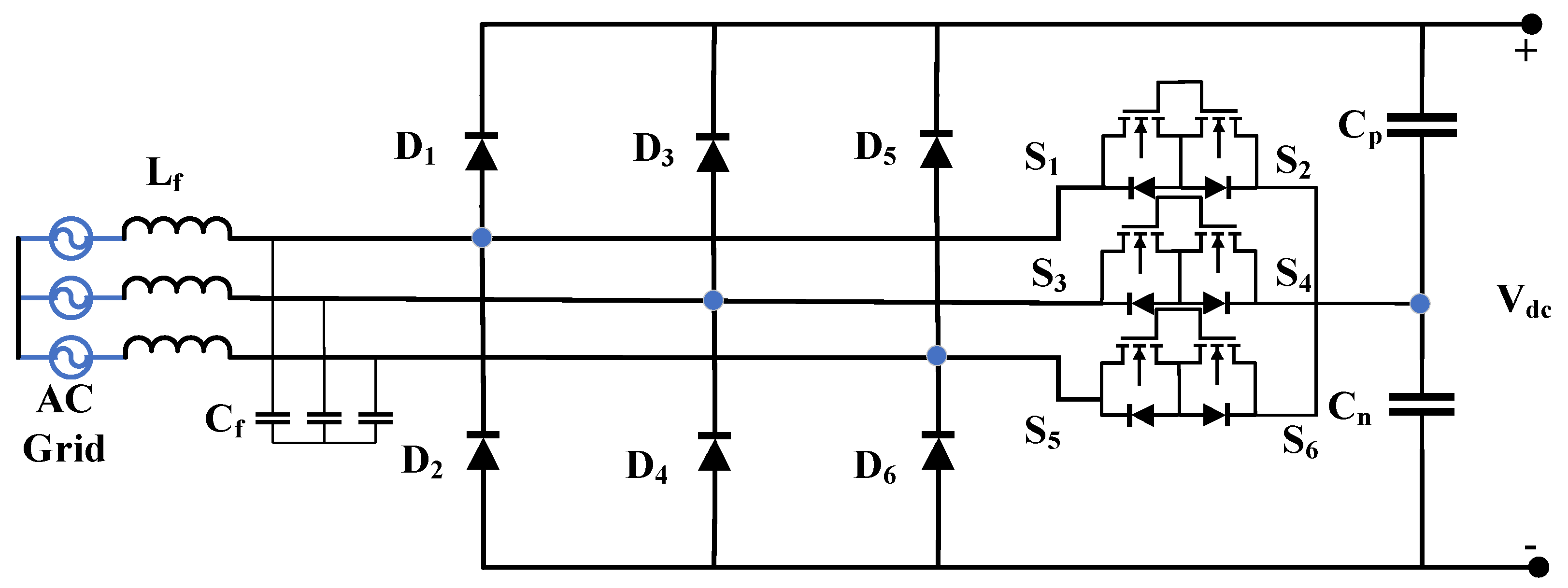
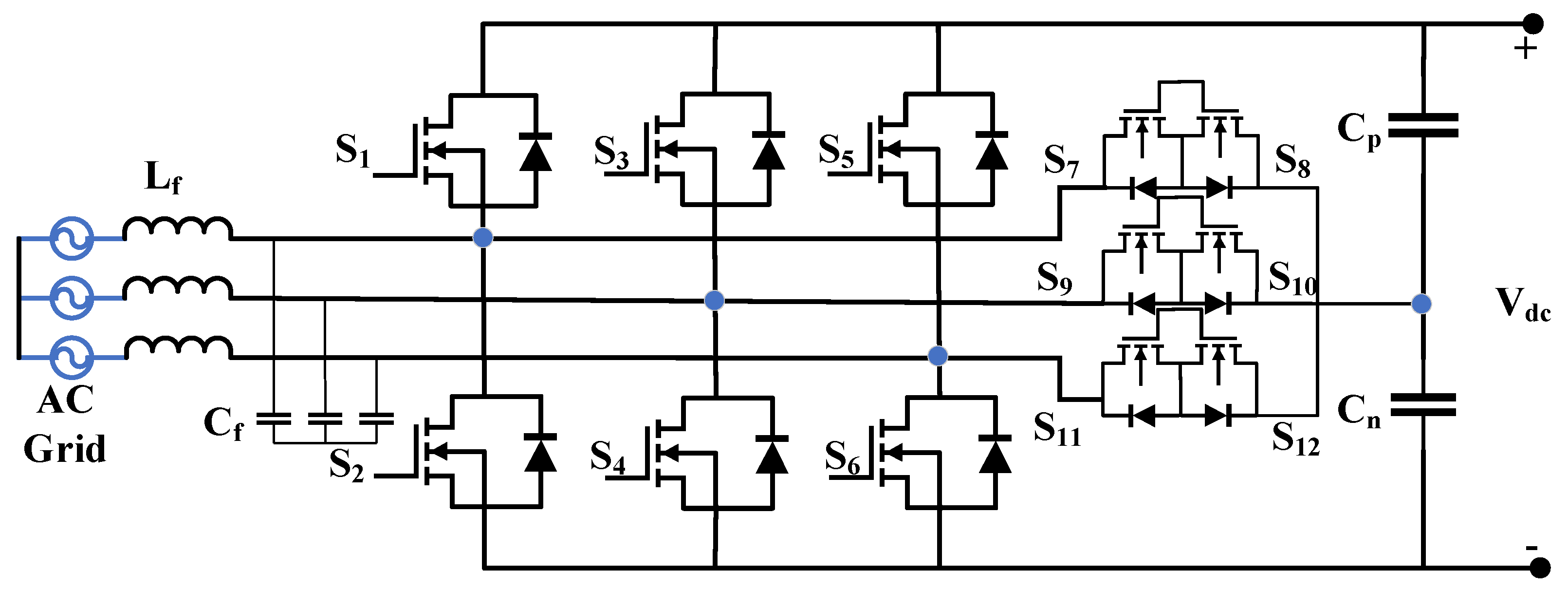
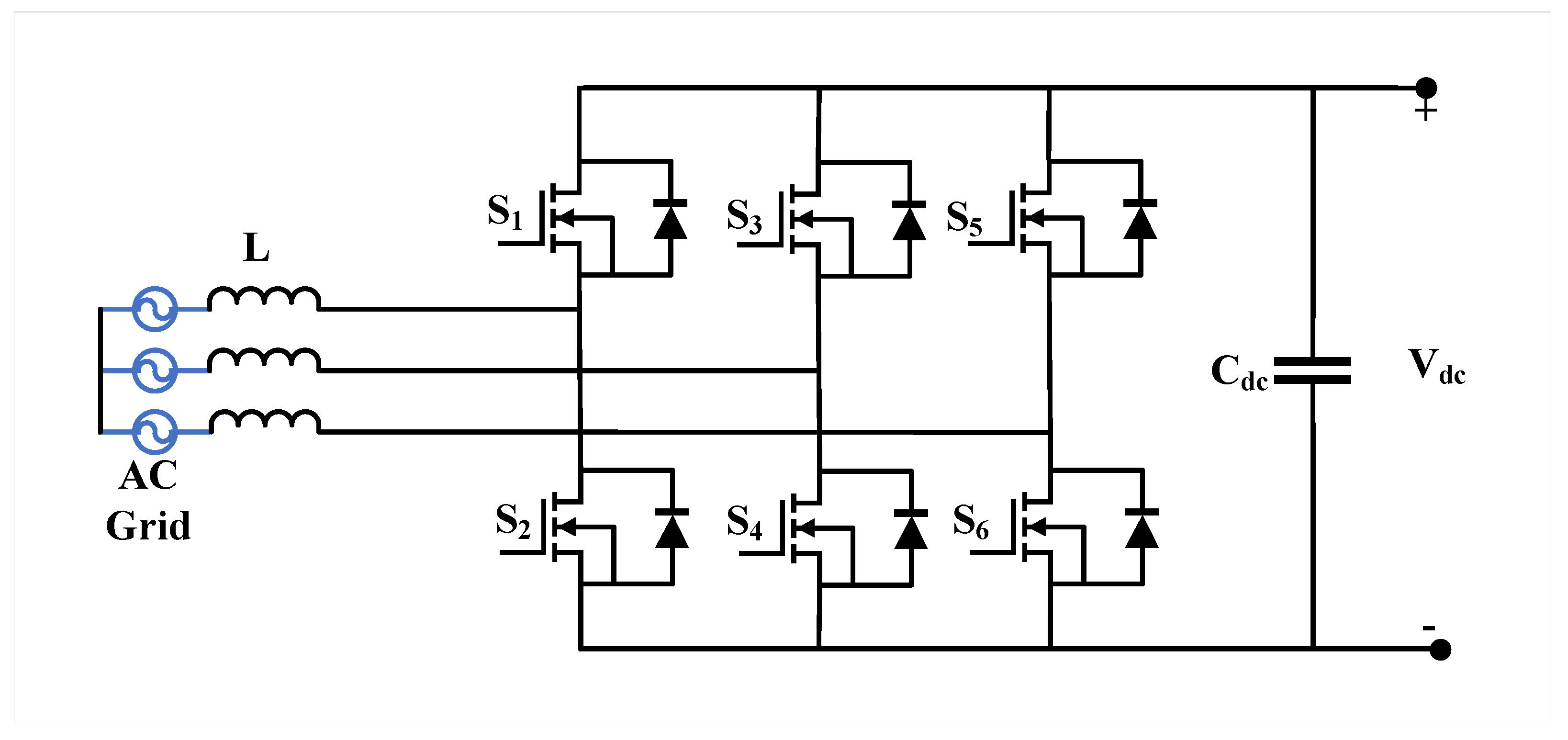
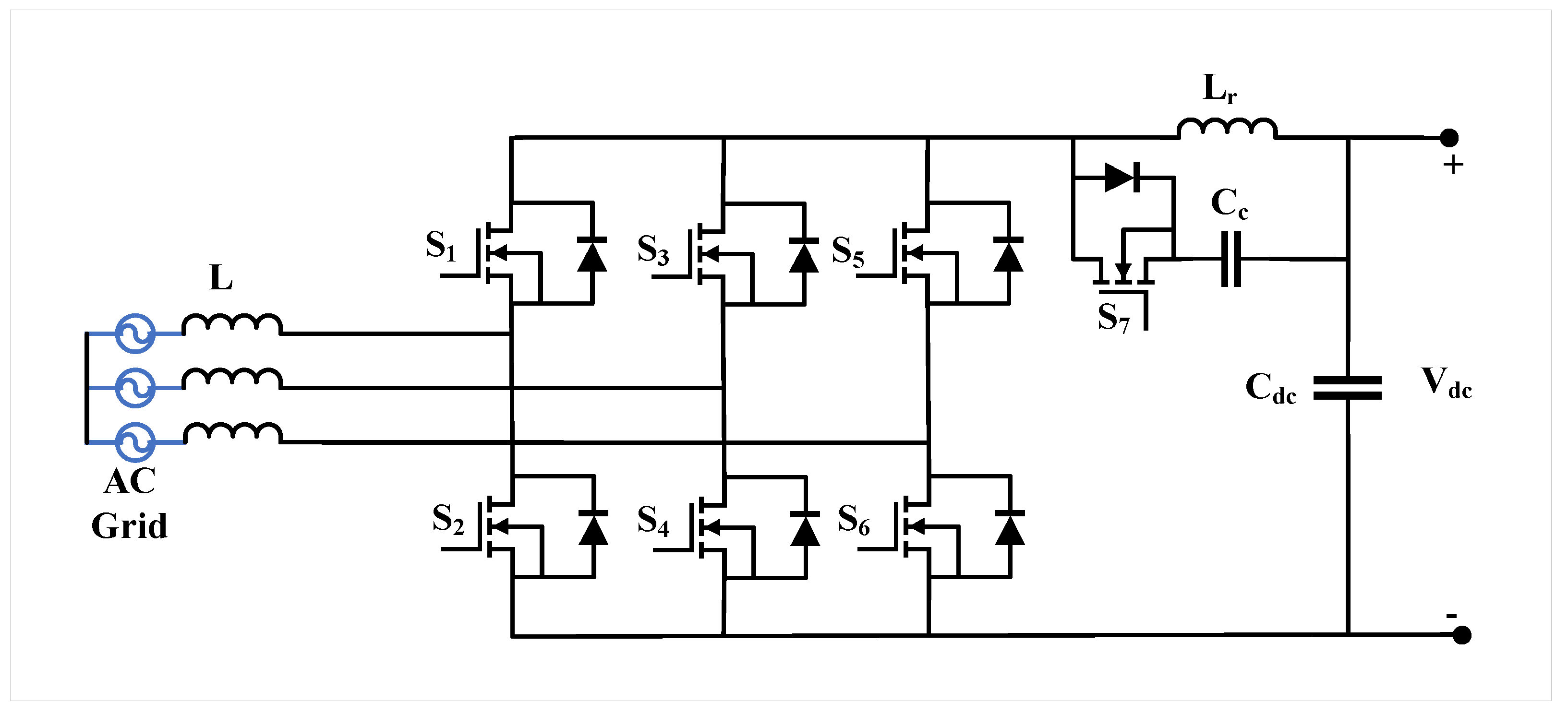
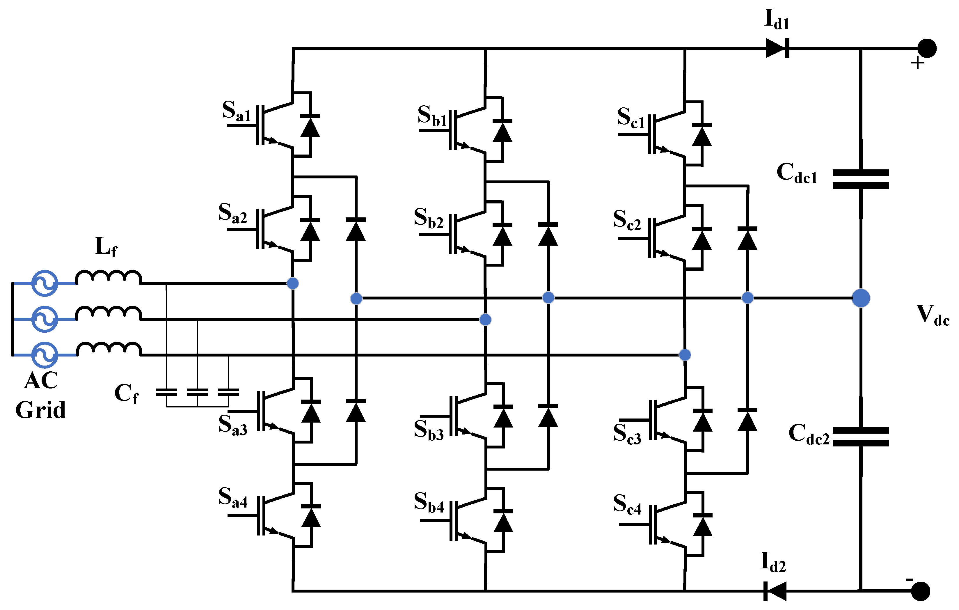
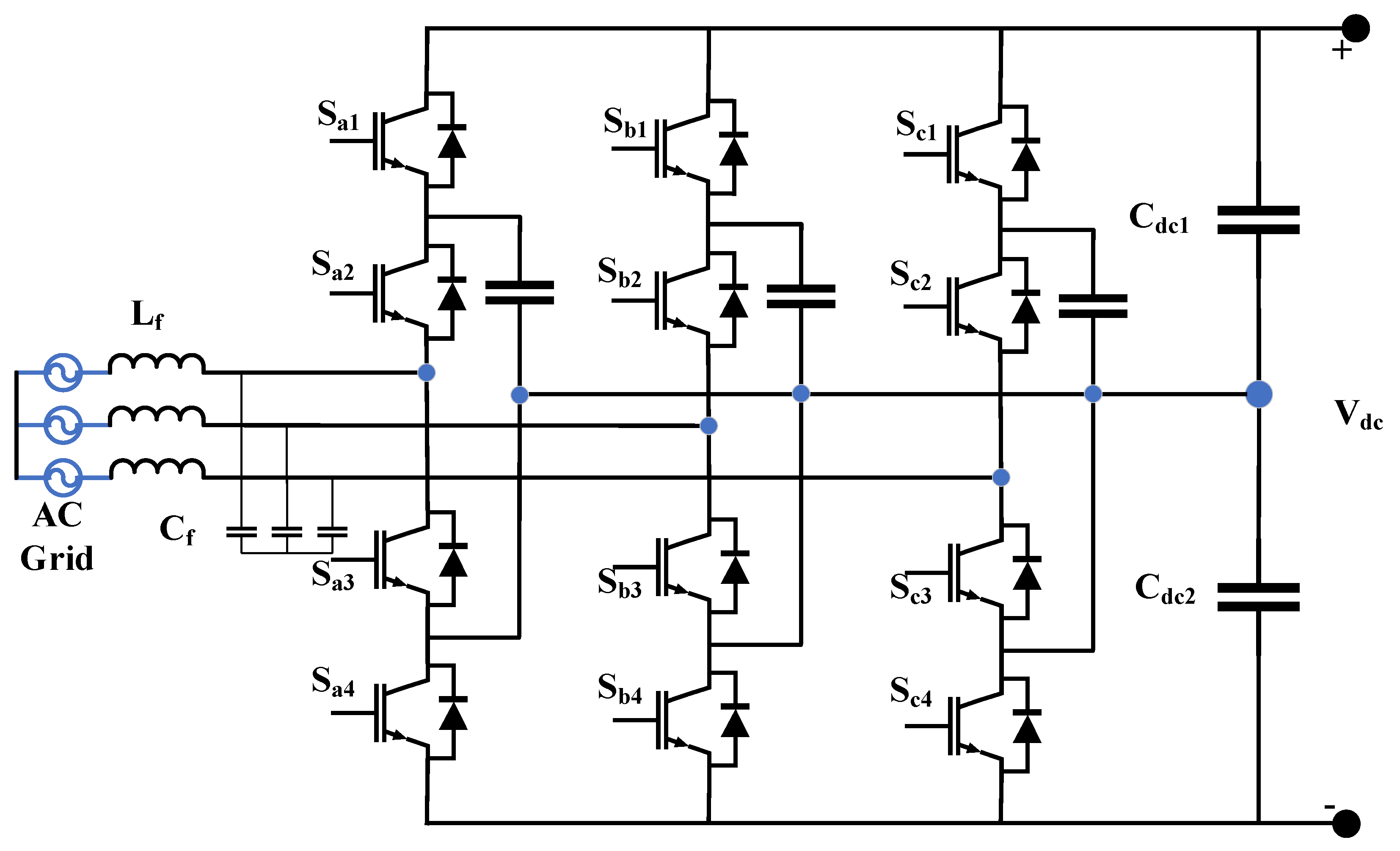
The AC/DC converter serves as the first stage of an EV charger and interfaces directly with the grid. It converts AC to DC and typically uses an input LC filter to reduce current ripple. Several AC/DC converter topologies are widely employed, including the three–phase buck–type rectifier, three–phase boost rectifier, Swiss rectifier, Vienna rectifier (unidirectional and bidirectional), ZVS-enabled three–phase rectifier, three–level neutral-point-clamped (NPC) converter, three–phase flying capacitor converter, cascaded H–Bridge converter, and modular multilevel converter (MMC) [70].

4.1.1. Buck–Type Rectifier

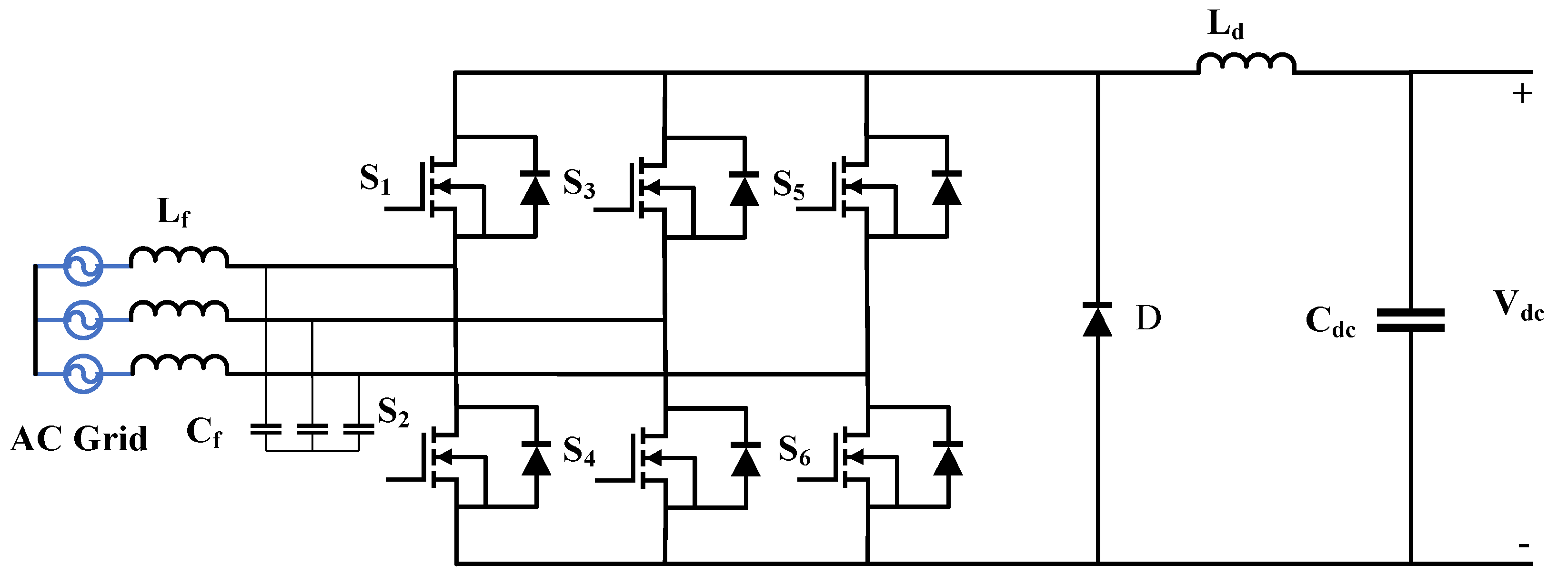
The three–phase buck rectifier outputs a voltage lower than its input voltage. Compared to boost rectifiers, it offers wider output voltage regulation, simpler control, robust current protection, low total harmonic distortion (THD), high efficiency, and effective PFC [71,72]. Figure 11 illustrates a conventional Six–switch three–phase buck rectifier. Each phase connects two switches in series with a freewheeling diode.
The traditional buck converter is suited for low-power charging, providing enhanced efficiency and power quality [73]. Improvements include replacing the freewheeling diode with two series-connected diodes to reduce transistor stress and switching losses [74], and adding input filters to decrease current ripple. Eight-switch variants further reduce switch losses [75].

4.1.2. Swiss Rectifier

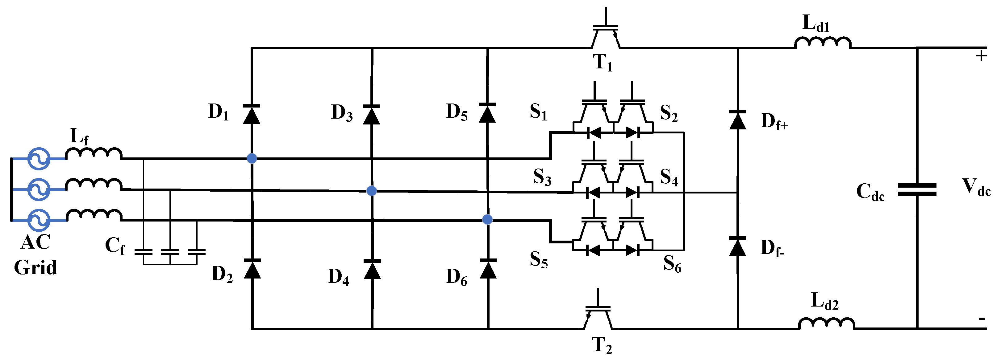
The Swiss rectifier, shown in Figure 12, is a buck–type PFC converter for 250–450 V DC battery systems and 380 V AC input [76]. It consists of a three–phase input, LC filter, and two freewheeling diodes that reduce voltage stress and conduction losses. Implemented as a three–phase stage combined with two DC/DC buck converters, it requires fewer high-frequency switches than Single–stage isolated topologies, yielding higher efficiency and simpler design [77,78].
Single–stage full–bridge Swiss rectifiers can achieve over 95% efficiency at half-rated power while maintaining low THD. Interleaving further improves reliability and bandwidth and reduces input/output ripple [79]. Multilevel Swiss rectifiers enable high-power applications, and bidirectional Swiss rectifiers support V2G operation [80].

4.1.3. Three–Phase Vienna Rectifier

The Vienna rectifier is a three–phase boost–type PFC converter extensively used in high-power EV applications. Its advantages include regulated DC output, high efficiency, reduced THD, fewer switches, lower semiconductor stress, unity power factor, and no neutral connection requirement [81,82]. Figure 13 and Figure 14 show unidirectional and bidirectional Vienna rectifiers, respectively.
Unidirectional Vienna rectifiers use three input inductors, phase-specific power bridges, and split DC–link capacitors. Bidirectional configurations replace diodes with active switches to support V2G, increase efficiency, and reduce conduction losses [83]. Virtual synchronous machine (VSM) control enables large-scale EV integration while maintaining grid stability [84].

4.1.4. Three–Phase Boost Converters

Three–phase boost converters provide bidirectional operation, high efficiency, low THD, and high output voltage. Figure 15 and Figure 16 show the conventional and ZVS-enabled three–phase boost rectifiers. ZVS reduces switching losses and EMI, enabling high-frequency operation and near-unity power factor, making it suitable for fast charging and RES integration [85,86,87].

4.1.5. Multilevel AC/DC Converters

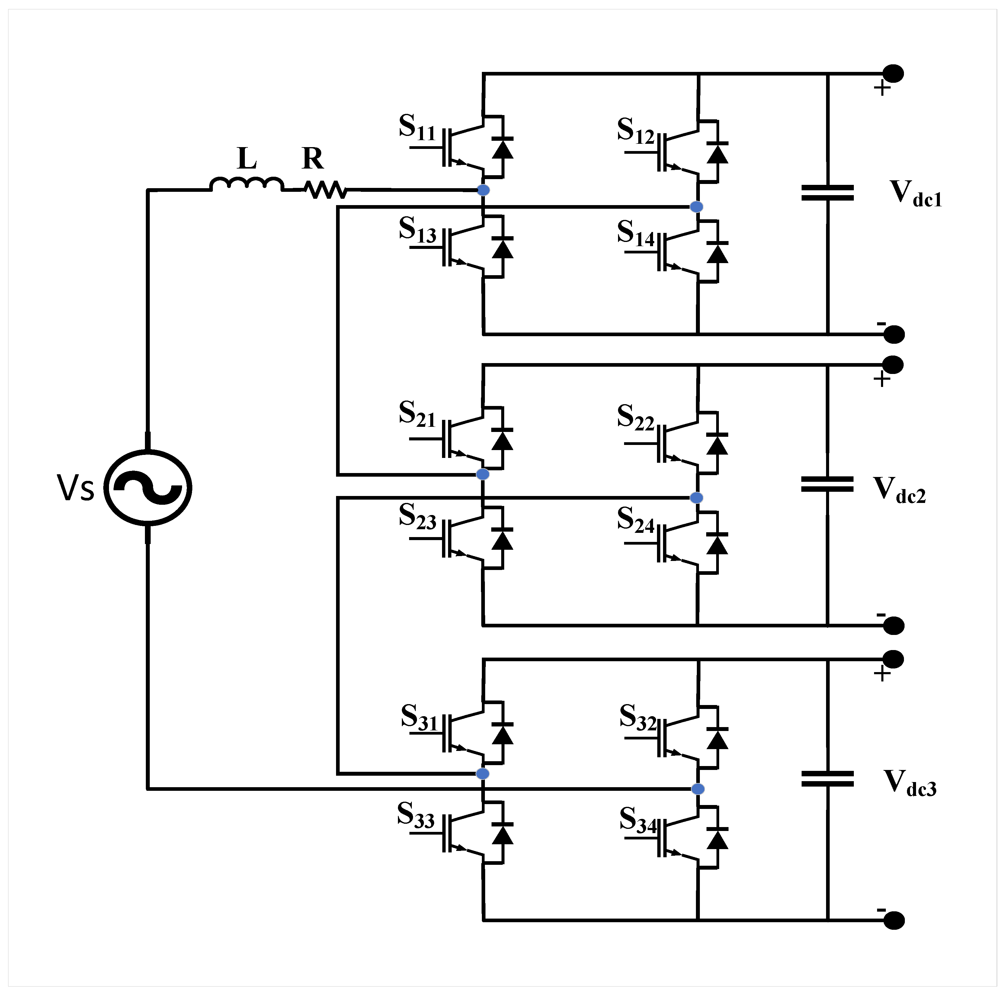
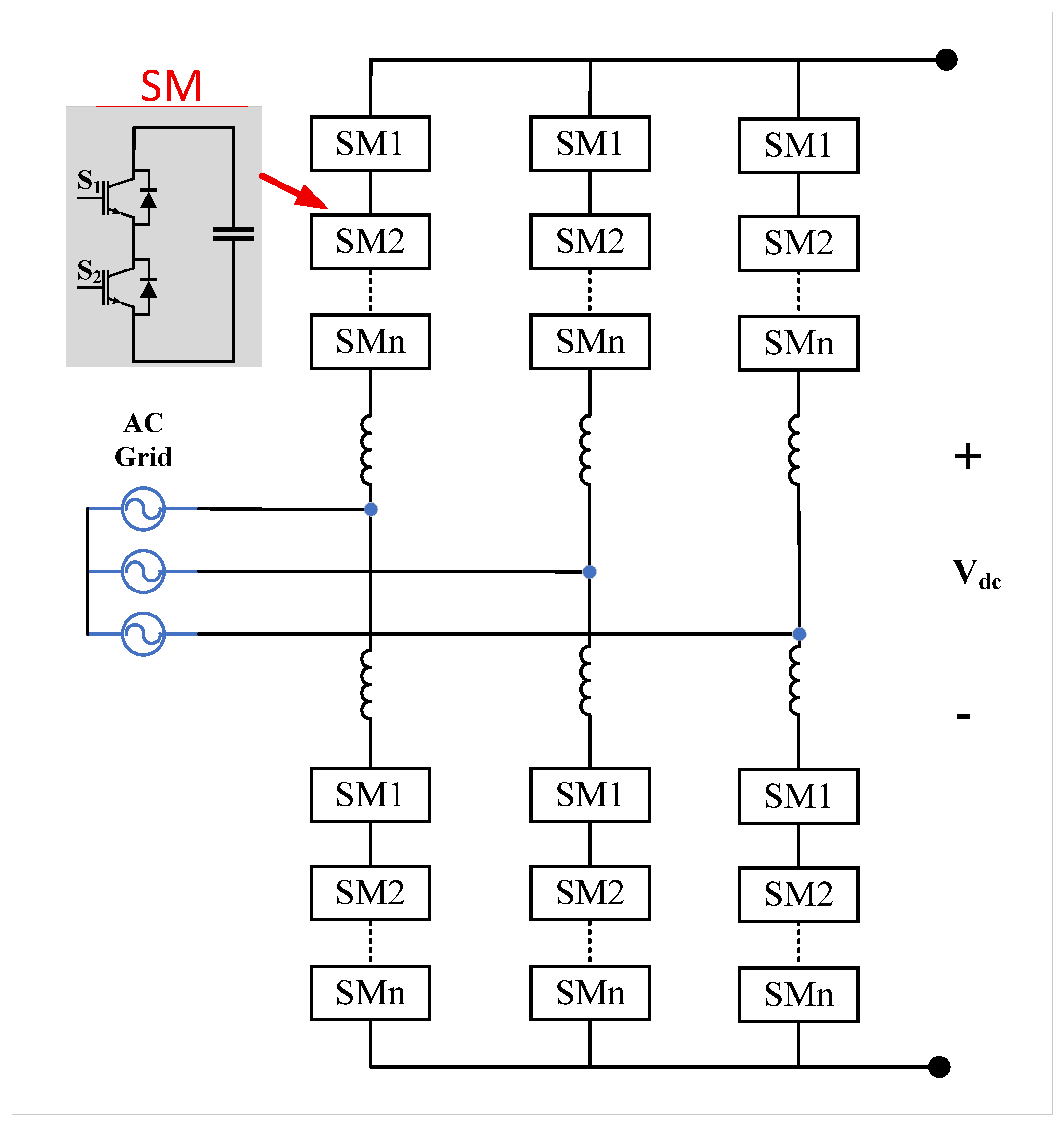
Multilevel converters are used for fast and ultra-fast charging due to their high efficiency, high power density, and ability to generate high-quality voltage waveforms [88]. The topologies of multilevel converters include:
  • Neutral-Point-Clamped (NPC) converters (Figure 17)
  • Flying Capacitor (FC) converters (Figure 18)
  • Cascaded H–Bridge (CHB) converters (Figure 19)
  • Modular Multilevel Converters (MMCs) (Figure 20)
NPC converters reduce harmonics and switching losses [89,90]. FC converters offer the possibility of using small and low-cost components if voltage balancing among the cells is guaranteed [91,92]. CHB and MMC topologies are scalable and suitable for high-power applications, with MMC offering improved stability, lower harmonics, and modularity [88,93,94]. For EV applications, WBG semiconductor devices like silicon carbide (SiC) and gallium nitride (GaN) are very appealing because they provide significant advantages over traditional silicon-based technology. Compact, lightweight, and thermally stable EV charger designs are made possible by their high efficiency, fast switching, and capacity to operate at higher voltages and temperatures. WBG devices have been used by EV manufacturers in recent years to improve overall vehicle performance and charging efficiency. These characteristics directly address major design limitations in contemporary EV power electronics by increasing power density, lowering conduction and switching losses, raising switching frequencies, and reducing passive components [21]. Table 4 presents a comparison of three–phase AC/DC converter topologies for EV charging, highlighting implementations with WBG devices. The efficiency data for the different converter topologies were compiled from various reported sources. Specifically, the efficiency of the MMC was obtained from experimental prototype benchmarks [88,93,94], the DAB converter from commercial product platforms and reported implementations [95], the LLC resonant converter from literature-based design validations [96,97,98,99], and the interleaved buck converter from laboratory experimental studies [100,101,102,103,104].

4.2. DC/DC Converters

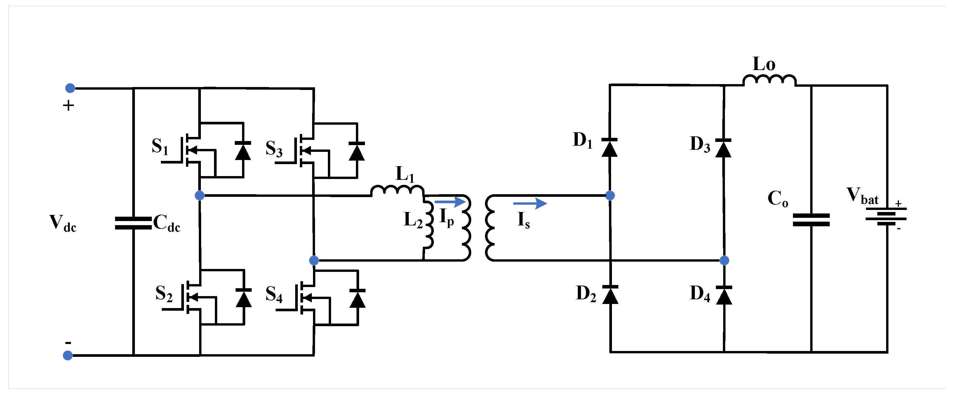
DC/DC converters connect directly to the EV battery and convert the DC voltage to the required battery charging voltage. They can be isolated or non-isolated and unidirectional or bidirectional. Isolation is typically required in high-power applications, using either line-frequency or high-frequency transformers [105,106]. Non-isolated converters include buck, boost, buck-boost, SEPIC, Zeta, and Ćuk topologies, often enhanced via interleaving or multilevel designs. Isolated converters include full–bridge, half-bridge, forward, flyback, Z-source, and multiport configurations, with soft-switching methods such as ZVS and ZCS [107,108].

4.2.1. Isolated DC/DC Converters

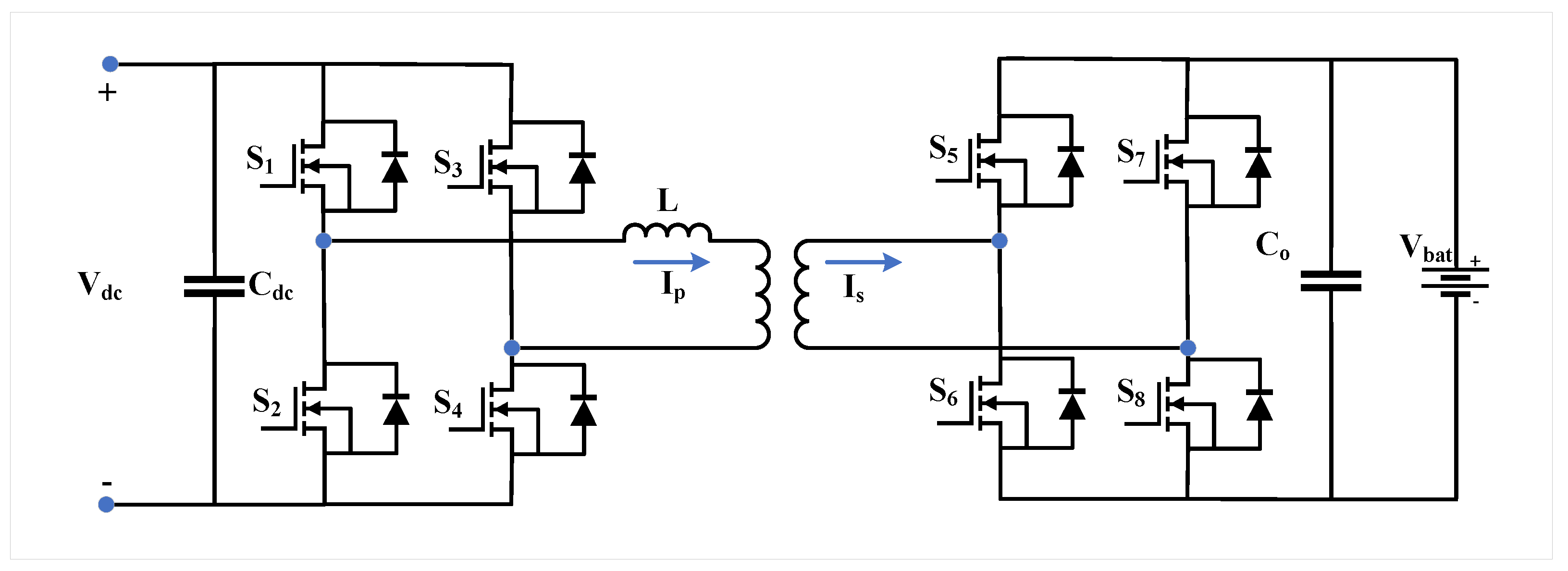
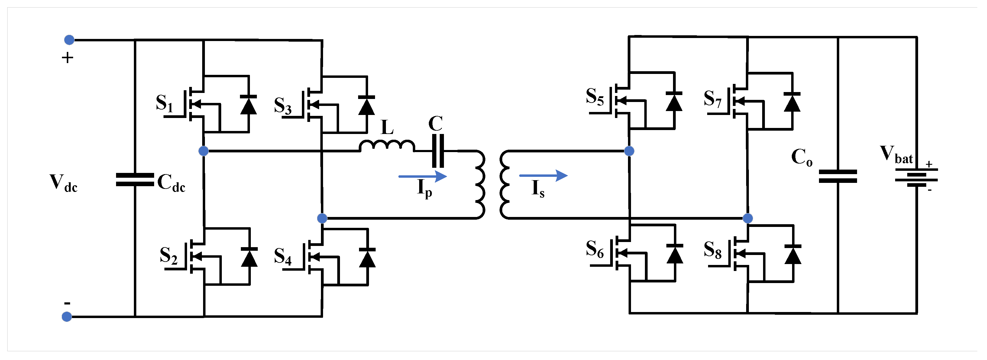
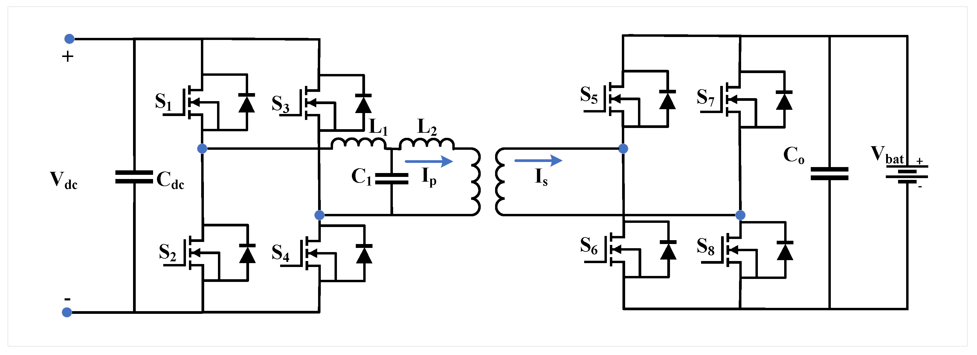
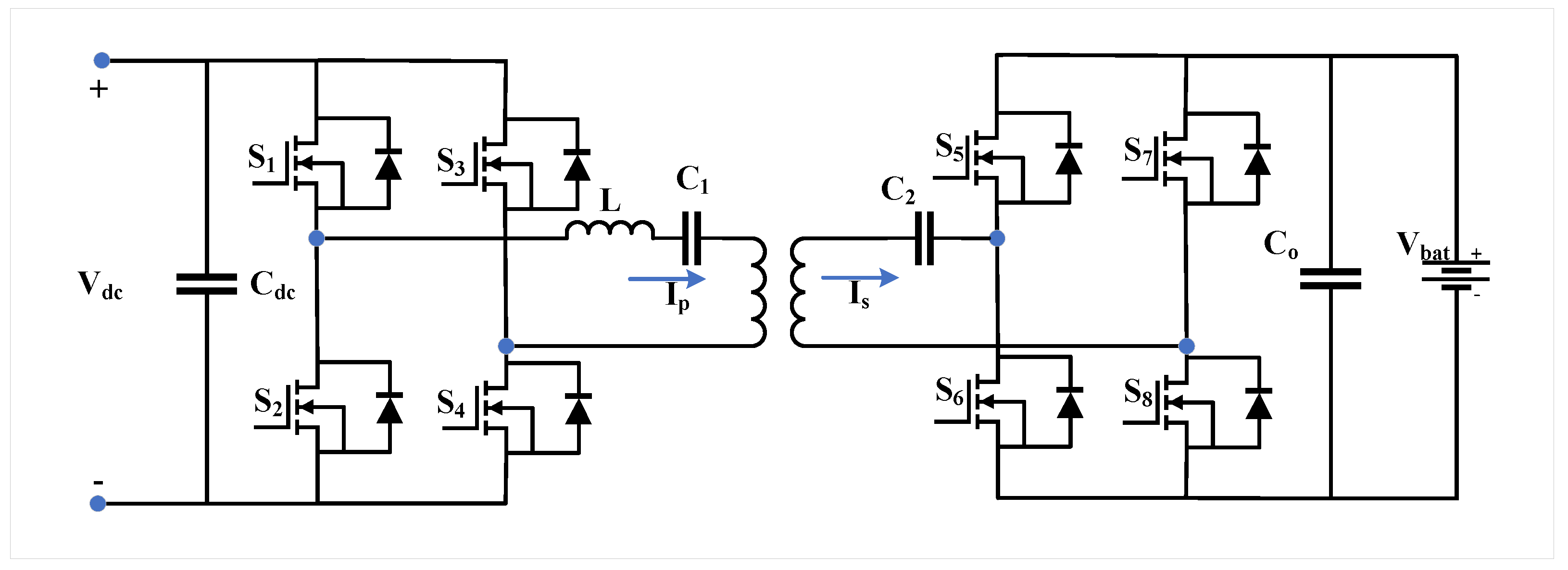
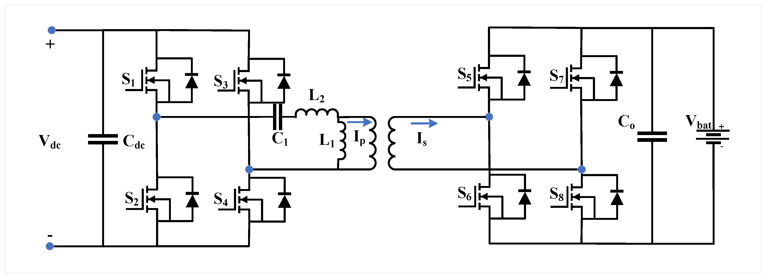
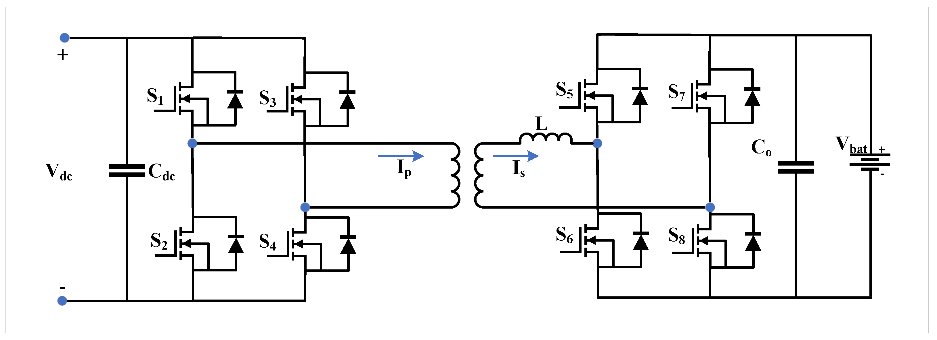
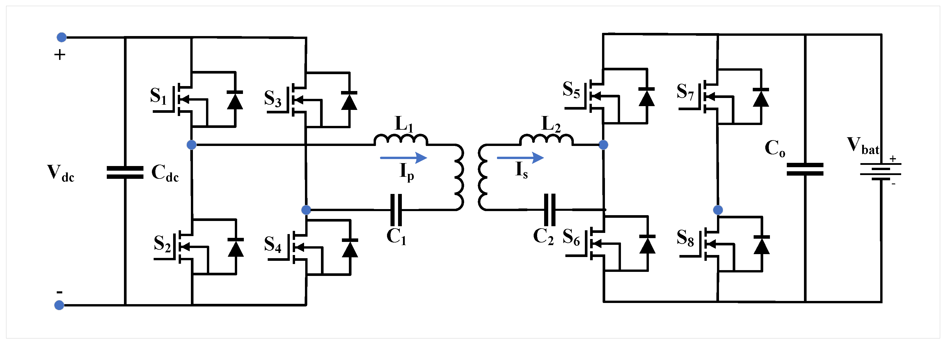
The Dual-Active-Bridge (DAB) converter allows bidirectional power transfer, high efficiency, step-up capability, low voltage stress, and compact size (Figure 21) [95]. Variants include resonant tank topologies: LC, LCL, CLC, LLL, and CLLC (Figure 22, Figure 23, Figure 24, Figure 25, Figure 26 and Figure 27) [109,110,111,112]. The Phase-Shifted full–bridge (PSFB) topology provides low EMI, soft-switching, and high power density (Figure 28) [113]. LLC-resonant variants further improve efficiency, power density, and voltage regulation [96,97,98,99].

4.2.2. Non-Isolated DC/DC Converters

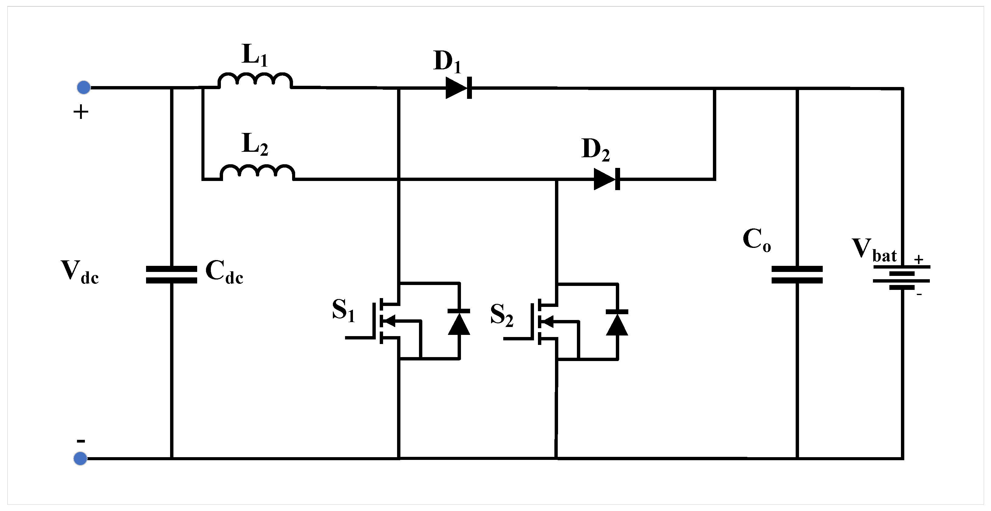
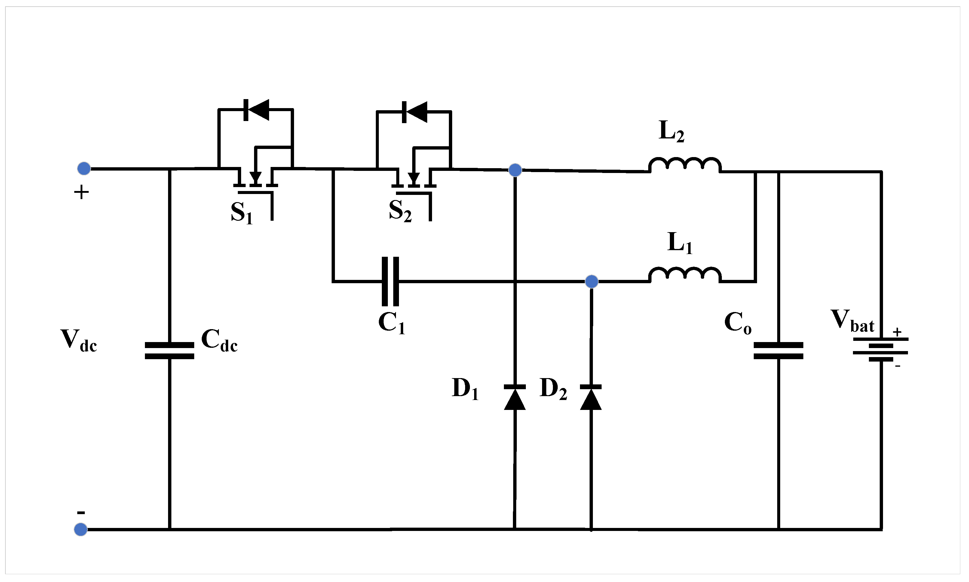
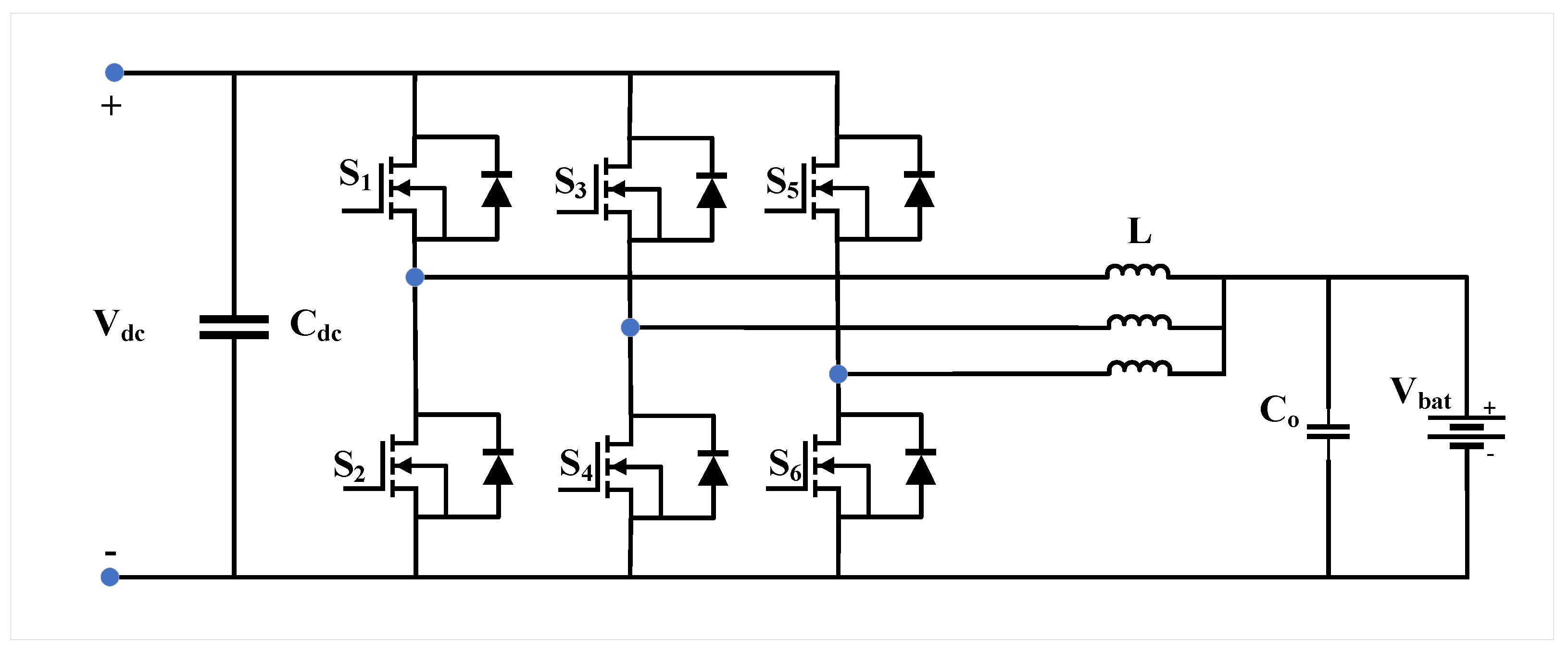
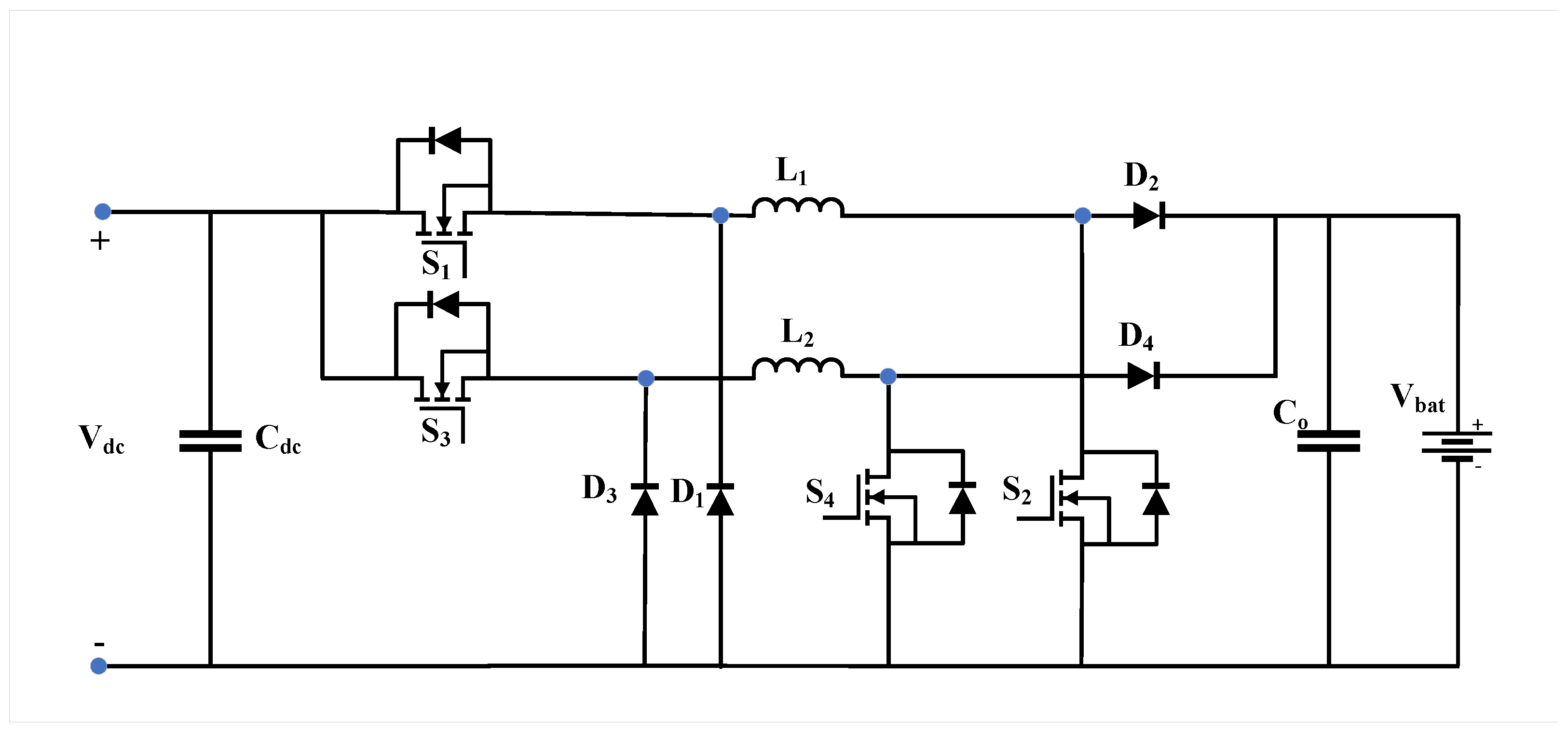
Non-isolated converters lack magnetic isolation but offer high power density, low cost, and simple structure [114,115]. Popular topologies include interleaved boost (Figure 29), two–phase buck (Figure 30), three–phase buck (Figure 31), and two–phase cascaded buck–boost (Figure 32) [100,101,102,103,104]. These architectures improve ripple, efficiency, and thermal performance while supporting bidirectional power flow.
Table 5 provides a comparison of DC/DC converter topologies for EV battery charging, emphasizing designs that utilize wide-bandgap (WBG) devices [116].

5. Power Flow

The power flow in EV charging systems can be classified into two categories: unidirectional (G2V) for battery charging and bidirectional (both G2V and V2G) for enabling both battery charging and grid-support services. In unidirectional G2V charging, an AC/DC rectifier is used on the grid side, while a unidirectional DC/DC converter is employed on the vehicle side within the on-board charger. This setup allows a relatively simple control strategy. In contrast, bidirectional systems enable energy transfer in both directions: from the grid to the vehicle during charging and from the vehicle battery back to the grid during discharge [117].
Most existing charging infrastructure operates in unidirectional G2V mode. This approach uses minimal hardware and simple control strategies to deliver electricity from the grid or local generation sources to the EV battery. It facilitates easier grid integration and helps mitigate battery degradation [13]. Unidirectional converters are often implemented in Single–stage configurations, reducing system weight, volume, cost, and power losses [118]. Moreover, active front-end unidirectional converters can provide reactive power compensation by adjusting the current phase angle without drawing energy from the battery. Large-scale deployment of unidirectional chargers satisfies grid requirements while avoiding the cost, safety, and reliability challenges associated with bidirectional solutions. Table 6 summarizes the differences between unidirectional and bidirectional charging systems.
V2G technology enables bidirectional energy exchange between EVs and the power grid, coordinated through communication protocols embedded in the charging infrastructure [119]. In this mode, EVs simultaneously act as distributed generation units, ESSs, and controllable loads. Recent studies highlight V2G’s value in ancillary service markets—particularly voltage regulation and spinning reserves—beyond simple peak load management.
Standardized V2G testing programs typically focus on three areas: battery performance, network operation, and system-level response. BEVs, with their large storage capacities, offer not only extended driving ranges but also greater potential for grid support. Future developments in V2G will rely on advancements in energy storage technologies, powertrain systems, and charging infrastructure. Comprehensive testing and development are essential to ensure V2G systems reliably contribute to grid stability and operational efficiency under real-world conditions [120].
The impact of EV charging on distribution network capacity is strongly influenced by the charging strategy employed [121]. In uncontrolled charging, EVs begin charging immediately upon connection to the grid, which can lead to substantial increases in peak electricity demand, overloading of distribution transformers, higher power losses, and voltage fluctuations within the network [122].
To mitigate these challenges, smart or coordinated charging strategies are used to manage the charging process based on grid conditions and user preferences [123]. By shifting charging to off-peak periods, these approaches reduce peak demand and improve the utilization of existing network infrastructure [124].
In addition, V2G technology provides further benefits by enabling EVs to supply stored energy back to the grid during periods of high demand [125]. This capability supports services such as peak load reduction and voltage regulation, thereby enhancing distribution network hosting capacity and reducing the need for costly infrastructure upgrades [121,122]. Overall, advanced charging strategies improve power quality, increase system reliability, and facilitate the large-scale integration of EVs into future power systems [122].

6. Renewable Energy Integration with EV Charging Stations

Integration of RES with EV charging systems is crucial for enabling clean, reliable, and cost-effective power for charging EV batteries. Moreover, RES integration benefits the power grid by reducing peak demand, minimizing transmission losses, and lowering overall energy transfer costs from generation to loads. EV charging systems are increasingly integrated with photovoltaic (PV) systems, wind energy, super-capacitors, and ESSs, with fuel cells emerging as a recent addition [126,127]. The availability of diverse RESs has led to the development of multiple EV charging system configurations. PV-based charging stations, in particular, have become more reliable due to recent technological advancements.
ESSs have emerged as essential components in RES-integrated EV charging infrastructure. For instance, Ref. [128] proposed a hybrid optimization algorithm for integrated EV charging stations combining PV systems and ESS, which minimizes overall charging costs by optimally scheduling energy flows between PV sources, ESS, and the grid while improving system efficiency and reliability. Similarly, Ref. [129] proposed an EV charging infrastructure integrating multiple energy sources, including the grid, PV, ESS, and a diesel generator (DG), to ensure uninterrupted charging availability. This hybrid configuration leverages PV generation for EVs, provides DG backup when PV and ESS are insufficient, and relies on grid connection to balance peak loads and enable bidirectional energy exchange. Compared to single-source charging solutions, such multi-source strategies improve system flexibility, cost-effectiveness, and reliability.
A decentralized adaptation integrating EV charging with wind power was presented in [130], using real-time coordinated control to balance charging demand with intermittent wind generation. This approach enhances energy utilization efficiency, reduces grid stress, and lowers overall charging costs. Smart coordination of EV charging systems to maximize RES utilization significantly alleviates grid burden while meeting most charging demand with clean energy sources. Such strategies enhance grid stability, reduce greenhouse gas emissions, and promote sustainable energy integration [131].
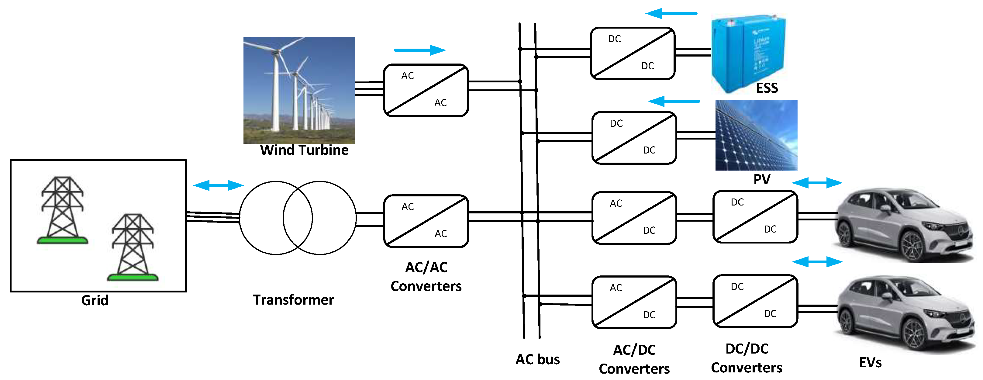
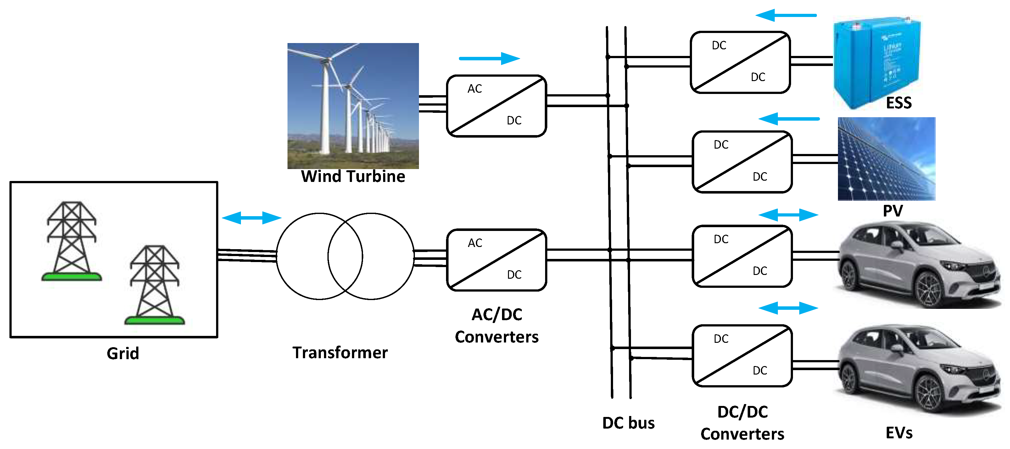
EV charging stations can be powered directly from the grid, RES, or hybrid combinations of both. The optimal choice depends on factors such as grid capacity and local availability, aiming to prevent overloads while maximizing charging efficiency through RES and battery storage. Many studies prioritize minimizing grid power draw during charging, which offers advantages such as reduced line losses, improved network efficiency, and enhanced reliability. Architectures of RES-integrated EV charging systems using a shared AC bus and a DC bus are illustrated in Figure 33 and Figure 34, respectively. These configurations typically combine the utility grid, PV panels, wind generation, ESS, and bidirectional EV charging/discharging capabilities, supported by suitable converters and control mechanisms.
RES-based charging systems are gaining popularity for several reasons. Integrating RES with EVs enables sustainable charging by directly powering vehicles with renewable energy, particularly during peak demand periods [20]. Solar PV-integrated EV charging systems reduce grid reliance and alleviate peak load pressures. EV batteries also serve as effective storage for PV generation, and declining solar installation costs have accelerated PV adoption [132]. Numerous studies show that coordinated operation of PV and EV systems can mitigate negative grid impacts associated with individual integration [133]. However, integrating EVs and RES with the grid remains challenging, requiring advanced planning, multiple conversion stages, and sophisticated control strategies. Without proper coordination, system stability could be compromised, severely impacting the distribution network [134]. Among the available options, RES-based common DC bus EV charging station (EVCS) architectures are extensively studied due to their superior efficiency, flexibility in integrating diverse energy sources, and advanced smart control capabilities [135].
On-board charging systems face inherent limitations in weight, volume, and physical size, which restricts their power transfer capacities to levels typically corresponding to Level 1 and Level 2 charging. These chargers (on-board and off-board) can operate in unidirectional or bidirectional modes and usually employ a two-stage power conversion architecture, consisting of an AC/DC converter on the grid side and a DC/DC converter on the vehicle battery side. The AC/DC rectifier stage commonly uses half-bridge, full–bridge, or multilevel topologies, which constrain the overall power transfer capability. Consequently, on-board chargers generally require longer charging times compared to off-board chargers, but off-board chargers can deliver higher power more rapidly [136].
Several studies have explored advanced control methods for on-board chargers to enhance grid support, controllability, and efficiency. For example, Ref. [137] introduced a compact single-phase on-board charger using a current oscillation compensation technique. The configuration employs a series arrangement of a zeta converter and a boost converter with the EV battery, eliminating the need for bulky passive components. In [138], a comparative study of wide band-gap devices for on-board chargers is presented, demonstrating a practical 400 V/80 A test bench using Si MOSFET components. A versatile on-board charger operating as both an AC/DC converter with PFC and a V2G converter, utilizing different inductors and switches, is presented in [139]. Additionally, a three–phase on-board charging system integrated with the EV propulsion system is studied in [140], featuring a 3.3 kW three–phase integrated charger with unity power factor, 92.6% efficiency, and THD reduced to 4.77%.
A literature review on integrated RES with on-board EV chargers is presented in [141]. The study models a DG, EV battery, wind turbine, PV system, single-phase grid (230 V, 50 Hz), and load. System controls include P&O MPPT for PV, PWM for inverter and boost converter, and constant current control for EV charging, validated through MATLAB (https://journal.esrgroups.org/jes/article/view/3740 (accessed on 15 April 2026)) simulations.
Similarly, Ref. [142] demonstrates that hybrid renewable charging stations combining PV arrays, wind turbines, and EVs can meet diverse EV power demands, reduce fossil fuel dependence, and enable cleaner transportation. Challenges such as renewable intermittency and infrastructure costs can be mitigated through energy storage, robust grid integration, and supportive policies.
In [143], a hybrid system comprising a 10 kW solar PV panel and a 10 kW biogas generator (20 kW total) is proposed, including standard charging assemblies and load management controls. A fuzzy logic-based energy management algorithm optimizes charging costs and maximizes renewable utilization. Results show cost reductions up to 74.67% compared to grid-only stations, greenhouse gas emissions reduction of 54.86%, and support for 4–20 vehicles. Similarly, Ref. [144] explores RES integration with EV systems into smart grids using bidirectional charging, highlighting improved grid reliability and sustainable energy adoption. Ref. [145] demonstrated models of grid connections with RES and PHEVs across three scenarios: grid only, grid with PHEV, and grid with PHEV plus RES, demonstrating improved reactive power management, maintained voltage profiles, reduced grid dependence, and stable operation.
Recent research has increasingly emphasized the integration of RES into off-board EV charging infrastructures to enhance transportation sustainability and alleviate stress on power grid systems. In [146], an efficient PV-integrated multifunctional off-board EV charger was proposed to improve grid power quality. The charger uses a reduced-switch topology, which simplifies the converter structure and helps increase the overall efficiency. In [147], an experimentally validated EV charging station with a reduced switch count converter topology was introduced. The design was focused on minimizing the number of active switches to reduce complexity, cost, and switching losses, without sacrificing reliability.
There are numerous benefits of using RESs, particularly solar PV panels, in EV charging infrastructures. First, they can decrease reliance on fossil fuels, lower greenhouse gas emissions, and improve the environmental friendliness of EV charging stations. Second, by depending on locally generated clean energy, they also increase energy security and can eventually reduce electricity bills by relieving demand on the main grid. Furthermore, solar-powered charging is particularly useful in isolated locations or areas with poor grid connectivity, where it may be costly or difficult to construct traditional charging stations [20].
However, there are also important challenges of using RESs in charging systems. Solar power is not always available, since its output depends on weather conditions, time of day, and season. Because of this, charging systems often need energy storage, smart control systems, or backup grid power to operate reliably. Another major challenge is the high initial cost of solar panels, power electronics inverters, batteries, and other supporting equipment. Grid integration can also be complicated, since many solar-powered chargers may cause voltage and frequency fluctuations if they are not properly managed [148].
The environmental effects are largely positive. Charging EVs with renewable energy sources can significantly reduce carbon emissions and air pollution compared with charging from fossil-fuel-based electricity. It also supports the move toward cleaner urban transport and reduces reliance on imported oil. Even so, the overall environmental benefit ultimately depends on how effectively the system is designed and managed. Without careful planning of energy storage, control strategies, and grid integration, part of the expected environmental gains may be offset by inefficiencies and additional infrastructure requirements [20].
Despite significant advancements in EV charging technologies, the practical deployment of charging infrastructure remains associated with several technical, economic, and operational challenges. The installation of EV charging stations requires considerable capital investment, including equipment procurement, grid connection, land acquisition, and civil engineering costs. In addition, maintenance expenses related to charger reliability, communication systems, and periodic component replacement can significantly affect the long-term economic viability of charging networks [149]. Safety considerations are equally important, requiring compliance with electrical protection standards, thermal management, and fault detection measures to ensure reliable operation. Furthermore, the widespread adoption of fast-charging stations imposes substantial stress on distribution networks, potentially leading to transformer overloading, voltage fluctuations, increased power losses, and the need for grid reinforcement [149]. Consequently, effective charging station planning should consider not only charging demand but also grid capacity, traffic patterns, user behavior, renewable energy integration, and smart charging strategies to optimize infrastructure utilization and minimize adverse impacts on the power system [150]. A comprehensive planning framework that balances installation cost, maintenance requirements, safety, and grid constraints is therefore essential for the sustainable expansion of EV charging infrastructure [150,151].

7. Future Trends and Challenges

EVs are expanding rapidly and are playing a central role in the ongoing transformation of the transportation sector. While this transition contributes to the reduction of greenhouse gas emissions, it also introduces significant challenges for electrical distribution networks. Among the most frequently cited concerns are limited driving range, relatively long charging durations compared with conventional refueling, high acquisition costs, and uncertainties related to battery durability. For this reason, continuous assessment of emerging technologies, innovative control strategies, and future EV charging paradigms is essential to improve system efficiency and ensure reliable integration with modern power grids [16].
Forecasts reported by the U.S. Department of Energy [152] suggest that substantial technological progress is expected in the coming years. Battery energy densities are projected to approach approximately 35,000 Wh/L, while the operational lifetime of EV batteries could exceed 500,000 km, corresponding to roughly 16 years of usage. These improvements are partly attributed to the ongoing development of solid-state battery technologies. At the same time, BEVs are becoming dominant in newly fabricated vehicles. Modular design approaches adopted by manufacturers provide greater flexibility, improve system performance, and contribute to cost reductions estimated at approximately 15–20% [153].
Furthermore, over-the-air software updates allow vehicle manufacturers to remotely upgrade and modify embedded software without requiring physical intervention [154,155]. This capability enables continuous improvement of vehicle performance throughout its lifetime. In particular, it can be used to refine energy management strategies, enhance control algorithms, and optimize the operation of key subsystems such as battery management and power electronics. In addition, it allows the deployment of new functionalities after vehicle delivery, including improved driver assistance features, updated infotainment services, and enhanced user interfaces.
Beyond functional upgrades, over-the-air technology also plays an important role in maintenance and reliability. It enables rapid correction of software bugs, implementation of safety improvements, and mitigation of cybersecurity vulnerabilities, thereby reducing the need for service visits or hardware recalls. As a result, the vehicle becomes a more flexible and adaptive system, capable of evolving over time in response to user needs, regulatory requirements, and technological advancements.
Rapid progress is also observed in charging infrastructure, where ultra-fast charging stations rated between 350 kW and 800 kW aim to approach the refueling convenience of conventional ICE vehicles while employing artificial intelligence (AI) techniques for load optimization and dynamic pricing [156].
Wireless Power Transfer (WPT) and V2G technologies are transforming EV charging by enabling greater convenience, automation and grid interaction. Resonant inductive coupling enables contactless charging, reducing maintenance requirements and facilitating usability in residential and workplace environments [157]. Meanwhile, V2G systems enable two-way energy flow, allowing EVs to support the grid during peak demand and even generate additional revenue for users [158]. In addition, advances in BMS and machine learning integration improve the accuracy of SoC estimation and extend battery life. Additional innovations in the Internet of Vehicles (IoV) and 5G-related frameworks enable real-time intelligent vehicle communication, resulting in better energy efficiency and mobility services [159]. Integrating RESs such as solar and wind with energy storage and AI-based energy management systems will increase grid resilience and promote sustainable EV charging infrastructures.
Current Trends and Perspectives: Today’s EV ecosystem is rapidly evolving, with ultra-fast charging stations, expanding V2G services, and the rise of wireless charging. Researchers are exploring smart energy management, AI-driven charging optimization, and advanced battery technologies that offer higher capacity and longer life. These innovations are making charging more convenient, enhancing grid stability, and promoting sustainability, hence providing a clear outlook on the future of EV systems and renewable energy integration. Several emerging trends are set to shape the future of electric EV charging:
  • Dynamic WPT on roads: Charging while driving on specially equipped roads, allowing EVs to operate with smaller batteries and reducing the need for stops.
  • High-efficiency resonant systems: Improved coil designs and intelligent control strategies that maintain efficiency above 90%, even if the vehicle is not perfectly aligned.
  • Renewable-energy EV microgrids: Integration of solar and wind energy at charging stations with direct battery connections to provide cost-effective and efficient power.
  • V2G/V2X bidirectional energy flow: EVs contributing to grid stability by storing surplus renewable energy and feeding it back when needed, with AI optimizing the timing.
  • Solid-state batteries: Advanced batteries offering higher energy density, ultra-fast charging, and improved safety under frequent wireless or solar top-ups.
  • Smart battery management systems (BMS): Real-time monitoring of battery health and adaptive charging based on the availability of wireless power and renewable energy.

8. Summary and Conclusions

The rapid growth of EV adoption has been driven by continuous advancements in charging infrastructure, battery technologies, and power electronic converters. This review has comprehensively examined EV classifications, charging standards, charging station architectures, charging techniques, charging control strategies, converter topologies, and the integration of RESs into EV charging systems. In addition, the interactions between EV charging infrastructures and electrical distribution networks have been discussed, highlighting their role in supporting future sustainable transportation systems.
The findings of this review indicate that AC charging technologies are well suited for residential and workplace applications, whereas DC fast and ultra-fast charging architectures are essential for commercial and public charging infrastructures. Market trends demonstrate the rapid expansion of EV adoption, with global EV sales reaching approximately 16.5 million units in the first half of 2024 and China, Europe, and the USA accounting for nearly 95% of the global market [4]. Furthermore, recent developments in charging infrastructure and power electronics have enabled higher charging powers while improving overall system efficiency.
Power electronic converter technologies remain a key enabling factor for advanced EV charging systems. Among the reviewed topologies, MMC structures provide excellent scalability and high efficiency for high-power applications, while DAB and CLLC converters offer efficient isolated DC/DC conversion for fast-charging stations. The adoption of wide-bandgap semiconductor devices, particularly SiC and GaN technologies, has significantly improved converter efficiency, switching performance, and power density, with reported efficiencies approaching 99% for advanced converter topologies. These improvements support the implementation of ultra-fast charging stations and facilitate the effective integration of renewable energy sources into EV charging infrastructures.
The review also highlights the importance of battery charging control strategies, including CC–CV and CP–CV methods combined with PI, MPC, SMC, and FLC controllers, for improving charging performance, reducing battery degradation, and enhancing operational safety. In addition, renewable-energy-powered charging stations offer significant environmental and economic benefits by reducing greenhouse gas emissions, lowering operating costs, and increasing energy sustainability. Previous studies have reported considerable reductions in both operating costs and emissions through renewable-integrated EV charging systems [143].
Despite these advances, several technical challenges continue to limit the large-scale deployment of EV charging technologies. Grid congestion, battery driving range limitations, renewable energy intermittency, communication requirements, and the commercial implementation of V2G systems remain important issues. Although V2G and renewable-integrated charging stations provide significant opportunities for enhancing grid flexibility and energy management, their practical deployment requires further improvements in bidirectional power converters, battery management systems, communication protocols, and system interoperability.
Future research should focus on the development of highly efficient bidirectional converter topologies, broader adoption of wide-bandgap semiconductor devices, intelligent charging and energy management strategies, advanced V2G technologies, standardized communication protocols such as ISO 15118-20, and enhanced integration of renewable energy and energy storage systems. These developments will contribute to the realization of reliable, efficient, and sustainable EV charging infrastructures capable of supporting the continued global electrification of transportation.


Author Contributions

Conceptualization, A.A., A.E.A. and H.V.-B.; methodology, A.A., A.E.A. and H.V.-B.; visualization, A.A., A.E.A. and H.V.-B.; writing—original draft preparation, A.A.; writing—review and editing, A.E.A. and H.V.-B. All authors have read and agreed to the published version of the manuscript.

Funding

This work was supported in part by MICIU/AEI/10.13039/501100011033 through the Spanish Ministry of Science and Innovation under Grant PID2023-150839OB-I00.

Data Availability Statement

Not applicable.

Conflicts of Interest

The authors declare no conflicts of interest.

Abbreviations

The following abbreviations are used in this manuscript:
EVElectric Vehicle
AEVAll-Electric Vehicle
HEVHybrid Electric Vehicle
PHEVPlug-in Hybrid Electric Vehicle
EREVExtended Range Electric Vehicle
BEVBattery Electric Vehicle
FCEVFuel Cell Electric Vehicle
ICEInternal Combustion Engine
IEAInternational Energy Agency
BNEFBloombergNEF
C O 2 Carbon Oxide
BMSBattery Management System
RESRenewable Energy Sources
PVPhotovoltaic
ESSEnergy Storage System
DGDiesel Generator
ACAlternating Current
DCDirect Current
CCSCombined Charging System
CHAdeMOCharge de Move (Japanese fast charging standard)
OCPPOpen Charge Point Protocol
SAESociety of Automotive Engineers
IEEEInstitute of Electrical and Electronics Engineers
IECInternational Electrotechnical Commission
SACStandardization Administration of China
GBTGuoBiao Standard (Chinese National Standard)
PFCPower Factor Correction
THDTotal Harmonic Distortion
NPCNeutral Point Clamped
CHBCascaded H–Bridge
MMCModular Multilevel Converter
PSFBPhase-Shifted Full Bridge
ZVSZero-Voltage Switching
ZCSZero-Current Switching
SiCSilicon Carbide
GaNGallium Nitride
WPTWireless Power Transfer
IPTInductive Power Transfer
CPTCapacitive Power Transfer
RIPTResonant Inductive Power Transfer
EMFElectromagnetic Field
BSSBattery Swapping Station
G2VGrid to Vehicle
V2GVehicle to Grid
SoCState of Charge
IoVInternet of Vehicles
WBGWide-Bandgap
MPCModel Predictive Control
SMCSliding Mode Control
CC–CVConstant Current–Constant Voltage
CP–CVConstant Power–Constant Voltage

References

  1. Hwang, F.S.; Confrey, T.; Reidy, C.; Picovici, D.; Callaghan, D.; Culliton, D.; Nolan, C. Review of battery thermal management systems in electric vehicles. Renew. Sustain. Energy Rev. 2024, 192, 114171. [Google Scholar] [CrossRef]
  2. El Kassar, R.; Al Takash, A.; Faraj, J.; Hammoud, M.; Khaled, M.; Ramadan, H.S. Recent advances in lithium-ion battery integration with thermal management systems for electric vehicles: A summary review. J. Energy Storage 2024, 91, 112061. [Google Scholar] [CrossRef]
  3. Veysi, S.; Moshfeghi, M.; Sadrfaridpour, A.; Emamy, P. Electric Vehicle Sales Forecast for the UK: Integrating Machine Learning, Time Series Models, and Global Trends. Algorithms 2025, 18, 430. [Google Scholar] [CrossRef]
  4. EV-Volumes. Is the global EV Market Slowing Down? 2024. Available online: https://ev-volumes.com/news/ev/is-the-global-ev-market-slowing-down/ (accessed on 25 July 2025).
  5. International Energy Agency (IEA). Global EV Outlook 2025; Technical Report; International Energy Agency: Paris, France, 2025; Available online: https://iea.blob.core.windows.net/assets/0aa4762f-c1cb-4495-987a-25945d6de5e8/GlobalEVOutlook2025.pdf (accessed on 15 April 2026).
  6. BloombergNEF. Electric Vehicle Outlook 2025; Technical Report; BloombergNEF: London, UK, 2025; Available online: https://about.bnef.com/insights/clean-transport/electric-vehicle-outlook/ (accessed on 30 July 2025).
  7. Yong, J.Y.; Ramachandaramurthy, V.K.; Tan, K.M.; Mithulananthan, N. A review on the state-of-the-art technologies of electric vehicle, its impacts and prospects. Renew. Sustain. Energy Rev. 2015, 49, 365–385. [Google Scholar] [CrossRef]
  8. Bhatti, A.R.; Salam, Z.; Aziz, M.J.B.A.; Yee, K.P.; Ashique, R.H. Electric vehicles charging using photovoltaic: Status and technological review. Renew. Sustain. Energy Rev. 2016, 54, 34–47. [Google Scholar] [CrossRef]
  9. Ahmad, A.; Alam, M.S.; Chabaan, R. A Comprehensive Review of Wireless Charging Technologies for Electric Vehicles. IEEE Trans. Transp. Electrif. 2018, 4, 38–63. [Google Scholar] [CrossRef]
  10. Mahmud, K.; Town, G.E.; Morsalin, S.; Hoss, J.M. Integration of electric vehicles and management in the internet of energy. Renew. Sustain. Energy Rev. 2018, 82, 4179–4203. [Google Scholar] [CrossRef]
  11. SAE J1772_202401; SAE Electric Vehicle and Plug-in Hybrid Electric Vehicle Conductive Charge Coupler. SAE International: Warrendale PA, USA, 2024. Available online: https://www.sae.org/standards/content/j1772_202401/ (accessed on 31 July 2025).
  12. Rafi, M.A.H.; Bauman, J. A Comprehensive Review of DC Fast-Charging Stations with Energy Storage: Architectures, Power Converters, and Analysis. IEEE Trans. Transp. Electrif. 2021, 7, 345–368. [Google Scholar] [CrossRef]
  13. Kumar, S.; Usman, A.; Rajpurohit, B.S. Battery charging topology, infrastructure, and standards for electric vehicle applications: A comprehensive review. IET Energy Syst. Integr. 2021, 3, 381–396. [Google Scholar] [CrossRef]
  14. Wu, Y.; Wang, Z.; Huangfu, Y.; Ravey, A.; Chrenko, D.; Gao, F. Hierarchical Operation of Electric Vehicle Charging Station in Smart Grid Integration Applications—An Overview. Int. J. Electr. Power Energy Syst. 2022, 139, 108005. [Google Scholar] [CrossRef]
  15. Safayatullah, M.; Elrais, M.T.; Ghosh, S.; Rezaii, R.; Batarseh, I. A comprehensive review of power converter topologies and control methods for electric vehicle fast charging applications. IEEE Access 2022, 10, 40753–40793. [Google Scholar] [CrossRef]
  16. Acharige, S.S.; Haque, M.E.; Arif, M.T.; Hosseinzadeh, N.; Hasan, K.N.; Oo, A.M.T. Review of electric vehicle charging technologies, standards, architectures, and converter configurations. IEEE Access 2023, 11, 41218–41255. [Google Scholar] [CrossRef]
  17. IEC 61851; Electric Vehicle Conductive Charging System. International Electrotechnical Commission (IEC): Geneva, Switzerland, 2021. Available online: https://www.iec.ch/ (accessed on 31 July 2025).
  18. Manoj, V.; Pilla, R.; Sura, S.R. A comprehensive analysis of power converter topologies and control methods for extremely fast charging of electric vehicles. In Journal of Physics: Conference Series; IOP Publishing: Bristol, UK, 2023; Volume 2570, p. 012017. [Google Scholar] [CrossRef]
  19. Saraswathi, V.N.; Ramachandran, V.P. A comprehensive review on charger technologies, types, and charging stations models for electric vehicles. Heliyon 2024, 10, e38945. [Google Scholar] [CrossRef] [PubMed]
  20. Tripathi, A.K.; Sree Lakshmi, G.; Mishra, H.; Chapala, S.; Alwetaishi, M.; Atamurotov, F.; Benti, N.E.; Sura, S.; Ahamed Saleel, C. Integration of Solar PV Panels in Electric Vehicle Charging Infrastructure: Benefits, Challenges, and Environmental Implications. Energy Sci. Eng. 2025, 13, 2135–2152. [Google Scholar] [CrossRef]
  21. Abbas, M.Q.; Aarniovuori, L.; Peltoniemi, P.; Mengoni, M.; Zarri, L. Integrated On-Board Chargers for Electric Vehicles: Topologies, Control Strategies, Challenges, and Future Research Directions. IEEE Access 2026, 11, 54511–54540. [Google Scholar] [CrossRef]
  22. Kusuma, I.; Kusumoputro, R.; Iswadi, A.; Iswadi, A. Electric Vehicle Review: BEV, PHEV, HEV, or FCEV? J. Konv. Ener. Manuf. 2025, 10, 70–83. [Google Scholar]
  23. U.S. Department of Energy. Electric Vehicles: Benefits and Considerations. 2023. Available online: https://www.energy.gov/eere/electricvehicles/electric-vehicles (accessed on 28 July 2025).
  24. Toyota Motor Corporation. Toyota Mirai—Interior Gallery. 2025. Available online: https://www.toyota.com/mirai/section/gallery/tab/interior/ (accessed on 29 July 2025).
  25. Hyundai Motor Company. Hyundai NEXO—Highlights. 2025. Available online: https://www.hyundai.com/worldwide/en/eco/nexo/highlights (accessed on 29 July 2025).
  26. Toyota Motor Corporation. Toyota Prius-Official Site. Available online: https://www.toyota.com/prius/ (accessed on 30 July 2025).
  27. BMW, UK. BMW Electric Cars—Models and Information. 2025. Available online: https://www.bmw.co.uk/en/electric-cars.html (accessed on 30 July 2025).
  28. CHAdeMO Association. CHAdeMO Technical Specifications. 2023. Available online: https://www.chademo.com/ (accessed on 31 July 2025).
  29. Institute of Electrical and Electronics Engineers (IEEE). Standards for Electric Vehicle Charging Infrastructure. 2022. Available online: https://standards.ieee.org (accessed on 31 July 2025).
  30. Standardization Administration of China (SAC). GB/T Standards for EV Charging. 2020. Available online: http://www.sac.gov.cn/ (accessed on 31 July 2025).
  31. IEC 61851-1:2017; Electric Vehicle Conductive Charging System—Part 1: General Requirements. International Electrotechnical Commission (IEC): Geneva, Switzerland, 2017. Available online: https://webstore.iec.ch/en/publication/33644 (accessed on 20 July 2025).
  32. Tesla, Inc. Opening the North American Charging Standard (NACS), 2022. Available online: https://www.tesla.com/blog/opening-north-american-charging-system (accessed on 20 July 2025).
  33. IEC 62196-3:2022; Plugs, Socket-Outlets, Vehicle Connectors and Vehicle Inlets—Conductive Charging of Electric Vehicles—Part 3: Dimen-Sional Compatibility and Interchangeability Requirements for d.c. and a.c./d.c. Pin and Contact-Tube Vehicle Couplers. International Electrotechnical Commission (IEC): Geneva, Switzerland, 2022. Available online: https://webstore.iec.ch/en/publication/59922 (accessed on 31 July 2025).
  34. ISO 15118-20:2022; Road vehicles—Vehicle to Grid Communication Interface—Part 20: 2nd Generation Network Layer and Application Layer Requirements. International Organization for Standardization: Geneva, Switzerland, 2022.
  35. SAE J2954; Wireless Power Transfer for Light-Duty Plug-in/Electric Vehicles and Alignment Methodology. SAE International: Warrendale PA, USA, 2022.
  36. Malik, F.H.; Lehtonen, M.; Saarijärvi, E.; Safdarian, A. A Feasibility Study of Fast Charging Infrastructure for EVs on Highways. Int. Rev. Electr. Eng. 2014, 9, 341. [Google Scholar]
  37. Deb, S.; Tammi, K.; Kalita, K.; Mahanta, P. Impact of Electric Vehicle Charging Station Load on Distribution Network. Energies 2018, 11, 178. [Google Scholar] [CrossRef]
  38. Yoldaş, Y.; Önen, A.; Muyeen, S.; Vasilakos, A.V.; Alan, İ. Enhancing smart grid with microgrids: Challenges and opportunities. Renew. Sustain. Energy Rev. 2017, 72, 205–214. [Google Scholar] [CrossRef]
  39. Arababadi, R.; Moslehi, S.; El Asmar, M.; Haavaldsen, T.; Parrish, K. Energy policy assessment at strategic, tactical, and operational levels: Case studies of EU 20-20-20 and U.S. Executive Order 13514. Energy Policy 2017, 109, 530–538. [Google Scholar] [CrossRef]
  40. Alamelu, R.; Rengarajan, V.; Dinesh, S.; Nalini, R.; Shobhana, N.; Amudha, R. Sustainable supply chain practices with reverse innovation in healthcare start-ups—A Structural Equation Model (SEM) approach. Mater. Today Proc. 2022, 52, 882–887. [Google Scholar] [CrossRef]
  41. Lebrouhi, B.; Khattari, Y.; Lamrani, B.; Maaroufi, M.; Zeraouli, Y.; Kousksou, T. Key challenges for a large-scale development of battery electric vehicles: A comprehensive review. J. Energy Storage 2021, 44, 103273. [Google Scholar] [CrossRef]
  42. Reuters. Reuters. Electric Car Maker Tesla Unveils 90-Second Battery Pack Swap. 2013. Available online: https://www.reuters.com/article/us-tesla-swap/electric-car-maker-tesla-unveils-90-second-battery-pack-swap-idUSBRE95K07H20130621/ (accessed on 5 August 2025).
  43. Sun, B.; Tan, X.; Tsang, D.H.K. Optimal Charging Operation of Battery Swapping and Charging Stations with QoS Guarantee. IEEE Trans. Smart Grid 2018, 9, 4689–4701. [Google Scholar] [CrossRef]
  44. Wu, H. A survey of battery swapping stations for electric vehicles: Operation modes and decision scenarios. IEEE Trans. Intell. Transp. Syst. 2021, 23, 10163–10185. [Google Scholar] [CrossRef]
  45. Li, C.; Wang, N.; Li, W.; Yi, Q.; Qi, D. A battery centralized scheduling strategy for battery swapping of electric vehicles. J. Energy Storage 2022, 51, 104327. [Google Scholar] [CrossRef]
  46. Rabih, M.; Takruri, M.; Al-Hattab, M.; Alnuaimi, A.A.; Bin Thaleth, M.R. Wireless charging for electric vehicles: A survey and comprehensive guide. World Electr. Veh. J. 2024, 15, 118. [Google Scholar] [CrossRef]
  47. Mohamed, A.A.S.; Mohammed, O. Physics-Based Co-Simulation Platform with Analytical and Experimental Verification for Bidirectional IPT System in EV Applications. IEEE Trans. Veh. Technol. 2018, 67, 275–284. [Google Scholar] [CrossRef]
  48. Ahmed, M.M.; Enany, M.A.; Shaier, A.A.; Bawayan, H.M.; Hussien, S.A. An extensive overview of inductive charging technologies for stationary and in-motion electric vehicles. IEEE Access 2024, 12, 69875–69894. [Google Scholar] [CrossRef]
  49. Alabsi, A.; Hawbani, A.; Wang, X.; Al-Dubai, A.; Hu, J.; Aziz, S.A.; Kumar, S.; Zhao, L.; Shvetsov, A.V.; Alsamhi, S.H. Wireless power transfer technologies, applications, and future trends: A review. IEEE Trans. Sustain. Comput. 2024, 10, 1–17. [Google Scholar] [CrossRef]
  50. Driivz. 2026 EV Charging Industry Predictions and Trends. 2026. Available online: https://driivz.com/blog/2026-ev-charging-industry-predictions-and-trends/ (accessed on 8 March 2026).
  51. Zentani, A.; Almaktoof, A.; Kahn, M.T. A comprehensive review of developments in electric vehicles fast charging technology. Appl. Sci. 2024, 14, 4728. [Google Scholar] [CrossRef]
  52. Leijon, J. Charging strategies and battery ageing for electric vehicles: A review. Energy Strategy Rev. 2025, 57, 101641. [Google Scholar] [CrossRef]
  53. NextBillion.ai. AI-Driven Strategies for Optimizing EV Charging Networks. 2025. Available online: https://nextbillion.ai/blog/ai-optimizing-ev-charging-networks (accessed on 8 March 2026).
  54. Mammeri, E.N.; Lopez-Santos, O.; Aroudi, A.E.; Martinez-Salamero, L. Constant-Power Constant-Voltage Charging Protocol Based on a Four-Phase Interleaved Buck Converter for Electric Vehicle Batteries. In Proceedings of the IEEE International Symposium on Circuits and Systems (ISCAS), London, UK; IEEE: Piscataway, NJ, USA, 2025; pp. 1–5. [Google Scholar]
  55. Saeed, M.; Khalatbarisoltani, A.; Deng, Z.; Liu, W.; Altaf, F.; Lu, S.; Hu, X. Comparative Analysis of Control Observer-Based Methods for State Estimation of Lithium-Ion Batteries in Practical Scenarios. IEEE/ASME Trans. Mechatron. 2025, 30, 3697–3709. [Google Scholar] [CrossRef]
  56. Sohail, M.; Saeed, M.; Khalatbarisoltani, A.; Jawaad, H.M.; Ge, L. An Intelligent Control-Based Charging Strategy for Lithium-Ion Batteries. In Proceedings of the IEEE 16th International Symposium on Power Electronics and Distributed Generation Systems (PEDG); IEEE: Piscataway, NJ, USA; pp. 1–6.
  57. Seth, A.K.; Singh, M. Plant integrated proportional integrating based control design for electric vehicle charger. Comput. Electr. Eng. 2023, 105, 108522. [Google Scholar] [CrossRef]
  58. Krishnapriya, T.K. A Revised PI Controller for High Current Density DC-DC Conversion Utilising Six Switches to Improve EV Charging Efficiency. In Proceedings of the 2nd International Conference on Smart Innovations in Electrical Engineering (ICSIEE 2025); IEEE: Piscataway, NJ, USA, 2025; p. 23. [Google Scholar]
  59. Natarajan, R.; Selvaraj, J.; Daniel, S.; Mekonnen Azerefegn, T. Optimized PI controller-based hybrid model for adaptive energy management in photovoltaic integrated electric vehicle charging microgrids. Sci. Rep. 2026, 16, 10341. [Google Scholar] [CrossRef] [PubMed]
  60. Yadav, I.C.; Bajpai, R.S.; Gupta, S.; Shukla, A. Hybrid fuzzy-MPC based multi-objective control strategy for fast charging of electric vehicles with advanced battery thermal management and renewable grid support. Sci. Rep. 2025, 15, 42342. [Google Scholar] [CrossRef] [PubMed]
  61. Ahmed, M.U.; Qays, M.O.; Lachowicz, S.; Mahmud, P. Optimizing EV Battery Charging Using Fuzzy Logic in the Presence of Uncertainties and Unknown Parameters. Electronics 2025, 15, 177. [Google Scholar] [CrossRef]
  62. Zaineb, A.; Vijayasanthi, M.; Mandadi, P.N. Fuzzy logic controller based charging and discharging control for battery in EV applications. Int. J. Electr. Electron. Res. 2024, 12, 1–7. [Google Scholar] [CrossRef]
  63. Mehrasa, M.; Razi, R.; Hajar, K.; Labonne, A.; Hably, A.; Bacha, S. Power management of a smart vehicle-to-grid (V2G) system using fuzzy logic approach. In IECON 2021–47th Annual Conference of the IEEE Industrial Electronics Society; IEEE: Piscataway, NJ, USA, 2021; pp. 1–6. [Google Scholar]
  64. López-Santos, O.; Flores-Bahamonde, F.; Torres-Pinzón, C.A.; Haroun, R.; Valderrama-Blavi, H.; Garriga, J.A.; Martínez-Salamero, L. Multi-loop sliding-mode control for a battery charger using a quadratic buck converter. In 2023 IEEE 8th Southern Power Electronics Conference and 17th Brazilian Power Electronics Conference (SPEC/COBEP); IEEE: Piscataway, NJ, USA, 2023; pp. 1–6. [Google Scholar]
  65. Valedsaravi, S.; Mandal, K.; El Aroudi, A.; Martínez-Salamero, L. Digital sliding mode control of a 3-phase ac-dc rectifier for ultra-fast charging of EV battery. IFAC-PapersOnLine 2024, 58, 430–435. [Google Scholar]
  66. Akin, B.; Taşcıkaraoglu, A.; Catalão, J.P.S. Sliding Mode-Based Control of an Electric Vehicle Fast Charging Station Integrated into a Microgrid. Sustain. Energy Grids Netw. 2023, 36, 101201. [Google Scholar] [CrossRef]
  67. Wang, Y.; Zhong, N.; Zhang, M. Sliding Mode Control Design of Battery Energy Storage Charging System Based on Isolated DC-DC Converter. Chem. Eng. Trans. 2020, 81, 187–192. [Google Scholar]
  68. Gul, B.T.; Rehman, A.; Sherazi, H.I.; Alburidy, A.; Alsafrani, A.; Alrumayh, O. Optimal control strategy for electric vehicle powered by PV arrays and battery using LQR and SMC controllers. Sci. Rep. 2025, 15, 30545. [Google Scholar] [CrossRef] [PubMed]
  69. Ehsani, M.; Singh, K.V.; Bansal, H.O.; Mehrjardi, R.T. State of the Art and Trends in Electric and Hybrid Electric Vehicles. Proc. IEEE 2021, 109, 967–984. [Google Scholar] [CrossRef]
  70. Piasecki, S.; Zaleski, J.; Jasinski, M.; Bachman, S.; Turzyński, M. Analysis of AC/DC/DC Converter Modules for Direct Current Fast-Charging Applications. Energies 2021, 14, 6369. [Google Scholar] [CrossRef]
  71. Soeiro, T.B.; Friedli, T.; Kolar, J.W. Design and implementation of a three–phase buck–type third harmonic current injection PFC rectifier SR. IEEE Trans. Power Electron. 2012, 28, 1608–1621. [Google Scholar]
  72. Friedli, T.; Hartmann, M.; Kolar, J.W. The essence of three–phase PFC rectifier systems—Part II. IEEE Trans. Power Electron. 2013, 29, 543–560. [Google Scholar]
  73. Sayed, S.S.; Massoud, A.M. Review on State-of-the-Art Unidirectional Non-Isolated Power Factor Correction Converters for Short-/Long-Distance Electric Vehicles. IEEE Access 2022, 10, 11308–11340. [Google Scholar] [CrossRef]
  74. Lei, J.; Feng, S.; Zhao, J.; Chen, W.; Wheeler, P.; Shi, M. An improved three–phase buck rectifier topology with reduced voltage stress on transistors. IEEE Trans. Power Electron. 2019, 35, 2458–2466. [Google Scholar]
  75. Ancuti, M.C.; Sorandaru, C.; Musuroi, S.; Olarescu, V.N. High efficiency three–phase interleaved buck–type PFC rectifier concepts. In Proceedings of the IECON 2015-41st Annual Conference of the IEEE Industrial Electronics Society; IEEE: Piscataway, NJ, USA, 2015; pp. 004990–004995. [Google Scholar]
  76. Zhang, B.; Xie, S.; Li, Z.; Zhao, P.; Xu, J. An Optimized Single–stage Isolated Swiss-Type AC/DC Converter Based on Single full–bridge with Midpoint-Clamper. IEEE Trans. Power Electron. 2021, 36, 11288–11297. [Google Scholar] [CrossRef]
  77. Jang, Y.; Jovanović, M.M.; Kumar, M.; Chang, Y.; Lin, Y.W.; Liu, C.L. A two-switch, isolated, three–phase AC–DC converter. IEEE Trans. Power Electron. 2019, 34, 10874–10886. [Google Scholar] [CrossRef]
  78. Azimi, E.; Wei, Q. Direct Connection of EV Fast Charging Station to Medium Voltage AC Grid. In Proceedings of the 2024 IEEE 10th International Power Electronics and Motion Control Conference (IPEMC2024-ECCE Asia); IEEE: Piscataway, NJ, USA, 2024; pp. 1954–1958. [Google Scholar]
  79. Schrittwieser, L.; Leibl, M.; Haider, M.; Thöny, F.; Kolar, J.W.; Soeiro, T.B. 99.3% efficient three–phase buck–type all-SiC SWISS rectifier for DC distribution systems. IEEE Trans. Power Electron. 2018, 34, 126–140. [Google Scholar]
  80. Schrittwieser, L.; Kolar, J.W.; Soeiro, T.B. Novel SWISS Rectifier Modulation Scheme Preventing Input Current Distortions at Sector Boundaries. IEEE Trans. Power Electron. 2017, 32, 5771–5785. [Google Scholar] [CrossRef]
  81. Rajendran, G.; Vaithilingam, C.A.; Misron, N.; Naidu, K.; Ahmed, M.R. Voltage oriented controller based vienna rectifier for electric vehicle charging stations. IEEE Access 2021, 9, 50798–50809. [Google Scholar] [CrossRef]
  82. Pei, Y.; Tang, Y.; Hu, M.; Zhang, Z.; Yao, F. Switching Loss-Reduced Space-Vector DPWM for Three–phase Vienna Rectifier Considering Neutral-Point Voltage Fluctuation. IEEE Trans. Power Electron. 2024, 39, 16231–16241. [Google Scholar] [CrossRef]
  83. Akssas, A.; Magri, A.E.; Bakhouya, M.; Lajouad, R. Bidirectional On-Board charger based on the efficient topology Vienna Rectifier. In Proceedings of the 2022 2nd International Conference on Innovative Research in Applied Science, Engineering and Technology (IRASET); IEEE: Piscataway, NJ, USA, 2022; pp. 1–6. [Google Scholar]
  84. Yan, X.; Qin, F.; Jia, J.; Zhang, Z.; Li, X.; Sun, Y. Virtual synchronous motor based-control of Vienna rectifier. Energy Rep. 2020, 6, 953–963. [Google Scholar] [CrossRef]
  85. Zhen, Q.; Di, Q. Soft-Switching Technology of Three–phase Six–switch PFC Rectifier. Energies 2020, 13, 5130. [Google Scholar] [CrossRef]
  86. Ali, F. ZVS/ZCS Vienna Rectifier Topology for High-Power Applications. IET Power Electron. 2019, 12, 3147–3155. [Google Scholar] [CrossRef]
  87. Xu, D.; Feng, B.; Li, R.; Mino, K.; Umida, H. A zero voltage switching SVM (ZVS–SVM) controlled three–phase boost rectifier. IEEE Trans. Power Electron. 2007, 22, 978–986. [Google Scholar]
  88. Hariri, R.; Sebaaly, F.; Kanaan, H.Y. A review on modular multilevel converters in electric vehicles. In Proceedings of the IECON 2020 the 46th Annual Conference of the IEEE Industrial Electronics Society; IEEE: Piscataway, NJ, USA, 2020; pp. 4987–4993. [Google Scholar]
  89. Rivera, S.; Wu, B.; Kouro, S.; Yaramasu, V.; Wang, J. Electric vehicle charging station using a neutral point clamped converter with bipolar DC bus. IEEE Trans. Ind. Electron. 2014, 62, 1999–2009. [Google Scholar] [CrossRef]
  90. Kim, S.; Cha, H.; Kim, H.G. High-efficiency voltage balancer having DC–DC converter function for EV charging station. IEEE J. Emerg. Sel. Top. Power Electron. 2019, 9, 812–821. [Google Scholar]
  91. Blackwell, M.E.; Stillwell, A.; Pilawa-Podgurski, R.C. Dynamic level selection for full range ZVS in flying capacitor multi-level converters. In Proceedings of the 2018 IEEE 19th Workshop on Control and Modeling for Power Electronics (COMPEL); IEEE: Piscataway, NJ, USA, 2018; pp. 1–8. [Google Scholar]
  92. Liao, Z.; Chou, D.; Fernandez, K.; Syu, Y.L.; Pilawa-Podgurski, R.C. Architecture and Control of An Interleaved 6-Level Bidirectional Converter with an Active Energy Buffer for Level-II Electric Vehicle Charging. In Proceedings of the 2020 IEEE Energy Conversion Congress and Exposition (ECCE); IEEE: Piscataway, NJ, USA, 2020; pp. 4137–4142. [Google Scholar] [CrossRef]
  93. Kouro, S.; Malinowski, M.; Gopakumar, K.; Pou, J.; Franquelo, L.G.; Wu, B.; Rodriguez, J.; Pérez, M.A.; Leon, J.I. Recent Advances and Industrial Applications of Multilevel Converters. IEEE Trans. Ind. Electron. 2010, 57, 2553–2580. [Google Scholar] [CrossRef]
  94. Marzo, I.; Sanchez-Ruiz, A.; Barrena, J.A.; Abad, G.; Muguruza, I. Power Balancing in Cascaded H–Bridge and Modular Multilevel Converters Under Unbalanced Operation: A Review. IEEE Access 2021, 9, 110525–110543. [Google Scholar] [CrossRef]
  95. Panchanathan, S.; Vishnuram, P.; Rajamanickam, N.; Bajaj, M.; Blazek, V.; Prokop, L.; Misak, S. A comprehensive review of the bidirectional converter topologies for the vehicle-to-grid system. Energies 2023, 16, 2503. [Google Scholar] [CrossRef]
  96. Li, G.; Xia, J.; Wang, K.; Deng, Y.; He, X.; Wang, Y. Hybrid Modulation of Parallel-Series LLC Resonant Converter and Phase Shift full–bridge Converter for a Dual-Output DC–DC Converter. IEEE J. Emerg. Sel. Top. Power Electron. 2019, 7, 833–842. [Google Scholar] [CrossRef]
  97. Ahn, J.H.; Kim, J.Y.; Jeong, S.W.; Kwon, D.H.; Lee, S.H.; Kim, D.W.; Kim, J.K. New Coupled Inductor Rectifier with Low Voltage-Rated Diode for Low Conduction Losses in Phase-Shift full–bridge Converter. IEEE Trans. Power Electron. 2025, 40, 10899–10911. [Google Scholar] [CrossRef]
  98. Kim, J.H.; Lee, I.O.; Moon, G.W. Analysis and Design of a Hybrid-Type Converter for Optimal Conversion Efficiency in Electric Vehicle Chargers. IEEE Trans. Ind. Electron. 2017, 64, 2789–2800. [Google Scholar] [CrossRef]
  99. Lim, C.Y.; Jeong, Y.; Lee, M.S.; Yi, K.H.; Moon, G.W. Half-Bridge Integrated Phase-Shifted full–bridge Converter with High Efficiency Using Center-Tapped Clamp Circuit for Battery Charging Systems in Electric Vehicles. IEEE Trans. Power Electron. 2020, 35, 4934–4945. [Google Scholar] [CrossRef]
  100. Gupta, A.; Ayyanar, R.; Chakraborty, S. Novel Electric Vehicle Traction Architecture with 48 V Battery and Multi-Input, High Conversion Ratio Converter for High and Variable DC–link Voltage. IEEE Open J. Veh. Technol. 2021, 2, 448–470. [Google Scholar] [CrossRef]
  101. Musavi, F.; Eberle, W.; Dunford, W.G. A Phase-Shifted Gating Technique with Simplified Current Sensing for the Semi-Bridgeless AC–DC Converter. IEEE Trans. Veh. Technol. 2013, 62, 1568–1576. [Google Scholar] [CrossRef]
  102. Muñoz-Torrero, D.; García-Quismondo, E.; Ventosa, E.; Prodanovic, M.; Palma, J. On the Degradation of Lithium-ion Batteries over a Current Ripple Effect. Electrochim. Acta 2025, 530, 146326. [Google Scholar] [CrossRef]
  103. Zhou, K.; Xu, K.; Sun, Y. Bidirectional DC/DC Converter Based on Interleaved Parallel Buck/Boost Cascades CLLLC. Int. J. Circuit Theory Appl. 2025, 53, 4455–4474. [Google Scholar]
  104. Kumari, A.; Shukla, K.; Tiwari, H. Non-Isolated On-board Battery Charger with Wide Output Voltage Range for e-Transportation. In Proceedings of the 2024 IEEE 11th Power India International Conference (PIICON); IEEE: Piscataway, NJ, USA, 2024; pp. 1–6. [Google Scholar]
  105. Litrán, S.P.; Durán, E.; Semião, J.; Díaz-Martín, C. Multiple-output DC–DC Converters: Applications and solutions. Electronics 2022, 11, 1258. [Google Scholar] [CrossRef]
  106. Maroti, P.K.; Padmanaban, S.; Bhaskar, M.S.; Ramachandaramurthy, V.K.; Blaabjerg, F. The state-of-the-art of power electronics converters configurations in electric vehicle technologies. Power Electron. Devices Compon. 2022, 1, 100001. [Google Scholar] [CrossRef]
  107. Tekgun, B.; Tekgun, D.; Alan, I. A multi-functional quasi-single stage bi-directional charger topology for electric vehicles. Ain Shams Eng. J. 2024, 15, 102471. [Google Scholar] [CrossRef]
  108. Shyam Sundar, P.; Shrisrinivas, P.; Patra, S.; Kanimozhi, G. A short review on bidirectional converters for EV applications. Smart Grids Cyber Phys. Syst. Smart Grids Paving Way Smart Cities 2024, 2, 289–311. [Google Scholar] [CrossRef]
  109. He, P.; Khaligh, A. Comprehensive analyses and comparison of 1 kW isolated DC–DC converters for bidirectional EV charging systems. IEEE Trans. Transp. Electrif. 2016, 3, 147–156. [Google Scholar]
  110. Xuan, Y.; Yang, X.; Chen, W.; Liu, T.; Hao, X. A novel three–level CLLC resonant DC–DC converter for bidirectional EV charger in DC microgrids. IEEE Trans. Ind. Electron. 2020, 68, 2334–2344. [Google Scholar]
  111. Yaqoob, M.; Loo, K.H.; Lai, Y.M. Extension of Soft-Switching Region of Dual-Active-Bridge Converter by a Tunable Resonant Tank. IEEE Trans. Power Electron. 2017, 32, 9093–9104. [Google Scholar] [CrossRef]
  112. Alhurayyis, I.; Elkhateb, A.; Morrow, J. Isolated and Nonisolated DC-to-DC Converters for Medium-Voltage DC Networks: A Review. IEEE J. Emerg. Sel. Top. Power Electron. 2021, 9, 7486–7500. [Google Scholar] [CrossRef]
  113. Kanamarlapudi, V.R.K.; Wang, B.; Kandasamy, N.K.; So, P.L. A new ZVS full–bridge DC–DC converter for battery charging with reduced losses over full-load range. IEEE Trans. Ind. Appl. 2017, 54, 571–579. [Google Scholar]
  114. Gorji, S.A.; Sahebi, H.G.; Ektesabi, M.; Rad, A.B. Topologies and Control Schemes of Bidirectional DC–DC Power Converters: An Overview. IEEE Access 2019, 7, 117997–118019. [Google Scholar] [CrossRef]
  115. Forouzesh, M.; Siwakoti, Y.P.; Gorji, S.A.; Blaabjerg, F.; Lehman, B. Step-Up DC–DC Converters: A Comprehensive Review of Voltage-Boosting Techniques, Topologies, and Applications. IEEE Trans. Power Electron. 2017, 32, 9143–9178. [Google Scholar] [CrossRef]
  116. Mudiyanselage, G.A.M.; Keshmiri, N.; Emadi, A. A review of DC—DC resonant converter topologies and control techniques for electric vehicle applications. IEEE Open J. Power Electron. 2023, 4, 945–964. [Google Scholar]
  117. Bi, Y.; Wu, C.; Xu, J.; Li, H.; Wang, Y.; Shu, G.; Soeiro, T.B. An integrated power decoupling method for single-phase EV onboard charger in V2G application. IEEE Trans. Power Electron. 2023, 38, 9635–9646. [Google Scholar] [CrossRef]
  118. Khalid, M.R.; Alam, M.S.; Krishnamurthy, M.; Al-Ammar, E.A.; Alrajhi, H.; Asghar, M.S.J. A multiphase AC—DC converter with improved power quality for EV charging station. IEEE Trans. Transp. Electrif. 2021, 8, 909–924. [Google Scholar]
  119. Mohammad, A.; Zamora, R.; Lie, T.T. Integration of Electric Vehicles in the Distribution Network: A Review of PV Based Electric Vehicle Modelling. Energies 2020, 13, 4541. [Google Scholar] [CrossRef]
  120. Mancini, E.; Longo, M.; Yaici, W.; Zaninelli, D. Assessment of the impact of electric vehicles on the design and effectiveness of electric distribution grid with distributed generation. Appl. Sci. 2020, 10, 5125. [Google Scholar] [CrossRef]
  121. Impact of EV Charging on Electrical Distribution Network and Mitigating Solutions: A Review. 2024. Available online: https://doaj.org/article/f85a7333e8bd4e1c8f4f00c43144a27e (accessed on 30 October 2025).
  122. Assessing the Impact of Electric Vehicle Charging on Distribution Network Hosting Capacity. 2025. Available online: https://elmi.hbku.edu.qa/en/publications/assessing-the-impact-of-electric-vehicle-charging-on-distribution/ (accessed on 30 September 2025).
  123. International Energy Agency. EV Charging and Grid Integration Tool: Technical Note. 2021. Available online: https://iea.blob.core.windows.net/assets/466c3c59-f020-45a1-8ba4-8d6016488959/EVChargingandGridIntegrationTool_TechnicalNote.pdf (accessed on 15 October 2025).
  124. ARENA. Managing the Impacts of Renewably Powered Electric Vehicles on Distribution Networks. 2019. Available online: https://arena.gov.au/assets/2019/03/managing-the-impacts-of-renewably-powered-electric-vehicles-on-distribution-networks.pdf (accessed on 30 October 2025).
  125. Smart Charging and Vehicle-to-Grid (V2G) Strategies for Electric Vehicle Integration. 2025. Available online: https://www.secitsociety.org/index.php/NJIPST/article/view/92 (accessed on 28 September 2025).
  126. Acharige, S.S.G.; Haque, M.E.; Arif, M.T.; Hosseinzadeh, N.; Saha, S. A Solar PV Based Smart EV Charging System with V2G Operation for Grid Support. In Proceedings of the 2021 31st Australasian Universities Power Engineering Conference (AUPEC); IEEE: Piscataway, NJ, USA, 2021; pp. 1–6. [Google Scholar] [CrossRef]
  127. Shariff, S.M.; Alam, M.S.; Ahmad, F.; Rafat, Y.; Asghar, M.S.J.; Khan, S. System Design and Realization of a Solar-Powered Electric Vehicle Charging Station. IEEE Syst. J. 2020, 14, 2748–2758. [Google Scholar] [CrossRef]
  128. Chaudhari, K.; Ukil, A.; Kumar, K.N.; Manandhar, U.; Kollimalla, S.K. Hybrid Optimization for Economic Deployment of ESS in PV-Integrated EV Charging Stations. IEEE Trans. Ind. Inform. 2018, 14, 106–116. [Google Scholar] [CrossRef]
  129. Verma, A.; Singh, B. Multimode operation of solar PV array, grid, battery and diesel generator set based EV charging station. IEEE Trans. Ind. Appl. 2020, 56, 5330–5339. [Google Scholar] [CrossRef]
  130. Yang, Y.; Jia, Q.S.; Guan, X.; Zhang, X.; Qiu, Z.; Deconinck, G. Decentralized EV-Based Charging Optimization with Building Integrated Wind Energy. IEEE Trans. Autom. Sci. Eng. 2019, 16, 1002–1017. [Google Scholar] [CrossRef]
  131. Tavakoli, A.; Saha, S.; Arif, M.T.; Haque, M.E.; Mendis, N.; Oo, A.M. Impacts of grid integration of solar PV and electric vehicle on grid stability, power quality and energy economics: A review. IET Energy Syst. Integr. 2020, 2, 243–260. [Google Scholar] [CrossRef]
  132. Mouli, G.R.C.; Schijffelen, J.; van den Heuvel, M.; Kardolus, M.; Bauer, P. A 10 kW solar-powered bidirectional EV charger compatible with chademo and COMBO. IEEE Trans. Power Electron. 2018, 34, 1082–1098. [Google Scholar]
  133. Mishra, D.; Singh, B.; Panigrahi, B.K. Sigma-Modified Power Control and Parametric Adaptation in a Grid-Integrated PV for EV Charging Architecture. IEEE Trans. Energy Convers. 2022, 37, 1965–1976. [Google Scholar] [CrossRef]
  134. Abdelhamid, M.; Rhodes, K.; Christen, E.; Kok, D. Solar Panels on Electrified Vehicles. SAE Int. J. Altern. Powertrains 2018, 7, 311–322. [Google Scholar] [CrossRef]
  135. Rituraj, G.; Mouli, G.R.C.; Bauer, P. A Comprehensive Review on Off-Grid and Hybrid Charging Systems for Electric Vehicles. IEEE Open J. Ind. Electron. Soc. 2022, 3, 203–222. [Google Scholar] [CrossRef]
  136. Brenna, M.; Foiadelli, F.; Leone, C.; Longo, M. Electric vehicles charging technology review and optimal size estimation. J. Electr. Eng. Technol. 2020, 15, 2539–2552. [Google Scholar] [CrossRef]
  137. Patil, D.; Agarwal, V. Compact Onboard Single-Phase EV Battery Charger with Novel Low-Frequency Ripple Compensator and Optimum Filter Design. IEEE Trans. Veh. Technol. 2016, 65, 1948–1956. [Google Scholar] [CrossRef]
  138. Zhu, L.; Bai, H.; Brown, A.; McAmmond, M. Transient Analysis When Applying GaN + Si Hybrid Switching Modules to a Zero-Voltage-Switching EV Onboard Charger. IEEE Trans. Transp. Electrif. 2020, 6, 146–157. [Google Scholar] [CrossRef]
  139. Kim, S.; Kang, F.S. Multifunctional Onboard Battery Charger for Plug-in Electric Vehicles. IEEE Trans. Ind. Electron. 2015, 62, 3460–3472. [Google Scholar] [CrossRef]
  140. Shi, C.; Tang, Y.; Khaligh, A. A Three–phase Integrated Onboard Charger for Plug-In Electric Vehicles. IEEE Trans. Power Electron. 2018, 33, 4716–4725. [Google Scholar] [CrossRef]
  141. Aparnathi, R. Simulation Design of Three Phase Grid Integrated EV Charging Station with Renewables. J. Electr. Syst. 2024, 20, 1625–1637. [Google Scholar] [CrossRef]
  142. Chellaswamy, C.; Nagaraju, V.; Muthammal, R. Solar and wind energy based charging station for electric vehicles. Int. J. Adv. Res. Electr. Electron. Instrum. Eng. 2018, 7, 313–324. [Google Scholar]
  143. Karmaker, A.K.; Hossain, M.A.; Pota, H.R.; Onen, A.; Jung, J. Energy Management System for Hybrid Renewable Energy-Based Electric Vehicle Charging Station. IEEE Access 2023, 11, 27793–27805. [Google Scholar] [CrossRef]
  144. Zaman, S.; Ashraf, N.; Rashid, Z.; Batool, M.; Hanif, J. Integration of EVs through RES with Controlled Interfacing. Electr. Control Commun. Eng. 2023, 19, 1–9. [Google Scholar] [CrossRef]
  145. Zabihia, A.; Parhamfarb, M. Empowering the grid: Toward the integration of electric vehicles and renewable energy in power systems. Int. J. Energy Secur. Sustain. Energy 2024, 2, 1–14. [Google Scholar]
  146. Lenka, R.K.; Panda, A.K.; Patel, R.; Guerrero, J.M. PV integrated multifunctional off-board EV charger with improved grid power quality. IEEE Trans. Ind. Appl. 2022, 58, 5520–5532. [Google Scholar] [CrossRef]
  147. Rizwan, K.M.; Jamil, A.M.S.; Saad, A.M.; Khan, S.H.; Ahmad, I.A. Experimental validation of off-board EV charging station with reduced active switch count. Int. J. Energy Res. 2022, 46, 16929–16948. [Google Scholar] [CrossRef]
  148. Abdullahi, U.O.; Adnan, A. Integration of renewable energy into electric vehicle (EV) charging networks. World J. Adv. Eng. Technol. Sci. 2024, 13, 156–2024. [Google Scholar] [CrossRef]
  149. Singh, P.P.; Wen, F.; Palu, I.; Sachan, S.; Deb, S. Electric Vehicles Charging Infrastructure Demand and Deployment: Challenges and Solutions. Energies 2023, 16, 7. [Google Scholar] [CrossRef]
  150. Wolbertus, R.; van den Hoed, R.; Kroesen, M.; Chorus, C.G. Too much or not enough? Planning electric vehicle charging infrastructure: A review of modeling options. Renew. Sustain. Energy Rev. 2022, 153, 111719. [Google Scholar] [CrossRef]
  151. Motlagh, S.G.; Li, L. A Review on Electric Vehicle Charging Station Planning: Infrastructure Placement, Sizing, Upgrades, and Uncertainties. J. Energy Storage 2026, 141, 119325. [Google Scholar] [CrossRef]
  152. U.S. DRIVE Electrical and Electronics Technical Team (EETT). Electrical and Electronics Technical Team Roadmap; U.S. Department of Energy, Vehicle Technologies Office: Washington, DC, USA, 2023.
  153. Muller, J.; Bjørnsen, K.; Gomez, S.; Koval, O. Impact of modular architecture on the design flexibility of electric vehicles. Int. J. Automob. Eng. 2026, 7, 9–12. [Google Scholar] [CrossRef]
  154. Woo, S.; Kim, H.J.; Kim, D.K. Over-the-Air Software Updates for Connected and Autonomous Vehicles: A Survey. IEEE Access 2021, 9, 123456–123478. [Google Scholar]
  155. Pesé, M.; Schneider, A.; Gindele, T. Software-Defined Vehicles: Architecture, Challenges, and Opportunities. IEEE Trans. Intell. Veh. 2020, 5, 567–579. [Google Scholar]
  156. Mosalli, H.; Sanami, S.; Yang, Y.; Yeh, H.-G.; Aghdam, A.G. Dynamic load balancing for ev charging stations using reinforcement learning and demand prediction. In Proceedings of the 2025 IEEE International Systems Conference (SysCon); IEEE: Piscataway, NJ, USA, 2025. [Google Scholar]
  157. Rahulkumar, J.; Narayanamoorthi, R.; Vishnuram, P.; Balaji, C.; Gono, T.; Dockal, T.; Gono, R.; Krejci, P. A review on resonant inductive coupling pad design for wireless electric vehicle charging application. Energy Rep. 2023, 10, 2047–2079. [Google Scholar] [CrossRef]
  158. Sultan, Y.A.; Eladl, A.A.; Hassan, M.A.; Gamel, S.A. Enhancing electric vehicle battery lifespan: Integrating active balancing and machine learning for precise RUL estimation. Sci. Rep. 2025, 15, 777. [Google Scholar] [CrossRef] [PubMed]
  159. Keerthana, S.; Lakshmi, A.; Kumar, N.; Kumar, N.K. Connected Vehicles and The Future of Internet of Vehicles (IoV). J. Automot. Eng. Technol. 2025, 10, 62–74. [Google Scholar]
Figure 1. The evolution of global sales of new BEVs and PHEVs.
Energies 19 03169 g001
Figure 2. The evolution of global sales of units (millions) of EVs.
Energies 19 03169 g002
Figure 3. Types of EVs.
Energies 19 03169 g003
Figure 4. Block diagram of an AC charging station.
Energies 19 03169 g004
Figure 5. Block diagram of a DC charging station.
Energies 19 03169 g005
Figure 6. Methods of EV charging.
Energies 19 03169 g006
Figure 7. Schematic layout of on-board and off-board EV charging systems.
Energies 19 03169 g007
Figure 8. Battery swapping station.
Energies 19 03169 g008
Figure 9. IPT system for EV charging applications.
Energies 19 03169 g009
Figure 10. Battery charging protocols (a) CC–CV and (b) CP–CV.
Energies 19 03169 g010
Figure 11. Three–phase six–switch buck–type rectifier.
Energies 19 03169 g011
Figure 12. Swiss rectifier.
Energies 19 03169 g012
Figure 13. Three–phase Vienna rectifier.
Energies 19 03169 g013
Figure 14. Bidirectional Vienna Rectifier.
Energies 19 03169 g014
Figure 15. Six–switch boost rectifier.
Energies 19 03169 g015
Figure 16. ZVS–enabled boost rectifier.
Energies 19 03169 g016
Figure 17. Three–level neutral–point–clamped (NPC) converter.
Energies 19 03169 g017
Figure 18. Three–phase three–level flying capacitor inverter.
Energies 19 03169 g018
Figure 19. Cascaded H–Bridge (CHB) multilevel active rectifier.
Energies 19 03169 g019
Figure 20. Modular multilevel converter (MMC).
Energies 19 03169 g020
Figure 21. DAB converter.
Energies 19 03169 g021
Figure 22. DAB series resonant converter (LC).
Energies 19 03169 g022
Figure 23. LCL resonant tank.
Energies 19 03169 g023
Figure 24. CLC resonant tank.
Energies 19 03169 g024
Figure 25. LLC resonant converter.
Energies 19 03169 g025
Figure 26. LLL resonant converter.
Energies 19 03169 g026
Figure 27. CLLC resonant tank.
Energies 19 03169 g027
Figure 28. Phase–shifted full–bridge converter.
Energies 19 03169 g028
Figure 29. Two–phase interleaved boost converter.
Energies 19 03169 g029
Figure 30. Two–phase interleaved buck converter.
Energies 19 03169 g030
Figure 31. Interleaved three–phase buck converter.
Energies 19 03169 g031
Figure 32. Interleaved two–phase cascaded buck-boost converter.
Energies 19 03169 g032
Figure 33. Architectures of RES and ESS with EV charging system at AC bus.
Energies 19 03169 g033
Figure 34. Architectures of RES and ESS with EV charging system at DC bus.
Energies 19 03169 g034
Table 1. Summary of research objectives and article contributions.
Ref.YearResearch ObjectivesArticle Contribution
RO1RO2RO3RO4RO5RO6RO7RO8
[7]2015××××This paper reviews the latest developments in EV technologies, including batteries and charging standards. It also examines the economic and grid impacts of EV deployment, and explores the potential of smart-grid integration and coordination with RES in future EV systems.
[8]2016××××This article systematically reviews PV-EV charging topologies, including standalone and PV-grid hybrid systems. It also describes hardware components such as bidirectional chargers and MPPT DC/DC converters.
[9]2017××××This paper provides a comprehensive review of efficiency enhancement techniques for wireless power transfer (WPT) systems in EV charging, highlighting impedance matching, compensation topologies, and multi-transmitter configurations.
[10]2018×××××This paper provides a key contribution through a comprehensive overview of EVs, including their types, batteries, and transmissions, as well as charging schemes and topologies such as Level 1–3 AC/DC, V2G, and V2H. It also addresses connectivity challenges, distributed energy management, and standards such as SAE J1772 [11].
[12]2021××××××This article presents a review of EV fast-charging stations integrated with energy storage systems (ESSs). It synthesizes key station architectures, power electronic interfaces, and associated design challenges, and demonstrates how embedded energy storage mitigates grid stress.
[13]2021××××This paper provides a concise review of battery charging topologies, infrastructure requirements, and international standards (IEC/SAE) for EV applications. It proposes a practical decision-making flowchart to select suitable AC/DC and DC/DC converter topologies based on power rating, charging mode, and on-board or off-board use, supported by comparisons of single-stage versus two-stage converters.
[14]2022×××This study examines the research on EV charging stations, with an emphasis on ESS, power converter topologies, microgrid control techniques, and energy management optimization issues.
[15]2022×This review provides a comprehensive and structured overview of EV fast-charging power converter topologies and emerging integration trends. It compares AC/DC and DC/DC converter architectures and identifies key challenges and future research directions for high-power, efficient, and grid-compatible EV charging systems.
[16]2023××This review paper provides a comprehensive study of EV charging technologies, including various converter topologies (on-board and off-board AC/DC and DC/DC with bidirectional power flow), station layouts (AC and DC bus configurations), and international standards (SAE J1772 and IEC 62196 [17]). One of its major contributions is the evaluation of powertrains integrated with RESs for grid support.
[18]2023×××This article provides a detailed comparative review of the main power converter topologies and control methods employed in extremely fast EV charging systems. It highlights the advantages and limitations of AC/DC, DC/DC, and multiport charging architectures and identifies key technical challenges for future high-power charging stations.
[19]2024××This review provides a concise analysis of EV charging technologies, covering wired and wireless configurations, on-board and off-board architectures, relevant standards, and charging stations integrated with RES.
[20]2025×××××This study offers a thorough analysis of the advantages, difficulties, and case studies of integrating solar PV into EV charging infrastructure. It covers important research goals in different ways, focusing more on the integration of RESs than on the principles of EVs.
[21]2026×This paper provides a thorough review of integrated on-board chargers (IOBCs) for EVs, addressing charging standards, power converter topologies, control strategies, WBG devices, grid/renewable energy integration, and persistent challenges along with future directions.
This work2026This paper offers a comprehensive review of the latest EV charging technologies, examining on-board and off-board charger designs, AC/DC and DC/DC power converter topologies leveraging WBG devices like SiC and GaN, and major global standards such as SAE J1772, IEC 62196, CCS, and CHAdeMO, alongside charging approaches including conductive, wireless inductive power transfer (IPT), and battery swapping. It analyzes EV categories—BEVs, PHEVs, FCEVs, and HEVs—while exploring renewable energy integration through PV/wind systems and energy storage, bidirectional V2G/G2V capabilities, performance benchmarks like 98–99% efficiency in advanced MMC and CLLC converters, grid stability challenges, and emerging trends such as dynamic wireless charging and AI-driven ultra-fast systems exceeding 400 kW.
Note: ✓ = Fully covered, × = Not covered, ∂ = Partially covered. Research objectives: RO1: New standards for EVs; RO2: Types of EVs; RO3: Methods of EV charging; RO4: Power converter structures; RO5: Wide bandgap (WBG) devices; RO6: Control methods for EV systems; RO7: Benefits, challenges and environmental effects when integrating RESs and grid with EVs; RO8: New challenges and future research directions.
Table 2. Comparison of Three Types of BEVs.
FeatureTesla Model 3 (129)Nissan Leaf (97)Volkswagen ID.4 (136)
TypeSedanHatchbackSUV/Crossover
Battery Capacity57.5–82 kWh40–62 kWh62–82 kWh
Driving Range438–576 km240–364 km370–515 km
0–100 km/h Acceleration3.1–6.1 s7.4–8.0 s5.4–8.4 s
Top Speed201–233 km/h144–157 km/h160 km/h
AC Charging (Level 1/2)Type 2 (Europe)/J1772 (US)Type 1/J1772 (US, Japan)Type 2 (Europe)/J1772 (US)
DC Fast ChargingCCS Combo (EU/US)CHAdeMO (Japan-focused)CCS Combo (EU/US)
Table 3. Comparison of EV Charging Standards.
StandardSourceCharger TypePower SupplyLevel/ModeVoltageCurrentMax Power
SAE J1772ACConductiveACLevel 1 & 2120–240 V16–80 AUp to 19.2 kW
DCConductiveDCLevel 3200–450 V80–200 AUp to 400 kW
IEC 62196ACConductiveACMode 1–3120–250 V16–250 AUp to 50 kW
DCConductiveDCMode 4600 V400 AUp to 400 kW
IEC 61851-1ACConductiveACMode 1–3250–480 V16–32 AUp to 50 kW
DCConductiveDCMode 4400 V200 AUp to 400 kW
Tesla NACSACConductiveACCompatible with IEC 62196250–480 V16–32 AUp to 50 kW
DCConductiveDCIEC 61851-11000 V1000 AUp to 1 MW
Table 4. Comparison of Three–phase AC/DC Converter Topologies for EV Charging with Wide-Bandgap Devices.
Converter TypeWBGPeak EfficiencyPower FactorFault Tolerance
buck–typeSiC97–98% @100 kHz0.98–0.99Low (None)
boost–typeSiC/GaN97.5–98.5% @50–100 kHz> 0.99 Low (None)
SwissSiC98–98.5% @50–80 kHz> 0.99 Medium (Diode redundancy)
Vienna (Uni)SiC97.5–98.5% @40–60 kHz> 0.99 High (Split DC–link)
Vienna (Bi)SiC97–98% @50 kHz> 0.99 High (Split DC–link + V2G)
ZVS-enabledGaN98–98.9% @100–200 kHz> 0.99 Medium (Soft-switching)
3-Level NPCSiC97.5–98.5% @40–60 kHz> 0.99 High (Redundant paths)
Flying CapSiC97–98% @30–50 kHz0.98–0.99High (Capacitor redundancy)
Cascaded H–BridgeSiC98–98.8% @20–50 kHz> 0.99 Very High (Modular)
MMCSiC98.5–99% @20-40kHz> 0.99 Highest (Submodule redundancy)
Table 5. Comparison of DC/DC Converter Topologies for EV Charging with Wide-Bandgap Devices.
Converter TypeWBGPeak EfficiencyFault Tolerance
Standard DAB (SPS)SiC/GaN97–98% @100 kHzLow–Medium
DAB + LCSiC97.5–98.5% @100–200 kHzMedium (ZVS primary)
DAB + LCLSiC/GaN98–98.5% @150–300 kHzMedium (ZVS/ZCS)
DAB + CLCSiC98–98.7% @200 kHzMedium–High
DAB + LLLSiC97.5–98.5% @100–200 kHzLow–Medium
DAB + CLLCSiC/GaN98.5–99% @300–500 kHzHigh (Full ZVS/ZCS)
Interleaved BoostSiC/GaN97.5–98.5% @100–200 kHzMedium (Phase redundancy)
Two–phase BuckSiC97–98% @100 kHzMedium (Phase interleaving)
Three–phase BuckSiC98–98.5% @80–150 kHzHigh (Phase redundancy)
Two–phase Cascaded Buck-BoostSiC/GaN97.5–98.5% @100–200 kHzHigh (Dual stage)
Table 6. Comparison between Unidirectional (G2V) and Bidirectional (G2V & V2G) Charging Systems.
FeaturesUnidirectional Charging (G2V)Bidirectional Charging (G2V & V2G)
Power FlowEnergy flows only from the grid to the vehicle.Energy flows bidirectionally, allowing both battery charging and grid-support services.
Type of SwitchesBasic converters and diode bridges.Medium-power transistors and high-power gate thyristors.
Control SystemSimple control scheme for charging current and energy management.Complex control system with additional circuitry, sophisticated algorithms, and reliable communication.
ServicesLimited grid services such as load leveling, profile management, and frequency regulation.Wide range of services including voltage and frequency regulation, backup power, active and reactive power support, PFC, and renewable energy integration.
SafetyCan be isolated or non-isolated with basic protection.Isolated or non-isolated with enhanced safety features and protection.
AdvantagesSimple control strategy Low cost, weight, and operational complexity Reduced emissions and minimal interconnection challenges Reactive power support without discharging the batteryImproves power quality and voltage profile Provides grid support via active/reactive power Enables frequency regulation and peak load shaving Supports renewable energy integration Reduces losses and emissions while increasing economic benefits
LimitationsLimited service scope Dependent on grid connection Minimal impact on battery degradationRequires advanced bidirectional converters and communication systems Higher cost, complexity, and power losses Increased stress on equipment Necessitates smart sensors and meters Can accelerate battery degradation
Disclaimer/Publisher’s Note: The statements, opinions and data contained in all publications are solely those of the individual author(s) and contributor(s) and not of MDPI and/or the editor(s). MDPI and/or the editor(s) disclaim responsibility for any injury to people or property resulting from any ideas, methods, instructions or products referred to in the content.