1. Introduction
Limited energy resources and high consumption of fossil fuels have shifted the attention toward recycling waste heat. Thermoelectric generation is one of the various techniques available for recycling heat [
1,
2,
3,
4,
5,
6] intended for directly converting waste heat without utilizing any heavy arrangement and moving parts [
7]. Alternatively, waste heat is harvested through water heating, direct power generation, absorption cooling, desalination of water, etc. The TEG process is simple, compact, and safe [
8]. It can operate under high-temperature boundary/loading conditions [
9]. They perform exceedingly well while dealing with small localized regions and remote locations typically lacking a regular electricity supply. However, they also possess certain disadvantages, such as high cost, high output impedance, low efficiency [
10], and unfavorable thermal characteristics. Additionally, TEG devices suffer from insufficient heat transfer and stagnation temperature conditions and possess low electricity-producing properties that restrict their performance and usability. The intermittent nature and low energy density of naturally available heat sources further reduce the potential of energy harvesting through this device. Since its inception, thermoelectric systems have been used for cooling applications rather than generation [
11]. With new semiconductors with better band gaps, researchers have shifted their interest to generation modules [
12,
13]. Different, new materials have been employed and possess good figures of merit, creating a highly efficient conversion system [
14,
15,
16,
17,
18]. The design of heat exchangers is also a critical part of the TEG systems. The design of a heat exchanger is related to the temperature difference, which, in turn, depends on heat exchanger geometry, fluid flow rate, and inlet temperature [
19,
20]. The number of thermoelectric elements in the TEG system also affects power generation and is analyzed in [
21]. It is found that the optimum current value and the number of thermoelectric elements must be selected to optimize power output and efficiency. Also, the optimization needs to be carried out both internally and externally. Optimization must be done for heat transfer surfaces and internal resistance matching [
22].
In 1821, T.J. Seebeck discovered the domain of thermoelectricity with his findings and observed that creating and maintaining temperature differences between the junctions of two dissimilar metals results in an electromotive force (EMF). The study confirmed that the effect of a magnetic field surrounding a current-carrying conductor was due to electrical energy. If the current is introduced via a pair of different metals or thermocouples, one end gets heated and the other gets cooled, depending on material combinations. It is found that the heat evolved or absorbed in a unit of time is proportional to the current [
23]. Thomson demonstrated the cooling and heating effect of the current-carrying conductor as having a temperature gradient along the conductor’s length. The temperature difference causes electrons to flow in the conductor [
24]. Whenever there is a flow of current through the conductor, there is a loss of energy in the form of heat due to internal resistance [
25]. When the two opposite extreme parts of any metal are maintained at different temperatures, a conduction phenomenon is exhibited in the metal [
2]. Convection heat transfer also occurs from the solid to the surrounding area [
26], and energy is converted from one form to another [
27]. This gives a qualitative statement of the energy flow. The enhancement in the temperature of the thermal mass results in an increase in the internal energy [
28]. The above-stated principles are important in providing insight into the thermoelectric system, especially from a heat transfer and energy generation perspective.
Several researchers have carried out extensive research in the field of TEG. They concentrated mainly on the material, different heat exchanger designs, configurations, and various parameters affecting power generation. We discovered that earlier reviews offer narrower coverage that is concentrated on materials or specific applications as compared to more recent evaluations (2020–2025). On the other hand, our review methodically examines over 135 publications with a focus on contributions like detailed quantitative comparisons of hybrid/coupled systems, using experimental and numerical analysis approaches, machine learning-based optimization and prediction of TEG performance, a unified framework for evaluating thermodynamic performance, thermodynamic challenges and countermeasures, and practical industrial recommendations with numerical benchmarks and TRL assessments.
The next part gives a quick summary of the main application areas, motivation, goals, and research techniques that drive our work before moving on to the in-depth analysis of heat exchanger designs and performance optimization techniques for thermoelectric generation systems.
1.1. Application of Thermoelectric Generation System
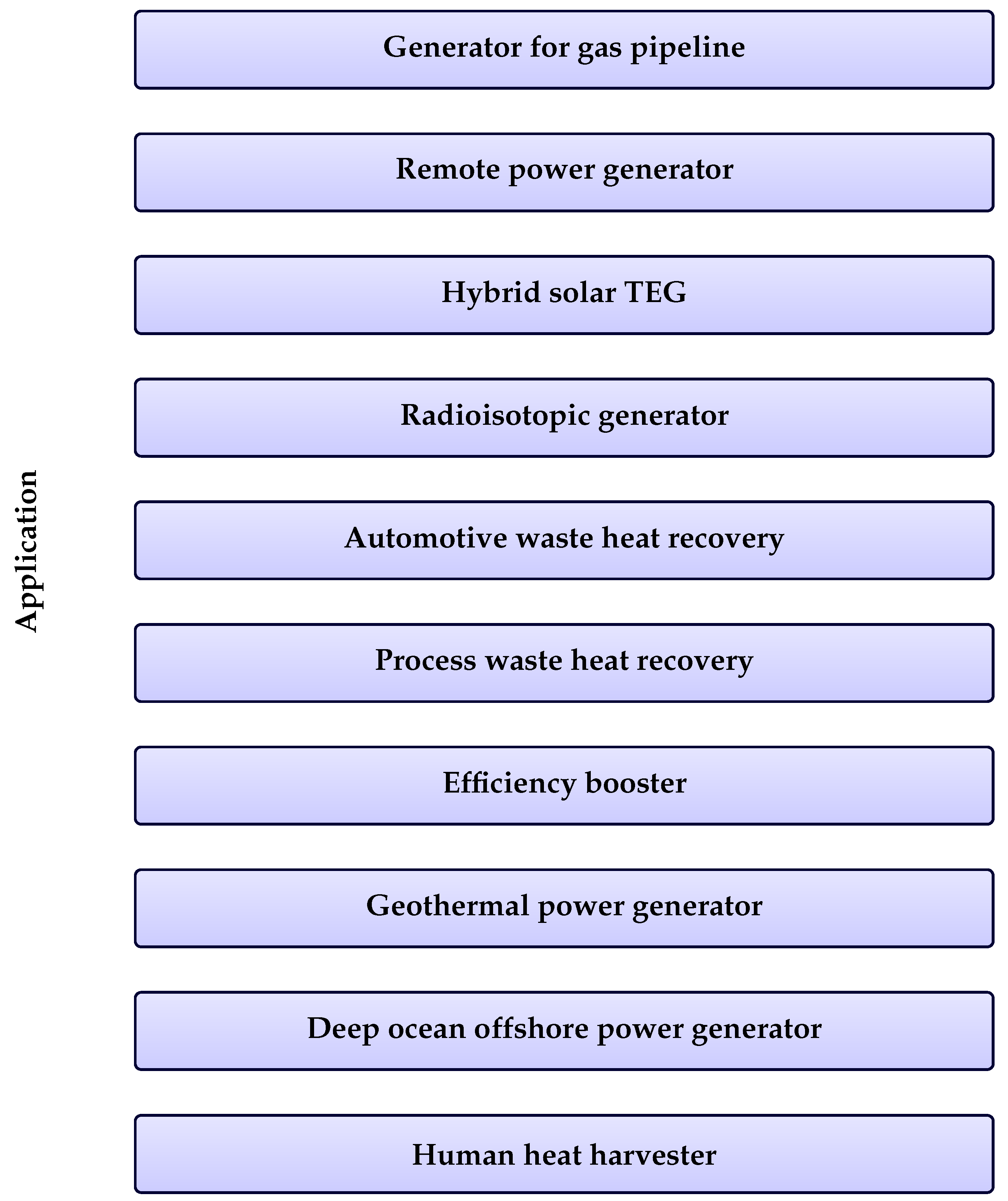
The thermoelectric power generator is used to produce power at low capacity. The ease of use makes it suitable for pipelines. It is used in remote and unmanned sites. The unavailability of solar radiation makes it superior to solar photovoltaic (PV) systems. Nowadays, hybrid solar systems encourage using thermoelectric systems with PV modules. TEG acts as the backup power source in this system. Many space rovers and missions are conducted with the help of radioisotope generators. The most common applications are waste heat recovery from automobiles [
29] and process heat recovery in factories, households, and electronic equipment [
30]. The low-frequency heat of a solar system, which is not utilized by solar cells, can be used by thermoelectric devices in tandem with solar cells [
31]. It acts like an efficiency booster. Integrating solar cells and thermoelectrics as a hybrid system has become a frequent application [
32]. Thermoelectric systems also have excellent potential to harness geothermal and deep ocean power generation. Several small-scale TEG devices have been reported previously to harness rejected human body heat. A schematic diagram highlighting the broad spectrum of applications of the thermoelectric generation system is depicted in
Figure 1.
1.2. Motivation, Objectives, and Contributions of This Study
Thermoelectric generators (TEGs) have emerged as a viable solid-state technology for producing electricity from low-grade thermal energy due to the increased focus on waste heat recovery and sustainable energy on a worldwide scale. The transition of TEG systems from laboratory demonstrations to widespread industrial deployment is hampered by a number of important obstacles, including low conversion efficiency, high thermal losses, interfacial resistances, and limited long-term durability, despite substantial research efforts. There is still a lack of a cohesive, methodical framework that combines thermal resistance analysis with performance metrics and next-generation material strategies, despite the fact that many studies have examined specific elements like heat exchanger designs, thermoelectric materials, and system integration. This review is motivated by the necessity of critically synthesizing the results from 135 papers, identifying enduring thermodynamic issues, and offering workable solutions for real-world applications in waste heat recovery.
The main goal is to provide a thorough analysis of thermoelectric generator technologies with an emphasis on thermodynamic performance assessment and improvement techniques. Particular goals consist of: (1) rigorously evaluating the effects of various heat exchanger configurations—plate, finned, and liquid-based—on system-level performance; (2) creating a single framework for evaluating TEG performance that combines the innovative Temperature Gradient Coefficient (TGC) with a comprehensive thermal resistance network model; (3) examining thermodynamic problems such parasitic losses, small temperature gradients, Carnot restrictions, and cyclic degradation; (4) offering an outlook for next-generation materials (flexible devices, liquid metal-enhanced, and thermoelectric ionic) and tailored suggestions for bridging the gap between present capabilities and commercial practicality.
This review advances the field in a number of significant ways. First, it presents a unified framework for evaluating thermodynamic performance (thermal resistance network + TGC), which makes it possible to compare various TEG designs quantitatively. Second, it includes a special chapter on “Thermodynamic Challenges and Countermeasures”, which provides a methodical examination along with workable solutions backed by summary tables. Third, it proposes standardized experimental methodologies while highlighting important gaps in the research, especially the lack of long-term stability and deterioration data. Lastly, the extended
Section 6 offers industrial application guidance, priority research areas, and precise numerical benchmarks (e.g., efficiency of 4–12% for standalone systems and TRL assessments). When taken as a whole, these contributions provide academics and practitioners with a clear road map for developing TEG technology toward scalable, dependable, and affordable applications in sustainable energy systems.
1.3. Research Methods
A methodical strategy is necessary for systematic reviews in order to guarantee scientific rigor, reproducibility, and transparency. In this work, we reviewed thermoelectric generator (TEG) technologies using a mixed quantitative and qualitative methodology according to PRISMA standards when appropriate. This approach is used to offer an unbiased summary of the quickly growing volume of literature. The qualitative component consisted of a thorough content analysis of a few chosen studies with an emphasis on material developments, system-level difficulties, heat exchanger designs, thermodynamic performance, and thermal resistance modeling. Combining these methods allows for a critical synthesis of technological solutions, performance indicators, and remaining gaps, as well as a comprehensive mapping of the research landscape.
Three primary steps comprised the review process: (1) planning the review; (2) collecting and selecting articles; (3) reporting and analysis. The main objective of defining the research scope during the planning stage was to assess the thermodynamic features of TEG systems. The following keywords were chosen, along with pertinent synonyms and combinations: “thermoelectric generator”, “TEG”, “waste heat recovery”, “thermal resistance network”, “heat exchanger”, and “thermoelectric materials”. We chose Scopus as the primary database because it covers a wide range of peer-reviewed engineering and energy-related literature. The search was limited to English-language journal papers published till 2025 during the collection and selection phase. Following a preliminary broad search, titles, abstracts, and complete texts were screened using predetermined inclusion/exclusion criteria, and duplicates are eliminated. A total of 344 records/papers were identified through database searching (primarily Scopus). Following the elimination of 52 duplicates, 292 items were filtered using abstracts and titles. Moreover, 87 of these records were eliminated for a variety of reasons, such as review articles being outside of the specified topic, not relevant to thermoelectric systems, or not focused on thermal features or heat exchangers. The remaining 205 papers underwent full-text evaluation, which led to the elimination of 67 more studies that did not fit the inclusion criteria. As a result, the qualitative synthesis ultimately contained 138 studies.
The methodical workflow, which shows the dataset’s gradual refining, is shown in
Figure 2. Only research that directly addressed TEG performance, thermal management techniques, and related thermodynamic factors was included.
2. Experimental Studies on Thermoelectric Generation System
This section presents the experimental methodologies needed to design a thermoelectric generation system. The impact of different process, geometric, thermal, and mechanical parameters on TEG system performance is discussed in detail.
2.1. Classification Based on the Arrangement of a Heat Exchanger and Heat Source
The design of TEG systems depends heavily on the heat exchanger arrangement and integration of the heat source. Based on existing literature, two primary configurations are considered: individual and combined arrangements. These two arrangements differ in design complexity, heat transfer arrangement, and process parameters.
2.1.1. Individual Arrangement
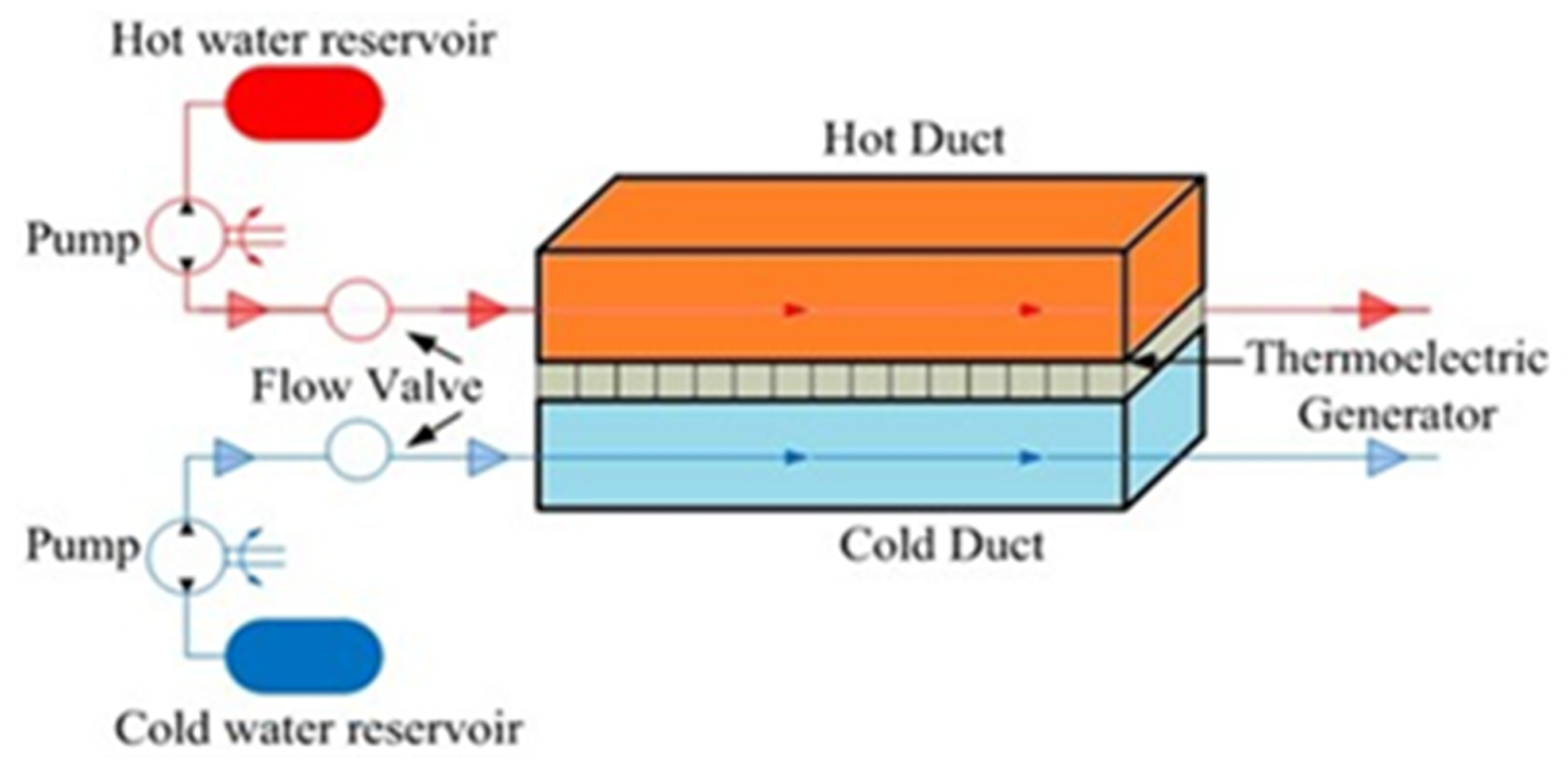
The individual system is the system that solely aims to produce power from heat. It takes directly available heat. It uses the waste heat produced in industry, automobiles, households, processes, and other equipment. Here, TEG systems receive heat by direct contact or through fluid circulation. Many research articles have been found to deal with this arrangement. Most researchers have conducted their experiments in two popular fluid flow modes: parallel and counterflow in the individual arrangement. The contributions of some of these research studies based on liquid circulation-based TEG systems and their outcomes are discussed in the upcoming lines. Rana et al. [
33] have experimented with a sandwich TEG system and parallel flow configuration utilizing a low-temperature heat source, as shown in
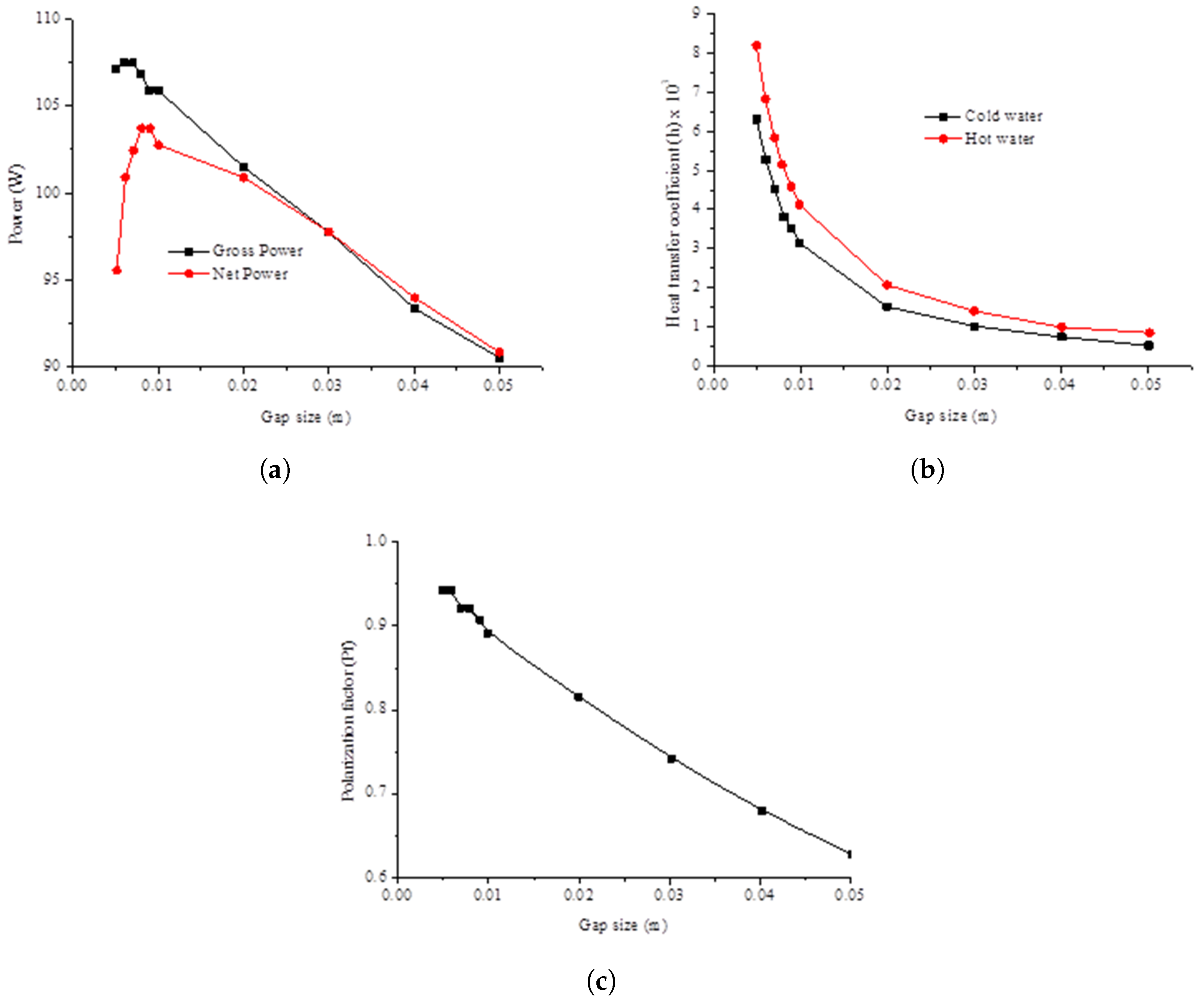
Figure 3. Here, the low-temperature heat source refers to a heat source possessing a temperature generally below 200 °C. They considered key parameters influencing thermoelectric generation such as the number of installed TEGs, heat input rate, length and width of a duct, rate of cooling, size of a gap, and parasitic loss. In this work, most of the parameters considered are evident except for the gap size, polarization factor, and parasitic loss, which must be defined (
Figure 4c). Gap size is the gap between the hot and cold ducts. They found a smaller gap size suitable for enhanced heat transfer, yielding a higher heat transfer coefficient, as shown in
Figure 4a. Parasitic losses occur in devices that take energy from the engine or device to increase ability or create more energy.
They found that the parasitic power loss increases if the gap size is reduced, as shown in
Figure 4a, leading to decreased net power for parallel flow configuration. As the gap length increases, the power drops significantly.
They defined a new factor called the polarization factor (
) as the ratio of temperature variation among hot/cold plates to temperature variation among hot/cold fluids. This polarization factor is similar to effectiveness as defined in the case of plate-type heat exchangers. They concluded that the decrement in the gap size increases the polarization factor due to subsequent enhancement in the heat transfer coefficient and decrement in convection thermal resistance, as shown in
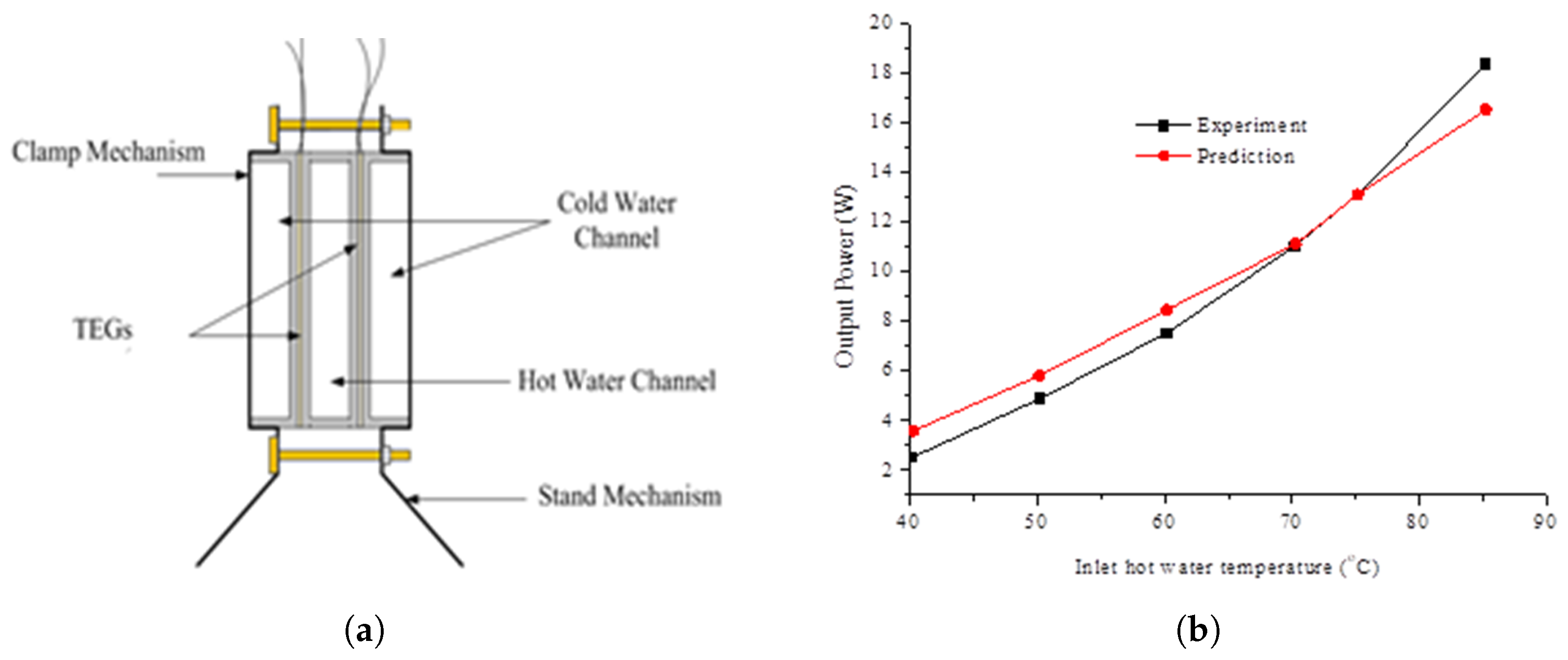
Figure 4b,c. Faraji and Akbarzadeh [
34] have studied symbiotic thermoelectric systems, as shown in
Figure 5a. The heat exchanger design is called Efficient Liquid-based Electricity Generation Apparatus Inside Thermoelectrics (ELEGANT). It includes four thermoelectric modules located between three rectangular passages for cold and hot liquids. This type of arrangement is more suitable than the two-fold sandwich passage. As reported in previous research, there is zero heat loss to the surroundings. However, convection losses cannot be avoided entirely in a thermoelectric system. The experiment is performed in a counterflow configuration. They considered inlet water temperature as a variable influencing the performance of this TEG system. The low thermal efficiency of thermoelectric generation can be avoided by simultaneously getting hot water under a symbiotic system. During their analysis, cold water temperature is held constant, and the predicted power curve obtained from the simulation is compared with the experimental curve, as depicted in
Figure 5b. It is realized that convection losses cannot be avoided entirely, which is not considered in the simulation, and the reuse of cold-side water temperature for preheating is conceptualized. The heat exchanger (HE)-TEG system is developed in line with the thermoelectric generator, as illustrated in
Figure 6a, and has been used by Wang et al. [
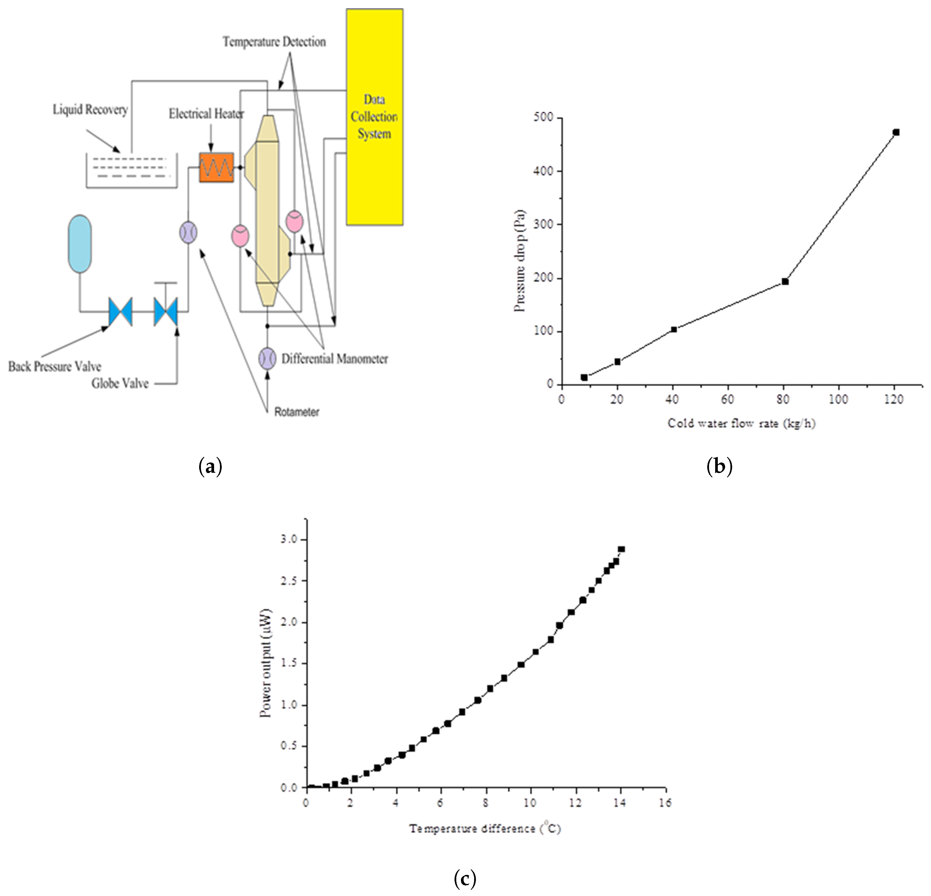
35] in their study. The heat exchanger was a multi-layered compact metal plate heat exchanger filled with foam. The heated air is used as a waste heat source for their system, and cold water is used as a cooling medium in another section of the heat exchanger.
This work approximates the flow as counterflow, and the back pressure is limited to 0.2 MPa. The performance of the heat exchanger is defined in terms of the ratio of real heat supplied to cold equipment to the heat flux available from heated air. They found that pressure drop increases with the mass flow rate, as shown in
Figure 5b. So, it is advisable that in the design stage, the heat exchanger surface strength should be ascertained so that heat exchanger bursting can be avoided. The high flow rate requires a higher strength of the plate and joints embodied. As heating continues, the hot side temperature of the fluid and the temperature difference increase with time. Since power and voltage are directly related to temperature differences, power increases with an increase in temperature difference, as depicted in
Figure 6b. Niu et al. [
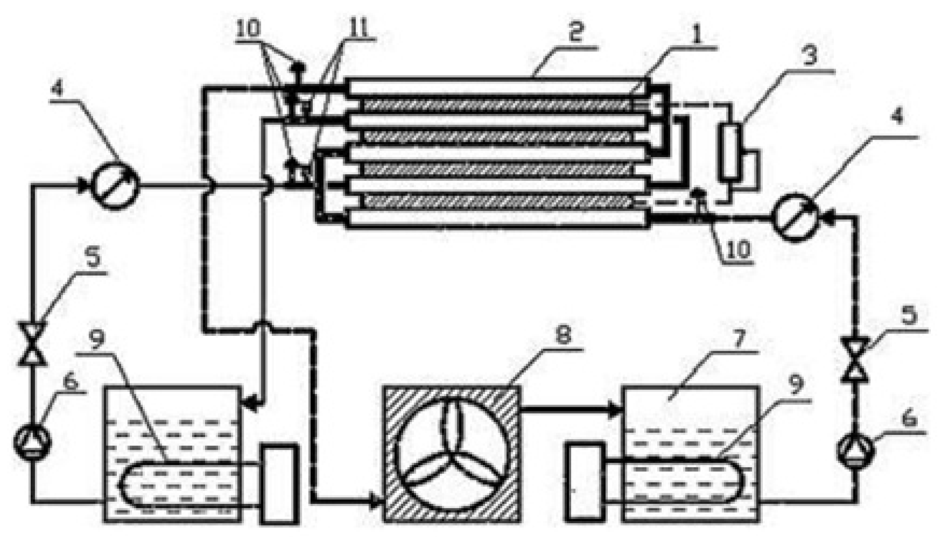
36] experimented with a sandwich thermoelectric generation system (as shown in
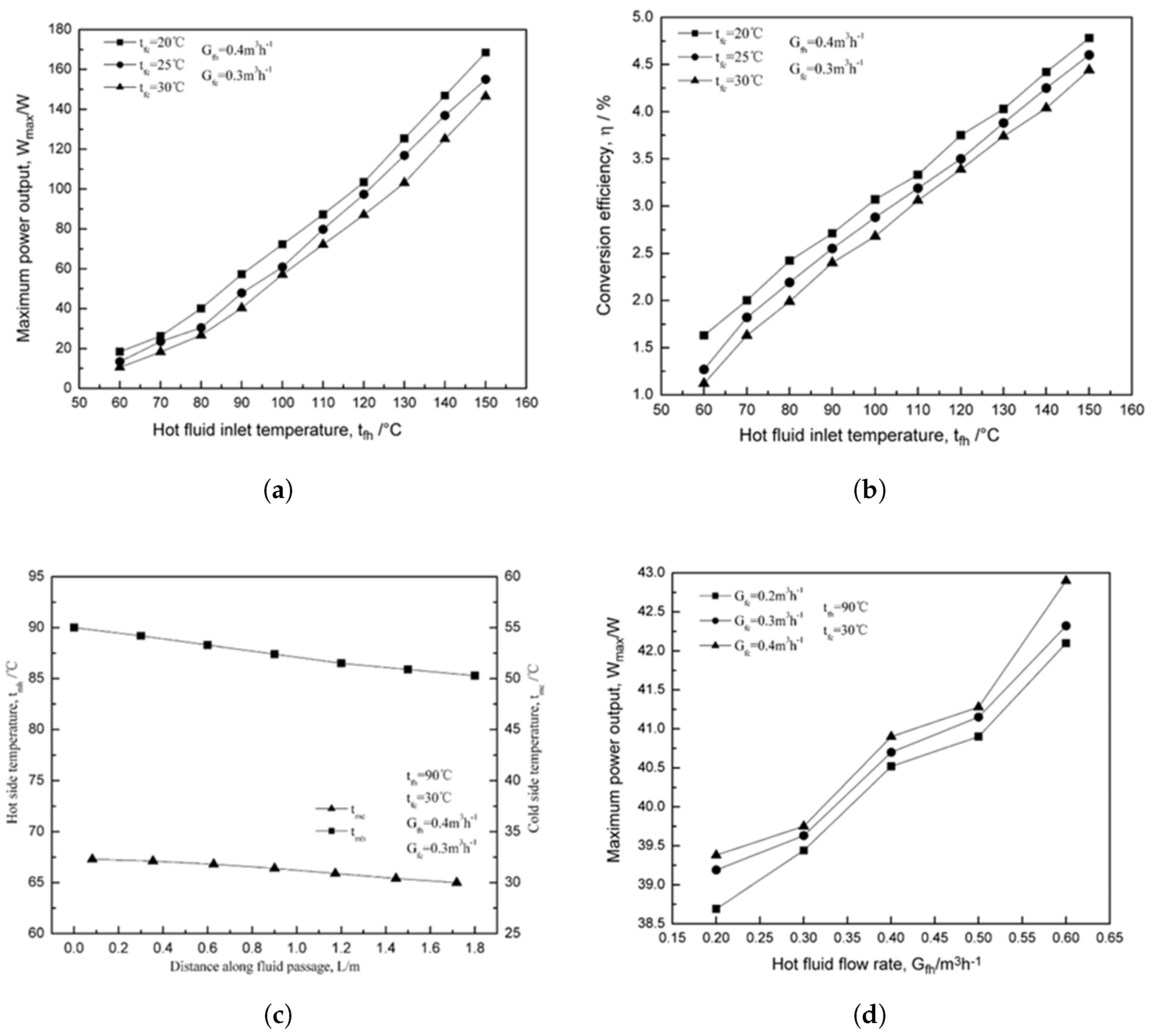
Figure 7) using a mixture of two fluids, i.e., glycol and water, in a mass ratio of 60:40 to harness the thermal energy. The study employed a temperature controller to control the temperature of both hot and cold fluids. The heat exchanger employed is multi-layered and parallel, with a counterflow configuration. The critical parameters considered during the experiment are fluid inlet temperature (hot), mass flow rate, and distance along the passage. Based on the results, they examined the maximum power output and conversion efficiency as affected by the operational conditions of the parameters. Efficiency and power can be increased by two means. Maintaining a higher temperature on the hot side and a lower temperature on the cold side is always recommended to obtain a greater temperature difference. The inlet temperature and flow rate of hot fluid have a unique role, as depicted in
Figure 8a,b. The uniform temperature difference along the flow passage is obtained in the case of counterflow. The temperature distribution of hot and cold duct temperatures in counterflow is plotted in
Figure 8c. The cumulative effect of temperature differences along the flow passage is responsible for higher power generation. With the increase in the flow rate of hot fluid, the output power increases, as presented in
Figure 8d. They also emphasized the need to optimize heat exchanger geometry and will apply it in future work. In this work, the heat loss with insulation was found to be ≤3.5%. The maximum combined uncertainty in the conversion efficiency was estimated to be ±6.7%, based on the instrument accuracies of pressure (±0.5%), voltage/resistance (±0.2%), and power (±0.5%), using the root-sum-square (RSS) error propagation method. No replicate measurements were available; therefore, a statistical analysis of measurement variability could not be performed.
Kumar et al. [
37] have developed a sandwich plate-type heat exchanger for power generation for low-temperature applications. Water is circulated in a closed loop in two configurations: parallel flow and counterflow configuration. Counterflow has better performance in terms of voltage and efficiency. Less heat is required to supply the modules. They found that a uniform temperature profile is obtained in the counterflow, which is responsible for enhanced power and efficiency along the flow direction. If the mass flow rate is varied during experiments, then maximum power is obtained at the optimum flow rate. Favarel et al. [
38] studied the optimized placement of thermoelectric modules in sandwich TEG hot and cold heat exchangers. Three configurations are considered, i.e., a fully covered heat exchanger with TEG, with all the modules on the same side, half on the right, and the remaining on the left. The latter two configurations are better than a fully covered heat exchanger arrangement. This experiment indicates that the heat exchange surface should not be fully covered. The intense penetration requires some gap from the left or right side of the surface. Boonyasri et al. [
39] have designed a thermoelectric generation system using evaporative cooling to assess thermal performance. The counterflow configuration maintains uniform temperature differences across the flow direction, while parallel flow has decreasing temperature differences. Counterflow configurations perform better in terms of power generation and efficiency. Suzuki et al. [
40] have experimented with TEG with different fluids in hot and cold channels. This work focuses on the optimum system design of TEG systems. Maximum power developed depends upon thermo-physical properties of thermoelectric material and fluid, heat transfer, and panel dimensions. They propose different types of designs that save material and space. Chen et al. [
41] have used a plate-type thermoelectric system in both parallel and counter configurations for experimental purposes. They found that using insulation decreases the heat loss by 5%. If modules are connected in series, they generate greater voltage than in parallel combinations. Parallel flow configuration leads to more thermal consumption and less output power. Lesage and Pagé-Potvin [
42] have investigated the performance of liquid-to-liquid power generation systems. In this work, the power output has an exponential relation with temperature and a square root function in connection with fluid flow under variable thermal conditions. Kumar et al. [
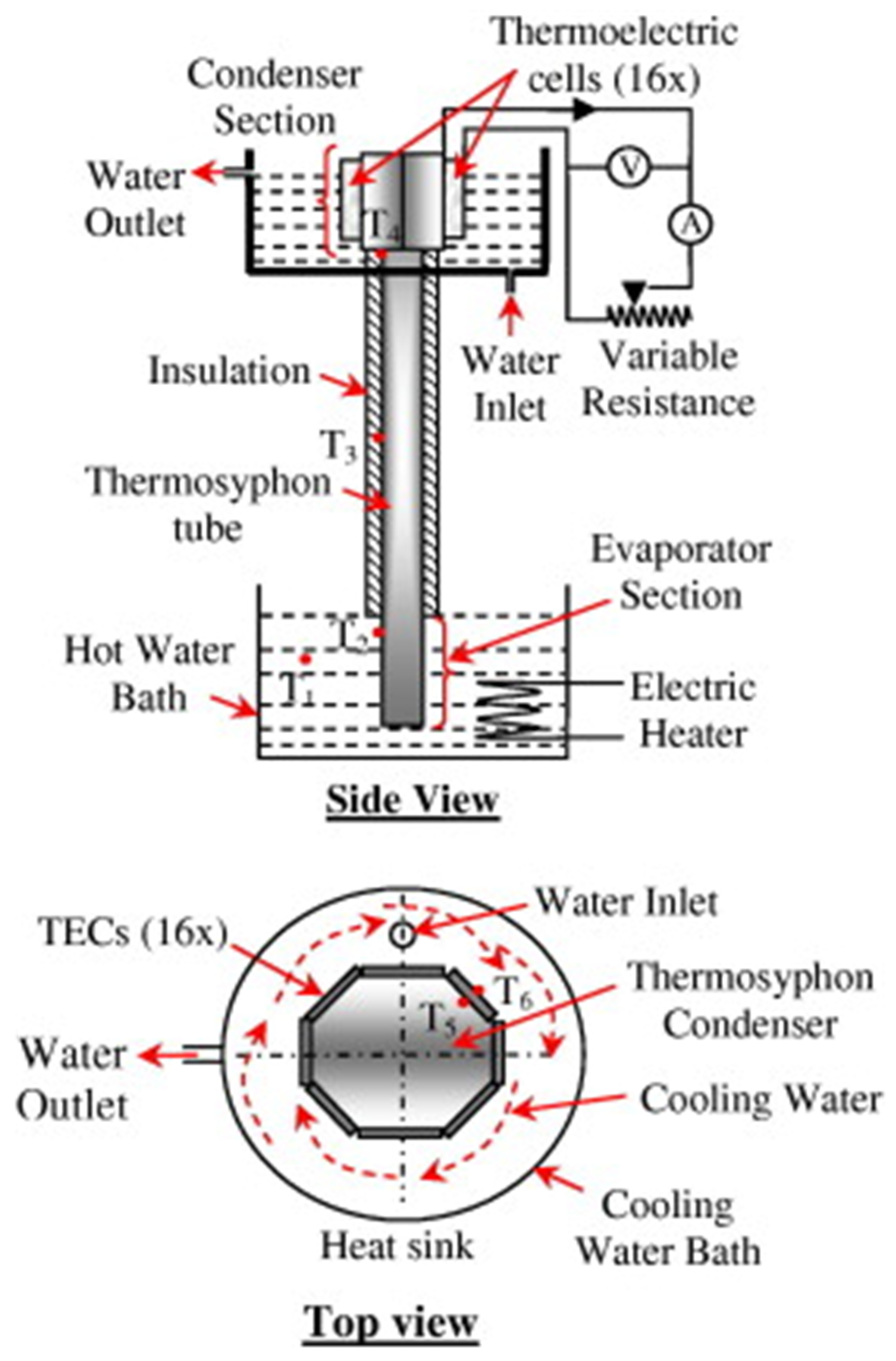
43] studied thermos-siphon integrated thermoelectric generators, and parametric optimization was conducted using the response surface methodology. The thermosyphon consists of an evaporator and a condenser connected by a pipe. The evaporator is maintained at vacuum pressure. Parametric optimization is done using a Box–Behnken design (BBD), with the benefit of fewer experiments that need to be performed. They defined new thermal parameters called filling ratio and found they contributed insignificantly to performance. The system efficiency depends on vacuum pressure and evaporator temperature. The optimum operating condition is decided based on the relative change in evaporation rate.
Another popular scenario is direct heating instead of circulating fluid. A few research works based on direct heating in TEG systems are discussed in the upcoming lines. Hsu et al. [
44] have tested the feasibility of an exhaust pipe automobile TEG system. Their finding indicates that open-circuit voltage possesses a linear relation with temperature difference and that power output increases with temperature difference. Trashkeev and Kudryavtsev [
45] experimented on thermal energy recovery in thermoelectric systems. Their investigation indicates that there is a temperature and voltage drop along the direction of exhaust flow. Liu et al. [
46] have experimented on the automotive plate-shaped heat exchanger of the TEG with a catalytic converter (CC) and muffler. The focus of the study is thermal uniformity and pressure drop characteristics. Pressure drops across the muff, and the catalytic converter and heat exchanger are low. Three installation positions of the thermoelectric generator are checked. This position is mainly between the muff, catalytic converter, and heat exchanger segments. If the TEG lies between the muff and CC, it gives higher efficiency. Martínez et al. [
47] have adopted a direct contact heat exchanger with a fin. The effect of pressure drop, fin length of the hot-side heat exchanger (HSHE), fin gap, and base thickness of the HSHE is checked. Low thermal resistances lead to high electric power but also account for high-pressure drops. A high-pressure drop causes a decrease in power. Liu et al. [
48] experimented with a direct heat-to-electricity (DHE) apparatus. This experiment triggered and led to feasible harvesting for large-scale use. A total of ninety-six TEGs produced 500 W power output. The temperature difference for the production of this power is 200 °C. The efficiency obtained is 4.5% at a hot inlet temperature of 95 °C. It can also be observed that a high-temperature heat source is more economical for power generation than a low-temperature heat source. It is also evident that a substantial temperature difference leads to higher power and efficiency. Gou et al. [
49] have investigated a low-temperature thermoelectric generator dedicated to heat recovery. Both theoretical analysis and experimental evaluation are performed. Increasing the heat transfer area will enhance the cold-side heat transfer and ultimately improve performance. Besides these, based on the shape/nature of the heat exchanger employed, other types of individual arrangements of thermoelectric generators are discussed below in
Table 1.
As demonstrated by Niu et al. [
36], Kumar et al. [
37] and Boonyasri et al. [
39] studies on individual TEG arrangements generally show that counterflow configurations are superior to parallel flow in achieving more uniform temperature differences along the flow path, leading to higher power output and conversion efficiency. Direct-contact heating techniques (e.g., Liu et al. [
46], Liu et al. [
48], Martínez et al. [
47]) offer easier integration with exhaust streams but have more difficulties with thermal uniformity and pressure drops, whereas fluid-circulation-based systems (e.g., Rana et al. [
33], Faraji and Akbarzadeh [
34]) excel in controlled low-temperature waste heat recovery through parameters like gap size, polarization factor, and symbiotic hot-water reuse. Variations in heat exchanger design, insulation quality, and treatment of convection/parasitic losses, which are occasionally idealized in simulations, are frequently the cause of claimed performance discrepancies. Large-scale economic viability, long-term durability under actual industrial settings, and systematic geometry optimization are still important research gaps that highlight the need for hybrid designs that strike a compromise between improving heat transmission and minimizing system complexity.
2.1.2. Combined System
If the thermoelectric system is used for a purpose other than waste heat recovery or with an extra arrangement, then it can be called a combined system. Nowadays, it is preferred to use a thermoelectric system as a subsidiary cogeneration system to improve the efficiency of others. Kim et al. [
55] performed an experimental performance analysis on an Automobile Exhaust heat pipe-based heat exchanger (HPTEG). It is well known that temperature difference affects voltage and power. The heat transfer area is increased by incorporating a heat pipe. Using a heat pipe, more TEG can be accommodated, and significant power can be produced even at low temperatures. Remeli et al. [
20] have developed a Combined Heat Pipe Thermoelectric Generator (CHP-TEG). They designed a small prototype of the test setup in order to study heat transfer and its effectiveness. The research employed a TEG heat exchanger under counterflow conditions, and air is circulated in the fluid loop of the heat exchanger. A comparison between theoretical and experimental results is made, and it is found that the analytical model underestimated the heat transfer rate in contrast to the test data. The effectiveness showed an upward trend due to subsequent enhancement in air velocity in the cold duct. Date et al. [
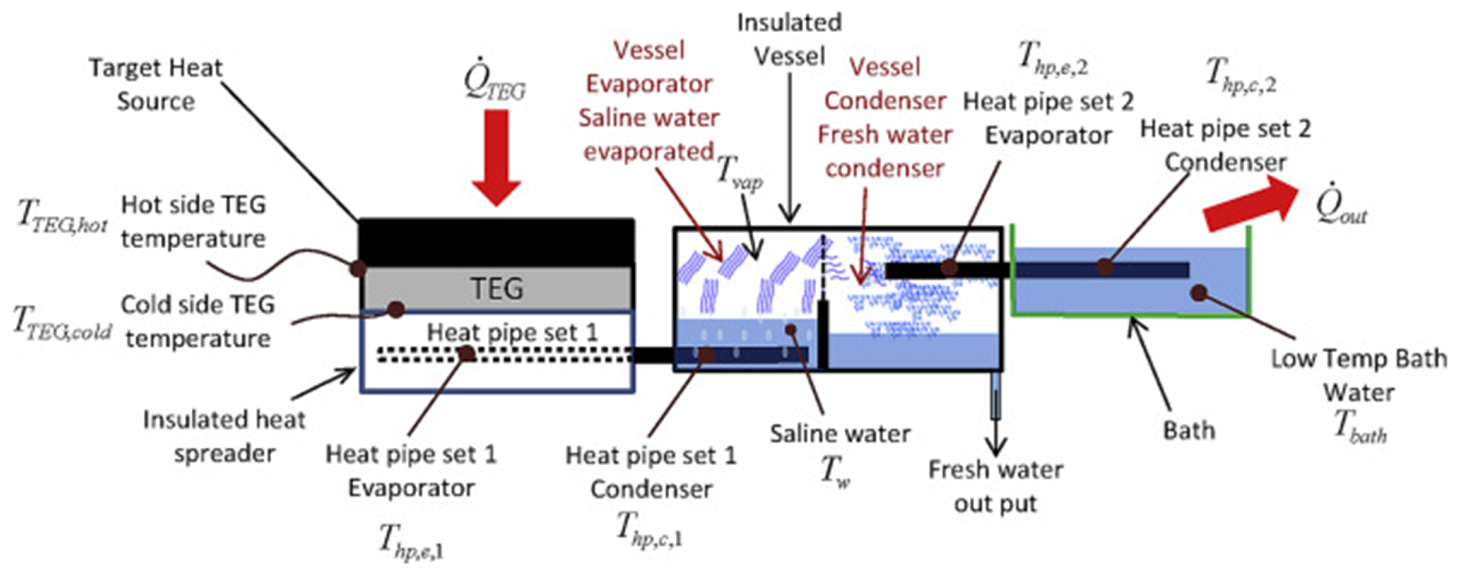
56] conducted an experimental study on a combined TEG-water desalination system, as shown in
Figure 9. They studied the variation of various factors such as open-circuit voltage, hot plate temperature, the temperature of the cold plate, theoretical water temperature, absolute vapor pressure, sensible and latent heat, mass flow rate, and heat supplied. The water desalination module utilizes low-temperature heat from the cold side of the combined system. Here, heat flux with low saturation temperatures is supplied to this TEG-desalination system with less heat loss. He et al. [
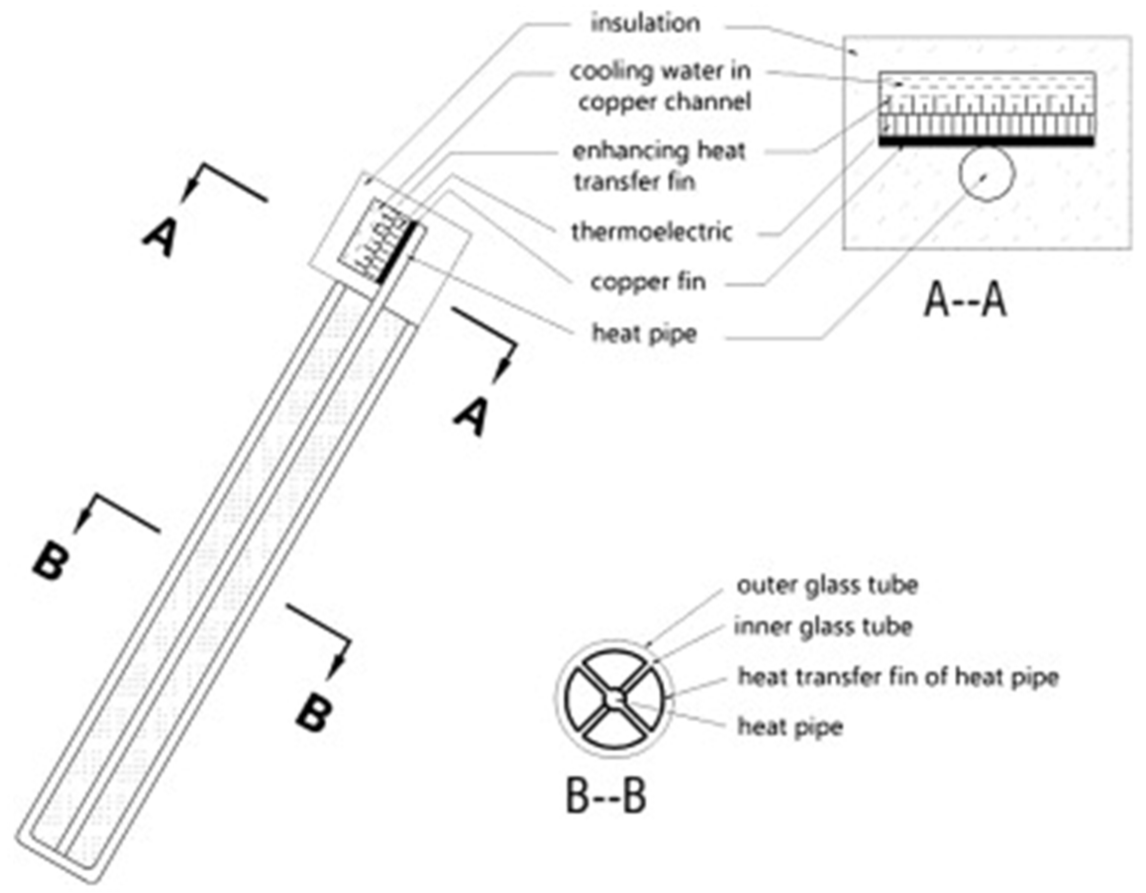
57] utilize the solar heat pipe-thermoelectric module (SHP-TEG), as depicted in
Figure 10, for low-temperature heating and electricity generation. In this work, a parametric study is conducted to showcase the effect of solar irradiation, thermoelement length, number of thermoelements, cross-sectional area, and cooling water temperature on the power developed and thermoelectric conversion efficiency. Results suggest that the system has a thermal efficiency of about 55% and an electrical efficiency of above 1%. Dai et al. [
58] have developed a model to evaluate heat flux through solar radiation, which is passively cooled by a pipe dipped in an acrylic water tank kept at a certain distance. The immersed liquid cooling system obtains a high heat transfer rate. They examined the rate of heat loss via a water storage tank in the environment. They observed that fewer TEGs accompanied by a higher concentration ratio result in maximum variation in the temperature. The power developed decreases as the quantity of TEGs increases, which finally leads to minor variations in temperature. Singh et al. [
59] have experimented with a thermosyphon thermoelectric generation system (TTG) based on the solar pond, as illustrated in
Figure 9. The hot side of the thermoelectric module is heated through the bottom layer of the solar pond and cools the cold plate via the upper water layer of the solar pond (
Figure 11). The combined solar pond–thermoelectric generation system exhibits a temperature difference of 27 °C, an open-circuit voltage of 26 V, and a short-circuit current of 0.4 A. Since the proposed system generates power in the watt range, it is suitable for low-power-consuming devices.
A few combined TEG systems are discussed below in
Table 2. Their results give direction toward the progressive research carried out in thermoelectric generation.
It is important to clarify that different efficiency metrics are available in the literature. The percentage of heat input across the thermoelectric generator that is transformed into electrical power is known as the thermoelectric conversion efficiency, and it is usually between 1 and 3.35%. On the other hand, the hybrid solar heat pipe system’s thermal efficiency (~55%) indicates how effectively heat is collected and transferred to the thermoelectric module, whereas the overall electrical efficiency takes into consideration the combined effectiveness of the solar thermal collector and the thermoelectric conversion process.
The combined TEG systems show versatile integration potential beyond standalone waste heat recovery, especially through the incorporation of thermosyphon and heat pipe that increase heat transfer area and allow cogeneration applications such as seen in solar pond (Singh et al. [
59]) and desalination (Kim et al. [
55]). In comparison to passive cooling techniques, counterflow designs and heat pipe integration (Date et al. [
56], Remeli et al. [
20]) typically produce higher efficacy and power output, while solar-driven systems (He et al. [
57], Dai et al. [
58]) achieve respectable thermal efficiencies (55%) but are still constrained by sensitivity to the number of TEG modules and low electrical efficiency (<2%). Idealized boundary conditions, unexplained convective losses, and different cooling strategies are the main causes of conflicting data, such as analytical models underestimating heat transfer rates (Remeli et al. [
20]) or power decreasing with more TEGs (Dai et al. [
58]). Long-term system durability, economic scalability for practical cogeneration, and optimization of hybrid arrangements that concurrently enhance thermal and electrical outputs while minimizing parasitic losses are still major research necessities.
2.2. Classification Based on the Working Fluid Used
The choice of working fluid plays a crucial role in the TEG systems. They influence the heat transfer efficiency and power generation attributes. Different fluids possess different physical properties (i.e., conductivities and capacities) and stability under different operating conditions. Here, two subsections are formed to categorize the working fluid as an ordinary fluid and a nanofluid. The subsequent subsections will discuss them in detail.
2.2.1. Ordinary Fluid/Chemicals-Based TEG System
A thermoelectric system mainly consists of two circuits. The hot circuit comprises hot fluid and is meant for heating. The cold circuit is similar to the hot circuit but designed for cooling. Most of the research work utilizes the same fluid for both circuits, and very few use different fluids. Based on the literature studies, it is found that water is the most common fluid used for circulation [
34,
56,
57,
70]. Water has the advantage that it is easily available and exists in abundance. However, the source of obtained water can be different. Dai et al. [
58] have devised a TEG system employing liquid metal. They obtained experimental results for both high and low-volume flow rates in which the hot plate is heated by liquid metal and the cold plate is cooled by water. They noticed that this arrangement produces large temperature differences, which lead to greater output voltage. The difference in temperature between the waste heat source and liquid metal heating plates has also been considered a variable by them, and it influences the overall working of the TEG system. They also observed that the conductivity of the heating plate does not enhance the system’s efficiency. Water from geothermal sources can become a viable option for thermoelectric generation. Geothermal energy is received via naturally occurring hot showers and underground sources of water [
69]. Geothermal energy-based TEG systems can balance local and regional demand [
71,
72,
73]. The low-temperature geothermal heat source can be harvested with the help of the Kalian cycle [
74]. Apart from water, liquid metal [
58], air [
20,
35], and a mixture of glycol and water [
36] are frequently used.
2.2.2. Nanofluid-Based TEG System
Nanofluid is a colloidal nanoparticle solution smaller than 100 nm within the base fluid. The base fluid may be water, alcohol, oil, lubricant, or other common fluid. The nanoparticle material comes from the group of metals, oxides, ceramics, and carbon in various forms [
75]. Nanofluid has better thermo-physical properties [
76,
77,
78,
79,
80,
81,
82,
83], mass diffusivity [
84], and heat transfer features than other general fluids [
85]. The heat transfer capability of nanofluid depends upon the thermal conductivity. The thermal conductivity of nanofluid depends upon the aspect ratio, the shape of the nanoparticle, the volume/weight fraction, and the shape of the nanomaterial [
86]. Some researchers reported that nanofluid viscosity depends on temperature and particle volume fraction [
87]. The nature of the flow of nanofluid has a considerable impact on power generation. Laminar flow is more beneficial as compared to turbulent flow. Turbulent flow is only fruitful if it enhances thermal conductivity and minor improvement in viscosity [
88].
Although nanofluids provide significant improvements over traditional fluids in terms of thermal conductivity, heat transfer coefficient, and total power output, there are a number of significant obstacles to their practical application in thermoelectric generator (TEG) systems. Key limitations include sedimentation and aggregation of nanoparticles, which compromise long-term stability and may result in decreased performance during prolonged operation. Furthermore, the higher pumping power needed due to the increased viscosity of nanofluids could reverse some of the thermal advantages and increase total energy usage. Other concerns involve higher synthesis and preparation costs, as well as increased corrosion and fouling risks as a result of nanoparticle interactions with system components. These aspects have a major impact on the scalability, long-term dependability, and techno-economic viability of nanofluid-based TEG systems. Therefore, careful examination of these trade-offs in addition to the reported performance improvements is necessary for a fair assessment.
Li et al. [
89] have evaluated the functioning of nanofluid-cooled TEG systems for automotive waste heat recovery. They compare the performance of Cu-Ethylene glycol (Cu-EG) nanofluid coolant with ethylene glycol–water (EG-W) coolant for the same mass flow rate, and it is noted that Cu-EG nanofluid has better performance. The concentration of nanofluid is varied from 1% to 6% in this study. It is found that Cu-EG nanofluid can reach a lower cold plate temperature, and a greater power output in a thermoelectric generation system for the same mass flow rate is obtained. It was found that the total optimal area decreased in the case of Cu-EG nanofluid, and the power output increased significantly compared to the EG-W coolant. It happens because of an increase in the thermoelectric system’s hot-side heat transfer coefficient. The power developed, and the conversion efficiency increased with the increment in nanoparticle concentration.
Wu et al. [
90] have claimed that they employed nanofluid as a cooling agent in a hybrid PVT-TEG system. The hybrid PV–TEG system’s performance assessment was evaluated under and without glazing. The three-step conversion process is indicated in their research article. Firstly, electricity is generated by the photoelectric effect after the heat rejected by the photovoltaic module is absorbed by TE modules, and at last, the rejected heat from the TE module is carried away by nanofluid. The nanofluid consisted of Cu/water flowing through the parallel copper pipes. This arrangement acts as a cooling medium in their study, and they observed that cooling fluids such as the nanofluid have better system efficiency than water. Further, a comparison between the ordinary fluid and nanofluid-based TEG system is listed in
Table 3.
3. Numerical Studies on Thermoelectric Generation System
It is seen that the majority of the numerical and experimental studies are conducted simultaneously. The numerical study is separated from the experimental part for the reader’s convenience. Hence, this section deals with the contributions of numerical analysis or simulations in thermoelectric generation systems. Some commercial software, such as FLUENT, ABACUS, COMSOL Multiphysics, etc, are used to conduct simulation studies. These tools are utilized to simulate physical phenomena across engineering and scientific disciplines. They use numerical methods to solve partial differential equations by discretizing the larger domain into smaller elements. These tools predominantly use the Finite element/Finite volume method to approximate the solution within the elements [
98]. They are designed for seamless Multiphysics integration, allowing thermo-electric coupling and offering various implicit/explicit solvers.
Suzuki [
70] has investigated the 2D movement of both fluid and heat within twin working fluids, ultimately leading to the investigation of 2D temperature variation within the fluid and solid simultaneously. The flow configurations considered are parallel, counter, and split, respectively. FLUENT 95 software is used to determine the fluid velocity profile and temperature profile in the proposed configurations. The EMF is calculated to show the stagnation point in counterflow and split flow configurations. They identified that the material’s thermal properties do not impact the EMF value. The velocity linked with the thermal fluid has a role in generating power. It is noted that an increase in velocity results in an increase in generated power. In consultation with numerical results, it is observed that higher values of emf are acceptable only under the configurations of counterflow, in contrast to parallel flow, which also occurs when the velocity is slow. The EMF in parallel flow is found to have a slightly higher value than counterflow due to the temperature reliance associated with TE elements, fluids, and electrode materials. In addition, heat transfer coefficients may behave in a complicated manner.
Suter et al. [
99] have studied the 1D conduction heat transfer model of geothermal parallel-plate heat exchangers. Thermal parameters such as geometric parameters, maximum efficiency, and minimum size are considered. A computational fluid dynamics (CFD) model consisting of 4 leg modules, radiative and convective heat transfer, is considered. The maximum hot side and minimum cold temperatures recorded are 413 K and 293 K, respectively. The length of the leg considered in the simulation is 4mm. Regarding the uncertainties in radiative heat transfer, calculations are performed using the Monte Carlo method. Admasu et al. [
100] have developed a thermal–electrical multi-coupled heat exchanger model. A finite element-based model, with and without uniform temperature distribution, is used in the formulation. The effects of uniform and non-uniform temperature distributions on thermoelectric generation system output power have been studied. Astrain et al. [
101] have conducted a computational study on the heat exchanger resistance of a non-isolated prototype receiving heat from a boiler. The study reveals that 1 kW of electric energy per meter of chimney height can be produced. The difference between the obtained experimental and theoretical power output is less than 5%. Baskaya et al. [
102] have conducted a numerical study on the optimum place of a TEG in a heat cell in a TEG with a condensing combi boiler. The maximum temperatures on the upper and lower sides of the heat cell are 350 °C and 80 °C, respectively. However, they mentioned leakage on the hot side as a significant problem.
Borcuch et al. [
103] have done CFD modeling of the Gaseous hexagonal Hot-side heat exchanger (HHX), TEG, and Cold Heat exchanger (CHX). Three fin configurations are used in modeling: a mainly equal fin along the heat exchanger, a half-cut fin, and a full cut to the heat exchanger radius. Research determines the influence of the thermal, flow, and geometrical parameters on power generation. Primarily, uniform temperature differences do not generate the highest power and efficiency. Fisac et al. [
104] have conducted a numerical and feasibility study of solar photovoltaic thermoelectric hybrid systems. The temperature distribution beneath the solar cell while rejecting heat is the basis for electricity generation in TEG. A mathematical model shows the interaction between thermoelectric and photovoltaic technology. Högblom and Andersson [
105] have developed a three-dimensional FEM model to investigate the effect of contact resistance on the performance. In their analysis, it is concluded that the non-inclusion of contact resistance overestimates the power and efficiency. The non-inclusion of contact resistance leads to 200% higher electrical power and 50% higher heat flow. Huang et al. [
106] have simulated and tested a concentric cylindrical thermoelectric generator and annular thermoelectric module (ATEM). The performance of both generators is assessed and compared with the conventional module. A new term called heat transfer filling factor
f is introduced, characterizing space utilization. The results indicate the same open-circuit voltage as that of the conventional module. However, using a heat pipe system enhances radiation heat transfer and produces more power. Kossyvakis et al. [
107] have prepared a computational model under steady-state transfer. Performance prediction is necessary for material and design parameters that deal with the thermoelectric generators and systems. The obtained computational data is also compared with the manufacturer’s and experimental data. The convection heat loss is more dominant (11.6%) in the case of the heat loss model. The radiation losses account for only 5.1% of the power decrease.
We encounter various papers in the literature, some devoted to numerical studies and some dealing with experimental studies. In TEG system design, numerical and experimental studies offer unique strengths for understanding and optimizing system performance. There is a need to analyze the difference in results obtained from these studies. A comparison between the numerical and experimental results at identical field conditions is listed in
Table 4. It highlights key simulation findings and describes the difference/alignment between numerical and experimental results.
The significance of flow configuration is demonstrated by numerical studies on thermoelectric generation systems. Counterflow and optimized fin designs often outperform parallel arrangements in achieving uniform temperature distributions and higher power output, as demonstrated by [
70] and Suter et al. [
99]. However, there are contradictory results about temperature uniformity. Some models indicate that perfectly uniform temperature differences do not result in maximum efficiency, and the role of contact resistance, which Högblom and Andersson [
105] discovered, can cause power to be overestimated by up to 200% if ignored. These disparities are mostly caused by methodological differences, such as boundary condition simplifications, the exclusion of convection/radiation losses, and different degrees of multiphysics coupling. There are still significant research gaps in accurately simulating real-world parasitic losses, long-term contact deterioration, and hybrid system integration under transient settings, despite the fact that several studies claim good agreement between simulations and experiments (differences < 5% in Admasu et al. [
100]). Future numerical work should prioritize comprehensive uncertainty analysis and validation against large-scale experimental data to bridge these gaps.
We propose a unified framework for evaluating the performance of thermoelectric generators (TEGs) by combining the Temperature Gradient Coefficient (TGC) with the thermal resistance network model. This framework provides a systematic, quantitative, and comparable approach for assessing overall system performance across different heat exchanger types, operating conditions, and scales. The overall thermal resistance from the heat source to the heat sink can be represented by the total thermal resistance of a series–parallel thermal network as
where
,
,
,
,
,
, and
denote the hot-side convective resistance, cold-side convective resistance, hot-side heat-exchanger conductive resistance, cold-side heat-exchanger conductive resistance, hot-side contact resistance, cold-side contact resistance, and conductive resistance of the thermoelectric legs, respectively.
The heat flow through the TEG system is related by
where
and
are the temperatures of the source and sink, respectively.
We define the temperature gradient coefficient (TGC) to quantify the total available temperature difference at the thermoelectric module:
Here, and are the temperature differences across the leg and the overall temperature difference between the hot-side and cold-side inlet fluid, respectively. While lower values suggest considerable interface or heat exchanger inefficiencies, close to 1 indicates effective thermal management (minimum parasitic losses).
Using the unified framework, three key indicators, i.e., effective figure-of-merit, heat-exchanger effectiveness, and overall system efficiency, are redefined to reflect real coupled conditions. The effective figure-of-merit can be defined as
This represents the actual thermoelectric conversion capability under operational conditions by adding
to the usual
. Another coefficient, i.e., heat exchanger effectiveness (HX), can be defined as
where
U is the overall heat transfer coefficient of the heat exchanger,
A is the heat transfer area, and
is the minimum heat capacity rate.
The efficiency directly links electrical power output to actual heat extracted from the hot source, considering all parasitic thermal resistances:
where
is the electrical power generated and
is the heat supplied to the hot plate.
Within the framework of the unified thermal resistance network, contact, convective, and conductive resistances are assessed, demonstrating how boundary-layer growth affects the effective temperature gradient throughout the TEG modules.
Table 5 lists the different thermal resistances, convective heat transfer coefficients, boundary-layer characteristics, and overall performance metrics for plate, finned, and liquid-based heat exchangers. The baseline plate-type design is used to express relative overall thermal performance. This information is a useful guide for maximizing TEG system thermal management by illuminating the trade-offs between design simplicity and heat transfer efficiency. The values are typical ranges recorded under forced convection conditions that are pertinent to applications involving waste heat recovery. The application of the unified framework to a few TEG systems from the literature [
19,
40,
53,
70,
113,
114,
115] is shown in
Table 6, which indicates increased consistency in performance comparisons.
The advantages of this unified framework are that it enables direct comparison between different TEG configurations, allows bottleneck analysis, supports optimization by maximizing TGC, facilitates scaling analysis, and enables techno-economic analysis and implementation of scaled coupled simulation.
Table 5 shows an example that computes the different parameters involved in the unified framework from the chosen literature.
Besides predicting the numerical behavior of thermoelectric generation systems, several researchers in recent papers have conducted optimization studies of the performance of TEGs using different optimization algorithms and strategies. Among existing optimization techniques, artificial neural networks (ANN) and deep neural networks (DNN) are popular techniques used to determine thermoelectric generation system-optimized performance.
Table 7 lists studies based on optimizing TEG performance by machine learning methods.
4. Thermodynamic Challenges and Countermeasures
Although thermoelectric generators (TEGs) present a viable solid-state option for waste heat recovery, basic thermodynamic constraints prevent their widespread use. The main issues—low conversion efficiency due to low temperature gradients, high thermal losses, significant interfacial thermal resistances, Carnot efficiency constraints, and degradation under transient/cyclic operation—are methodically examined in this section. Here, expected countermeasures are suggested in addition to the thermodynamic challenge. Quantitative evaluation and optimization of these problems are made possible by integration with the previously suggested Temperature Gradient Coefficient (TGC) framework and unified thermal resistance network.
4.1. Intrinsic Low Temperature Differential
The intrinsic low temperature differential (generally less than 100 K in low-grade waste heat sources) across the thermoelectric legs is a fundamental drawback of TEGs, leading to modest power densities and conversion efficiencies that are usually less than 5–8%. Poor thermal coupling between the module and the heat source/sink is the cause of this. Advanced heat exchanger designs that increase the effective include plate, finned, and liquid-based countermeasures. Liquid-based systems can obtain TGC values of 0.75–0.92, which significantly improves the usable gradient. This is further amplified by nanofluid-enhanced heat transfer: through higher convective heat transfer coefficients, graphene-based nanofluids have been demonstrated to boost output power by up to 26% and conversion efficiency by about 15%.
4.2. Interfacial Thermal Resistances and Thermal Losses
System performance is greatly diminished by parasitic losses caused by convection/radiation at interfaces, high contact resistances, and conduction via structural components. These diminish TGC in the network model by increasing total thermal resistance (). Optimized network architectures for thermal resistance incorporating direct countermeasures include the use of thermal interface materials (TIMs) and reduced boundary layer effects. Liquid metals enable improved interfacial management by significantly lowering contact resistances. Thermal/interfacial losses decrease available work potential, and selective thermal barrier insulation can reduce parasitic heat bypass.
4.3. Carnot Efficiency Constraints
The Carnot limit sets a maximum theoretical efficiency limit for all heat engines, including TEGs. This Carnot efficiency is between 25 and 50% for common waste heat applications, but practical TEG efficiencies are still much lower because of material and system irreversibility. The primary countermeasures are high- materials and hybrid system coupling (like TEG-PV or TEG-ORC), which leverage cascaded energy to get closer to the Carnot bound. Even in situations with limited gradients, next-generation techniques, such as thermoelectric ionic materials with high Seebeck coefficients, help in maximizing voltage output.
4.4. Deterioration of Performance in Cyclic and Transient Conditions
Material deterioration, contact delamination, and a gradual decrease in
and TGC are caused by mechanical fatigue, repeated thermal cycles, and environmental exposure. Countermeasures include next-generation ionic and flexible materials with enhanced mechanical robustness in conjunction with standardized accelerated testing procedures. Durability is further improved by hybrid designs with liquid metal self-healing surfaces.
Table 8 summarizes the key thermodynamic challenges limiting the performance of thermoelectric generation systems, along with their primary causes, proposed countermeasures, reported performance gains, and the corresponding impact on the system-level thermodynamic framework.
5. Recent Developments in Thermoelectric Generation
Some of the recently published works reveal new advancements in thermal generation systems. Researchers have made some advancements in material innovation, heat exchanger designs, and hybrid systems. At the same time, challenges remain in cost, durability, and commercialization.
The possibility of graded modules and their performance in material innovation have been examined in the past few years [
123,
124]. The material properties of TEG material will vary with spatial position and temperature along the module. Significant power output and conversion efficiency changes are observed by incorporating gradient properties in the TEG material. It is also possible to fabricate functionally graded thermoelectric materials with complex customized geometries and precise distributions using 3D printing [
125].
TEG-PV Hybrids combine photovoltaics and TEGs for higher efficiency and power output [
126]. Here, the lower side of the TEG is connected to a heat sink, while the PV module is positioned above the upper face of the TEG module. Integrating Concentrated PV and TEG in hybrid systems is increasingly recognized as a highly effective approach for maximizing the utilization of broad-spectrum solar energy [
127].
Also, the performance of these thermoelectric generation systems can be enhanced by using phase change material (PCM) with a generator [
128,
129,
130]. PCM stores the thermal energy during heat transfer as a latent heat storage device and delivers energy when the heat source is removed [
131]. PCMs maintain a nearly uniform steady temperature for the TEG systems in demand. The energy yield of PCM-TEG is found to be 29% more than the conventional TEG system [
132]. The utilization of PCM in PCM-TEG has also reduced voltage fluctuation and reversed the direction of electricity flow in thermoelectric material Yang et al. [
133]. The thermal conductivity of pure PCM can be improved by adding thermally conductive additives, such as graphene, carbon nanotubes, and metallic nanoparticles [
131,
134,
135,
136]. This composite type may be useful for enhancing the performance of TEG systems.
The development of next-generation materials that overcome the intrinsic drawbacks of traditional inorganic semiconductors, namely their stiffness, element scarcity, and moderate figures of merit at near-ambient temperatures, is essential to the ongoing progress of thermoelectric generators (TEGs). Three promising classes—thermoelectric ionic materials, liquid metals, and flexible thermoelectric devices—are highlighted in a systematic outlook. Each of these classes offers distinct ways to improve efficiency, mechanical adaptability, and applicability in distributed energy harvesting, wearable electronics, and waste heat recovery.
Ionic thermoelectrics mainly take advantage of the thermodiffusion (Soret effect) of ions in hydrogels, polymer matrices, or electrolytes. In comparison to traditional electronic thermoelectrics (~100–300 μV/K), they have remarkably high Seebeck coefficients (usually 1–10 mV/K or higher, up to tens of mV/K in optimized systems). As a result, under small temperature differences, the voltage output is superior. Modern ionic conductors based on hydrogel and gel combine high thermopower with mechanical flexibility and biocompatibility, which makes them ideal for low-grade heat harvesting (<100 °C). Power densities of ~1.32 mW cm−2 under K in flexible devices are reported, together with power factors up to ~753 μW m−1 K−2 and ionic values approaching or exceeding 0.19 at moderate temperatures. There are still issues with energy density, long-term stability under heat cycling, and ionic conductivity. These are being addressed by hybrid ionic-electronic structures and improved polymer-ion interactions. In compact, low- arrangements, i-TE materials can significantly increase the Temperature Gradient Coefficient (TGC) within the suggested thermal resistance network framework.
Liquid metals principally serve as high-performance interfacial materials, stretchy interconnects, and thermal enhancers. Their exceptional thermal and electrical conductivity (~2.94 μΩcm resistivity) along with fluidity significantly lower contact resistances and allow for flexible, self-healing device configurations. Liquid metal composites directly reduce total thermal resistance by improving interfacial control and boundary layer heat transfer. Wearable TEG power densities and increased device flexibility without appreciable electrical penalty are two benefits that have been demonstrated in the scientific literature. Elastomer embedding and advanced formulations are used to overcome limitations, such as encapsulation to stop leakage. Liquid metals work well with flexible and ionic platforms in hybrid systems.
Flexible TEGs use thin-film, organic, and hybrid organic–inorganic materials. Technological developments in doping, nanostructuring, and printing produce competitive power factors and
while maintaining bendability. Power densities in wearable forms typically approach 30–40 μW cm
−2 or higher, with hybrid designs aiming for mW cm
−2 levels under body-heat circumstances. These devices allow conformal attachment to uneven surfaces because they match well with ionic materials and liquid metal interconnects. Key issues involve striking a balance between thermoelectric performance and mechanical durability under repeated deformation. Potential solutions include designs influenced by kirigami and scalable production.
Table 9 presents a comparative overview of four major thermoelectric material classes conventional rigid (e.g., Bi
2Te
3), thermoelectric ionic (i-TE), liquid metal-enhanced, and flexible organic/hybrid materials-based on their representative Seebeck coefficients, power factor or figure-of-merit (
), power density, key advantages, and main limitations. Collectively, these material classes offer significant advancements in TGC. They increase overall system effectiveness and operational adaptability through the reduction of parasitic resistances. Future studies should focus on techno-economic evaluations within the unified evaluation framework, long-term stability testing under practical situations, and hybrid integrations. The adoption of TEG technology in sustainable energy systems will become more feasible and scalable as a result of these advancements.
Different thermal interface materials are also becoming popular for transferring heat to a heat exchanger in TEG [
129]. Thermal interface material reduces the thermal contact resistance between a TEG and increases the temperature difference by decreasing the gap between them. They enhance the performance of TEG systems by ensuring maximum temperature difference across the hot and cold surfaces. These thermal interface materials are carbon nanotubes, graphene, and graphite. Chung et al. [
137] have used carbon nanotubes with graphite as thermal interface material and found that the thermal contact resistance has decreased by 30%, and output power is improved by 18.5%.
6. Conclusions and Future Direction
The present article covers various experimental and numerical studies, including optimization, offering insights into heat exchanger configuration, working fluids, and performance parameters. The arrangement of the TEG system has greatly evolved over a decade, and combined arrangements are used for cogeneration to deal with the low-efficiency TEG system. Several numerical models are developed to predict the performance of individual/combined TEG systems dealing with thermal, geometrical, and electrical variables, and their results show a good agreement with the experimental behavior of TEG systems under the same field conditions. Also, the power generation and conversion efficiency of individual/combined TEG systems are now improved by design modification and optimization (physical, geometric, material, and topological parameters) using multi-objective algorithms and machine learning methods. However, challenges remain in material selection/fabrication, system optimization, cost, durability, and commercialization. Recent technological advancements in material innovation, flexible designs, and hybrid systems are expanding the application of TEG systems from wearables to industrial waste heat recovery. Also, rapid development in AI-driven optimization and nanotechnology may accelerate commercialization in the future.
Thermoelectric generators (TEGs) have shown great promise in waste heat recovery, but in order to fully realize their industrial impact, a number of technical and financial issues need to be resolved. Key limitations include the relatively low conversion efficiency of current commercial modules (typically 5–8%), high material costs, system-level integration challenges in dynamic industrial settings, and mechanical brittleness under heat cycling. Scalability remains a hurdle because the majority of demonstrations only involve kilowatt-scale prototypes rather than the multi-megawatt deployments necessary for widespread industrial use. Additionally, investor confidence is still being slowed down by the absence of standardized testing procedures and long-term reliability data under actual operational settings.
The standalone TEG systems achieve maximum conversion efficiencies of 4–8%, and they can be increased up to 10–12% with optimized designs under controlled conditions. However, overall cogeneration efficiencies of 15–25% are achieved by hybrid setups (such as TEG combined with solar, ORC, or PV systems). Liquid-based heat exchangers in conjunction with nanofluids are the most efficient way to maximize TGC (0.75–0.92) and minimize parasitic losses. For industrial applications, current methods work well in specialized sectors where individual modules may consistently generate 50–500 W of electrical power, which include targeted industrial waste heat harvesting, automotive exhaust heat recovery, and remote sensing. While flexible, ionic, and hybrid next-generation material platforms are still in the early phases of development (TRL 3–5), liquid-based heat exchanger systems improved with nanofluids are closest to commercialization (Technology Readiness Level, TRL 6–8). However, high capital expenditures, a lack of long-term durability data, and difficulties with material availability continue to hinder widespread implementation.
Future research anticipating the suggested framework for thermodynamic challenges and countermeasures with hybrid material systems will expedite the development of TEG, turning low-grade waste heat recovery into a scalable component of sustainable energy systems.
Also, future research shall focus on new materials (higher ZT, lower cost, eco-friendly, and flexible), system optimization (through heat exchangers, hybrid systems, and AI-driven design), and sustainable manufacturing of TEG modules. Past research shows that the application of nanofluid/nano-PCM/ elastomer-based composites/self-healing polymers in individual/combined TEG systems is not widespread despite its many advantages. The application of flexible thermoelectric modules in TEG systems is scarce and can be utilized in different heat exchanger configurations. Incorporating different structural design features (serpentine interconnects and kirigami patterns) may change the direction of TEG research. We should therefore prioritize: (1) scalable production of long-term stable, next-generation high- materials; (2) AI-powered digital twin development and multiphysics modeling for system optimization; (3) standardization durability testing in challenging industrial settings; (4) industrial-scale techno-economic evaluations of integrated hybrid TEG systems. By addressing these directions with urgency and innovation, TEG technology has the potential to develop from being a complement to being a vital component of effective, low-carbon industrial energy systems. The coming decade offers a critical window for TEGs to establish clear industrial leadership in the sustainable energy landscape.
Recent breakthroughs in high-figure-of-merit () materials signal a new era of disruptive performance. Peak values have already exceeded the value of 2 in lab settings thanks to advanced skutterudites and half-Heusler alloys that have been improved by nanostructuring and band-engineering processes. Novel low-toxicity compounds and nanostructured semiconductors also offer simultaneous improvements in thermal stability, cost, and efficiency. These materials have the potential to significantly change the economic feasibility of TEGs for medium- and high-temperature industrial waste heat streams by raising feasible conversion efficiencies to 15–20% at the module level in the next five to seven years.
Looking forward, we note that the combination of machine learning (ML) with artificial intelligence (AI) offers a revolutionary prospect. In order to maximize energy harvesting under variable conditions, real-time adaptive control systems can dynamically optimize thermal coupling, load matching, and hybrid system operation. These intelligent TEG platforms will be crucial for complex industrial operations in the petrochemical, steel, cement, and glass industries. Equally promising are flexible and wearable TEGs, printable and made possible by organic/inorganic hybrid thermoelectrics. These devices create distributed micro-power networks that lessen dependency on conventional batteries, opening up completely new application domains in wearable electronics, Internet of Things (IoT) sensors, and biomedical monitoring.
There is still a significant gap in the literature about long-term operational performance, despite the expanding corpus of research on thermoelectric generators. Several investigations have shown promising power output and short-term efficiency in regulated laboratory settings. Comprehensive experimental data on important durability aspects is notably lacking. These aspects include mechanical fatigue in both rigid and flexible modules, performance degradation under repeated thermal cycling, thermal stability over long periods (thousands of hours), and real-world reliability under changing environmental conditions like humidity, vibration, and corrosive atmospheres. These shortcomings make it difficult to anticipate system lifespan and economic feasibility accurately, which creates major obstacles to wider commercialization. The scarcity of long-term studies highlights how urgent it is to address these problems. Over time, unquantified degradation mechanisms can also significantly lower the overall system efficiency and the effective Temperature Gradient Coefficient (TGC). Future studies should focus on standardized accelerated thermal cycling protocols, multi-year field trials in representative waste heat recovery environments, and in-situ degradation monitoring using embedded sensors for continuous tracking of electrical and thermal properties in order to close this gap. In the end, these initiatives will advance TEG technology toward robust, dependable, and scalable deployment by supporting the unified thermal resistance network structure and next-generation material methods (such as ionic, liquid-metal-enhanced, and flexible devices) suggested below.
The development of hybrid renewable systems and cost-cutting measures, such as innovative manufacturing methods like roll-to-roll processing and additive manufacturing, will speed up large-scale commercialization. TEGs can be used with biomass, geothermal, or solar thermal technologies to improve system efficiency and supply steady baseload electricity. We predict that TEG market penetration in waste heat recovery could increase from its current niche status to multi-gigawatt cumulative installations by 2035, significantly contributing to global CO2 reduction targets with ongoing policy support for industrial decarbonization and declining material costs.




 ,
,