Article

Multi-Parameter Sensitivity Analysis and Engineering Configuration Optimization Strategies for Sheath Protectors in 220 kV Cable Systems Based on Overvoltage Characteristic Analysis


1
State Key Laboratory of Intelligent Power Distribution Equipment and System, Tianjin University, Tianjin 300072, China
2
Tangshan Power Supply Company, State Grid Jibei Electric Power Co., Ltd., Tangshan 063000, China
*
Author to whom correspondence should be addressed.
Energies 2026, 19(12), 2929; https://doi.org/10.3390/en19122929
Submission received: 15 April 2026 / Revised: 28 May 2026 / Accepted: 17 June 2026 / Published: 21 June 2026

Abstract

This paper focuses on 220 kV cable sheath overvoltage caused by three typical operating conditions: harmonics, short-circuits, and lightning strikes. A sheath voltage simulation model on the 220 kV side is developed in PSCAD. Through multi-parameter scanning and sensitivity analysis, the overvoltage characteristics and key influencing factors are systematically studied, and engineering optimization strategies for sheath protector configuration are proposed for different types of overvoltage. Under harmonic conditions, a suppression circuit composed of discharge capacitance and discharge resistors is proposed to attenuate high-frequency disturbances. Under high-amplitude overvoltage conditions such as short-circuits and lightning strikes, the sheath protector configuration is optimized by adjusting cable length and grounding configuration. Under large current conditions, a parallel configuration scheme for sheath protectors is proposed from the perspective of energy absorption. Multi-condition simulations are conducted, and a simulation-based case study is carried out based on the actual layout and parameters of a traction substation cable line. The results show that the proposed strategies can effectively reduce the peak value of sheath overvoltage, providing simulation-based quantitative engineering guidance for the configuration of 220 kV cable sheath protectors based on sensitivity analysis results.

1. Introduction

Sheath protectors are a key safeguard for cable insulation and are widely deployed for overvoltage suppression on 220 kV cable lines. In recent years, sheath overvoltage issues caused by intermittent harmonics, short-circuits, and lightning strikes have occurred with increasing frequency [1,2,3,4,5], highlighting significant deficiencies in current sheath protector configurations. Therefore, it is essential to conduct studies on the characteristics and distribution patterns of sheath overvoltage and to optimize protector configuration strategies to enhance system reliability.
To address these challenges, in Ref. [6], a comprehensive analysis of analytical and simulation methods for induced sheath voltages in underground power cables is provided, identifying key modeling approaches such as frequency-dependent models and highlighting limitations in capturing multi-conductor interactions and high-frequency transients in underground systems. In Ref. [7], transient modeling and sensitivity analysis of cable system parameters using EMT tools such as PSCAD/EMTDC were presented, offering guidelines on parameter importance but focusing primarily on simplified models and individual parameter effects. In Refs. [8,9], the effects of insulation geometry and material properties on transient response and the role of surge arrester coordination in combined overhead/cable systems are examined. In Ref. [10], the sheath overvoltage of 500 kV submarine cables under lightning and short-circuit was analyzed. However, it focused on single-fault energy checks, ignoring cumulative multi-event effects. In Ref. [11], protector optimization for long cables was proposed based on varistor thickness. Yet, it ignored the systemic impact of cable length and grounding topology. In Ref. [12], return conductors were used to suppress sheath overvoltage caused by short-circuit energy. However, it lacked quantitative optimization of layout and damping integration. In Refs. [13,14], reducing protector parameters was recommended to mitigate aging risks. Still, these relied on steady-state models, overlooking high-frequency transient stress. In Refs. [15,16], series resistors were suggested to mitigate ungrounded-end overvoltage during faults. But the fixed resistance lacked adaptability to varying faults and energies.
Despite these advances, several challenges remain unaddressed in the international literature. First, most existing studies either focus on specific modeling approaches or individual parameters rather than a systematic analysis of multi-parameter interactions and their combined impact on cable transient performance. Second, while EMT-based simulation tools such as PSCAD and EMTP have been widely used, inherent modeling limitations can lead to discrepancies between simulated and actual transient behavior, especially for transients and complex sheath bonding configurations. Third, although some research efforts employ sensitivity analysis to highlight influential parameters, there is still a lack of frameworks that integrate EMT simulation results into reproducible, engineering-feasible optimization strategies for parameter configuration under varying operating conditions.
This study adopts a simulation-driven multi-parameter scanning and sensitivity analysis method, which is a widely used engineering approach for rapid formulation of practical configuration strategies. In this context, this paper first develops a comprehensive 220 kV cable sheath voltage simulation framework that incorporates operating conditions, grounding configurations, and cable lengths, providing a basis for systematic investigation of overvoltage behavior under various abnormal events. Building on this framework, multi-parameter simulations and analyses are conducted to identify the key factors and parameter interactions that influence sheath overvoltage. Finally, a simulation-based case study based on actual cable line parameters is carried out to demonstrate the engineering applicability of these strategies, showing their capability to reduce sheath overvoltage and offering quantitative guidance for optimizing protector layouts and improving grounding system performance. By integrating multi-parameter analysis, practical optimization strategies, and a simulation-based case study using actual engineering parameters, this work advances existing studies from descriptive transient analyses to actionable engineering guidance.

2. Modeling for the Whole System

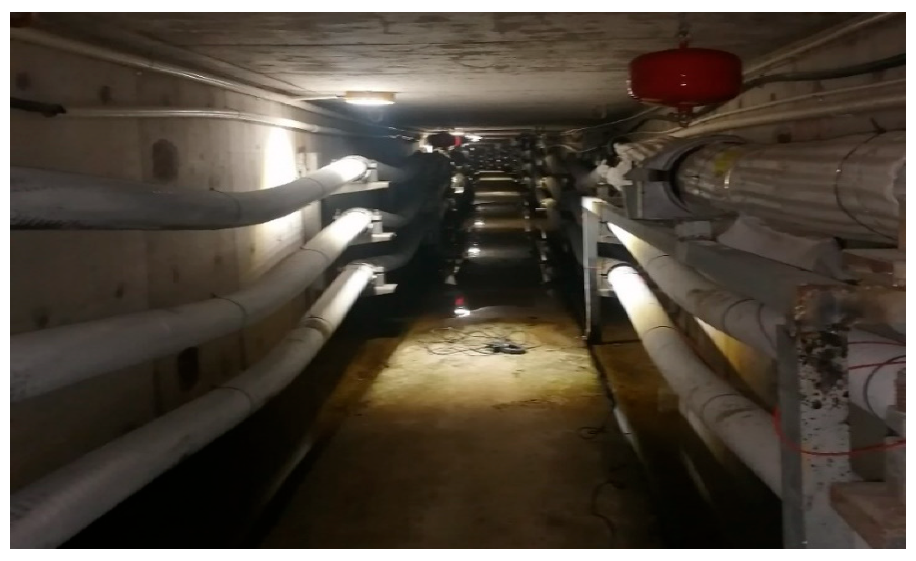
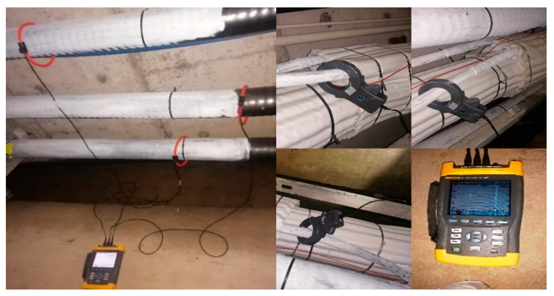
To ensure the accuracy of the harmonic source model in representing the actual harmonic characteristics of electrified railways, harmonic current measurements were conducted on the first cross-bonding section of a 220 kV cable near the traction substation. The tested cable is the widely adopted YJLW03-127/220 kV-1 × 2500 mm2 type in engineering practice. The field test setup is illustrated in Figure 1 and Figure 2.
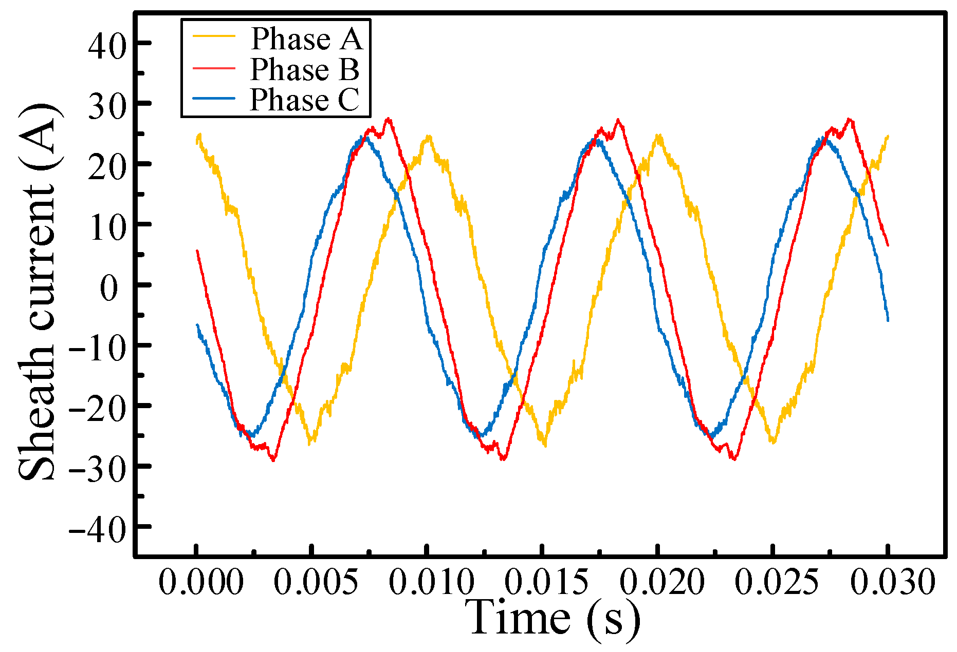
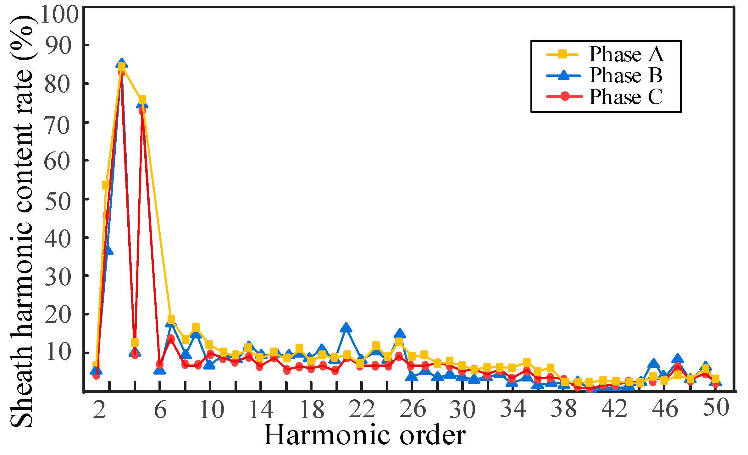
The sheath current waveform within a selected time interval is extracted, as shown in Figure 3. The data corresponding to the most severe harmonic distortion during the measurement period were recorded. The phase conductor currents of phases A, B, and C exhibit differences in both peak amplitude and frequency, indicating that the load currents are unbalanced among the three phases. This phenomenon is attributed to the varying operational states of high-speed trains during the sampling period. A further analysis of the harmonic content for each order is presented in Figure 4. It can be observed that the harmonic current is predominantly composed of harmonics below the 50th order, with low-order odd harmonics being dominant. Among them, the 3rd to 25th odd harmonics are particularly prominent, with the highest content reaching 30%, exceeding the harmonic limit of 1.6%. Additionally, harmonic amplification is observed near the 50th order.
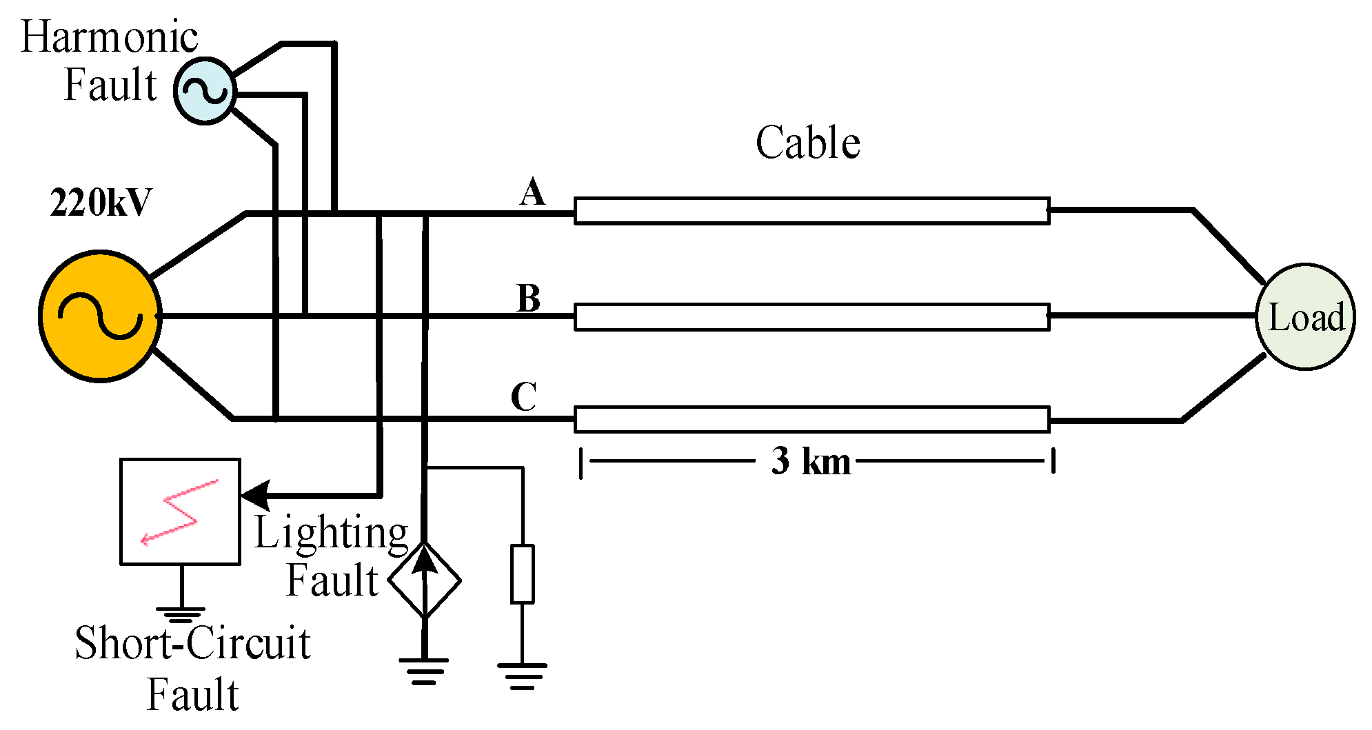
Based on the above analysis of the measured harmonic currents, the harmonic characteristics and order-specific content are incorporated into the modeling framework, providing a realistic foundation for simulating sheath overvoltage in the 220 kV cable system. First, A 220 kV single-core cable, 3 km in total length and segmented every 500 m, is selected as the study object. Then, a simulation model is developed in PSCAD to analyze how overvoltage types, cable length, and grounding configurations affect sheath overvoltage. An overall system model is shown in Figure 5.

2.1. Cable Model

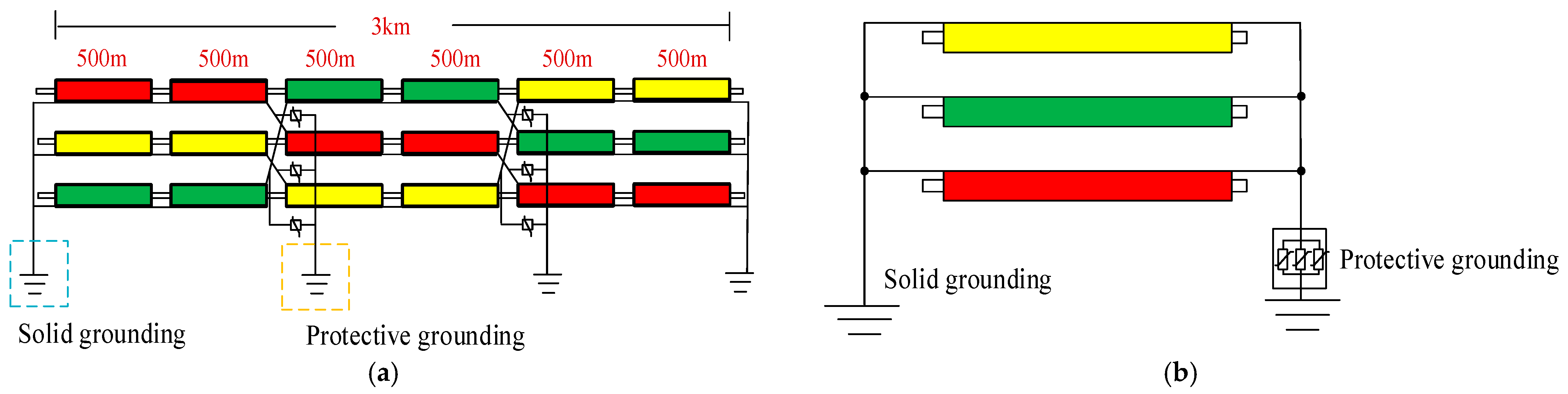
The cable line model incorporates two grounding methods: single-end grounding and cross-bonding, as illustrated in Figure 6. All PSCAD simulations use a fixed time step of 1 μs to accurately capture high-frequency transients. Considering that long lines generally require transposition every 1.2 km, the cross-bonding configuration in this study divides the cable into three equal segments, with phase transposition performed every 1 km. The cable selected is the commonly used model YJLW03-64/220 kV 1 × 400 mm2; the parameters of the cable are given in Table 1. It is modeled using the Fre-Dep (Phase) time-domain approach and consists of a conductor, inner and outer semiconducting layers, main insulation, metallic sheath, and outer jacket.

2.2. Protector Model

The cable sheath protector, which is a type of zinc oxide arrester, is modeled using the BHQ-10/600 arrester model with a rated voltage of 4 kV. According to Ref. [17], parameters of BHQ-10/600 are given in Table 2. According to the protector’s characteristics, the relationship between the maximum power-frequency voltage during a fault and the protector’s rated voltage is as follows:
U m = K U e
where Um is the power-frequency voltage during a fault, Ue is the protector’s rated voltage, K is the coordination factor of power-frequency voltage of the protector, which can be taken as 1.1 to 1.3.
In accordance with the guide for high-voltage cable selection, the coordination factor K for the 220 kV cable sheath protector is taken as 1.2. Consequently, the maximum power-frequency voltage that the sheath protector can withstand is calculated to be 4.8 kV.

2.3. Harmonic Model

Harmonics generated by high-speed trains mainly consist of odd-order components below the 50th order, with high-order harmonics being the key factor contributing to elevated harmonic voltages. Based on this, the harmonic content of the cable core current on the 220 kV side is defined using the following expression:
I t = k = 1 , 3 , 5 , 49 I k s i n ω k t + φ k
where Ik is the amplitude of the kth harmonic, φk is the initial phase of the kth harmonic, and ω k is the angular frequency of the kth harmonic.
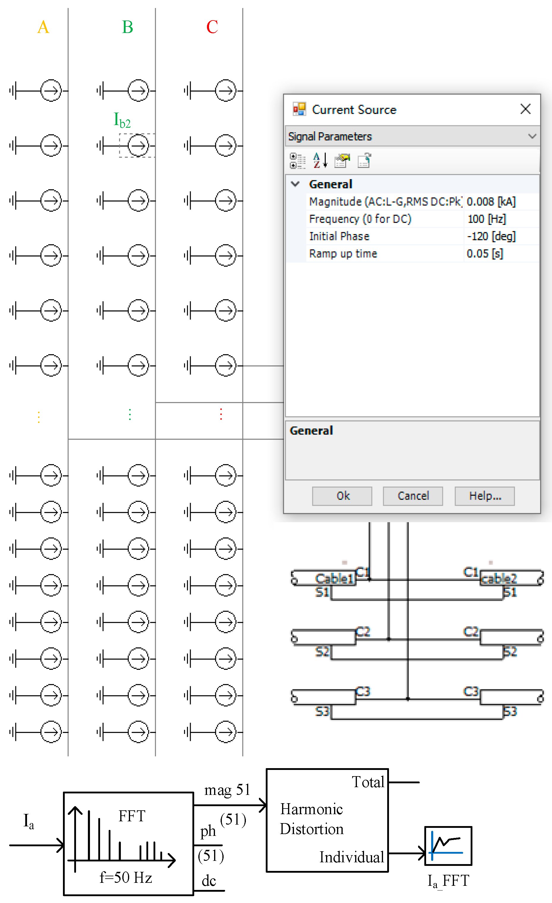
Based on the above derivation, a current injection source containing up to 50th-order harmonics is constructed in the simulation and shown in Figure 7. The total simulation time for harmonic analysis is 0.2 s, and the power-frequency grounding resistance at all points is 0.5 Ω.

2.4. Short-Circuit Model

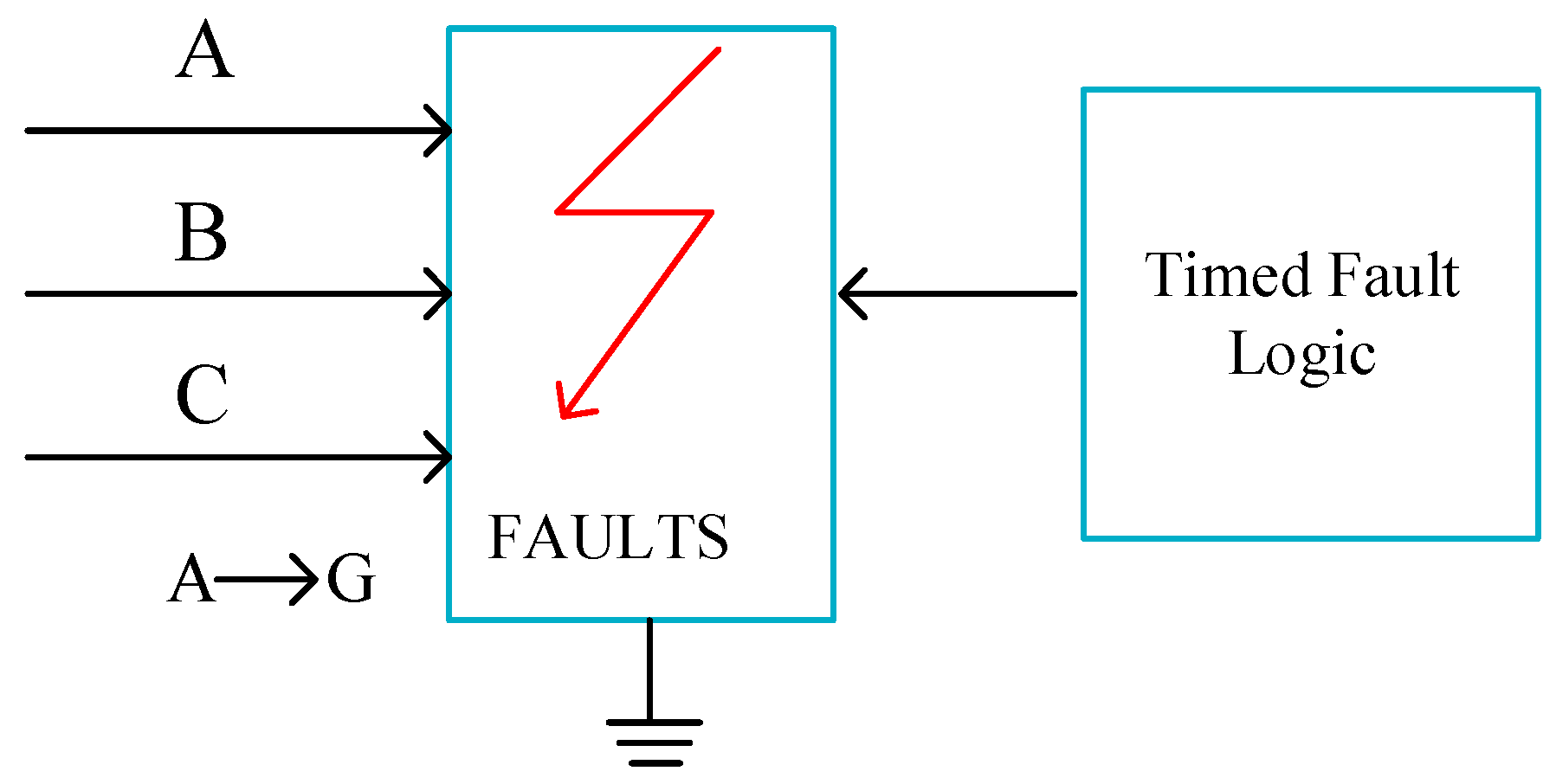
Short circuits are among the common faults of high-voltage cables. When a ground fault occurs on a cable line, the excessive short-circuit current in the conductor induces an excessively high short-circuit voltage on the cable sheath. A single-phase ground fault model for the 220 kV cable was developed in the simulation system and shown in Figure 8. The total simulation time for short-circuit analysis is 0.1 s, and the power-frequency grounding resistance is 0.5 Ω. Assuming a ground fault occurs on phase A at 0.02 s.

2.5. Lightning Model

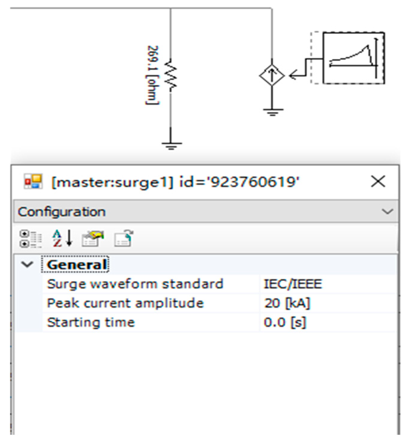
Lightning currents pose severe threats to power cables, potentially causing sheath protectors to fail due to dielectric breakdown. A lightning overvoltage model for 220 kV cable systems was developed in the simulation and shown in Figure 9, considering the worst-case scenario with a standard 1.2/50 μs lightning waveform and an impulse grounding resistance of 0.5 Ω. The total simulation time for lightning analysis is 0.002 s (2 ms). The cable terminal is connected to a 400 Ω load.

3. Characteristic Analysis and Optimization Strategies of Sheath Harmonic Overvoltage

3.1. Analysis of Harmonic Overvoltage Characteristics

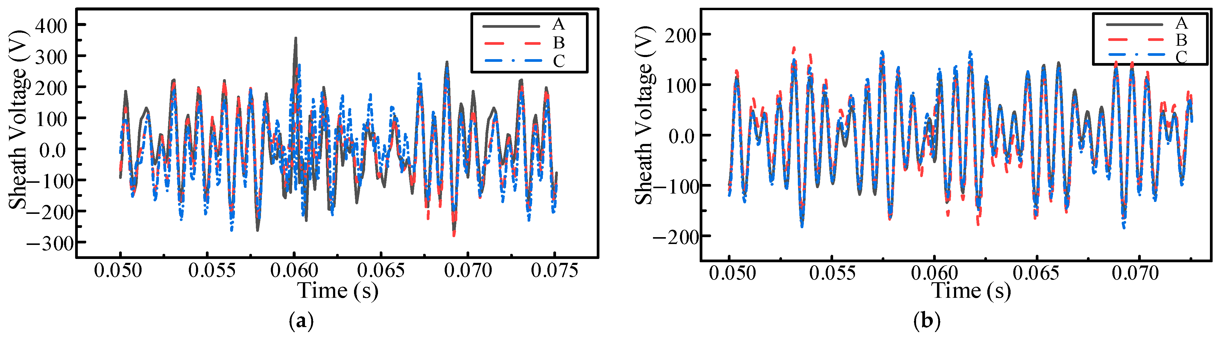
Normally, the voltage on the cable sheath remains below 50 V. Certain typical loads, such as high-speed railways, due to their time-varying nonlinear characteristics, generate high-frequency harmonic interference in the power supply system. To further analyze the characteristics of these intermittent harmonic overvoltages, this paper selects measured railway harmonic data from two time intervals with significantly high-order harmonic content. The harmonic voltage on the sheath obtained through simulation is shown in Figure 10.
The simulation results indicate that intermittent harmonic overvoltages exhibit significant fluctuations, which are attributed to the varying high-speed rail loads at different time intervals. When the high-speed railway load contains substantial harmonics, it leads to severe three-phase current imbalance. This, in turn, increases the harmonic voltage on the sheath. The sheath harmonic voltage reaches a peak of 352 V, far exceeding the 50 V under normal power-frequency conditions.
The sheath protector is designed to limit overvoltages on the sheath caused by lightning strikes or short circuits, typically with an operating threshold above 2 kV. Although the magnitude of harmonic overvoltage generated across the protector far exceeds the 50 V observed under power-frequency conditions, it remains significantly lower than the protector’s operating voltage. As a result, the protector cannot effectively suppress harmonic voltages. Prolonged exposure to harmonic voltage increases power dissipation in the sheath protector, accelerates its aging, and poses a potential safety risk to the whole cable.
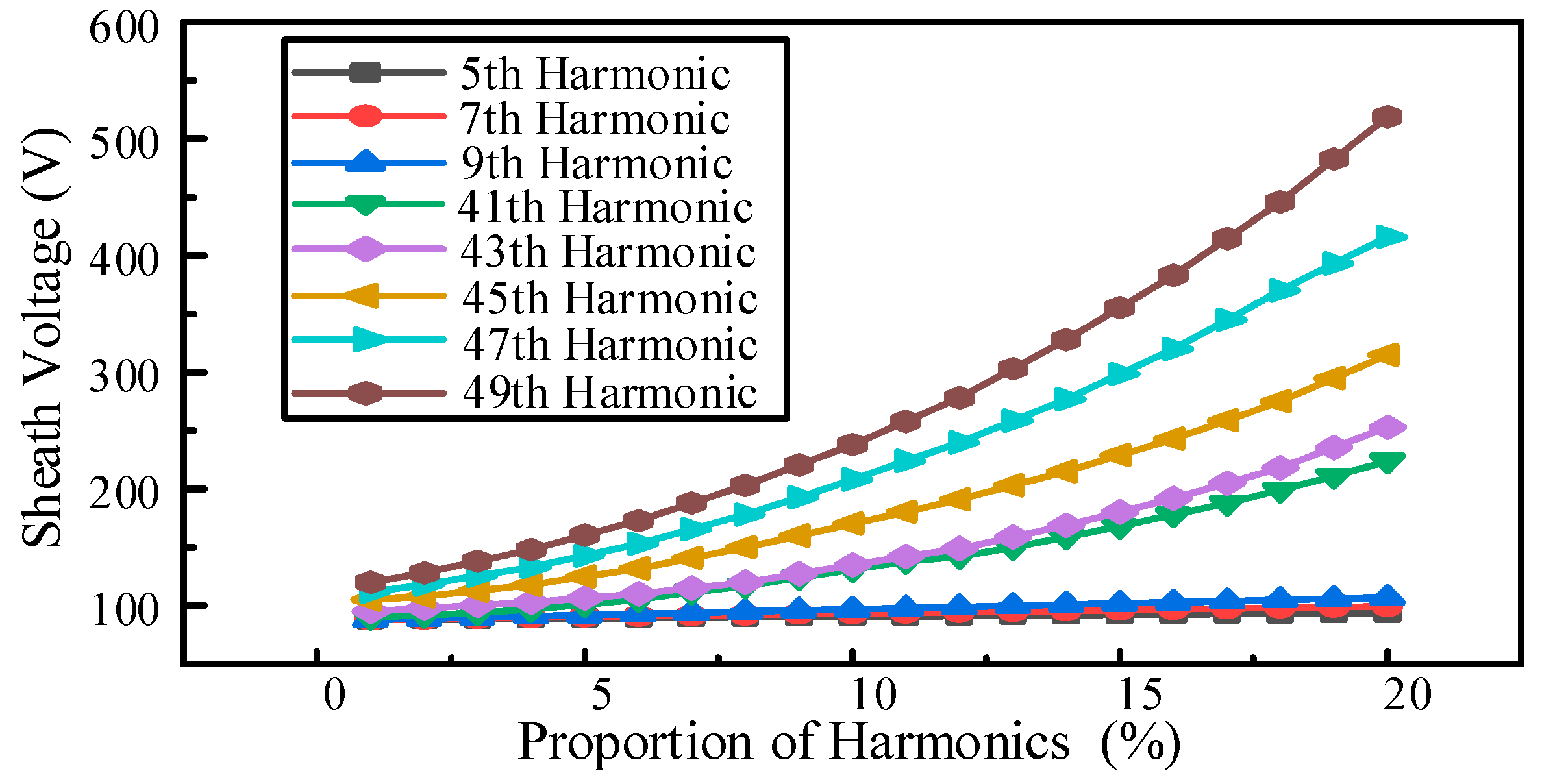
Based on further analysis of the measured harmonic data, the core current of the 220 kV cable on the traction station side is predominantly composed of low-order odd harmonics, with a relatively low content of high-order harmonics. However, due to their higher frequencies, higher-order harmonics can generate significant induced voltages in inductive loops, and their impact may far exceed their proportional share of the current. Therefore, to accurately assess the risk of sheath voltage, the proportion of high-order and low-order harmonics in the harmonic source was adjusted to investigate the variation of sheath voltage with the content of each harmonic current. The results are shown in Figure 11.
It is evident that the content of high-frequency harmonic currents has a significant impact on the sheath voltage. The rate of increase in sheath voltage accelerates with rising harmonic content, and this effect becomes more pronounced as the harmonic frequency increases. Therefore, suppressing or even eliminating higher-order harmonics is an effective measure for optimizing the configuration of the sheath protector.

3.2. Optimization Strategies for Protectors Considering Harmonic Suppression

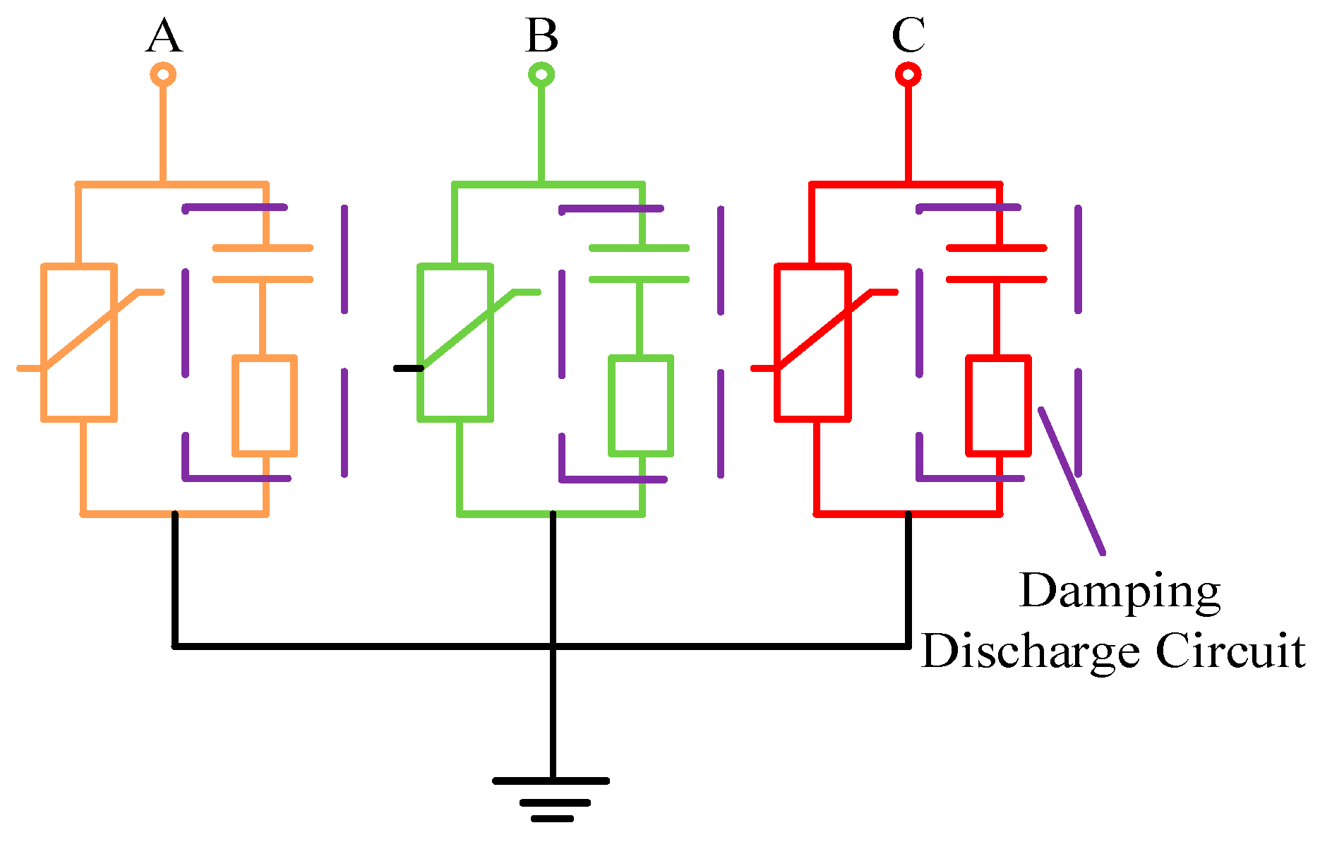
For intermittent harmonic overvoltages, this paper proposes the use of a damping discharge circuit to reduce high-frequency harmonic voltage at the protector terminal. The discharge circuit consists of a discharge capacitor and a resistor, with its structural schematic shown in Figure 12.
The damping discharge circuit can effectively suppress harmonic voltages. By increasing the sheath grounding capacitance, the voltage division of harmonic components on the sheath is reduced. When a discharge capacitor is connected, the voltage at the sheath protector terminal is given by:
U = k = 1 k = n U e k ( 1 1 + j ω ( R d + j ω k L a ) ( C a / 2 + C a ) )
where Uek is the electromagnetic induction voltage of the kth harmonic, ωk is the angular frequency of the kth harmonic, Rd is the equivalent resistance of shield resistance and grounding resistance, La is the sheath inductance, Ca is the sheath-to-ground capacitance and C a is the discharge capacitance.
Factor Z is defined as:
Z = 1 1 + j ω ( R d + j ω k L a ) ( C a / 2 + C a )
It can be seen that the discharge capacitance and harmonic frequency are key factors determining the value of factor Z. When factor Z < 1, the sheath voltage is reduced. Therefore, different capacitance values have varying effects on suppressing sheath harmonic voltages. Additionally, connecting a discharge capacitance alters the resonance condition. By adding a discharge resistance in series with the capacitor branch, new resonances can be prevented, thereby mitigating the impact of intermittent harmonic overvoltages.
The discharge resistance should be selected in conjunction with the effectiveness of the discharge capacitor in suppressing harmonic voltage. When the discharge resistance is connected in series with the capacitor circuit, the voltage division coefficient Z is expressed as:
Z = 1 1 + j ω C a ( R d + j ω k L a ) / ( 1 + j ω k C a R a )
where R a is the discharge resistance of the discharge branch.
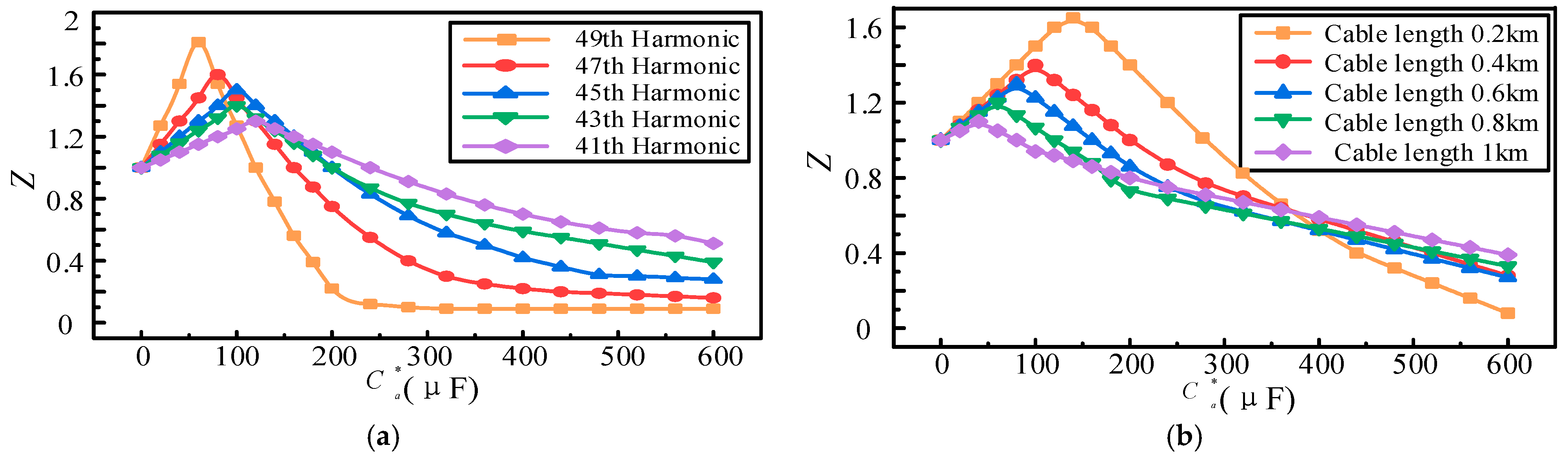
Based on Ref. [18], high-order harmonics are identified as the key contributors to elevated sheath harmonic voltages. Ref. [4] is used to analyze the influence of the discharge capacitor on factor Z under varying cable lengths and harmonic frequencies, as illustrated in Figure 13.
The results show that factor Z initially increases with the rise in the discharge capacitance. Once the discharge capacitance exceeds a certain threshold, Z begins to decline. As shown in Figure 13a, when the discharge capacitance exceeds 150 μF, its suppressive effect on harmonic voltage is significantly enhanced with increasing frequency. When the capacitance reaches 400 μF, the suppression effect gradually tends to saturate. The results quantitatively demonstrate that increasing damping capacitance from 0 to 400 µF reduces the harmonic voltage division factor Z by approximately 85% (from 1.0 to 0.15) for high-order harmonics (above 35th order). This nonlinear relationship indicates a saturation point near 400 μF, beyond which the marginal benefit diminishes.
Figure 13b indicates that once the discharge capacitance surpasses 400 μF, its effectiveness in suppressing harmonic voltage diminishes as the cable length increases. Based on the above analysis, for the simulated cable segment of 0.5 km in this study, a damping capacitance of 400 μF is recommended to effectively suppress high-frequency harmonic voltage in the sheath.
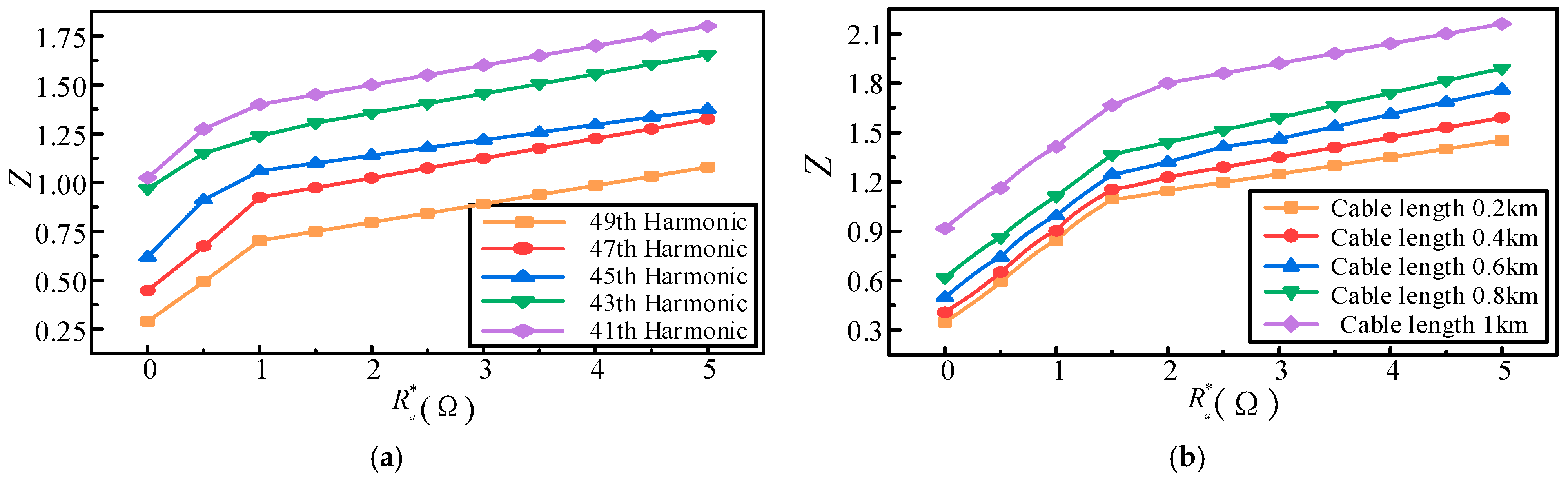
Furthermore, based on Formula (5), the influence of different parameters on the selection of discharge resistance is shown in Figure 14.
It can be seen that for high-order harmonic suppression, the discharge resistance should be kept below 0.5 Ω, ensuring that factor Z is less than 1. Figure 14b further reveals that with a fixed discharge resistance, harmonic voltage suppression efficacy diminishes as cable length increases. Consequently, for the 220 kV cable system under study, the optimal discharge resistance range is 0.1–0.5 Ω. This establishes an explicit design margin: selecting discharge resistance outside this range would degrade suppression efficacy by over 40%, failing to meet the harmonic mitigation target.

4. Characteristic Analysis and Optimization Strategies of Sheath Overvoltage

4.1. Analysis of Short-Circuit Overvoltage Characteristics

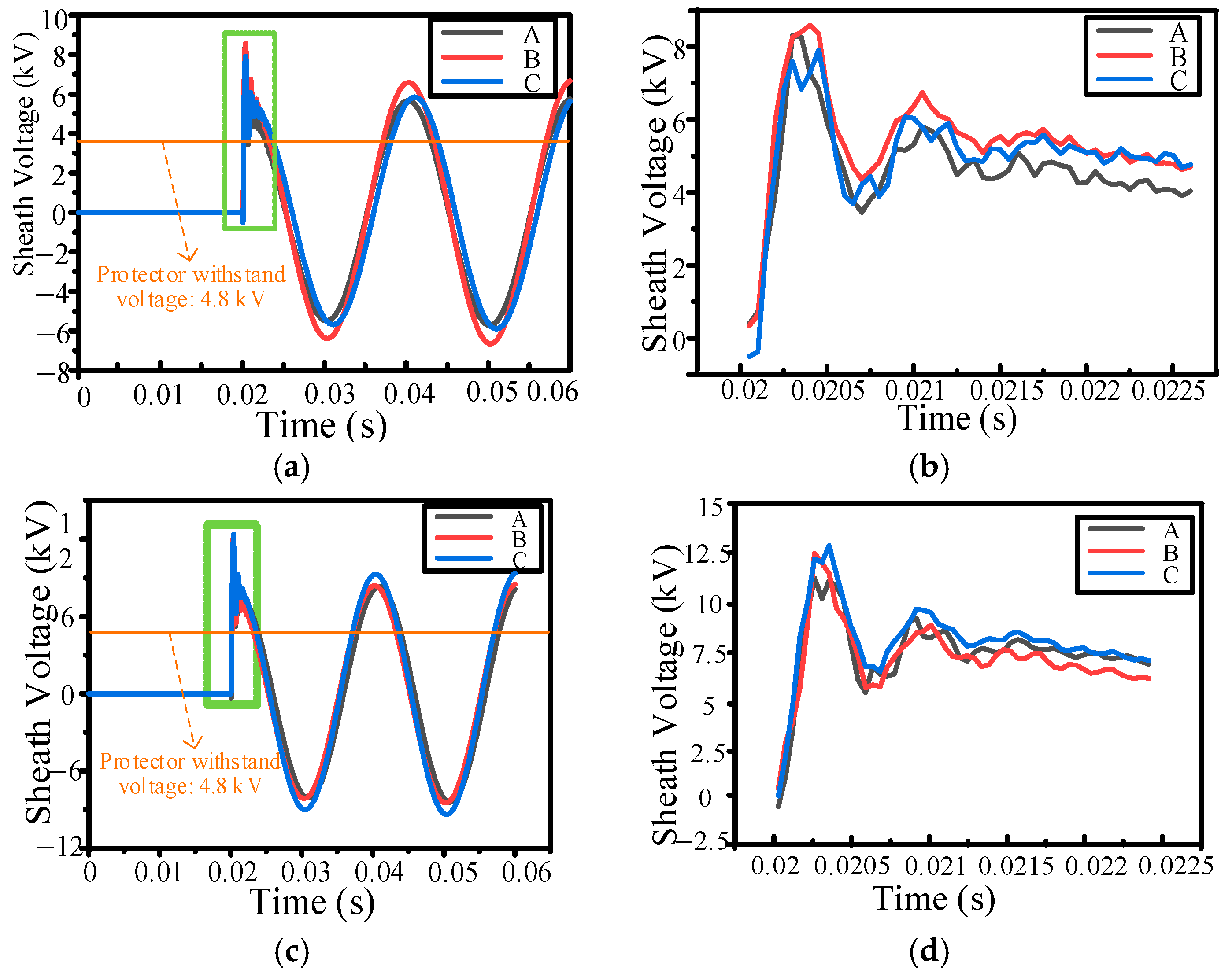
Short-circuit faults frequently occur in cable grounding systems, with single-phase ground faults representing the most severe scenario. If not cleared promptly, sustained overvoltage can cause excessive energy accumulation in the protector, leading to thermal breakdown. A single-phase ground fault model for the 220 kV cable was developed in the simulation system. Assuming a ground fault occurs on phase A at 0.02 s with short-circuit currents of 20 kA and 30 kA, the resulting sheath overvoltage characteristics are presented in Figure 15.
It is evident that when a short-circuit fault occurs, the abrupt change in current causes voltage fluctuations across the cable’s inductance and capacitance, resulting in a transient overvoltage with an instantaneous overshoot being induced on the sheath. As the short-circuit current increases, the sheath overvoltage also rises significantly. When the short-circuit current reaches 30 kA, the peak sheath overvoltage reaches 13.5 kV, far exceeding the protector’s maximum withstand power-frequency voltage of 4.8 kV, thereby endangering the insulation of the sheath protector.
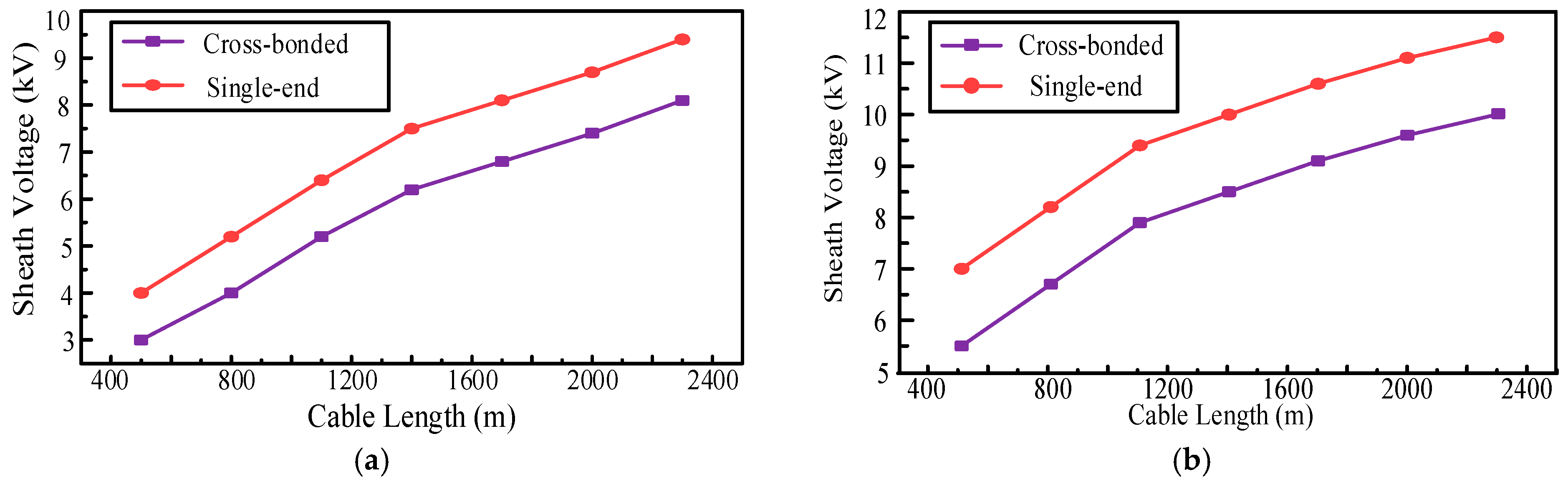
Keeping all other conditions unchanged, the effect of cable length on sheath voltage with different grounding configurations is investigated under short-circuit currents of 20 kA and 30 kA. The results are presented in Figure 16.
The results demonstrate that sheath overvoltage increases with cable length, though this growth trend gradually attenuates due to the suppressive feature of the protector. Comparing the two fault current levels, higher short-circuit currents result in faster overvoltage growth. Grounding configuration also plays a significant role: under 30 kA and 2.3 km cable length, the peak sheath overvoltage under a single-end grounding system reaches 11.5 kV, compared with 9.6 kV under a cross-bonded grounding system. Thus, both cable length and grounding configuration are critical factors in determining protector selection and configuration.

4.2. Analysis of Lightning Overvoltage Characteristics

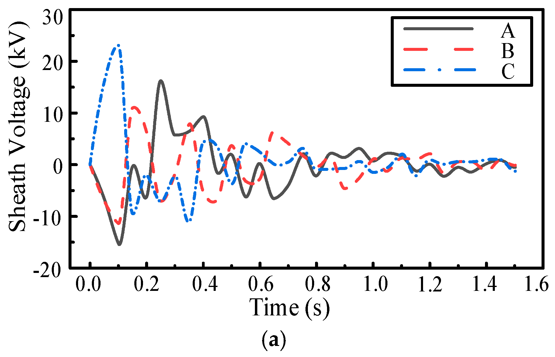
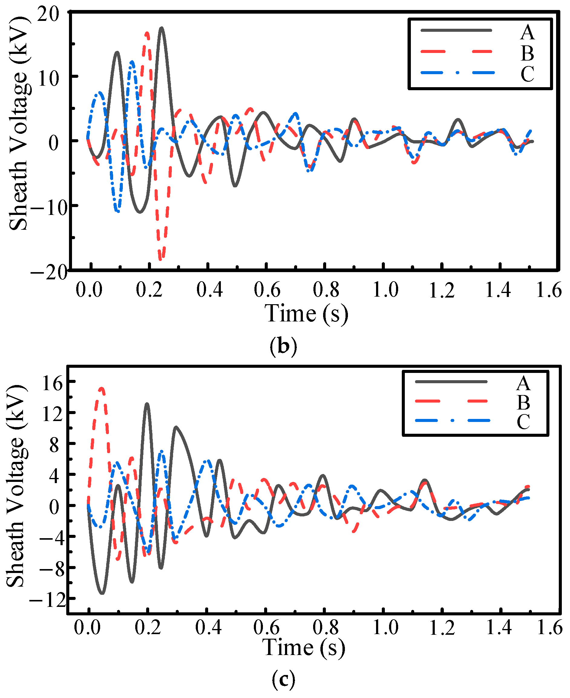
Lightning currents pose severe threats to power cables, potentially causing sheath protectors to fail due to dielectric breakdown. A lightning overvoltage model for 220 kV cable systems was developed in the simulation, considering the worst-case scenario with a standard 1.2/50 μs lightning waveform and an impulse grounding resistance of 0.5 Ω. The cable terminal is connected to a 400 Ω load. Both cross-bonded and single-end grounding configurations are analyzed, with 300 m cable segments. Figure 17 shows the sheath overvoltage under lightning intrusion.
The results show that lightning currents induce significant overvoltages on the sheaths. For the cross-bonded grounding configuration, the peak sheath voltages at the first and second bonding points are 18.4 kV and 15.6 kV, respectively, with a noticeable imbalance among the three phases. In contrast, the single-end grounding configuration results in a peak sheath voltage of 24.5 kV, considerably higher than the cross-bonded case. Moreover, the strong oscillation present in the transient component of the sheath voltage waveform poses a significant risk to cable insulation, thereby threatening the safe operation of the system.
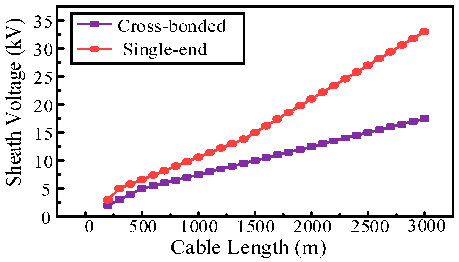
Keeping all other conditions unchanged, the effect of cable length on sheath voltage under different grounding configurations is investigated. The results are presented in Figure 18.
The results show that sheath overvoltage exhibits a near-linear correlation with cable length. Under 3 km cable length, the sheath overvoltage reaches 33.4 kV in a single-end grounding system, compared with 17.5 kV in a cross-bonded grounding system. Thereby, both cable length and grounding configuration are factors for protector configuration.
Furthermore, as illustrated in Figure 17 and Figure 19, the sheath overvoltage exhibits a consistent increasing trend with cable length under both short-circuit and lightning conditions. This clear parametric sensitivity confirms that cable length is a dominant factor, rather than a scenario-specific observation. Meanwhile, the results also demonstrate that cross-bonded grounding consistently yields lower sheath overvoltage than single-end grounding across various cable lengths. This persistent trend validates the general superiority of the cross-bonded configuration for voltage suppression.

4.3. Optimization Strategies for Protectors Considering Overvoltage Influencing

For scenarios involving high-amplitude overvoltages such as lightning strikes and short-circuits, numerical simulations were conducted to identify key factors influencing sheath protector performance, including cable length and grounding configuration optimization, with the aim of reducing induced sheath overvoltages.
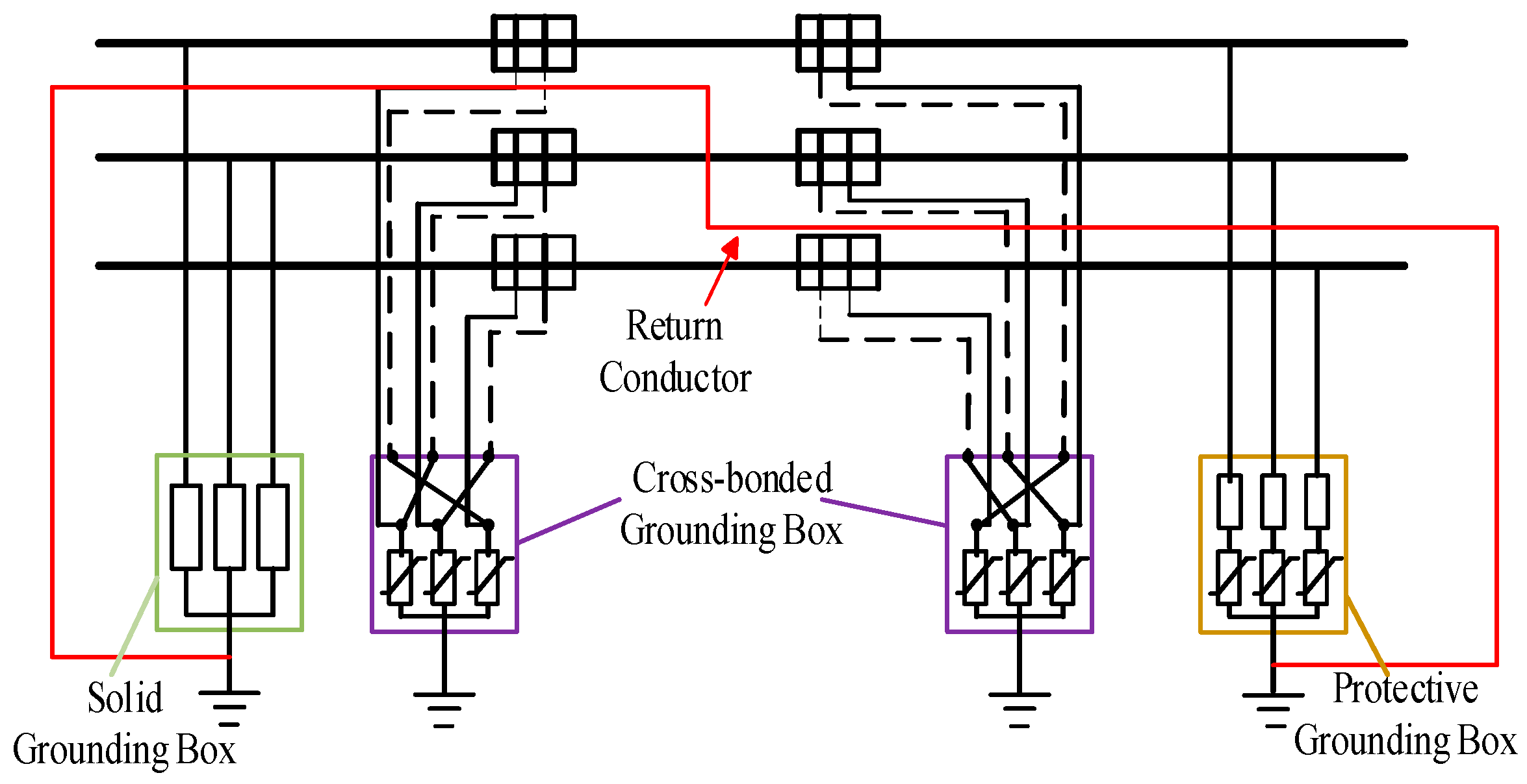
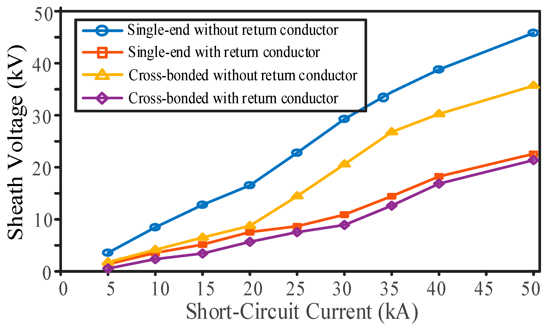
Building upon this, in addition to the cross-bonding grounding configuration, this chapter further optimizes the grounding system by incorporating a return conductor. The return conductor can provide a low-impedance path, diverting fault current away from the ground to further suppress sheath overvoltage. Figure 19 illustrates the return conductor installation scheme. This study examines single-phase short-circuit conditions, comparing sheath overvoltage levels with and without return conductors through simulation.
Taking a 1 km, 220 kV cable as an example, the sheath overvoltage levels under different grounding configurations are tested, with results shown in Figure 20. It is evident that the sheath overvoltage in the cross-bonded configuration is significantly lower than in the single-end grounded configuration. The test result also clarifies the quantitative impact of the return conductor, showing a notable and consistent suppression effect across different short-circuit current levels, particularly under high-current conditions, thereby generalizing the benefit of incorporating a return conductor.
Moreover, the introduction of a return conductor shows a notable suppression effect on sheath overvoltages, and this effect becomes more pronounced as the short-circuit current increases. When the fault current exceeds 20 kA, the rate of increase in sheath overvoltage rises sharply regardless of the grounding scheme, indicating that the energy absorbed by the sheath protector will also increase substantially.

4.4. Optimization Strategies for Energy Absorption

The energy absorbed by a sheath protector is closely related to the short-circuit current, sheath voltage, and fault duration. As the short-circuit current increases, the energy absorbed by the protector rises significantly, resulting in a greater risk of thermal breakdown. Therefore, another optimization approach is to install multiple sheath protectors in parallel to share the energy absorption burden during operation.
When the time-varying current flowing through the sheath protector and its terminal voltage are known, the energy absorbed by the protector during operation can be determined. The calculation formula is as follows:
W = t 1 t 2 U t I t d t
where the duration from t1 to t2 represents the existence time of the short-circuit or lightning strike current. U(t) and I(t) are the instantaneous voltage across and current through the protector.
Under maximum conditions, the energy absorption capacity of the protector is given by:
E m = max t 0 t t 1 ( t 1 t U t I t d t )
where U is the residual voltage under the nominal discharge current of the protector, I is the current-handling capability for a 2 ms rectangular wave, and t is the duration of the rectangular current pulse.
Taking the protector model BHQ-10/600 selected in this study as an example, its 2 ms rectangular wave current rating is 600 A, and the residual voltage under the nominal discharge current is 10 kV. Therefore, its energy absorption capacity can be calculated as 12 kJ.
When the short-circuit current is relatively low, multiple protectors can be connected in parallel at a common node. This method is advantageous due to its low cost and simple structure, which enhances the overall energy absorption capacity and system stability.
Taking a single-phase short-circuit scenario as an example, a 220 kV cable of 500 m is modeled using BHQ-7/600 and BHQ-10/600 type protectors. According to Ref. [6], the energy absorbed under different short-circuit current levels is simulated, as shown in Table 3. When the short-circuit current reaches 20 kA, the energy absorption by the protector increases dramatically compared with lower current levels, which is consistent with the simulation results in Figure 20. At this point, the addition of more protectors should be considered. However, when the short-circuit current reaches 40 kA, the energy absorption demand far exceeds the capacity of a single protector, requiring dozens of protectors in parallel, making it impractical for actual implementation.
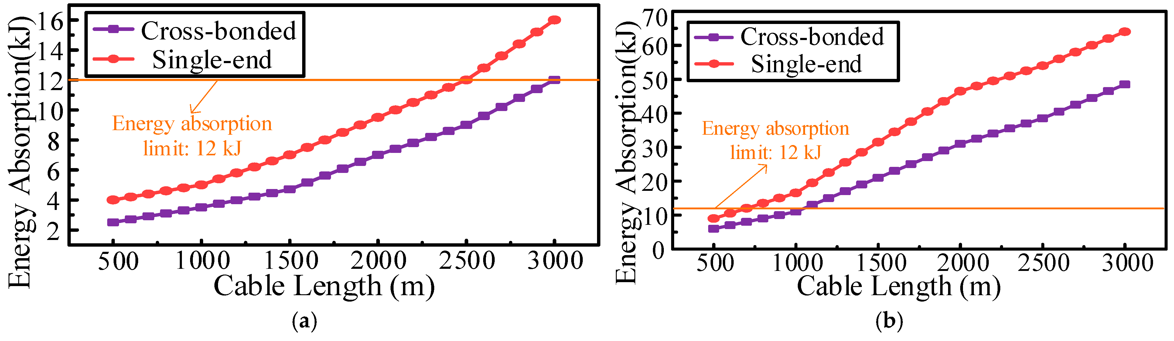
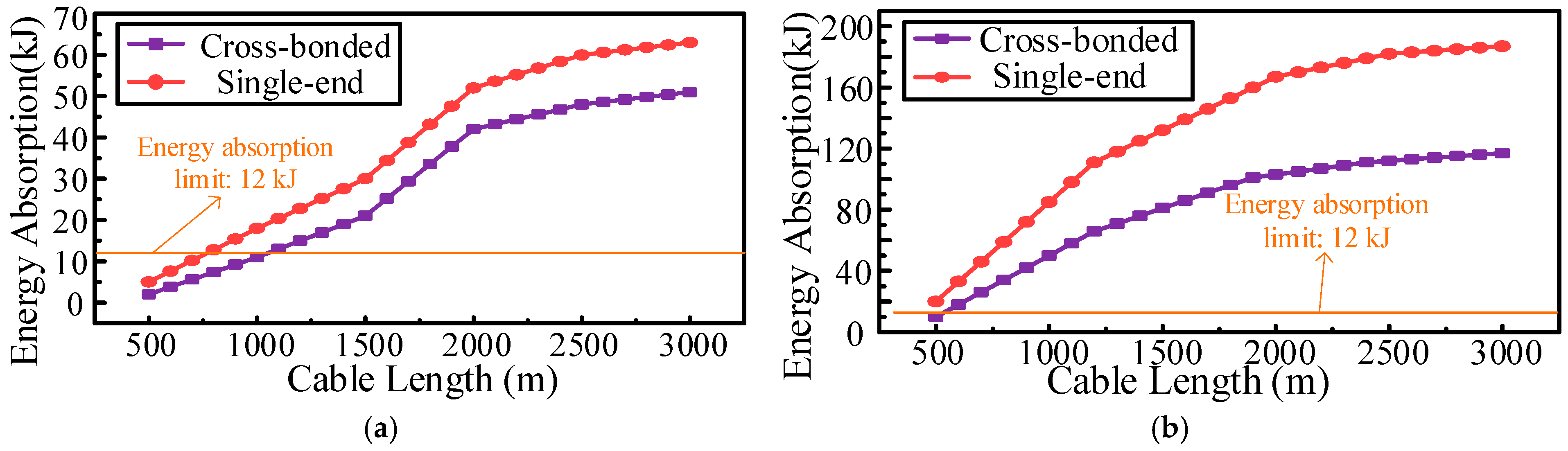
Preliminary simulations show that the sheath overvoltages under lightning strikes and short circuits are the most severe, leading to the highest energy absorption by the protectors. The absorbed energy also varies with cable length and grounding configuration. Without adding parallel protectors, studying the influence of cable length and grounding configuration on energy absorption characteristics can provide a basis for protector configuration and lightning protection performance enhancement. This paper analyzes the relationship between protector energy absorption and cable length under both lightning and short-circuit conditions, with results shown in Figure 21 and Figure 22.
It is evident that as cable length increases, the energy absorbed by the protector also increases. Under different grounding configurations, single-end grounding results in higher energy absorption, and the difference becomes more pronounced with higher short-circuit currents, indicating the advantages of cross-bonded grounding. This suggests that even without adding protectors, energy optimization can be achieved by appropriately designing cable lengths and grounding configurations. At a short-circuit current of 20 kA, the protector’s energy limit of 12 kJ corresponds to maximum cable lengths of 0.75 km for a single-end grounding system and 1.05 km for a cross-bonded grounding system.
Table 3 provides a normalized comparison of energy absorption relative to the protector’s maximum withstand capability of 12 kJ. Under a 20 kA short-circuit current, the absorbed energy for single-end grounding reaches 67.56 kJ, exceeding the design limit by a factor of 5.6 and indicating a severe risk of thermal breakdown. In contrast, cross-bonded grounding reduces the energy demand to 53.56 kJ, corresponding to a 20% reduction. Nevertheless, this value still exceeds the 12 kJ threshold. This quantitative margin analysis demonstrates that, for fault currents equal to or greater than 20 kA, relying solely on grounding optimization is insufficient to ensure safe operation.
In summary, for intermittent harmonic overvoltages, the protector configuration can be optimized by incorporating a damping discharge circuit. For scenarios with high-amplitude overvoltages such as short circuits and lightning strikes, cable length and grounding configurations can be adjusted to optimize the line configuration where the protector is installed. In cases where large fault currents occur, protectors with higher current-carrying capacity or multiple protectors in parallel may be considered to improve reliability.

5. Simulation-Based Case Study and Engineering Applicability Analysis

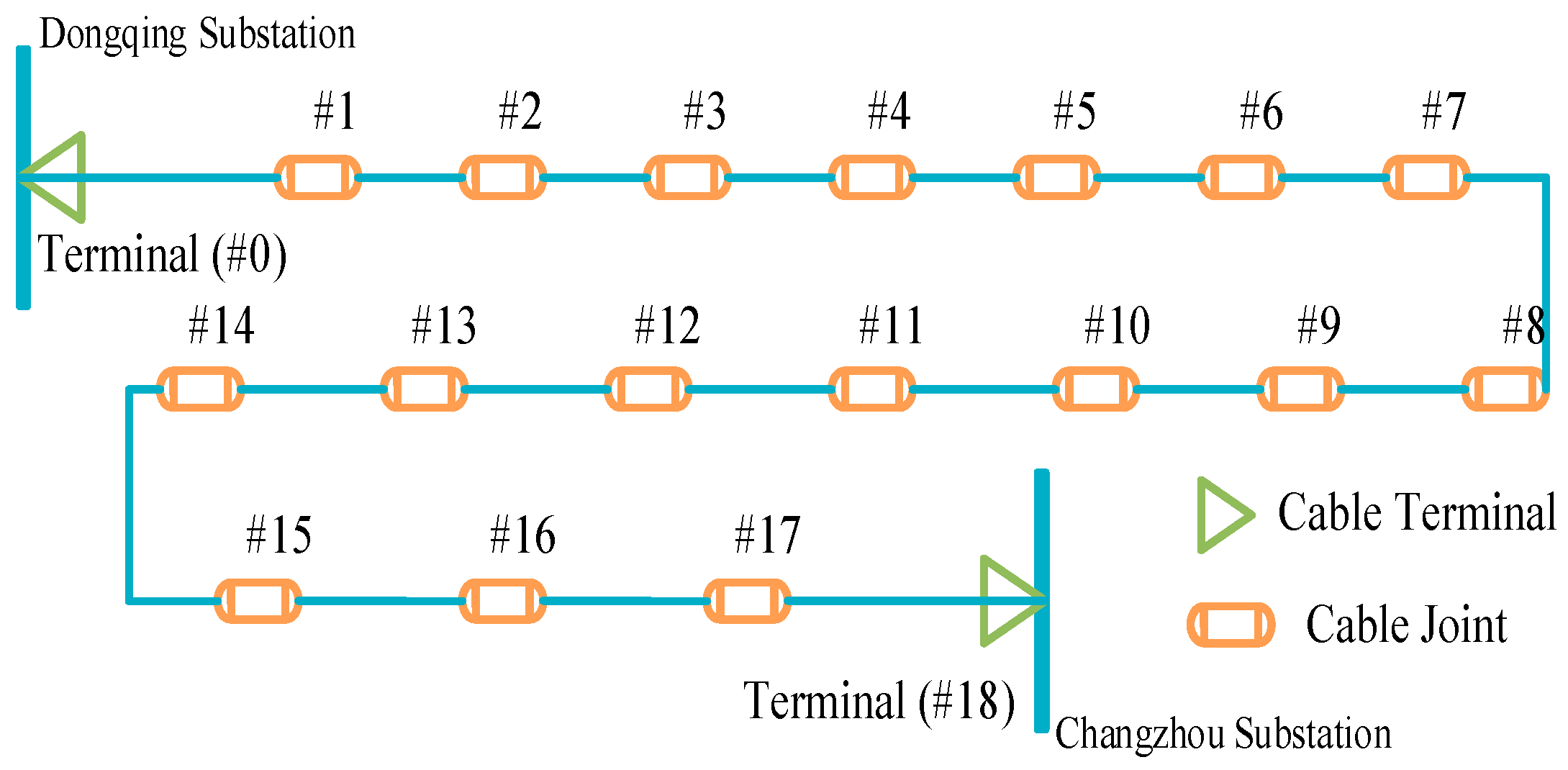
An actual traction substation cable line project is taken as the engineering background. Its actual layout and structural parameters are adopted to establish a simulation model for analyzing the sheath voltage characteristics under harmonic, lightning, and short-circuit conditions. The cable used is model ZR-YJLW03-127/220-1 × 1600, and the layout is shown in Figure 23. Related cable segment parameters are listed in Table 4. In the simulation, two terminal ends, #6 and #13, are directly grounded, while the remaining sections are grounded through sheath protectors.

5.1. Simulation Analysis of Damping Discharge Circuit Effect

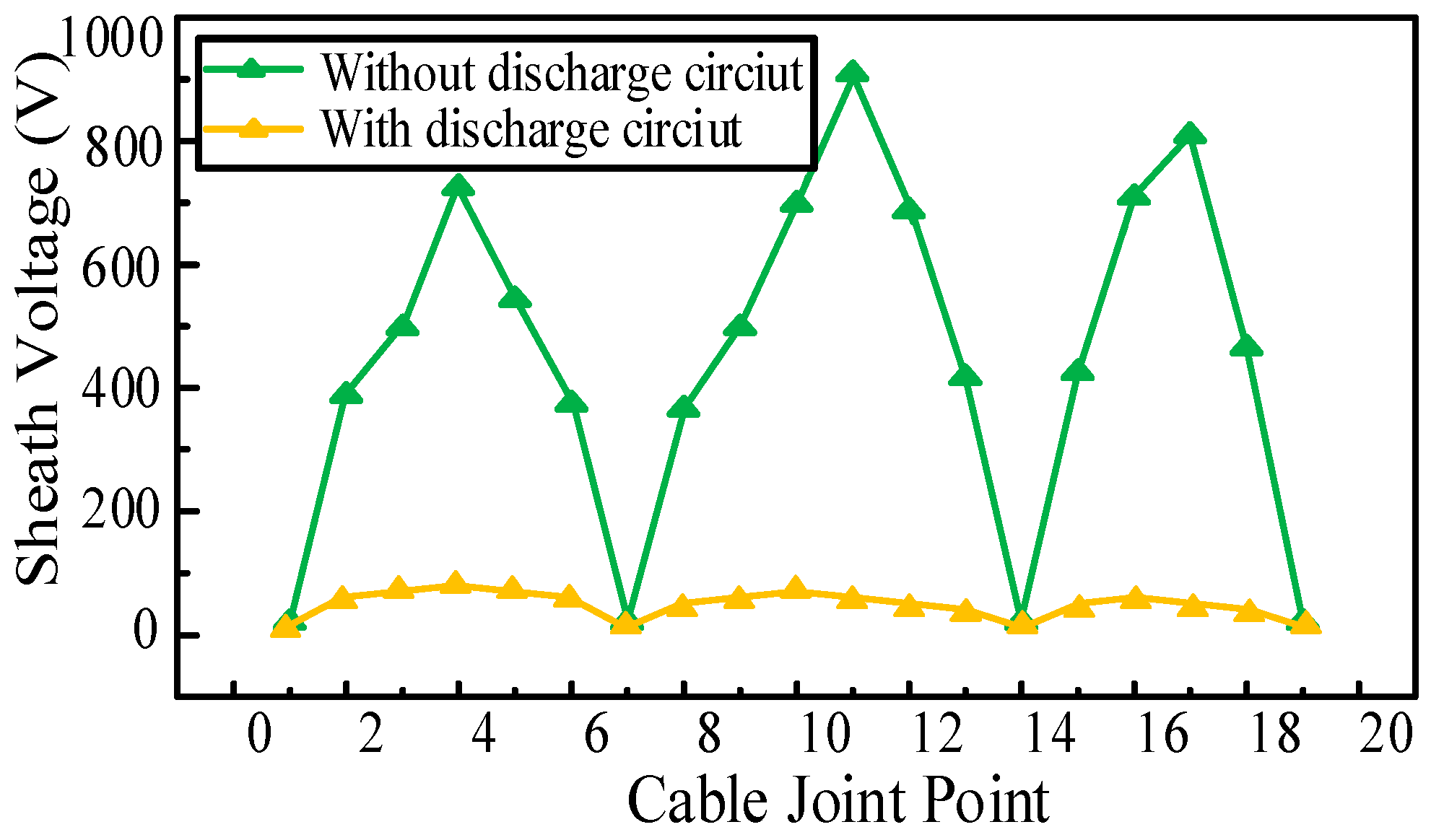
Typical time-period operating data with high-order harmonic content is selected. The harmonic voltage on the sheath is simulated before and after connecting the damping discharge circuit. The distribution of the sheath voltage along the line is shown in Figure 24.
It can be observed that after introducing the damping discharge circuit, the harmonic voltage on the cable sheath is significantly reduced, with sheath voltages ranging between 30 V and 60 V, whereas the maximum harmonic voltage in the original circuit reached 900 V. This indicates that the high-frequency harmonic voltages induced on the sheath are effectively suppressed.

5.2. Simulation Analysis of Cable Length and Grounding Configuration Optimization

The established model was then used to conduct transient simulation studies on sheath overvoltage characteristics under various conditions. The specific operating scenarios are configured as follows:
i.
Short-circuit condition: A single-phase-to-ground fault is simulated on phase A at 0.02 s.
ii.
Lightning condition: A standard lightning current waveform of 1.2/50 μs is introduced at the cable’s leading section, with the grounding resistance at the surge point set to 0.5 Ω. A load is connected at the cable terminal, with a load impedance of 0.4 kΩ.
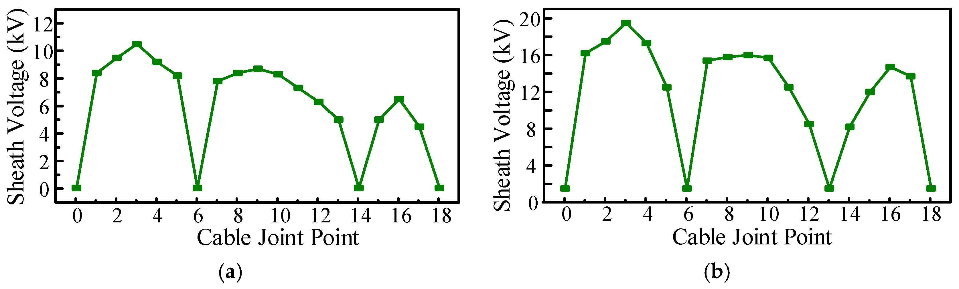
The distribution of sheath voltage along the cable line is shown in Figure 25. The results indicate that under both conditions, the sheath overvoltage is relatively low at direct grounding points, while it rises significantly at non-direct grounding points where sheath protectors are used. In particular, in long sections with consecutive non-direct grounding, the sheath overvoltage increases noticeably, with the peak voltages of all three phases concentrated near the sheath protector locations. These findings further demonstrate that cable parameters and grounding arrangements have a critical impact on the optimization of sheath protector configuration and must not be overlooked.
Further calculation of the energy absorbed by the protectors within 0.1 s of operation revealed that under short-circuit conditions, some protectors near the traction transformer side exceeded the 12 kJ threshold. Therefore, it is feasible to consider appropriately reducing the cable length or adding a return conductor for the line sections close to the traction station. Under lightning strike conditions, the protectors on phase A along the entire line exceeded the energy threshold, suggesting that replacing them with protectors having a higher current-handling capacity could be considered.

6. Conclusions

This study investigated the generation mechanism of overvoltages in the sheaths of 220 kV cable systems, focusing on the characteristics of sheath overvoltages induced by harmonics, short-circuit faults, and lightning strikes. Based on simulation analysis using a YJLW03-64/220 kV 1 × 400 mm2 cable model in PSCAD, a set of engineering configuration optimization schemes for sheath voltage protectors was proposed. The main conclusions are as follows:
i.
High-order harmonics significantly amplify sheath harmonic voltages due to high-frequency inductive effects, exceeding the contribution of low-order harmonics. Based on this mechanism, a damping discharge circuit composed of a capacitor and a resistor is proposed as a general suppression strategy. For the 0.5 km cable segment studied, parameter optimization shows that setting the capacitance to 400 μF and the resistance to 0.1–0.5 Ω reduces the voltage division factor below 0.15, effectively mitigating high-frequency overvoltages.
ii.
Multi-parameter simulations identify key factors affecting sheath voltage and protector energy absorption. Peak sheath overvoltage increases with cable length, while grounding configuration modulates this trend. Cross-bonded grounding provides superior voltage suppression compared to single-end grounding due to its phase transposition effect. For the specific configuration studied, under a 30 kA short-circuit current, cross-bonding reduces the peak sheath overvoltage from 11.5 kV to 9.6 kV, and the addition of a return conductor further lowers it by 10–15%.
iii.
Under high-fault-current conditions, if the energy absorption capability of the protector is exceeded, thermal breakdown may occur. For the modeled system, mitigation can be achieved by selecting protectors with higher continuous current ratings or by installing multiple protectors in parallel to enhance energy-handling capacity.

Author Contributions

Conceptualization, X.J. and Y.L.; methodology, X.J.; software, X.J.; validation, X.J.; formal analysis, X.J.; investigation, X.J.; resources, Y.L.; data curation, X.J.; writing—original draft preparation, X.J.; writing—review and editing, Y.L. and Q.L.; visualization, X.J.; supervision, Y.L.; project administration, X.J. and Y.L.; funding acquisition, Y.L. All authors have read and agreed to the published version of the manuscript.

Funding

This research received no external funding.

Data Availability Statement

The original contributions presented in this study are included in the article. Further inquiries can be directed to the corresponding author.

Conflicts of Interest

Qiran Li is employed by Tangshan Power Supply Company, State Grid Jibei Electric Power Co. Ltd. The remaining authors declare that the research was conducted in the absence of any commercial or financial relationships that could be construed as a potential conflict of interest.

References

  1. Hu, R.; Liu, G.; Huang, C.; Xu, Z.; Zhou, W. Power cable fired by transient arcing below the action value of relay protection: An analysis of a medium-voltage cable joint breakdown fault. Eng. Fail. Anal. 2023, 145, 107028. [Google Scholar] [CrossRef] [Scilit]
  2. Liu, J.; Wu, S.; Zhang, Q.; Liu, Z.; Wang, H. Harmonic instability analysis of wind farms and electrified railways jointly connected to the power grid. Power Syst. Technol. 2025, 49, 686–698. (In Chinese) [Google Scholar] [CrossRef] [Scilit]
  3. Wang, H.; Zhou, W.; Chen, J.; Cao, J.; Zhou, C. Analytical solution of the mutual inductance of a HV single conductor cable with corrugated metallic sheath. Trans. China Electrotech. Soc. 2020, 35, 3369–3376. (In Chinese) [Google Scholar] [CrossRef] [Scilit]
  4. Cao, X.; Yi, Z.; Chen, K.; Gao, Z.; Yang, J. Lightning overvoltage and protection measures of high-speed railway feeder cable. High Volt. Eng. 2016, 42, 619–626. (In Chinese) [Google Scholar] [CrossRef]
  5. Wang, W.; Yan, X.; Li, S.; Zhang, L.; Ouyang, J.; Ni, X. Failure of submarine cables used in high-voltage power transmission: Characteristics, mechanisms, key issues and prospects. IET Gener. Transm. Distrib. 2021, 15, 1387–1402. [Google Scholar] [CrossRef] [Scilit]
  6. Shaban, M.; Salam, M.A.; Ang, S.P.; Voon, W. Induced sheath voltage in power cables: A review. Renew. Sustain. Energy Rev. 2016, 62, 1236–1251. [Google Scholar] [CrossRef] [Scilit]
  7. Barakou, F.; Vertkas, A.; Wu, L.; Wouters, P.A.A.F.; Steennis, E.F. Transient modeling and sensitivity analysis of cable system parameters. In Proceedings of the 2016 51st International Universities Power Engineering Conference (UPEC), Coimbra, Portugal, 6–9 September 2016; pp. 1–6. [Google Scholar] [CrossRef] [Scilit]
  8. Alizadeh, R.; Mirzaie, M. The effects of cable characteristics on maximum overvoltage in combined overhead/cable lines protected by surge arresters. IIUM Eng. J. 2018, 19, 104–116. [Google Scholar] [CrossRef] [Scilit]
  9. Alatawneh, N. Effects of cable insulations’ physical and geometrical parameters on sheath transients and insulation losses. Int. J. Electr. Power Energy Syst. 2019, 110, 95–106. [Google Scholar] [CrossRef] [Scilit]
  10. Zhou, Z.; Liu, X.; Wang, S.; Zhu, C.; Liu, H.; Song, C. Simulation calculation of transient voltages on insulation and sheath along 500 kV XLPE submarine cable. High Volt. Eng. 2018, 44, 2725–2731. (In Chinese) [Google Scholar] [CrossRef]
  11. Fu, S.; He, G.; Xu, J.; Deng, X.; Yang, K.; Li, J. Transient characteristic analysis and parameter optimization of sheath protector for large-length high voltage cable. Power Syst. Clean Energy 2021, 37, 32–41. (In Chinese) [Google Scholar]
  12. Chen, P.; Xue, Q.; Luo, Y.; Zhang, C. Overvoltage protection for sheath layer of single core cable. High Volt. Eng. 2004, 30, 6–7. (In Chinese) [Google Scholar] [CrossRef]
  13. Zhang, H.; Huang, J.; Niu, H.; Guo, R. Sheath protector parameter configuration of high voltage cable with decreased insulation. South. Power Syst. Technol. 2017, 11, 34–40. (In Chinese) [Google Scholar] [CrossRef]
  14. Luo, J.; Zhou, Z.; Li, H.; Luo, M. Technical parameters design of over voltage protector for single-core power cable shield sheath. High Volt. Eng. 2008, 34, 355–358. (In Chinese) [Google Scholar] [CrossRef]
  15. Liang, X.; Wang, Y.; Zhang, L. Sheath overvoltage characteristics for single-phase ground fault in 220kV power cable. Eng. J. Wuhan Univ. 2013, 46, 747–751. (In Chinese) [Google Scholar]
  16. Zhong, X.; Zhou, L.; Liu, T.; He, T.; Pang, W.; Chen, J. Research on protection measure for VFTO of 1000kV GIS Substation. Insul. Surge Arresters 2013, 6, 119–123. (In Chinese) [Google Scholar] [CrossRef]
  17. Cao, J.; Chen, J.; Tan, X.; Li, C.; Zhang, W.; Fang, C.; Zhuang, L.; Zhang, Y.; Li, F. Research on harmonic overvoltage of cable sheath on 220 kV side of electric railway traction station. Appl. Math. Nonlinear Sci. 2024, 9, 6. [Google Scholar]
  18. Song, K.; Wu, M.; Yang, S.; Pan, Z.; Ma, C. Review of high-order harmonic resonances of electric railways in China. J. China Railw. Soc. 2021, 43, 64–76. (In Chinese) [Google Scholar] [CrossRef]
Figure 1. Field environment of harmonic testing.
Energies 19 02929 g001
Figure 2. Layout of harmonic testing.
Energies 19 02929 g002
Figure 3. Sheath current waveform.
Energies 19 02929 g003
Figure 4. Sheath harmonic content rate.
Energies 19 02929 g004
Figure 5. An overall system model.
Energies 19 02929 g005
Figure 6. Three-phase cross-bonded cable system: (a) cross-bonded grounding; (b) single-end grounding.
Energies 19 02929 g006
Figure 7. Harmonic model.
Energies 19 02929 g007
Figure 8. Short-Circuit model.
Energies 19 02929 g008
Figure 9. Lightning model.
Energies 19 02929 g009
Figure 10. Induced sheath voltage under harmonic conditions: (a) Induced sheath voltage under the first time interval; (b) Induced sheath voltage under the second time interval.
Energies 19 02929 g010
Figure 11. Variation of the sheath voltage with the content of each harmonic current.
Energies 19 02929 g011
Figure 12. Damping discharge circuit.
Energies 19 02929 g012
Figure 13. Influence of different parameters on the selection of the discharge capacitor: (a) different harmonic frequencies; (b) different cable lengths.
Energies 19 02929 g013
Figure 14. Influence of different parameters on the selection of discharge resistance: (a) different harmonic frequencies; (b) different cable lengths.
Energies 19 02929 g014
Figure 15. Induced sheath voltage under single-phase ground fault conditions: (a) short-circuit current of 20 kA; (b) detailed view; (c) short-circuit current of 30 kA; (d) detailed view.
Energies 19 02929 g015
Figure 16. Variation of sheath voltage with cable length under different grounding configurations: (a) short-circuit current of 20 kA; (b) short-circuit current of 30 kA.
Energies 19 02929 g016
Figure 17. Induced sheath voltage under lightning conditions: (a) single-end grounding; (b) the first cross-bonded point; (c) the second cross-bonded point.
Energies 19 02929 g017aEnergies 19 02929 g017b
Figure 18. Variation of sheath voltage with cable length under different grounding configurations.
Energies 19 02929 g018
Figure 19. Return conductor installation scheme.
Energies 19 02929 g019
Figure 20. Variation of sheath voltage under different grounding configurations.
Energies 19 02929 g020
Figure 21. Variation of sheath voltage with cable length under lightning strike with different grounding configurations: (a) lightning current of 20 kA; (b) lightning current of 40 kA.
Energies 19 02929 g021
Figure 22. Variation of sheath voltage with cable length under short-circuit conditions with different grounding configurations: (a) short-circuit current of 20 kA; (b) short-circuit current of 40 kA.
Energies 19 02929 g022
Figure 23. Cable layout of the traction substation.
Energies 19 02929 g023
Figure 24. Effect of damping discharge circuit on sheath voltage.
Energies 19 02929 g024
Figure 25. Variation of sheath voltage under different operating conditions: (a) short-circuit condition; (b) lightning condition.
Energies 19 02929 g025
Table 1. Parameters of the cable.
Main Technical ParametersYJLW03-64/220 kV 1 × 400 mm2
Rated Voltage/kV200
Nominal Cross-sectional Area/mm2400
Inner Screen Thickness/mm1.0
Insulation Thickness/mm17.5
Aluminum Sheath Thickness/mm2.0
Approximate Outer Diameter/mm90.7
Table 2. Parameters of BHQ-10/600. Reproduced with permission from Jinying Cao, Jie Chen, Xiao Tan, Chenying Li, Wei Zhang, Chunhua Fang, Li Zhuang, Yilin Zhang, Fang Li, Applied Mathematics and Nonlinear Sciences; published by Sciendo, 2024 [17].
Main Technical ParametersBHQ-10/600
Rated Voltage/kV4
Continuous Operating Voltage/kV3.2
Nominal Discharge Current/kA10
DC Reference Voltage/kV5.8
Leakage Current at 0.75 U1mA/μA30
Residual Voltage at Nominal Discharge Current/kV10
Data source: Ref. [17].
Table 3. Energy absorbed by sheath protectors under different short-circuit currents.
Short-Circuit Current (kA)Energy Absorption Within 0.1 s (kJ)
Single-End GroundingCross-Bonded Grounding
BHQ-7/600BHQ-10/600BHQ-7/600BHQ-10/600
100.0750.0420.0630.035
157.864.466.933.38
2067.5660.8553.5643.62
401048946786385
Table 4. Cable segments and parameters.
LocationLength (m)LocationLength (m)
Terminal (#0)~#1101#9~#10227
#1~#2245#10~#11234
#2~#3251#11~#12229
#3~#4320#12~#13290
#4~#5310#13~#14297
#5~#6324#14~#15300
#6~#7300#15~#16317
#7~#8303#16~#17316
#8~#9309#17~Terminal (#18)350
Disclaimer/Publisher’s Note: The statements, opinions and data contained in all publications are solely those of the individual author(s) and contributor(s) and not of MDPI and/or the editor(s). MDPI and/or the editor(s) disclaim responsibility for any injury to people or property resulting from any ideas, methods, instructions or products referred to in the content.