1. Introduction
Flux-adjusting electrical machines have become increasingly attractive in high-performance applications such as electric vehicles and wind power generation because they provide enhanced efficiency over wide speed and load ranges. Among various variable-flux topologies, memory machines (MMs) stand out due to their ability to regulate the air-gap flux using only a transient current pulse, eliminating continuous winding loss associated with field windings.
MMs typically achieve flux regulation by leveraging the magnetic properties of low-coercive-force (LCF) permanent magnets (PMs). In the past decade, numerous topologies of MMs featuring PMs in the stator have been researched and analyzed [
1,
2,
3,
4,
5,
6,
7,
8,
9,
10,
11,
12,
13,
14,
15,
16,
17,
18,
19,
20,
21,
22,
23,
24]. These traditional stator MMs can generally be categorized into three main types based on their flux path and geometrical arrangement: doubly salient MMs [
1,
2,
3,
4,
5,
6,
7,
8,
9,
10], switched-flux MMs [
11,
12,
13,
14,
15,
16,
17,
18,
19], and flux-reversal MMs [
20,
21,
22,
23,
24]. While these topologies differ in specific structures, they share a fundamental characteristic: the utilization of dedicated re/demagnetization windings to apply pulse currents, thereby adjusting the magnetization state (MS) of the LCF PMs. Furthermore, because memory machines only require transient current pulses to switch their magnetization states, they eliminate the continuous-excitation copper losses inherent in traditional hybrid excitation machines. This high-efficiency characteristic aligns well with the growing demand for low-power applications. As highlighted in recent studies, integrating advanced energy conversion topologies with energy harvesting techniques is becoming increasingly crucial for achieving long-term autonomy in complex electromechanical systems [
25].
A core limitation of these conventional designs lies in the geometric characterization of the magnetizing circuit. To achieve effective and stable flux adjustment, it is generally desired to maximize the usage of LCF PMs and increase the number of turns in the re/demagnetization windings to ensure sufficient magnetomotive force (MMF). However, these dedicated re/demagnetization windings serve no function under normal operating conditions, meaning they do not contribute to the main torque production. Consequently, they occupy valuable slot area that could otherwise be used for the armature winding. This redundancy leads to poor space utilization and ultimately a compromised torque density, which is a critical drawback for high-power-density applications.
To improve space utilization and enhance torque density, MMs featuring an integrated winding design have been proposed. This innovative approach assigns dual functions to a single winding: it acts as the armature winding during normal operation and serves as the re/demagnetization winding when a DC-bias current pulse is applied. By integrating these two functions, the dedicated magnetizing coils are eliminated, leading to a significant enhancement in the slot-fill factor and overall torque density. Nevertheless, a new challenge arises in these integrated topologies. Due to the inherent magnetic coupling, the working point of the LCF PMs is still easily affected by the stronger magnetic field generated by the high-coercive-force (HCF) PMs, especially under high load conditions. This strong interaction can unintentionally alter the MS of the LCF PMs, resulting in a limited overload capability and reliability concerns.
Recognizing these limitations, the concept of axial parallel PM machines offers a promising alternative. By partitioning different excitation sources into separate axial segments, these machines provide effective spatial isolation between different magnetic circuits [
26]. The inclusion of non-conducting magnetic materials (such as magnetic spacers or air gaps) between the front and rear sub-machines ensures that the magnetic flux paths of different PM portions are relatively independent.
In this paper, a novel axial parallel memory machine with DC-bias flux-adjustment capability (DCB-AXMM) is proposed, which strategically combines the advantages of axial magnetic isolation with integrated winding technology. The DCB-AXMM utilizes a unified winding set to generate the DC-bias magnetizing pulses required to regulate the LCF PMs, while the HCF PMs are dedicated to providing the primary excitation flux. The axial parallel architecture creates a robust spatial barrier between the HCF and LCF PMs, thereby protecting the LCF PMs from armature reaction and HCF-PM interference. Consequently, the working point of the LCF PM is significantly elevated, leading to a substantial improvement in the machine’s overload capability.
Compared to existing memory machines in the literature, the main contributions of this paper are summarized as follows: A novel DCB-AXMM topology is proposed. By utilizing an axially segmented structure, the HCF and LCF excitation sources are spatially isolated. This fundamental difference effectively protects the LCF PMs from HCF PM interference and armature reaction, substantially enhancing the overload capability. An integrated winding design is employed to armature excitation and DC-bias pulse magnetization. This eliminates the need for redundant magnetizing windings, thereby improving the slot-fill factor and torque density. To address the computational challenges associated with this complex 3D topology, a systematic two-step optimization framework based on the genetic algorithm (GA) is introduced. This method decouples the complex 3D computation into 2D cross-sectional parameter design and 3D axial length determination, providing an efficient design pathway for axial parallel machines.
The remainder of this paper is structured as follows:
Section 2 details the machine topology and the fundamental principles of flux adjustment.
Section 3 describes a comprehensive design process using a two-step optimization method based on a genetic algorithm (GA) to determine the optimal machine parameters. In
Section 4, the electromagnetic performance of the proposed DCB-AXMM is investigated through finite element analysis and comparative studies to validate its feasibility. Finally,
Section 5 concludes the paper.
2. Topology and Working Principle
2.1. Machine Topology
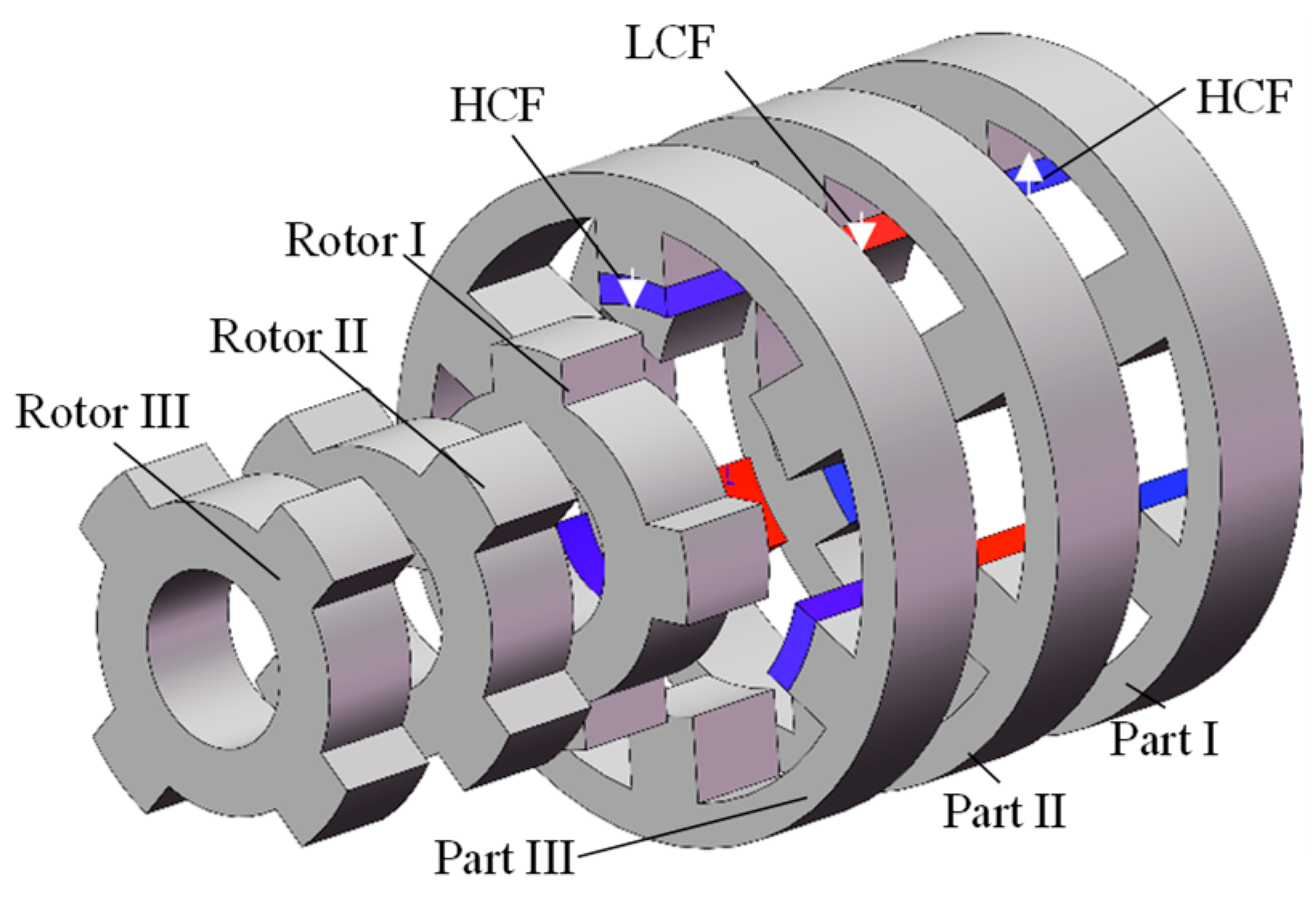
Figure 1 illustrates the topology of the proposed DCB-AXMM. As depicted, the machine adopts an axially segmented structure comprising three distinct sub-machines, denoted as Part I, Part II, and Part III. To ensure ease of manufacturing and modularity, all three parts share an identical stator/rotor pole combination, specifically 6 stator slots and 4 rotor poles (6s/4p). Regarding the excitation materials, the sub-machines differ in their permanent-magnet (PM) properties. Parts I and III utilize N42SH as high-coercive-force (HCF) PMs to provide the primary magnetic field. Conversely, Part II employs AlNiCo9 as the low-coercive-force (LCF) PM to enable the variable-flux memory function.
The magnetization direction and rotor alignment are designed to facilitate the specific flux-adjusting capability. The PMs in Part I and Part III are magnetized in opposite radial directions. Meanwhile, the PMs in Part II share the same magnetization polarity as those in Part III. In terms of rotor position, the rotors of Parts II and III are mechanically aligned with no offset. However, the rotor of Part I is shifted by a mechanical angle of 45° relative to the rotors of Parts II and III. Finally, integrated concentrated windings are wound around the stator teeth to perform both armature excitation and pulse magnetization functions.
2.2. Piecewise Linear Hysteresis Model of LCF PM
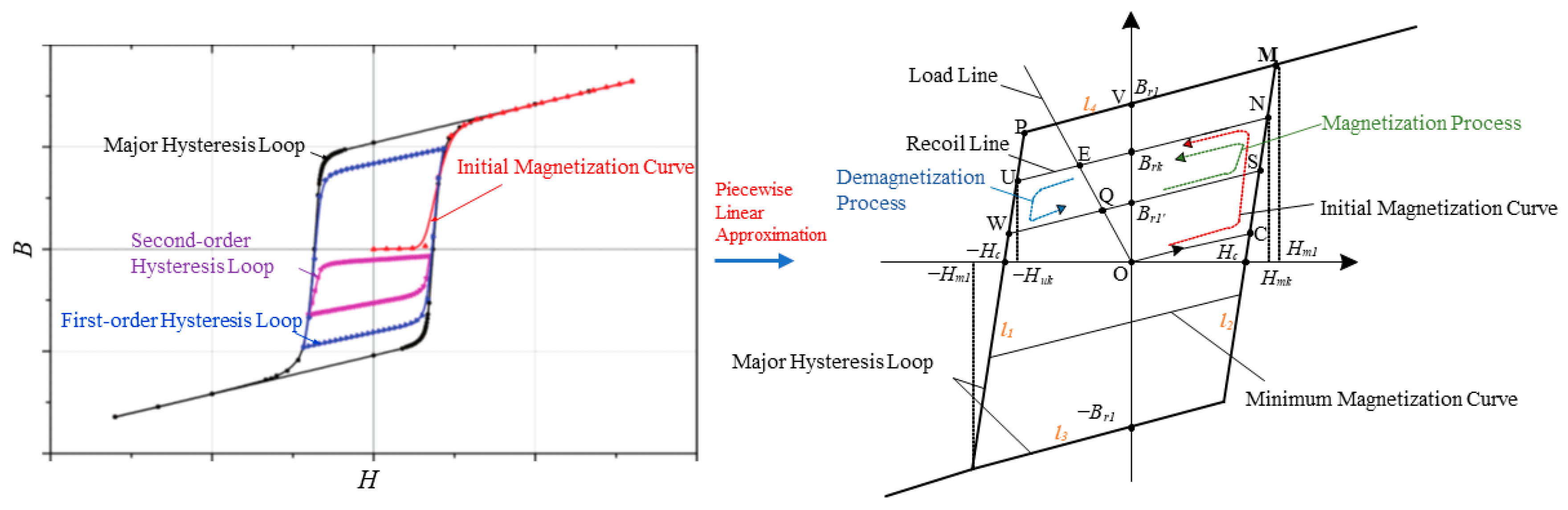
Based on the actual hysteresis loop data of the LCF permanent magnet provided in the manufacturer datasheet, an approximate hysteresis loop is derived, as shown in
Figure 2. The first-order hysteresis curve is defined as the curve that ascends or descends in the reverse direction originating from the major hysteresis loop. The second-order hysteresis curve originates from the first-order reversal curve, and by analogy,
nth-order hysteresis curves can be defined. As observed from the figure, the slope of the initial magnetization curve approximates that of the ascending branch of the major hysteresis loop, and the shapes of the minor loops resemble the envelope of the major hysteresis loop. Consequently, based on the aforementioned parallelogram characteristics, a hysteresis model for the LCF permanent magnet can be approximated through a reasonable piecewise linearization method. This simplified linear fitting algorithm incorporates the actual hysteresis characteristics of the LCF magnet while significantly reducing the computational complexity of the magnetic field analysis. The resulting simplified model is illustrated in
Figure 2. In the figure, the left and right segments (
l1 and
l2) of the major hysteresis loop can be expressed as:
The upper and lower segments (
l3 and
l4) of the recoil line are shown as follows:
In the formula, μr is the relative magnetic permeability of the low-coercivity permanent magnet; Brn is the remanence level corresponding to the n-th recoil line; Hc represents the LCF PM; and Hm denotes the magnetic field intensity at the vertex of the major hysteresis loop, i.e., the magnetic field intensity required for saturation magnetization (intrinsic coercivity).
By utilizing this hysteresis model, the sides of a translating parallelogram can be represented by simple linear equations, thereby facilitating a relatively simple simulation of the magnetization and demagnetization processes of low-coercivity permanent magnets.
In this model, the recoil lines consist of a set of parallel line segments, and the position of the new permanent-magnet operating point is determined by the applied magnetizing or demagnetizing pulsed magnetomotive force (MMF). Consequently, the process of determining the permanent-magnet operating point transforms into solving for the corresponding remanence on different recoil lines based on the applied pulsed MMF. The analysis of the motor magnetization process can be divided into three stages: initial magnetization, demagnetization, and remagnetization. Upon the completion of motor assembly, initial magnetization must be performed on the permanent magnets with low remanence capability. For the initial magnetization process, please refer to the
OCSN curve in the figure. During initial magnetization, when the initial magnetizing MMF (
H0) is less than the permanent-magnet coercivity (
Hc), the permanent magnet is considered not successfully magnetized and remains in an unmagnetized state; when
H0 is greater than the saturation magnetic field intensity (
Hm), the permanent magnet is considered to have achieved saturation magnetization; when
H0 lies between these two values, the operating point of each permanent-magnet unit must be solved based on the specific applied pulsed MMF to obtain the remanence
BrP corresponding to the different recoil lines. The remanence
BrP can be calculated using the following formula:
It can be observed from the figure that when a demagnetizing pulsed current is applied, the movement of the permanent magnet’s operating point can be represented by the polyline
EUWQ. The permanent magnet ultimately stabilizes at operating point Q. The remanence at this operating point is significantly reduced compared to E, thereby achieving the demagnetization operation. Similarly to the initial magnetization process described above, the remanence
Brl under demagnetization conditions can be expressed as
When a positive magnetizing pulsed current is applied, the generated magnetomotive force drives the operating point along
QSNE to return to the original operating point
E. The remanence is restored to its original level, thereby achieving the magnetization operation. Similarly, to the initial magnetization process described above, the remanence
Brl under magnetization conditions can be expressed as
2.3. Analysis of Flux Regulation Mechanism of Zero-Sequence Flux-Modulating Memory Machine
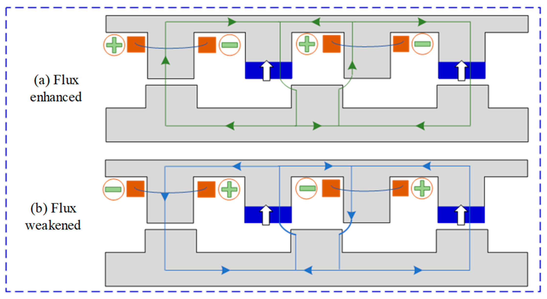
Figure 3 illustrates the flux regulation mechanism of the proposed stator permanent-magnet (PM) excitation zero-sequence flux-modulating memory machine. When a DC-bias current with the polarity indicated by the green “+ −” signs in
Figure 3a is injected into the three integrated windings, a magnetic flux path represented by the green lines in
Figure 3a is generated. This flux direction aligns with the magnetization direction of the LCF PM, thereby achieving the magnetization operation of the PMs.
Conversely, when a DC-bias current with the polarity indicated by the light blue “+ −” signs in
Figure 3b is applied, a magnetic flux path represented by the light blue lines in
Figure 3b is produced. This flux direction opposes the magnetization direction of the LCF PMs, thus realizing the demagnetization operation of the LCF PM.
To further demonstrate the flux regulation effect,
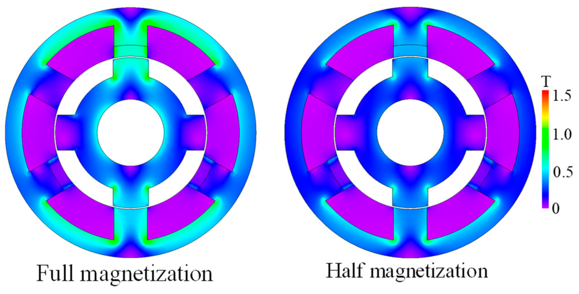
Figure 4 displays the magnetic flux density distribution (cloud map) of the motor under the full-magnetization and half-magnetization states. It can be observed from the figure that the flux density distribution undergoes significant changes.
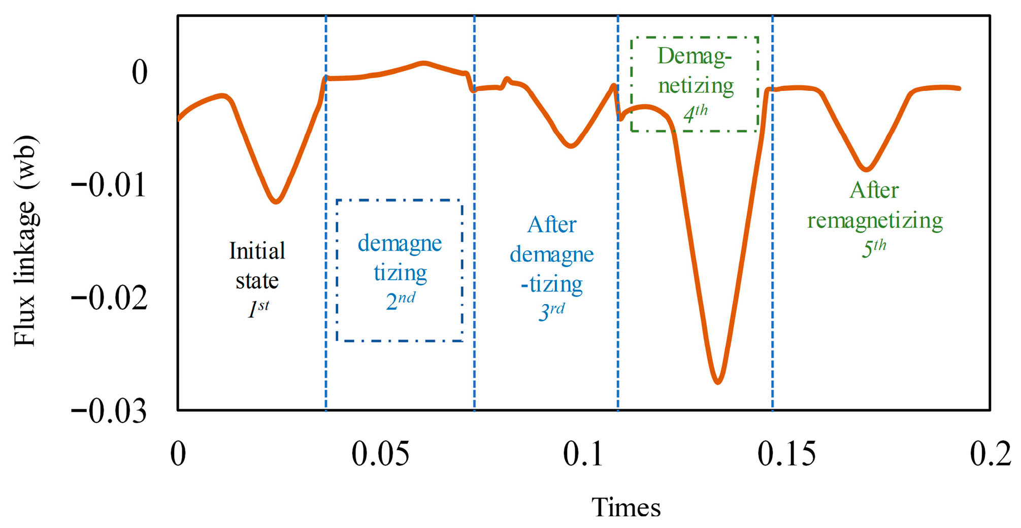
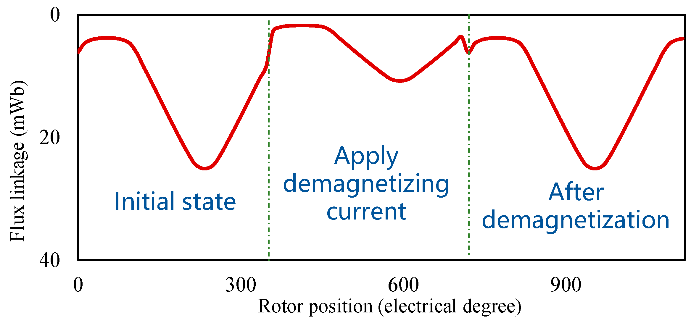
Moreover, the dynamic flux-linkage variations during the regulation process are depicted in
Figure 5. The first cycle represents the initial state of the motor. A field-weakening (demagnetizing) bias current is injected during the second cycle, and the resulting flux linkage after field weakening is shown in the third cycle. A magnetizing current is injected during the fourth cycle, and the flux linkage after magnetization is shown in the fifth cycle. The significant variation in the peak-to-peak value of the flux linkage indicates that the motor possesses excellent flux regulation capability.
2.4. Analytical Model for Sub-Machine (Part II)
The motor proposed in
Figure 1 is a six-stator-slot and four-rotor-pole (6S/4R) variable-reluctance memory motor with a doubly salient structure similar to a switched-reluctance motor. LCF PMs are embedded in three stator teeth, and a single-layer non-overlapping winding configuration is adopted. As shown in
Figure 3, this arrangement effectively reduces the risk of demagnetization of the permanent magnets and enables magnetization/demagnetization through a bias DC current. To further understand the operating principle of this type of motor and improve computational efficiency, this section conducts analytical modeling and analysis of the motor. The analytical model developed in this section is primarily intended to qualitatively explain the machine’s basic operating principles and variable-reluctance mechanism. Accordingly, to ensure rigorous and credible results, all subsequent parameter optimizations and performance evaluations are conducted using non-linear finite element analysis (FEA), which incorporates the effects of core saturation and complex magnetic interactions.
To simplify the analysis process, the following assumptions are made in this section: (1) the permeability of the iron poles is infinitely large, and the iron core saturation and leakage flux are neglected; (2) magnetic flux lines are perpendicular to the surfaces of the stator and rotor cores; (3) end effects are ignored, and the analysis model is treated as a two-dimensional (2D) modeling problem [
27,
28,
29,
30,
31,
32].
The MMF can be expressed as
where the
m is the order of the MMF harmonic of the LCF PM;
Ns is the number of stator teeth;
βs and
βr are the slot opening ratios of the stator and rotor, respectively;
θ is the relative position between the stator teeth and rotor teeth;
hm is thickness of the LCF PM;
gair is the length of air gap.
The simple air-gap permeance can be expressed as
The air-gap flux density can be derived by
The flux-linkage expression of the motor is
where
represents the air-gap radius, and
represents the axial length of the motor core.
The back-EMF can be expressed as
The torque can be expressed as
In the formula,
Imax is the peak current of the motor.
Pi can be understood as the pole pairs of the motor armature winding. In order to form a three-phase winding, the pole pairs of the stator winding and the number of stator slots must satisfy the following condition:
From Formula (15), it can be seen that to obtain the maximum torque, the minimum armature winding pole pairs are generally selected.
2.5. Working Principle of the DCB-AXMM
Because the proposed machine has three sub-machines, the back-EMF and the electromagnetic torque of DCB-AXMM (
Ef and
Tf) can be expressed as
where the
EPI,
EPII and
EPIII are the back-EMF values of the Part I, Part II and Part III sub-machines, respectively.
TPI,
TPII and
TPIII are the electromagnetic torque values of the Part I, Part II and Part III sub-machines, respectively. Due to the fact that the design parameters are the same for the Part I and Part III sub-machines, the harmonic content of back-EMF can be decreased based on the even harmonic elimination methods proposed in [
25]. The Part I and Part III sub-machines provide key contributions for electromagnetic performance, and the Part II sub-machine provides the flux-adjustment capability.
3. Two-Step Optimization Method
Optimizing the design parameters is critical for electromagnetic performance. However, due to the machine’s complex structure—characterized by variations across three axial segments—standard global optimization techniques are often computationally expensive or ineffective. To address this geometric complexity, a hierarchical two-stage optimization framework is introduced.
Stage 1: Cross-sectional optimization: The first stage focuses on the 2D optimization of the sub-motors. This process isolates and refines major geometric variables, including stator tooth width, permanent-magnet (PM) thickness, and rotor tooth width, to establish a high-performance cross-sectional design.
Stage 2: Axial dimension sizing: The second stage builds upon the optimized cross-sectional parameters determined in the first step. It specifically targets the 3D domain by optimizing the axial length of each sub-motor to derive the optimal axial length ratio between the segments.
By decoupling the cross-sectional design from the axial sizing, this stepwise methodology effectively navigates the high-dimensional design space, ensuring that the final motor parameters yield the best possible performance.
3.1. First Optimization Step
The first step of the optimization framework utilizes a genetic algorithm-based multi-objective approach, specifically targeting the unit motor (Part I) rather than the full machine assembly. Performing a global optimization on the complete three-dimensional (3D) topology is impractical due to the high computational cost of 3D finite element analysis (FEA), which would result in prohibitive simulation times and delay the design iteration process.
Furthermore, the structural topology of the motor facilitates a simplified approach. Since the machine employs an integrated winding configuration that passes through all three axial segments, maintaining a consistent stator slot shape is essential to guarantee a high slot-fill factor and simplify manufacturing. Consequently, the three axial stators are constrained to have identical radial dimensions (such as tooth width and slot shape), varying only in their axial lengths and the grade of PM material used.
This geometric constraint allows the optimization problem to be mathematically decoupled: the complex 3D problem is transformed into a manageable 2D sub-motor optimization. By reducing the dimensionality of the simulation model, the computational efficiency is significantly enhanced, allowing the genetic algorithm to converge on the optimal stator and rotor parameters rapidly.
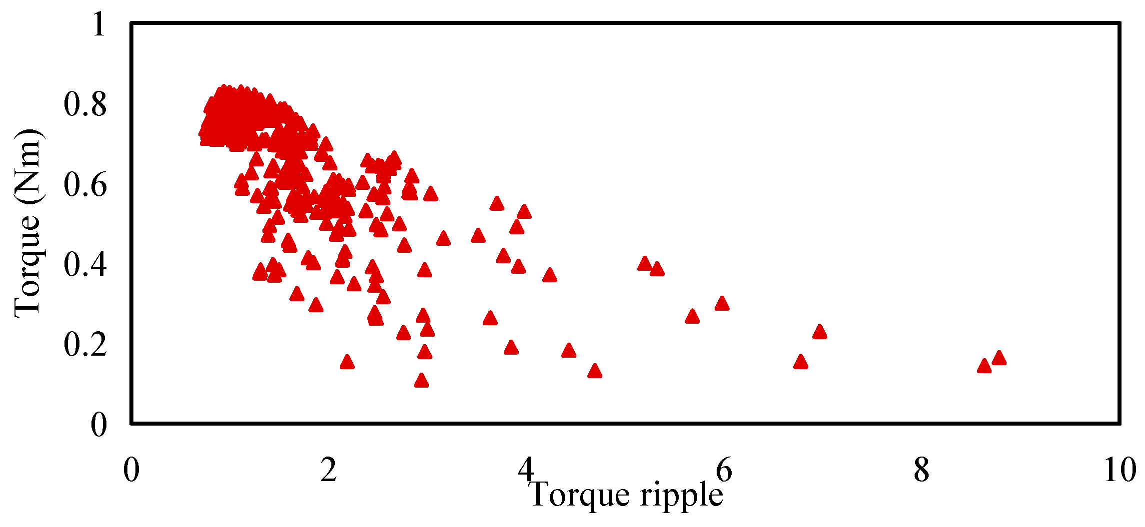
To ensure the reproducibility of the optimization process, the detailed setup for the genetic algorithm (GA) is explicitly defined. The primary goal of the cross-sectional optimization is to maximize the torque output while maintaining a smooth operation. Therefore, the multi-objective functions are mathematically formulated to maximize the average electromagnetic torque (
Tavg) and minimize the torque ripple (
Tripple) under the FM state. Additionally, the current density is set to 5.5 A/mm
2. The outer stator radius and air-gap length are set to 45 mm and 0.5 mm. The combination of stator slot and rotor pole is constant. The specific configuration parameters for the GA are detailed as follows: population size: 22; maximum number of generations: 35. The Pareto front solutions obtained from this multi-objective optimization are presented in
Figure 6. The plot illustrates the trade-off relationship between the average torque and the torque ripple, providing a basis for selecting the optimal 2D cross-sectional parameters.
3.2. Second Optimization Step
Based on the first step of optimization, the dimensions such as stator tooth width, stator tooth length, rotor tooth width, rotor tooth length, PM width, and length of the motor have been determined. For the second optimization step, the parameters are transformed from a comprehensive 3D optimization into a purely axial ratio for the motor, thereby enhancing the efficiency of the optimization process.
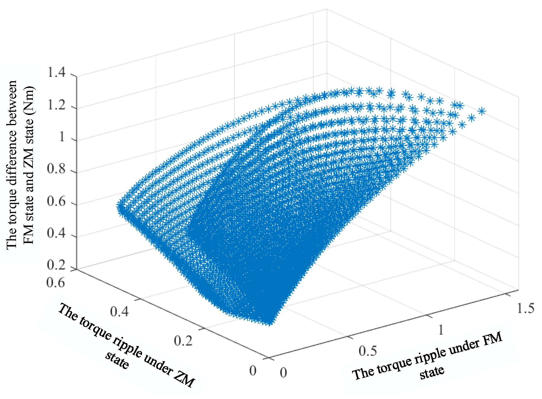
In the second step of optimization, two operating states of the motor are defined: the fully magnetized (FM) state and the zero-magnetization (ZM) state. The average torque and torque ripple of the motor can be calculated under various axial ratios and magnetization states. The difference between the average torque under different magnetization states is taken as the
z-axis value, the torque ripple in the FM state as the
x-axis value, and the torque ripple in the ZM state as the
y-axis value. The scatter plot formed by multiple sets of data is shown in
Figure 7.
Based on the data presented in
Figure 7, the selection criterion is that the ratio of the torque difference to the average torque in the FM state exceeds 20%, supplemented by the additional condition that both the torque ripple in the FM state and that in the ZM state are below 30%. Ultimately, the optimal ratio selected is 4.5:3.6:1.9 (axial length of Part I, axial length of Part II, and axial length of Part III). The optimal design parameters are shown in
Table 1.
4. Electromagnetic Performances
4.1. Air-Gap Flux Density
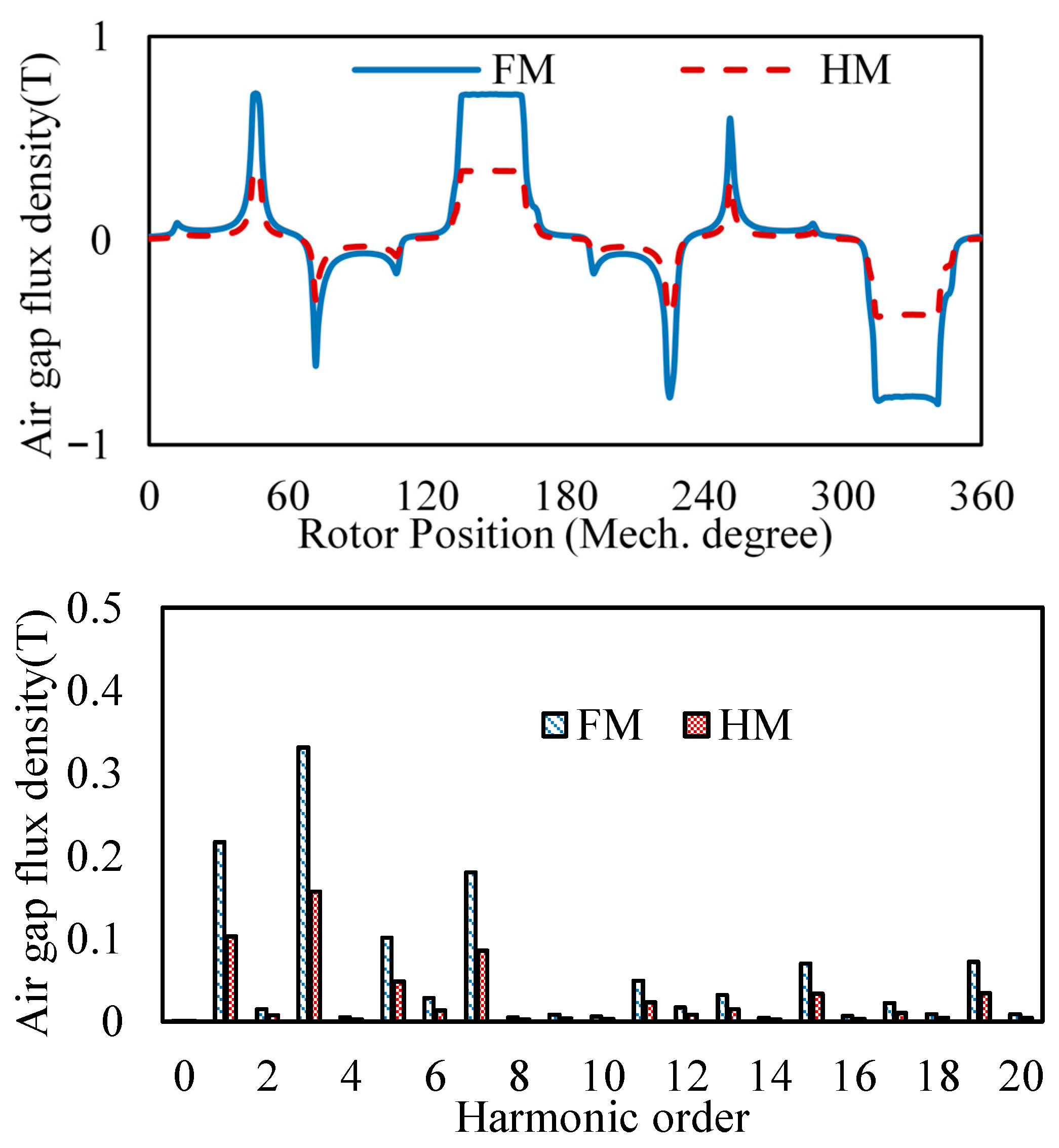
In order to show the flux-adjustment capability, the air-gap flux density of the Part II sub-machine is analyzed since it houses the LCF PMs. The magnetization levels of the LCF PM are divided into three types, i.e., FM state, half-magnetization (HM) state and zero-magnetization (ZM) state, to facilitate description.
Figure 8 shows the no-load air-gap flux density waveforms at the FM and HM levels. It can be seen that there are significant changes in fundamental amplitude between the FM and HM levels, which proves that the machine has good flux regulation ability.
4.2. No-Load Back-EMF
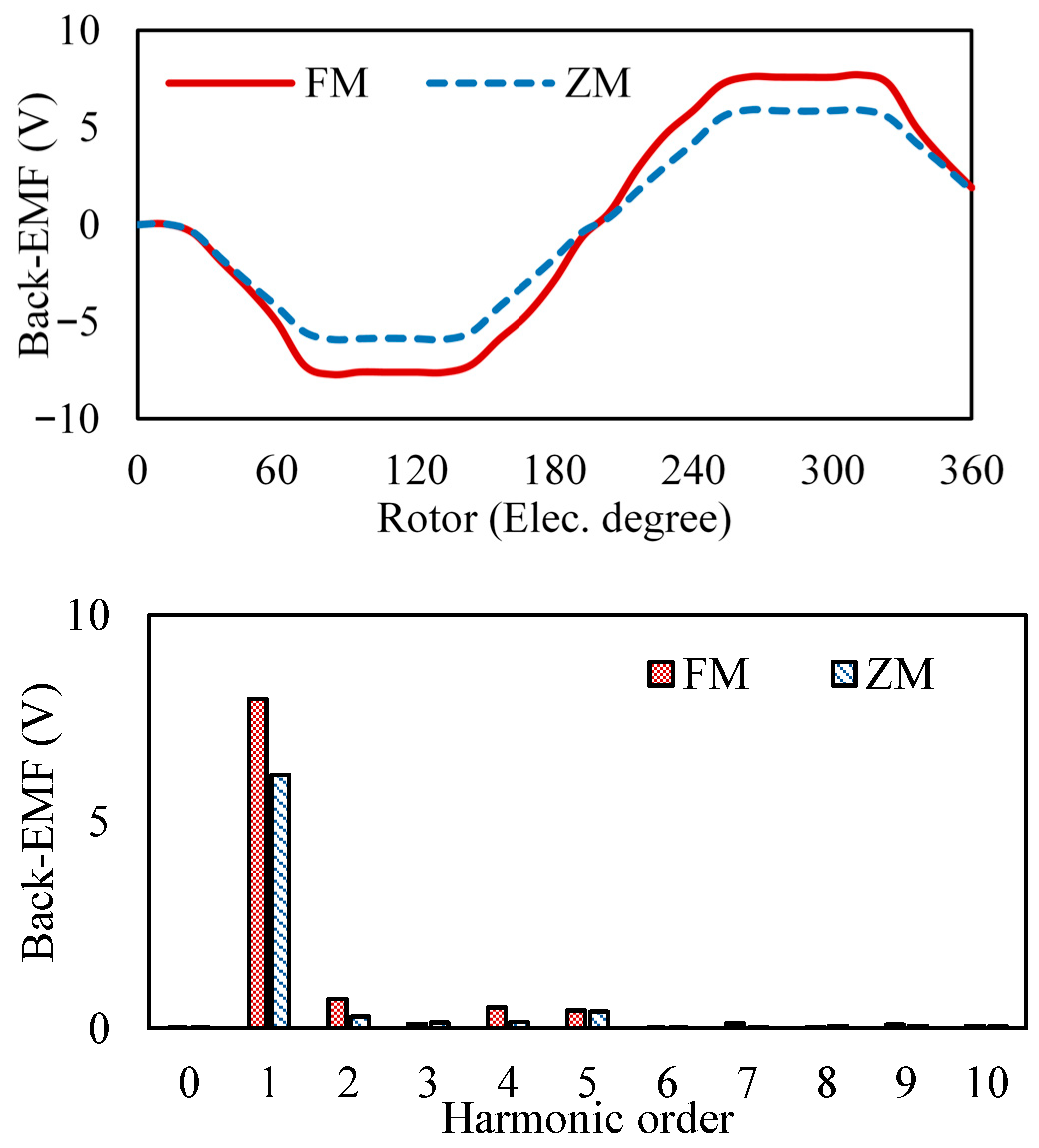
Figure 9 shows the no-load EMF waveforms at the FM and ZM levels. It can be seen that the total harmonic distortions (THD) of back-EMF in the different magnetization levels are 7.7% and 9.4%, respectively. The ZM has a relatively low THD due to the even harmonic elimination methods proposed in [
25]. It demonstrates that the proposed machine possesses good magnetic adjustability.
4.3. Electromagnetic Torque
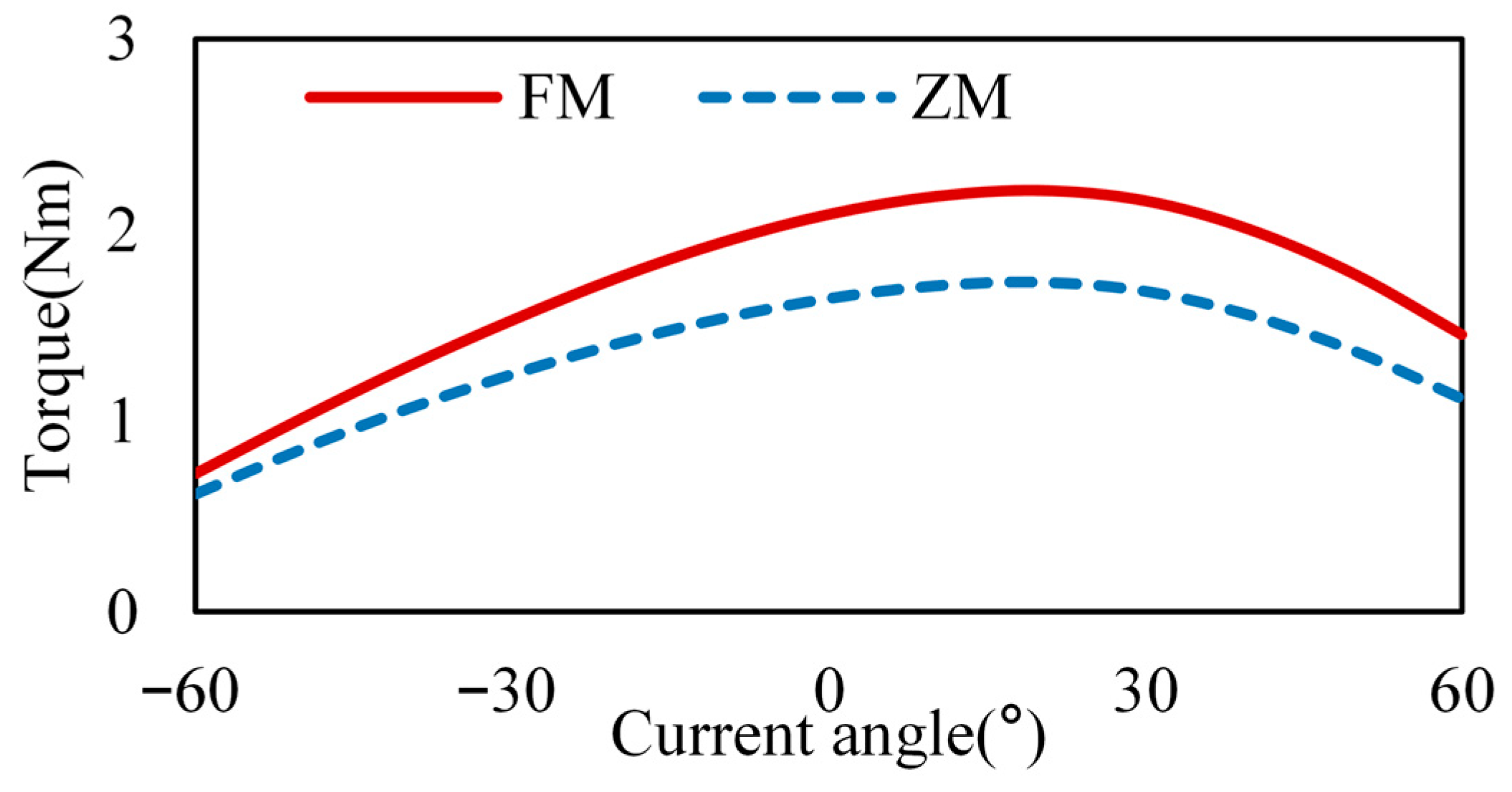
Figure 10 shows the curve of the torque versus the current angle, ranging from a current angle of −60° to 60° with a 10° interval. It reveals that the maximum torque of the motor occurs at an electrical angle of 20°. This observation indicates that the motor designed in this section exhibits a saliency ratio.
Based on the current angle (20°) obtained from
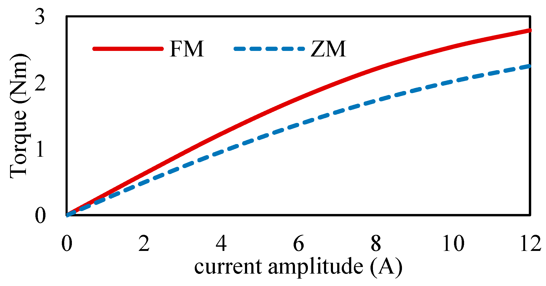
Figure 10, the relationship between current and motor torque is calculated and shown in
Figure 11. It can be observed that the proposed machine exhibits a nearly linear relationship within the current amplitude range of 0–8 A, indicating that the stator and rotor of the motor are exhibiting unsaturation magnetization. However, the torque of the motor exhibits non-linearity when the current amplitude is larger than 8 A, suggesting that the magnetic flux density of the stator and rotor has entered a state of saturation.
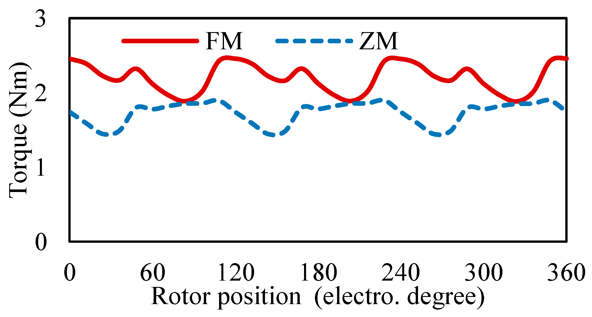
The electromagnetic torque waveforms under different magnetization states are shown in
Figure 12. It can be seen that the average torques in FM and ZM states are 2.2 Nm and 1.72 Nm, respectively, with a difference close to 0.5 Nm and a torque reduction exceeding 20%. This indicates that the motor torque can be varied and possesses wide-ranging torque output adjustment. Additionally, the torque ripples under different magnetization states were analyzed, yielding values of 26.2% and 26.1%, respectively. This demonstrates a relatively stable quality of motor torque output under different magnetization states.
4.4. The Capability of Overload
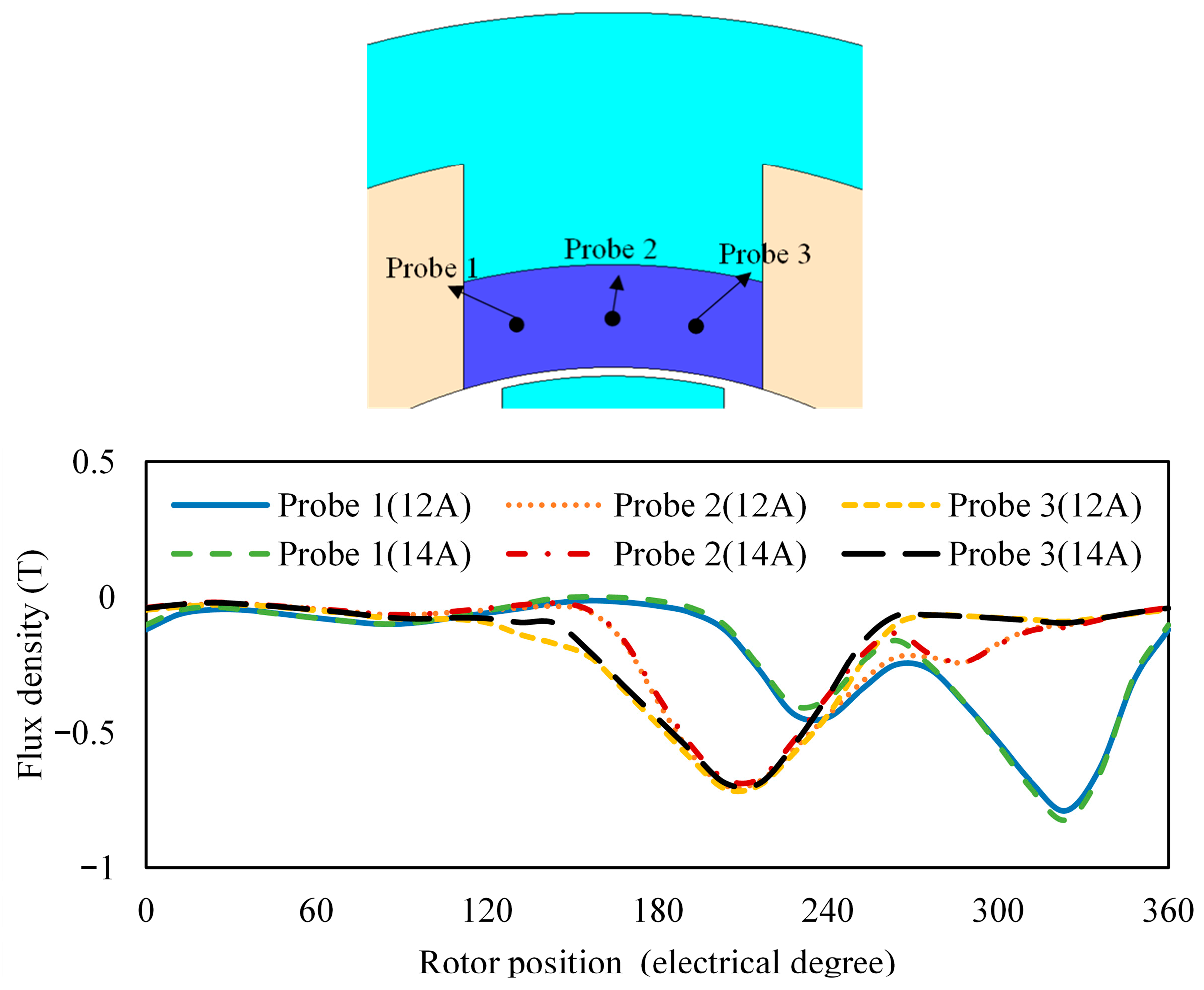
LCF PMs exhibit a relatively low coercivity and are influenced by armature currents. Thus, it is imperative to analyze the operating points of LCF PMs under various armature currents to determine the maximum overload current for the motor. To comprehensively evaluate the demagnetization risk, three sensing points (Probe 1, Probe 2, and Probe 3) are symmetrically defined at the edges and the center of the LCF PM to monitor the local operating points. The analysis of operating points for LCF PMs under different currents is illustrated in
Figure 13. It reveals that when the motor current exceeds an amplitude of 14 A, the operating point at sensing point 1 of the LCF PMs undergoes a change in magnetization direction in the electrical cycle, indicating that the magnet cannot work stably under the conditions. In contrast, the operating point at an amplitude of 12 A can maintain its direction. Therefore, the machine has 1.5-times overload capacity.
4.5. Operating Point Analysis of HCF PMs and LCF PMs Under Magnetization/Demagnetization Working Conditions
Given that the proposed machine is a memory motor, there are also magnetization and demagnetization conditions that need to be taken into account. Therefore, it is necessary to analyze the stability of HCF PMs under magnetization/demagnetization working conditions.
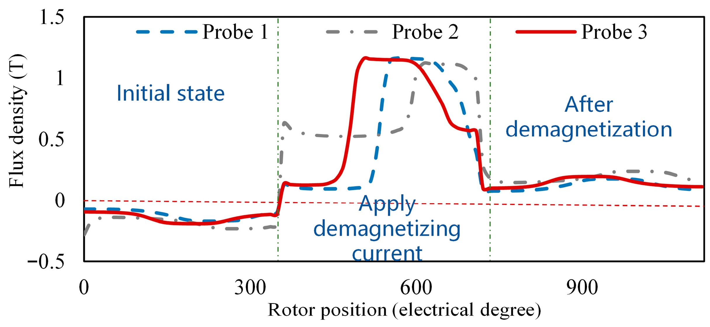
This section sets the demagnetizing current to 15 A. The operating point changes of the LCF PMs for the Part II sub-motor are presented in
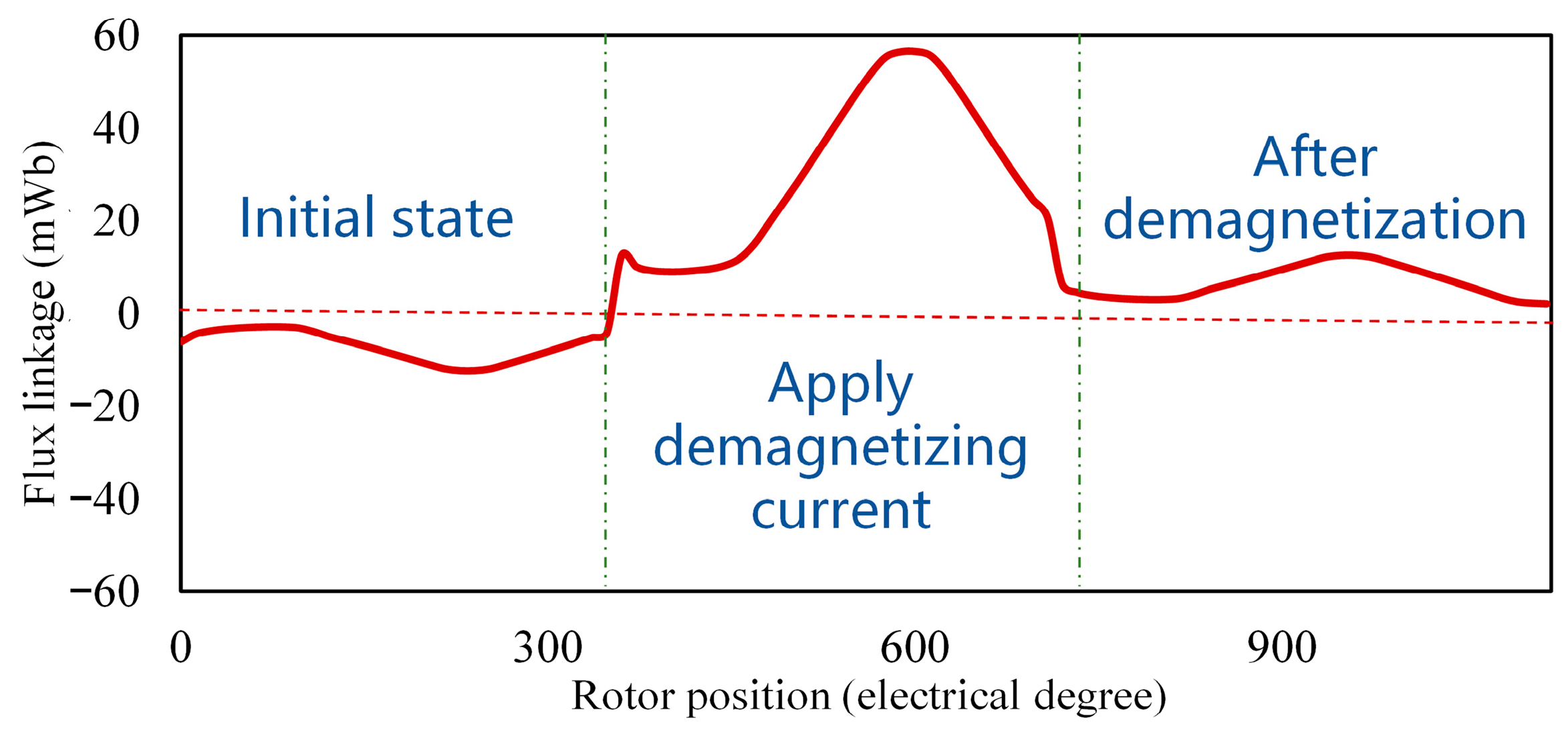
Figure 14. It reveals that the magnetization direction of LCF PM shifts from negative to positive, indicating that the direction of the LCF PM changes after demagnetization. This is reflected in the flux linkage of the motor, as shown in
Figure 15. It illustrates that the originally negative unipolar flux linkage changes to a positive unipolar flux linkage, indirectly indicating a change in the polarity or magnetization direction of LCF PM. The results presented in
Figure 14 and
Figure 15 demonstrate that the motor, under a demagnetizing current of 15 A, has surpassed the demagnetized state, which would not occur under normal operating conditions. Therefore, using this current to analyze HCF PMs is persuasive.
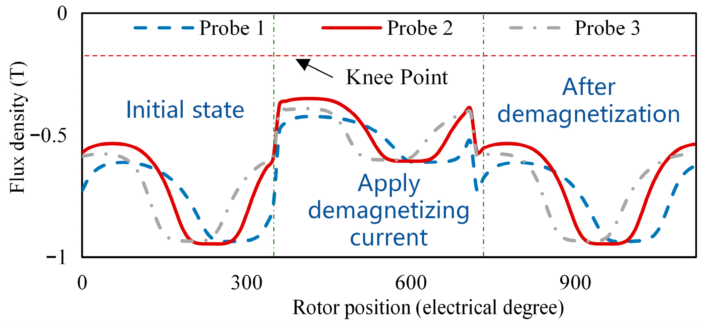
To analyze extreme conditions, the operating temperature of the HCF PM is set at 100 °C under the demagnetizing current of 15 A. If the HCF PMs can still maintain stability under this extreme condition, it indicates that the motor will definitely remain stable under normal operating conditions. Under the extreme operating condition, the analysis of the operating points and the flux-linkage changes in the Part I sub-motor before and after magnetization and demagnetization are shown in
Figure 16 and
Figure 17, respectively. It can be observed that there is no change in the operating points and the sub-motor’s flux linkage. Therefore, it demonstrates that the designed motor possesses stability.
4.6. Numerical Validation and Sensitivity Analysis
Given the complex axial parallel topology of the DCB-AXMM, and prior to future experimental prototyping, comprehensive numerical validations are conducted to ensure the credibility of the FEA results.
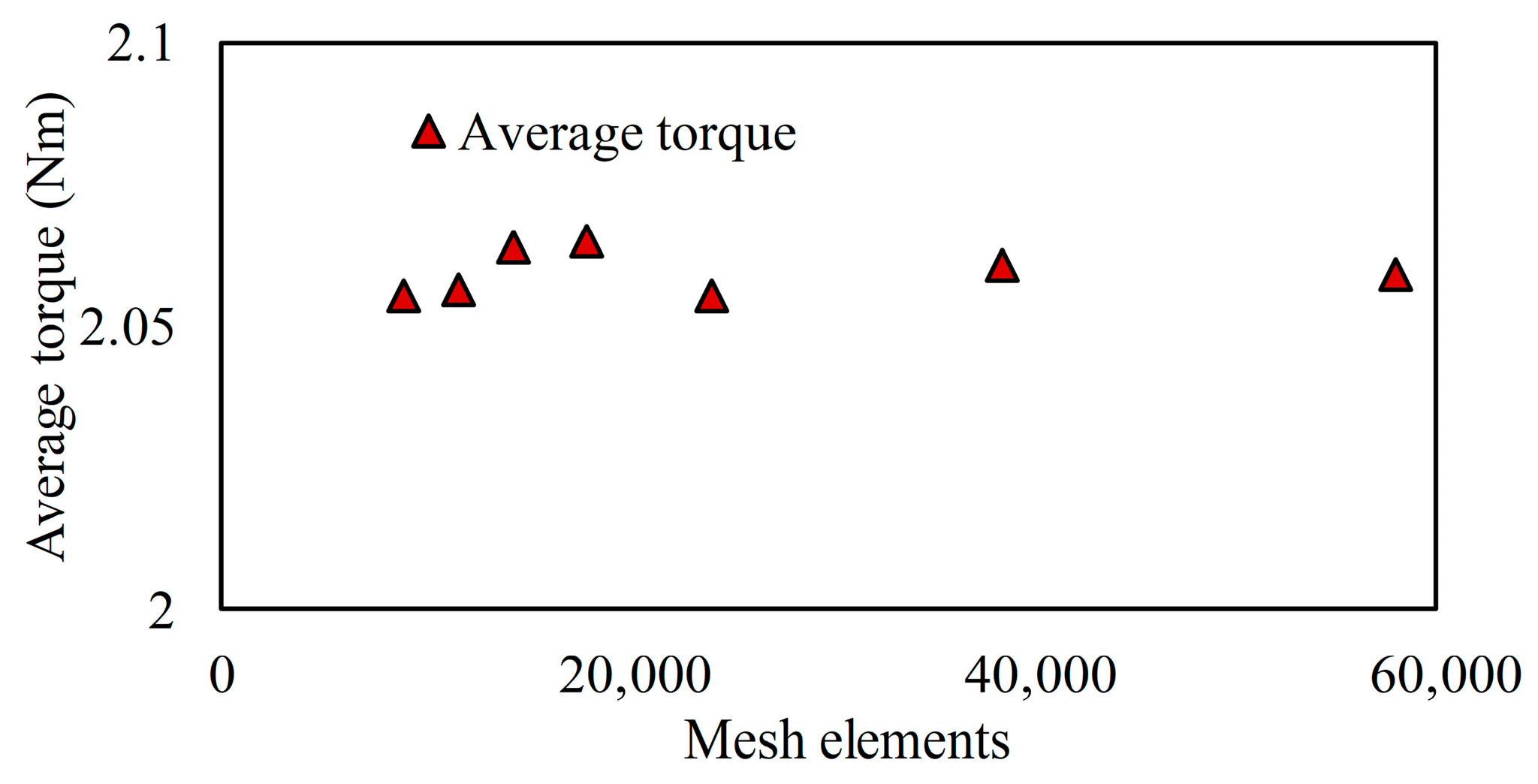
To eliminate computation errors caused by mesh discretization, a mesh independence study was performed. As shown in
Figure 18, the average electromagnetic torque under the FM state was monitored as the number of mesh elements increased from 9000 to 60,000. The variation in the average torque stabilized to within 0.5%. Consequently, the mesh density corresponding to 20,000 elements was selected for simulations in this study, striking an optimal balance between computational accuracy and time cost.
- B.
Sensitivity to Manufacturing Tolerances
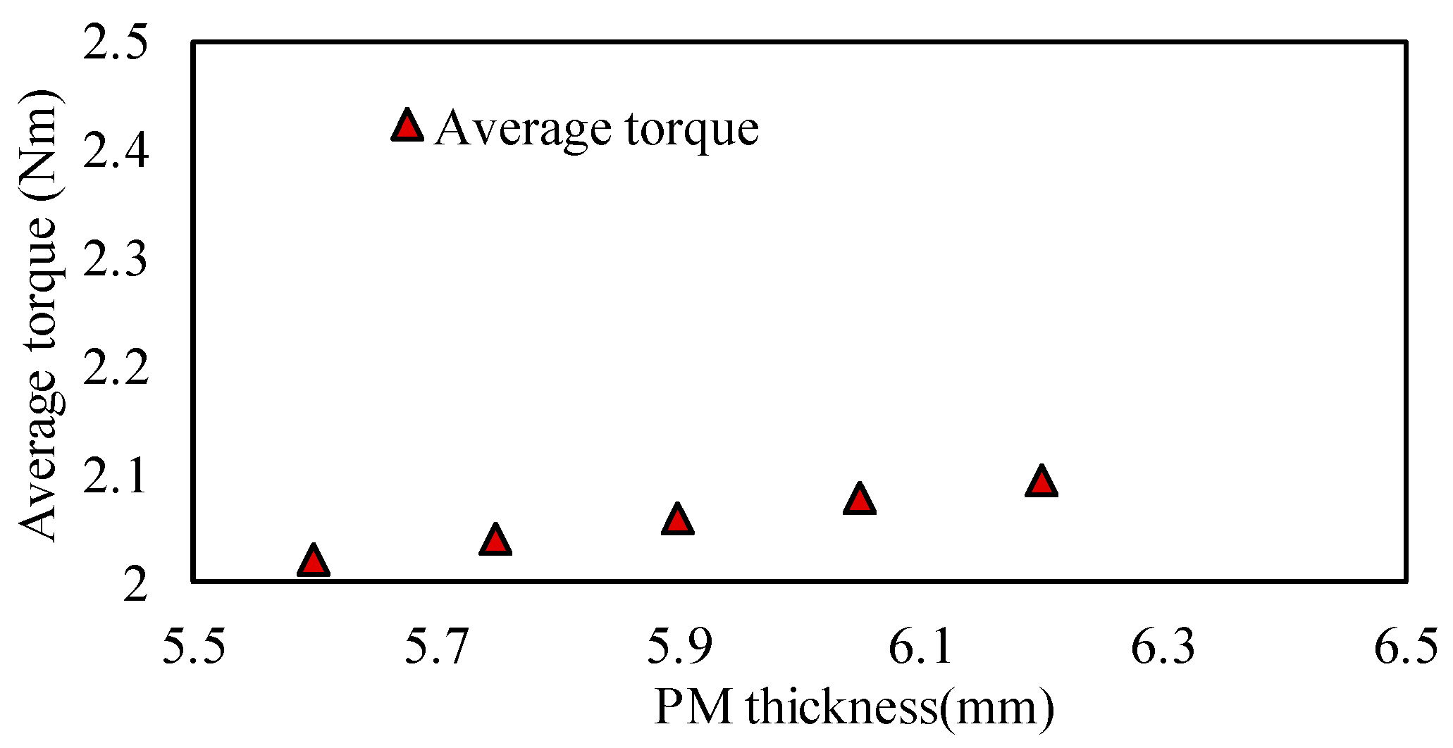
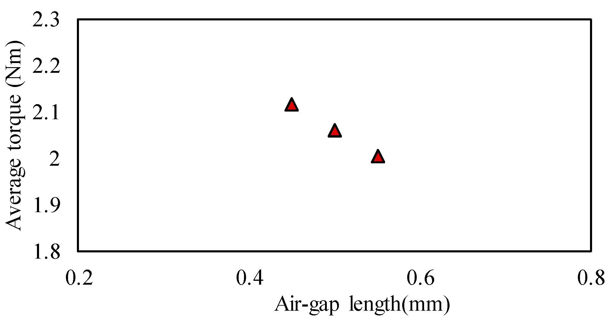
Given the dual-PM topology of the proposed machine, a sensitivity analysis was conducted on two critical manufacturing parameters: the air-gap length and the thickness of the PM. A ±10% variation for the air-gap length and the ±0.3 mm/±0.15 mm variation for the thickness of the PM were evaluated and their impact on the average torque under the FM state was observed (as shown in
Figure 19 and
Figure 20). The FEA results demonstrate that a 10% variation in the air-gap length causes a minor torque variation of less than 3%. Similarly, the ±0.3 mm/±0.15 mm manufacturing tolerance in the thickness of the PM causes only a minor torque variation of less than 2%. These results verify that the proposed DCB-AXMM exhibits robust electromagnetic performance within standard manufacturing tolerance ranges.
4.7. Magnetic Regulation Capability Analysis
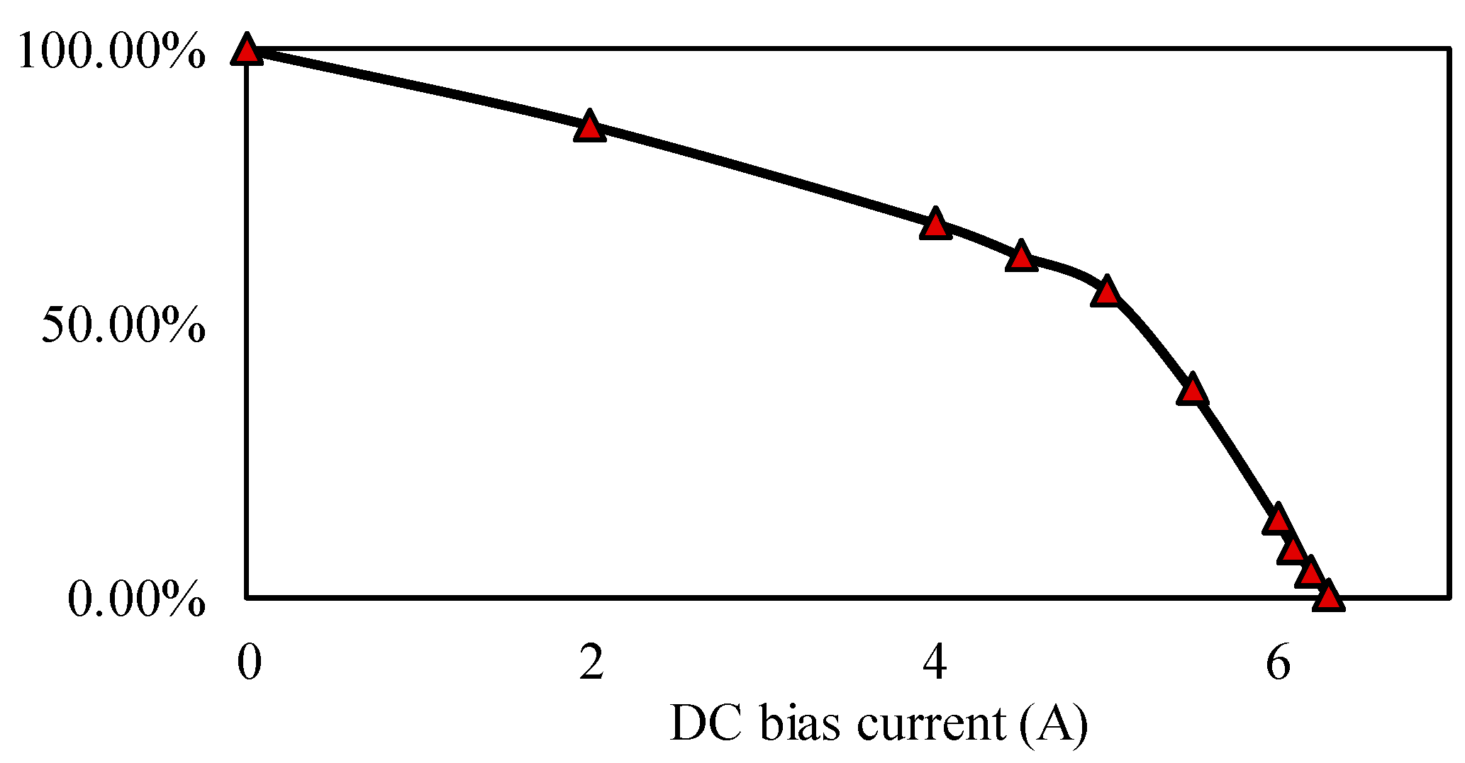
To establish a clear quantitative relationship between the DC-bias current and the magnetization state, a detailed sweep analysis was performed based on the Part II sub-machine. Given that the no-load back-EMF amplitude is directly proportional to the air-gap flux and the remanence of the LCF PMs, the back-EMF amplitude at the FM state is defined as the 100% baseline. By applying various DC-bias currents, the corresponding back-EMF amplitudes were recorded and calculated as percentages of the FM baseline.
As illustrated in
Figure 21, this percentage curve effectively represents the dynamic continuous variation in the LCF PMs remanence. The quantitative results demonstrate a clear mapping: a bias current of approximately 5 A transitions the LCF PMs to the HM state (approximately 50% remanence), while a current of around 6.2 A is required to fully demagnetize the Part II sub-machine, reaching the approximately ZM state (approximately 0% remanence). This continuous quantitative relationship provides a reference for the flexible flux regulation control of the proposed DCB-AXMM.
4.8. Performance Comparison Between MW-AXMM and DCB-AXMM
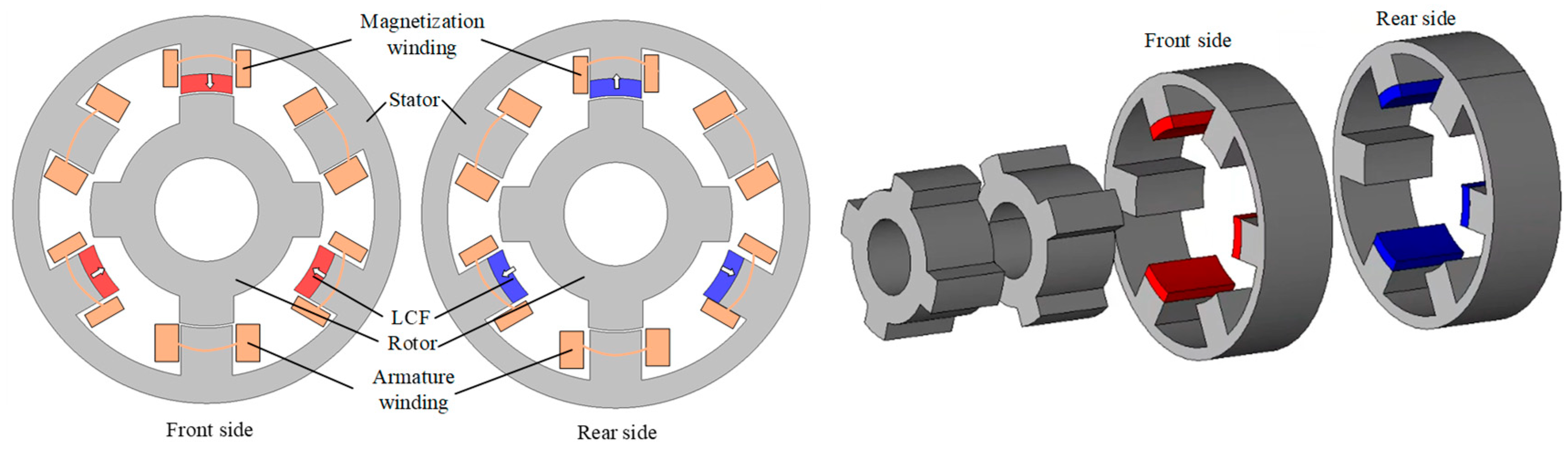
An axial parallel memory machine with magnetization windings (MW-AXMM) is introduced for performance comparison with the proposed machine. As shown in
Figure 22, the MW-AXMM has identical axial stator length and outer dimensions to the proposed DCB-AXMM. The front and rear sub-machines are equipped with LCF PMs configured with opposite magnetization directions as MW-AXMM. To regulate LCF remanence, independent magnetization windings are configured for each sub-machine. Consequently, the magnetization windings and armature windings share the same stator slots. Because the magnetization windings remain inactive during normal operation, this configuration decreases the spatial utilization rate of the stator slots, limiting the electrical performance.
The electromagnetic performance of both machines is evaluated under the FM state.
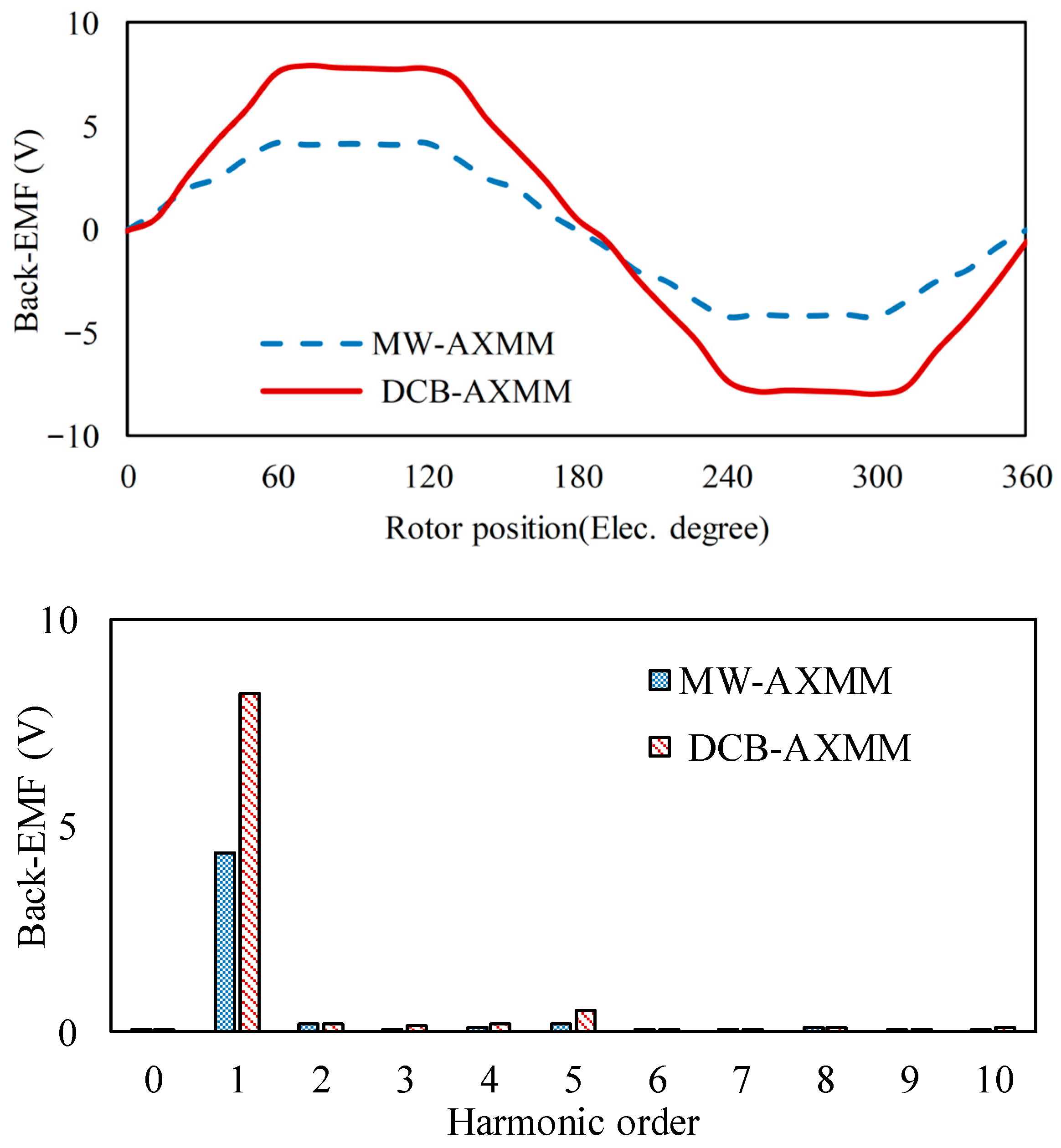
Figure 23 illustrates the no-load back-EMF waveforms and their corresponding harmonic spectra for both machines. As shown in
Figure 23, the fundamental amplitude of the back-EMF in the proposed DCB-AXMM reaches approximately 8.2 V, which is significantly higher than the 4.3 V achieved by the MW-AXMM.
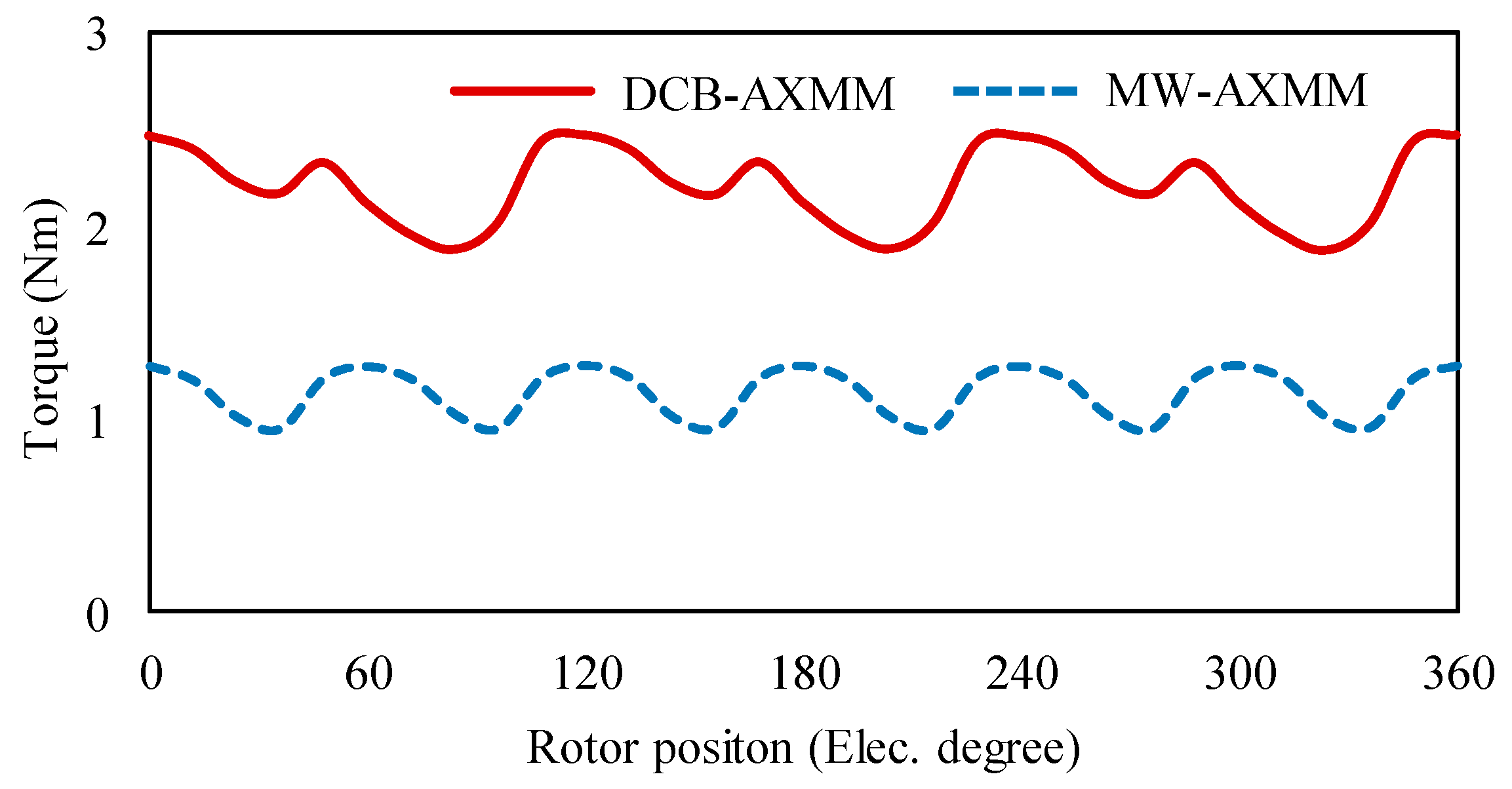
Furthermore, the torque performance comparison is presented in
Figure 24. The proposed DCB-AXMM outputs an average electromagnetic torque of approximately 2.2 Nm. The average torque of the MW-AXMM is only about 1.1 Nm under the same operating conditions. These results verify that the proposed DCB-AXMM topology effectively resolves the spatial conflict between armature and magnetization coils, achieving a quantitative improvement in torque density.
5. Conclusions
The paper proposes the DCB-AXMM. Its detailed machine topology and working principle are elaborated, followed by an investigation and analysis of the corresponding electromagnetic performance. Results show that the DCB-AXMM exhibits excellent flux regulation capability. Based on the aforementioned analysis, the proposed machine features the following characteristics:
a. Parts I and III of the DCB-AXMM share the same main dimensions, with the key differences being the opposite magnetization directions of their respective HCF PMs and distinct axial lengths.
b. The LCF PMs in Part II enable flexible magnetic adjustment. Meanwhile, due to the stable operating points of the HCF PMs, they remain nearly unaffected during the magnetization and demagnetization processes, effectively addressing the problem of non-uniform magnetization. Benefiting from the spatial isolation of the excitation sources, the LCF PMs are effectively shielded from HCF PM interference and armature reaction, granting the proposed machine a robust 1.5-times overload capability.
c. The motor adopts a hybrid permanent-magnet design: HCF PMs provide the main magnetic flux, ensuring the motor retains a relatively stable torque output; LCF PMs allow for flexible flux adjustment, thereby achieving a balance between flux regulation capability and enhanced torque density. The machine transitions between full-, half-, and zero-magnetization states, achieving a 21.8% reduction in average electromagnetic torque (from 2.2 Nm to 1.72 Nm).
d. The axially segmented structure can effectively mitigate the influence of HCF PMs on LCF PMs. Thus, this configuration can reliably preserve the stability of the LCF PMs’ operating points under various working conditions.
Author Contributions
Conceptualization, L.Q., Y.S. and Y.Z.; methodology, L.Q.; validation, Y.Z., Y.S. and L.Q.; formal analysis, L.Q.; investigation, Y.Z.; writing—original draft preparation, Y.Z. and Y.S.; writing—review and editing, Y.Z. and Y.S.; visualization, Y.Z. and L.Q. All authors have read and agreed to the published version of the manuscript.
Funding
This work was jointly supported in part by the National Key R&D Program of China (Grant No.: 2024YFB2505200); supported in part by Jiangsu Provincial Frontier Technology R&D Program under Grant BF2024064; supported in part by National Natural Science Foundation of China under Grant 52275009 and Grant 52207038; supported in part by Shanghai AI-Driven Program for Promoting the Reform of Research Paradigms and Empowering Disciplinary Leapfrog Development; and supported in part by “Research and Demonstration of Key Technologies for Smart Water Supply and Green Operation in Lingang New Area (Research on Key Technologies of Zero-Carbon Buildings)”.
Data Availability Statement
The original contributions presented in this study are included in the article. Further inquiries can be directed to the corresponding author.
Conflicts of Interest
Authors Yanwen Zheng and Yuanyuan Shan were employed by the company Wolong Electric Drive Group Co., Ltd. The remaining authors declare that the research was conducted in the absence of any commercial or financial relationships that could be construed as a potential conflict of interest.
Acronyms
| MM | Memory Machine |
| PM | Permanent Magnet |
| LCF | Low Coercive Force |
| HCF | High Coercive Force |
| FEA | Finite Element Analysis |
| FM | Full Magnetization |
| EMF | Electromotive Force (Back-EMF) |
| DCB-AXMM | Axial Parallel Memory Machine with DC-bias Flux-Adjustment Capability |
| MS | Magnetization State |
| MMF | Magnetomotive Force |
| GA | Genetic Algorithm |
| HM | Half Magnetization |
| ZM | Zero Magnetization |
| THD | Total Harmonic Distortion |
| 2D/3D | Two-Dimensional/Three-Dimensional |
References
- Hao, W.; Zhang, G.; Liu, W.; Liu, H.; Wang, Y. Methods for reducing cogging force in permanent magnet machines: A review. Energies 2023, 16, 422. [Google Scholar] [CrossRef]
- Yu, C.; Chau, K.T. Dual-mode operation of DC-excited memory motors under flux regulation. IEEE Trans. Ind. Appl. 2011, 47, 2031–2041. [Google Scholar] [CrossRef]
- Arribas, B.; Almandoz, G.; Egea, A.; Madina, P.; Iturbe, I. Adoption of multiphase and variable flux motors in automotive applications. Appl. Sci. 2024, 14, 10932. [Google Scholar] [CrossRef]
- Yu, C.; Chau, K.T. Design, analysis, and control of DC-excited memory motors. IEEE Trans. Energy Convers. 2011, 26, 479–489. [Google Scholar] [CrossRef]
- Chen, H.; Du, Y.; Xiao, F.; He, Z. A pole-changing double-sided excitation permanent magnet vernier motor for electric tractors. Electronics 2026, 15, 324. [Google Scholar] [CrossRef]
- Li, F.; Chau, K.T.; Liu, C.; Qiu, C. New approach for pole-changing with dual-memory machine. IEEE Trans. Appl. Supercond. 2014, 24, 0501504. [Google Scholar]
- Liu, Y.; Zhang, X.; Niu, S.; Fu, W.; Guo, X. Design and analysis of a linear memory machine for ocean wave power generation. Energies 2020, 13, 5216. [Google Scholar] [CrossRef]
- Wu, J.; Zhu, X.; Xu, L.; Quan, L.; Fan, D.; Yang, J. Optimization design of a flux memory motor based on a new non-linear MCDRN model. IET Electr. Power Appl. 2019, 13, 2035–2043. [Google Scholar] [CrossRef]
- Yang, H.; Lin, H.; Zhu, Z.Q.; Fang, S.; Huang, Y. Novel flux-regulatable dual-magnet vernier memory machines for electric vehicle propulsion. IEEE Trans. Appl. Supercond. 2014, 24, 0601205. [Google Scholar]
- Yang, H.; Lin, H.; Zhu, Z.Q.; Lyu, S. Novel variable reluctance hybrid magnet memory machines. In 2017 20th International Conference on Electrical Machines and Systems (ICEMS); IEEE: Piscataway, NJ, USA, 2017; pp. 1–6. [Google Scholar]
- Yang, H.; Zhu, Z.Q.; Lin, H.; Xu, P.; Zhan, H.; Fang, S.; Huang, Y. Design synthesis of switched flux hybrid-permanent magnet memory machines. IEEE Trans. Energy Convers. 2017, 32, 65–79. [Google Scholar] [CrossRef]
- Yang, H.; Zhu, Z.Q.; Lin, H.; Wu, D.; Hua, H.; Fang, S.; Huang, Y. Novel high-performance switched flux hybrid magnet memory machines with reduced rare-earth magnets. IEEE Trans. Ind. Appl. 2016, 52, 3901–3915. [Google Scholar] [CrossRef]
- Yang, H.; Chen, X.; Lin, H.; Zhu, Z.Q.; Lyu, S. On-load demagnetization effect of high-coercive-force PMs in switched flux hybrid magnet memory machine. AIP Adv. 2019, 9, 125152. [Google Scholar] [CrossRef]
- Wu, D.; Liu, X.; Zhu, Z.Q.; Pride, A.; Deodhar, R.; Sasaki, T. Switched flux hybrid magnet memory machine. IET Electr. Power Appl. 2015, 9, 160–170. [Google Scholar] [CrossRef]
- Liu, C.; Xu, D.; Wu, W.; Yang, B. The study of the salient pole geometry optimization of the flux switching permanent magnet machine. Actuators 2024, 13, 398. [Google Scholar] [CrossRef]
- Li, N.; Xu, D.; Hao, X.; Li, J. Design and analysis of a series-type permanent magnet axial flux-switching memory machine. Energies 2022, 15, 8954. [Google Scholar] [CrossRef]
- Li, N.; Zhu, J.; Lin, M.; Yang, G.; Kong, Y.; Hao, L. Analysis of axial field flux-switching memory machine based on 3-d magnetic equivalent circuit network considering magnetic hysteresis. IEEE Trans. Magn. 2019, 55, 7203104. [Google Scholar] [CrossRef]
- Li, N.; Fu, X.; Zhu, J.; Lin, M.; Yang, G.; Kong, Y.; Hao, L. Hybrid-excited series permanent magnet axial field flux switching memory machine. IEEE Trans. Appl. Supercond. 2019, 29, 5200205. [Google Scholar] [CrossRef]
- Cui, Y.; Zhang, F.; Huang, L.; Chen, Z. Analysis and verification of a cogging torque reduction method for variable flux memory permanent magnet machine. Electronics 2021, 10, 1913. [Google Scholar] [CrossRef]
- Yang, H.; Lin, H.; Fang, S.; Huang, Y.; Zhu, Z.Q. A novel stator-consequent-pole memory machine. In 2016 IEEE Energy Conversion Congress and Exposition (ECCE); IEEE: Piscataway, NJ, USA, 2016; pp. 1–8. [Google Scholar]
- Yang, H.; Lin, H.; Zhu, Z.Q.; Wang, H.; Fang, S.; Huang, Y. A novel flux-reversal hybrid magnet memory machine. In 2017 IEEE Energy Conversion Congress and Exposition (ECCE); IEEE: Piscataway, NJ, USA, 2017; pp. 5853–5860. [Google Scholar]
- Yang, H.; Lyu, S.; Lin, H.; Zhu, Z.Q. A variable-mode stator consequent pole memory machine. AIP Adv. 2018, 8, 056612. [Google Scholar] [CrossRef]
- Yang, H.; Tu, R.; Wang, T.; Lyu, S.; Lin, H. Investigation of field regulation mechanism of flux-reversal variable flux memory machine by an improved frolich hysteresis model. In 2020 8th International Conference on Power Electronics Systems and Applications (PESA); IEEE: Piscataway, NJ, USA, 2020; pp. 1–6. [Google Scholar]
- Yang, H.; Lin, H.; Zhu, Z.Q.; Lyu, S.; Liu, Y. Design and analysis of novel asymmetric-stator-pole flux reversal PM machine. IEEE Trans. Ind. Electron. 2019, 67, 101–114. [Google Scholar] [CrossRef]
- Citroni, R.; Mangini, F.; Frezza, F. Efficient integration of ultra-low power techniques and energy harvesting in self-sufficient devices: A comprehensive overview of current progress and future directions. Sensors 2024, 24, 4471. [Google Scholar] [CrossRef]
- Yang, H.; Qin, L.; Fang, S.; Lin, H.; Wang, S. A parallel consequent pole reluctance machine with bipolar coil flux-linkage. IEEE Access 2020, 8, 116490–116500. [Google Scholar] [CrossRef]
- Jia, S.; Sun, P.; Liang, D.; Dong, X.; Zhu, Z.; Liu, J. Analysis of DC-biased vernier reluctance machines having distributed windings. IEEE Trans. Magn. 2021, 57, 8106605. [Google Scholar] [CrossRef]
- Jia, S.; Yan, K.; Liang, D.; Qu, R.; Liu, J.; He, J. A novel DC-biased current dual PM vernier machine. IEEE Trans. Ind. Appl. 2021, 5, 4595–4605. [Google Scholar] [CrossRef]
- Du, Y.; Mao, Y.; Xiao, F.; Zhu, X.; Quan, L.; Li, F. Partitioned stator hybrid excited machine with DC-biased sinusoidal current. IEEE Trans. Ind. Electron. 2022, 69, 236–248. [Google Scholar] [CrossRef]
- Yu, J.; Liu, C. DC-biased operation of a double-stator hybrid flux switching permanent-magnet machine. IEEE Trans. Magn. 2020, 56, 7505106. [Google Scholar] [CrossRef]
- Liu, W.; Lipo, T.A. Analysis of consequent pole spoke type vernier permanent magnet machine with alternating flux barrier design. IEEE Trans. Ind. Appl. 2018, 54, 5918–5929. [Google Scholar] [CrossRef]
- Gaussens, B.; Hoang, E.; de la Barriere, O.; Saint-Michel, J.; Lecrivain, M.; Gabsi, M. Analytical approach for air-gap modeling of field-excited flux-switching machine: No-load operation. IEEE Trans. Magn. 2012, 48, 2505–2517. [Google Scholar] [CrossRef]
Figure 1.
DCB-AXMM topology.
Figure 1.
DCB-AXMM topology.
Figure 2.
Piecewise linear hysteresis model of LCF PM.
Figure 2.
Piecewise linear hysteresis model of LCF PM.
Figure 3.
Flux regulation mechanism of zero-sequence flux-modulating memory machine.
Figure 3.
Flux regulation mechanism of zero-sequence flux-modulating memory machine.
Figure 4.
No-load magnetic field of zero-sequence flux-modulating memory machine (full magnetization and half magnetization).
Figure 4.
No-load magnetic field of zero-sequence flux-modulating memory machine (full magnetization and half magnetization).
Figure 5.
The flux linkage of the flux regulation mechanism of the zero-sequence flux-modulating memory machine in different states.
Figure 5.
The flux linkage of the flux regulation mechanism of the zero-sequence flux-modulating memory machine in different states.
Figure 6.
The results of multi-objective optimization based on the GA.
Figure 6.
The results of multi-objective optimization based on the GA.
Figure 7.
The result of axial ratio optimization.
Figure 7.
The result of axial ratio optimization.
Figure 8.
Air-gap flux density of Part II in different magnetization states.
Figure 8.
Air-gap flux density of Part II in different magnetization states.
Figure 9.
Back-EMF in different magnetization levels (FM and ZM).
Figure 9.
Back-EMF in different magnetization levels (FM and ZM).
Figure 10.
Electromagnetic torque versus current angles with different magnetization levels (FM and ZM).
Figure 10.
Electromagnetic torque versus current angles with different magnetization levels (FM and ZM).
Figure 11.
Electromagnetic torque versus current amplitude with different magnetization levels (FM and ZM).
Figure 11.
Electromagnetic torque versus current amplitude with different magnetization levels (FM and ZM).
Figure 12.
Electromagnetic torque in different magnetization levels (FM and ZM).
Figure 12.
Electromagnetic torque in different magnetization levels (FM and ZM).
Figure 13.
Analysis of operating points under various current conditions at FM.
Figure 13.
Analysis of operating points under various current conditions at FM.
Figure 14.
Analysis of operating points for the Part II sub-motor.
Figure 14.
Analysis of operating points for the Part II sub-motor.
Figure 15.
Analysis of flux linkage for the Part II sub-motor.
Figure 15.
Analysis of flux linkage for the Part II sub-motor.
Figure 16.
Analysis of operating points for the Part I sub-motor.
Figure 16.
Analysis of operating points for the Part I sub-motor.
Figure 17.
Analysis of flux linkage for the Part I sub-motor.
Figure 17.
Analysis of flux linkage for the Part I sub-motor.
Figure 18.
Average torque vs. different mesh elements.
Figure 18.
Average torque vs. different mesh elements.
Figure 19.
Average torque vs. different PM thickness.
Figure 19.
Average torque vs. different PM thickness.
Figure 20.
Average torque vs. different air-gap length.
Figure 20.
Average torque vs. different air-gap length.
Figure 21.
No-load back-EMF amplitude versus different DC-bias currents in part II sub-machine. The back-EMF amplitude at the FM state is defined as the 100% baseline.
Figure 21.
No-load back-EMF amplitude versus different DC-bias currents in part II sub-machine. The back-EMF amplitude at the FM state is defined as the 100% baseline.
Figure 22.
Axial parallel memory motor with magnetization winding (MW-AXMM).
Figure 22.
Axial parallel memory motor with magnetization winding (MW-AXMM).
Figure 23.
Comparison of back-EMF between MW-AXMM and DCB-AXMM under FM state.
Figure 23.
Comparison of back-EMF between MW-AXMM and DCB-AXMM under FM state.
Figure 24.
Comparison of torque between MW-AXMM and DCB-AXMM under FM state.
Figure 24.
Comparison of torque between MW-AXMM and DCB-AXMM under FM state.
Table 1.
The optimal design parameters.
Table 1.
The optimal design parameters.
| Parameter | Value | Parameter | Value |
|---|
| Outer stator radius | 45 mm | PM width | 15.6 mm |
| Inner stator radius | 24.5 mm | PM thickness | 5.9 mm |
| Length of air gap | 0.5 mm | Axial length of Part I | 22.5 mm |
| Outer rotor radius | 24 mm | Axial length of Part II | 18 mm |
| Number of stator tooth | 6 | Axial length of Part III | 9.5 mm |
| Number of rotor tooth | 4 | Stator tooth width | 15.6 mm |
| Disclaimer/Publisher’s Note: The statements, opinions and data contained in all publications are solely those of the individual author(s) and contributor(s) and not of MDPI and/or the editor(s). MDPI and/or the editor(s) disclaim responsibility for any injury to people or property resulting from any ideas, methods, instructions or products referred to in the content. |