1. Introduction
The global trajectory toward the Internet of Things (IoT), wearable biosensors, and ubiquitous mobile computing has catalyzed a fundamental paradigm shift in power delivery, necessitating decentralized, grid-independent architectures [
1,
2,
3]. In the burgeoning landscape of “Smart Cities,” the ability to maintain energy autonomy in off-grid or infrastructure-constrained environments has emerged as a critical determinant of digital equity and global connectivity [
4,
5,
6]. While traditional power systems rely on rigid, centralized distribution, the evolution of high-density energy storage and sustainable harvesting models highlights an urgent requirement for portable solutions capable of autonomous operation under diverse and stochastic environmental conditions [
7,
8].
Photovoltaic (PV) harvesting stands as the most viable cornerstone for carbon-neutral portable power [
9,
10,
11]. Recent breakthroughs in spherical reflectors, IoT-centric solar tracking, and concentrated solar optics have pushed the theoretical boundaries of energy extraction to unprecedented levels [
12,
13]. However, translating these gains into compact, consumer-grade systems introduces a complex nexus of challenges spanning materials science, adaptive energy management, and electrochemical longevity [
14,
15]. The real-world performance of modern lithium-ion storage is intrinsically tethered to the efficiency of the charging interface and the thermal stability of the power electronics—a relationship that becomes increasingly volatile as systems are miniaturized [
16,
17].
The “last mile” of energy delivery—the transfer of power from storage medium to end-user device—has historically been bottlenecked by physical wired connections, which impose mechanical constraints and limit operational flexibility. Wireless Power Transfer (WPT), utilizing strongly coupled magnetic resonances, has emerged as a transformative mechanism to bridge this connectivity gap [
16,
17,
18]. Since the seminal conceptualization of resonant inductive coupling [
19], research has proliferated into domains ranging from electric vehicle charging to thing-to-thing (T2T) energy ecosystems [
20,
21,
22,
23]. Yet, maintaining peak transmission efficiency over variable spatial coordinates requires sophisticated frequency tracking and precise impedance matching [
24,
25]. A primary technical hurdle in solar-integrated WPT systems is the cumulative loss inherent in the multi-stage conversion chain: PV harvesting, Maximum Power Point Tracking (MPPT) regulation, chemical storage, and resonant DC-AC inversion [
26]. While robust algorithms like adaptive Hill Climbing Search (HCS) have improved DC-side stability [
27,
28], the integration of these regulated inputs with resonant L-C networks remains susceptible to frequency drift induced by environmental fluctuations [
29,
30,
31] and the specific constraints of energy-harvesting textiles or biosensing substrates [
32,
33,
34].
Perhaps the most critical, yet under-researched, variable in this equation is the thermal–electric coupling effect. High-frequency switching within WPT modules generates significant localized heat flux, which can trigger thermal throttling of power converters and exponentially accelerate battery capacity fade [
35,
36]. Current literature largely treats solar harvesting and wireless charging in isolation, leaving a significant research lacuna regarding unified, synergistic systems that employ active thermal management—such as CFD-optimized enclosures—to preserve high-Q factors in resonant coils. Such stabilization is vital for high-stakes deployments in Unmanned Aerial Vehicles (UAVs), remote agricultural monitoring, and humanitarian disaster relief [
37,
38,
39,
40].
This research addresses these multifaceted challenges by developing a Solar-Driven Portable Energy Storage System (SPESS) centered on system-level synergy. By synthesizing an optimized MPPT solar interface with a high-efficiency resonant WPT module within a thermally stabilized, 3D-printed enclosure, this work demonstrates how iterative engineering and multi-physics optimization can bridge the efficiency gap in portable renewable applications [
41,
42,
43,
44].
1.1. Advancements in Solar Harvesting and MPPT Architectures
The technological trajectory of solar integration in portable systems has transitioned from simple energy supplementation to a sophisticated convergence of high-density harvesting and autonomous power management [
8,
9]. While modern monocrystalline silicon modules achieve commercial efficiencies of 18–22%, their operational throughput is inherently limited by the non-linear transcendental nature of the single-diode model. This creates a multi-dimensional optimization problem where the Maximum Power Point (MPP) shifts stochastically in response to irradiance transients and temperature-induced voltage fluctuations [
12,
13]. Consequently, traditional Pulse Width Modulation (PWM) architectures have been superseded by Maximum Power Point Tracking (MPPT) converters, which provide the necessary galvanic decoupling to mitigate the power mismatch losses prevalent in the low-irradiance or partially shaded environments typical of urban IoT deployments [
22].
Current literature highlights a critical trade-off between algorithmic complexity and tracking precision. While classical Hill Climbing Search (HCS) and Perturb and Observe (P&O) methods remain the benchmarks for low-power portable electronics due to their minimal computational overhead [
22,
23], the research frontier is rapidly shifting toward Deep Reinforcement Learning (DRL). These AI-driven approaches are designed to navigate multi-peak
P–
V surfaces and identify the Global Maximum Power Point (GMPP) without the oscillatory steady-state losses characterizing gradient-descent logic [
45,
46,
47].
However, achieving peak system-level efficiency requires more than algorithmic precision; it necessitates a holistic optimization of the photovoltaic-to-battery (PV2B) interface. As noted by Badawi et al. [
24,
48], the “Energy Chain” must be synchronized through real-time impedance matching and duty-cycle enhancement to ensure that the harvested photonic energy is effectively transferred to the chemical storage core with minimal parasitic dissipation [
49,
50,
51]. This is increasingly supported by IoT-enabled performance monitoring, which allows for the creation of “Digital Twins” to predict diurnal degradation patterns and optimize harvesting trajectories in real-time [
10,
13,
52,
53].
1.2. Resonant Inductive Wireless Power Transfer
Wireless Power Transfer has undergone a profound paradigmatic shift since the conceptualization of strongly coupled magnetic resonances, transitioning from static inductive charging to dynamic, near-field evanescent coupling ecosystems [
54,
55,
56,
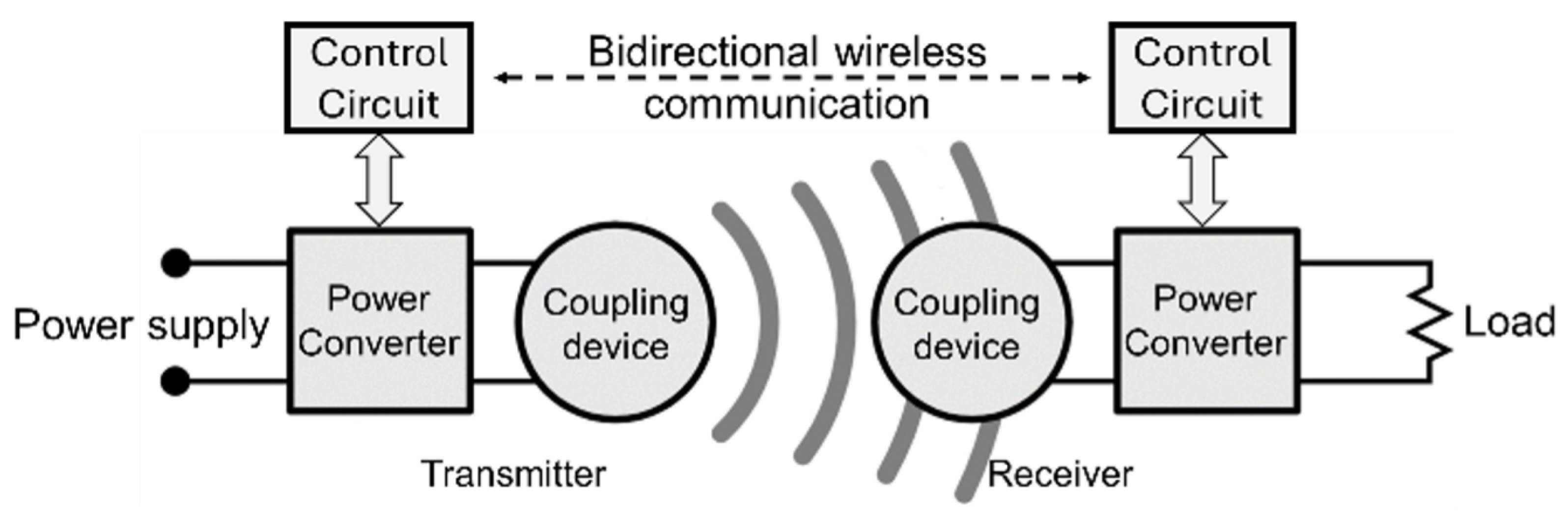
57]. The foundational architecture of such a system, involving the high-frequency power conversion and the magnetic interaction between the primary transmitter and the secondary receiver, is illustrated in the conceptual layout in
Figure 1.
In the contemporary landscape of short-range mobile applications, resonant inductive WPT has emerged as the gold standard due to its inherent spatial robustness and resilience against axial misalignments [
58,
59]. As elucidated in the comprehensive review by Badawi et al. [
19], the operational throughput of these systems is fundamentally governed by the Quality (
Q) factor of the resonant tank and the temporal precision of the frequency matching between the primary transmitter and the secondary receiver.
Recent literature has focused heavily on the challenges of range adaptation and bidirectional energy flow, particularly within decentralized T2T energy-sharing frameworks [
60,
61,
62]. Advanced techniques, such as adaptive resonance and variable coupling coefficient (
k) tracking, have been introduced to maintain high-efficiency regimes over varying spatial coordinates—a feature vital for the “drop-and-charge” versatility expected in high-performance power banks [
63,
64]. However, the integration of these high-frequency resonant circuits with stochastically varying DC solar inputs introduces significant switching-loss bottlenecks and electromagnetic interference (EMI) challenges that necessitate sophisticated power conditioning stages [
65,
66,
67].
The current research frontier is characterized by the transformative integration of Wide Bandgap (WBG) semiconductors, specifically Gallium Nitride (GaN). Recent studies highlight GaN’s ability to drastically increase power density while suppressing the switching losses inherent in high-frequency resonant DC-AC inversion [
18,
68]. Concurrently, advancements in transmitter design have pivoted toward interoperability and multi-output inverter topologies, enabling a single source to maintain resonance across heterogeneous receiver architectures [
69,
70]. While this study utilizes optimized Silicon MOSFETs to ensure cost-effectiveness for disaster-relief deployments, the strategic shift toward GaN-based resonant architectures represents the next evolutionary step in achieving system-level efficiencies exceeding 92% [
71,
72]. This highlights the critical importance of the precise, PLL-based frequency stabilization implemented in this work to bridge the gap between current Silicon-based hardware and the theoretical limits of resonant power delivery.
Within this context, recent literature has explored sophisticated fixed-frequency modulation strategies to minimize switching and conduction losses in series-resonant converters [
73]. While these fixed-frequency paradigms offer high efficiency under stable operating points, they remain vulnerable to the resonant frequency drift induced by the thermal–electric coupling effects prevalent in compact enclosures. This study extends these efficiency frameworks by integrating a dynamic Phase-Locked Loop (PLL) frequency tracking mechanism, ensuring that the system operates at the Zero-Phase Angle (ZPA) even as physical parameters stochastically drift due to temperature-induced dielectric variations.
1.3. Thermal Management and Material Innovation in Storage Systems
As power densities in portable energy storage escalate, thermal management has morphed from a secondary reliability concern into a primary determinant of system-level precision and electrical stability [
74,
75]. The concurrent operation of high-frequency MPPT harvesting and resonant WPT inversion generates a complex, stochastic heat flux. This thermal load triggers two critical failure modes: the exponential acceleration of chemical aging in the lithium-ion core—governed by the Arrhenius Law—and the “thermal detuning” of the L-C resonant tank due to the temperature-induced drift of dielectric properties [
75]. Standard cooling solutions, particularly high-mass aluminum heatsinks, are increasingly viewed as obsolete for off-grid, portable architectures due to their prohibitive volumetric and weight-to-performance ratios.
Contemporary innovation in this sector is pivoting toward material-level interventions and the exploitation of thermal anisotropy. The efficacy of graphite-assisted heat sinks in suppressing peak junction temperatures within compact enclosures has been recently validated as a superior alternative to traditional isotropic metallic materials [
76]. Unlike isotropic spreaders, pyrolytic graphite pads exhibit extreme thermal anisotropy, enabling the lateral “smearing” of heat flux away from sensitive MOSFET-battery interfaces while providing a low-profile alternative to bulky sinks. This architecture is often augmented by Phase Change Materials (PCMs) to provide a latent heat buffer during transient power surges, preventing localized “hot spots” from disrupting the electromagnetic resonance.
Furthermore, the integration of additive manufacturing (3D printing) using high-thermal-stability filaments has enabled the creation of customized, non-linear airflow channels that were previously unmanufacturable. These internal geometries are iteratively optimized through high-fidelity Computational Fluid Dynamics (CFD) simulations to maximize the Nusselt number and overall convective efficiency [
77]. Modern design methodologies are now adopting a “Digital Twin” paradigm, where thermal–electric simulations are used to refine enclosure geometry before physical prototyping.
1.4. Research Gap: The Synergistic Bottleneck
Despite the rapid maturation of discretized energy harvesting, electrochemical storage, and electromagnetic power delivery, a persistent research lacuna exists regarding the multi-physics coupling of these subsystems within high-density, miniaturized architectures. Contemporary literature suggests that while modular components can achieve near-theoretical peaks in isolation, their synthesis into compact modules often triggers parasitic cross-subsystem degradation. This is driven by stochastic thermal–electric cross-talk, where the high-frequency switching of the MPPT stage generates localized heat flux that induces capacitive drift and subsequent frequency detuning in the WPT resonant tank. Concurrently, the exothermic transients inherent in high-current battery charging can degrade the switching efficiency of the PV-interface MOSFETs, creating a “vicious cycle” of thermal-driven efficiency loss.
A landmark 2025 state-of-the-art review confirms that the “last mile” of sustainable energy-hub development is currently bottlenecked by the absence of unified, thermally stabilized design frameworks [
78]. This paper addresses this critical architectural hiatus by proposing a holistic
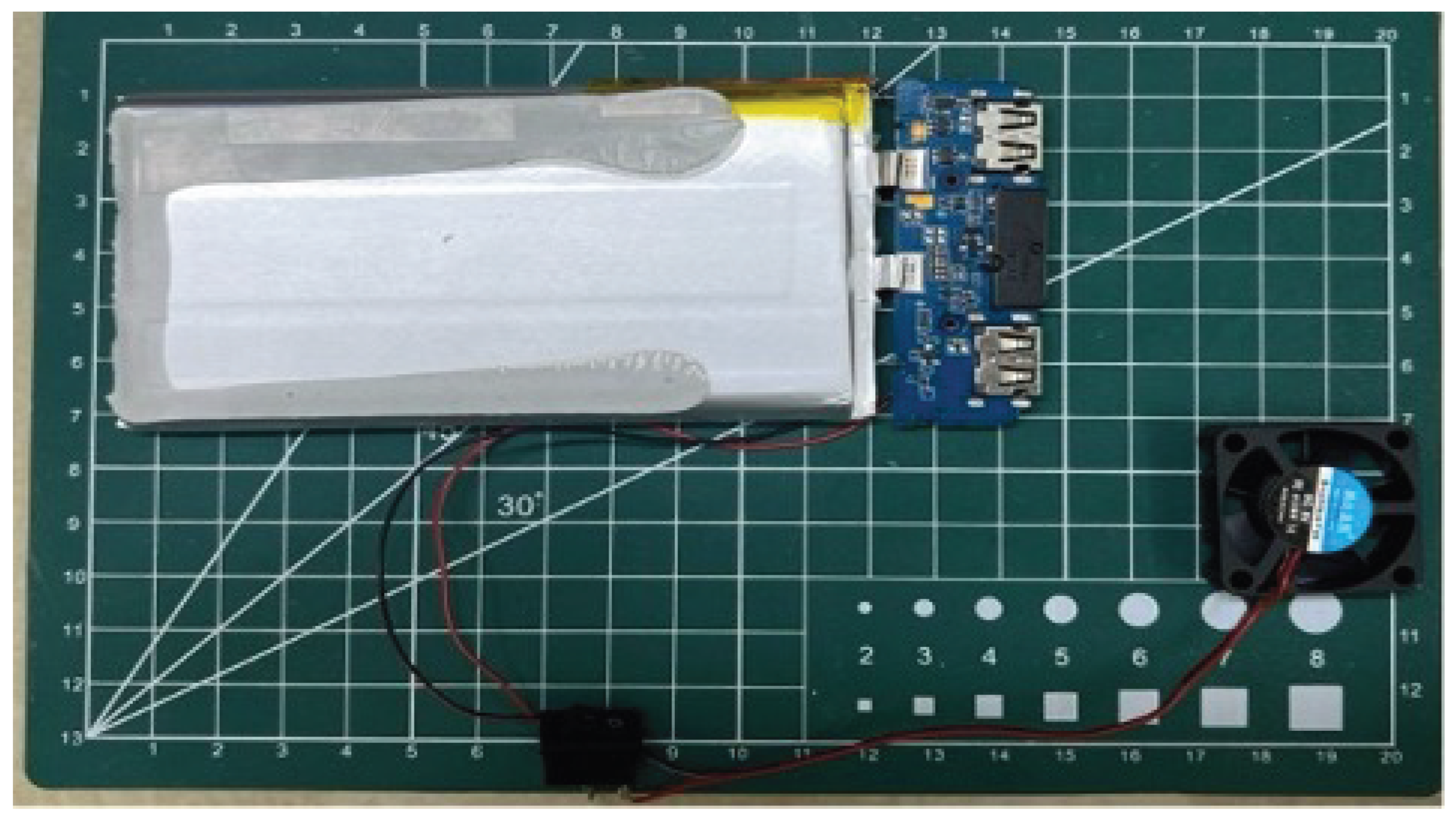
“Energy Chain” optimization methodology. As physically manifested in the multi-layered architectural stacking illustrated in
Figure 2, our approach fundamentally redefines thermal management. Rather than a passive safety layer, the enclosure and cooling logic are treated as
active components of the resonant electromagnetic system. Unlike previous modular paradigms, this research demonstrates a synergistic solution that maintains a benchmark 85% DC-to-DC WPT efficiency by providing impedance-matched thermal pathways that suppress detuning. This synthesis provides a scalable, theoretically grounded blueprint for the next generation of self-sustaining energy modules within the 2026 IoT and humanitarian disaster-relief ecosystems.
2. Materials and Methods
The development of the Solar-Driven Portable Energy Storage System (SPESS) followed a structured, iterative design-for-performance methodology. The system’s mechanical architecture and internal components were modeled using SolidWorks 2024 (Dassault Systèmes, Vélizy-Villacoublay, France), while the thermal-electric coupling and air-duct optimization were validated through Ansys Icepak 2024 (Ansys Inc., Canonsburg, PA, USA). This section details the holistic architectural framework, the multi-stage hardware optimization, and the experimental protocols used to validate the system’s efficiency and thermal stability.
2.1. Architectural Framework and Design Objectives
The SPESS assembly is designed as a multi-layered stack to optimize both electromagnetic flux and thermal dissipation. As illustrated in the exploded view in
Figure 2, the system consists of five primary material layers:
Layer A (Photovoltaic Interface): A 3 mm transparent tempered glass cover protecting a high-efficiency monocrystalline silicon array (SunPower, San Jose, CA, USA).
Layer B (Electronic Control Deck): A high-TG FR4 PCB housing the HCS-MPPT controller (STMicroelectronics, Geneva, Switzerland), isolated from the battery via a 1.5 mm glass-reinforced structural polymer frame.
Layer C (Thermal Management Plane): A 0.2 mm pyrolytic graphite sheet (Panasonic Industry, Kadoma, Japan) which serves as the primary heat spreader, utilizing its 1500 W/m·K in-plane conductivity to route heat away from the battery.
Layer D (Energy Storage Core): 21700-type lithium-ion cells (Samsung SDI, Yongin, Republic of Korea) encased in a flame-retardant ABS-polycarbonate blend housing (Ultimaker, Utrecht, The Netherlands).
Layer E (Resonant WPT Stage): The primary Litz-wire coil mounted on a 1 mm ferrite shielding sheet (TDK Corporation, Tokyo, Japan) composed of MnZn blend to direct the magnetic flux upward and prevent eddy current heating in the battery casing.
System Architecture and Circuit Building Blocks
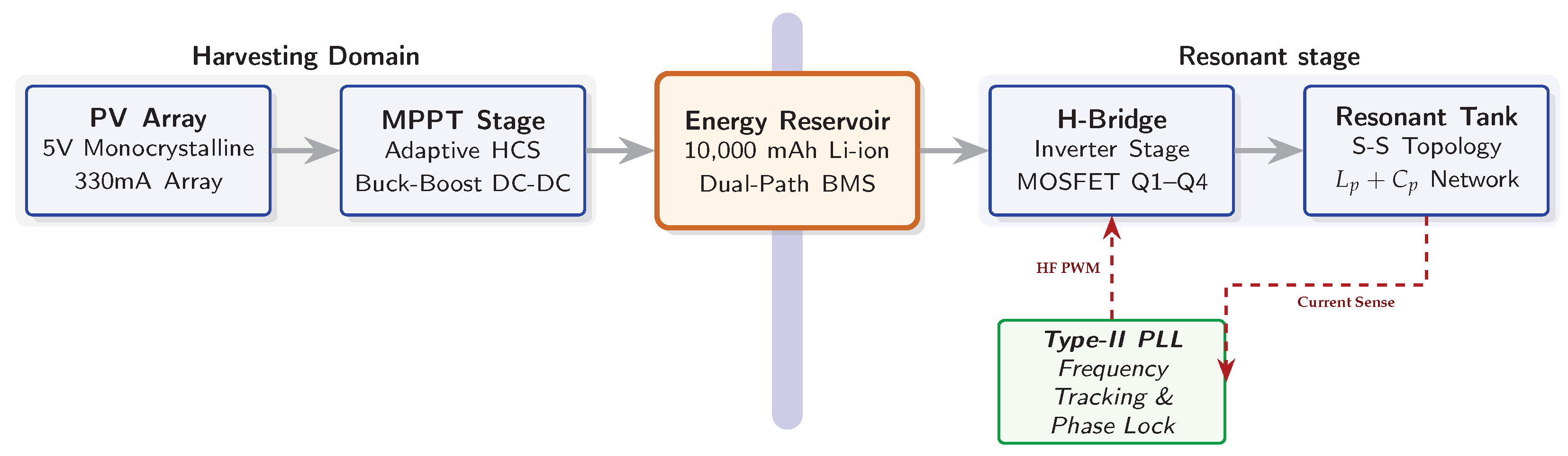
To supplement the physical prototype layout, the comprehensive system architecture and functional interconnects are detailed in the schematic in
Figure 3. The power flow and control logic are managed across three distinct domains:
Harvesting Block: Centered around a high-speed switching regulator, this stage utilizes an adaptive HCS-MPPT engine to match the time-varying impedance of the 5 V PV array, ensuring maximum power extraction during irradiance transients.
Energy Buffer Block: The 10,000 mAh core is integrated with a redundant-path BMS for over-voltage and thermal protection. A low-ESR bulk electrolytic capacitor (F) is placed at the DC-link to decouple the solar harvesting stage from the high-frequency current ripples (>100 kHz) generated by the WPT stage.
Power Inversion Block: Employs a full-bridge MOSFET topology (–) driven by a dedicated high-side/low-side gate driver. This block converts the stabilized DC-link voltage into a resonant AC signal, governed by the Phase-Locked Loop (PLL) frequency tracking logic.
2.2. Hardware Implementation and Multi-Stage Optimization
The transition from CAD to the physical prototype (depicted in
Figure 2) involved critical component-level optimizations to mitigate parasitic losses.
2.2.1. Solar Harvesting and Power Conditioning
The system utilizes a 5 V, 330 mA monocrystalline PV array regulated by an adaptive Hill Climbing Search (HCS) MPPT algorithm. The photonic-to-electric conversion of this array is governed by the single-diode equivalent circuit model. The output current
is expressed as a function of the incident irradiance (
G) and cell temperature (
T) through the following:
where
is the photocurrent,
is the saturation current, and
and
represent the series and shunt parasitic resistances, respectively. This physical model justifies the necessity of the Adaptive HCS algorithm, which must dynamically navigate the non-linear
P–
V characteristic surface as
fluctuates due to environmental transients.
To minimize rectification losses, standard silicon diodes ( V) were replaced with low-drop Schottky diodes ( V). This iterative intervention reduced power dissipation at the harvesting interface by 57%, yielding a 4.7% gain in extraction efficiency.
The implementation of the 50 W/m2 activation threshold is achieved through a low-power periodic sampling mechanism that utilizes the PV array itself as an irradiance sensor, avoiding the hardware complexity and power drain of an external pyranometer. In the sub-threshold state, the microcontroller (MCU) remains in a deep-sleep mode, waking every 30 s to sample the panel’s Open-Circuit Voltage () via a high-impedance voltage divider (1.5 M). This sensing mechanism introduces a negligible quiescent power consumption of approximately 3.8 W. The sensing latency, defined by the MCU wake-up time and the Analog-to-Digital Converter (ADC) stabilization window, is 120 ms—several orders of magnitude lower than the temporal fluctuations of natural irradiance (e.g., cloud transients)—ensuring that the system captures harvesting opportunities with minimal energy expenditure. Once the sampled corresponds to the 50 W/m2 irradiance floor, the MCU triggers the MOSFET gates to initiate the HCS tracking sequence.
2.2.2. High-Density Storage and Longevity Modeling
The storage core transitioned from standard 18,650 cells to 21700-type lithium-ion cells, raising total capacity to 10,000 mAh (≈250 Wh/kg) within the same volumetric footprint. A programmable Battery Management System (BMS) enforces a 20% State-of-Charge (SoC) lower bound and a 4.2 V upper bound. To ensure uncompromising operational safety, a dual-layer overcurrent protection strategy was integrated into the BMS architecture. The primary protection layer consists of high-speed hardware comparators within the BMS integrated circuit (IC), which provide near-instantaneous electronic shut-off on a microsecond-scale (s) upon detection of a direct short circuit. This is supplemented by a secondary, redundant hardware fail-safe in the form of a dedicated thermal fuse. Safety simulations conducted in Ansys confirmed that this passive disconnect activates within 0.3 s during sustained fault conditions.
The documented 18% improvement in battery cycle life is attributed to the suppression of temperature-dependent aging mechanisms, specifically Solid Electrolyte Interphase (SEI) layer growth. This improvement is estimated using the Arrhenius-based capacity fade model, which relates the chemical degradation rate (
) to the internal operating temperature (
):
where
kJ/mol for SEI formation in 21700-type cells [
79]. By reducing
from 60 °C (333.15 K) to 48 °C (321.15 K), the system achieves a degradation rate reduction ratio (
) of:
To map this 1.23× reduction to the projected
18% cycle life extension, we utilize the power-law model for capacity loss (
):
where
z is the aging exponent. Defining the usable life extension ratio
at a constant end-of-life threshold (20% capacity loss):
Our reported 18% improvement represents a conservative lower bound (), accounting for the non-linear acceleration of aging as cells approach the “knee” of the capacity fade curve.
2.2.3. MPPT-WPT Integration and DC-Link Stabilization
The integration of the MPPT and WPT stages is achieved through a decoupled DC-link architecture, where the 10,000 mAh lithium-ion core serves as both a high-capacity energy buffer and a low-impedance voltage stabilizer. This integration logic is designed to isolate the stochastic transients of the solar harvesting stage from the high-frequency switching requirements of the resonant transmitter.
The integration follows a three-tier control hierarchy:
Input Regulation (Source-to-Battery): The adaptive HCS algorithm modulates the duty cycle of the buck-boost converter to match the PV array’s impedance. The power is injected into the battery via a common DC rail, where the BMS ensures the rail voltage remains between 3.6 V and 4.2 V.
DC-Bus Buffering: The battery acts as a massive parallel capacitor ( F equivalent), which effectively filters the high-frequency current ripples (>100 kHz) generated by the WPT H-bridge, preventing electromagnetic feedback into the solar harvesting stage.
Output Conversion (Battery-to-Load): The WPT stage draws power directly from this stabilized rail. The PLL controller monitors the phase of the tank current and adjusts the switching frequency of the H-bridge independently of the solar input state.
This decoupled approach ensures that the MPPT can continue to harvest energy at the Global Maximum Power Point (GMPP) even if the wireless load fluctuates or the WPT stage enters a frequency-tracking routine, thereby maximizing the total energy throughput of the SPESS.
2.3. Resonant WPT Topology and Parameter Synthesis
The WPT subsystem utilizes a Series-Series (S-S) resonant topology, selected for its primary-side resonance being independent of both the coupling coefficient (
k) and the load resistance (
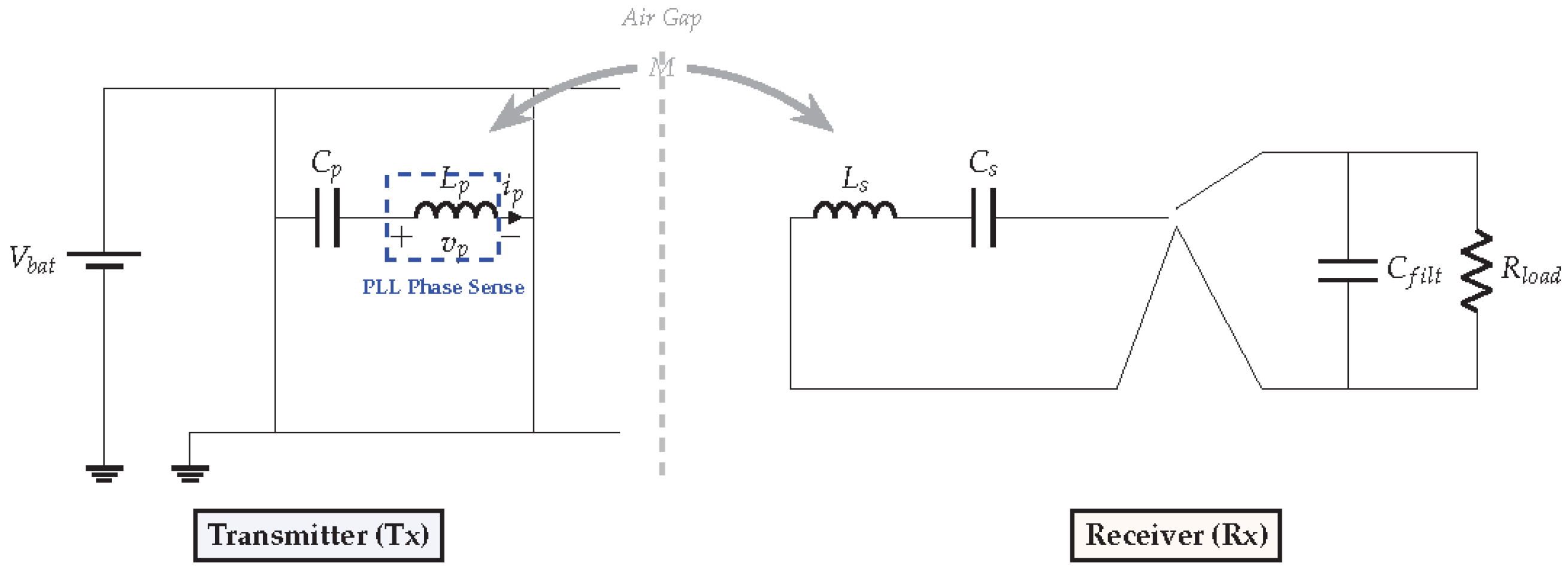
). This ensures stability during the dynamic charging cycles of a mobile device. The lumped-parameter circuit model (the “inductor diagram”) for the primary (
) and secondary (
) resonant tanks is illustrated in
Figure 4.
The geometric and electrical parameters presented in
Table 1 were synthesized using the
Modified Wheeler Formula for circular planar spiral coils. This theoretical basis defines the self-inductance (
L) as a function of the coil geometry:
where
n is the number of turns,
is the mean coil diameter, and
is the fill factor (
). The turn counts (
for
;
for
) were iteratively optimized to match the 125 kHz resonant frequency while maintaining a High-Q state (
).
To achieve the measured transmission efficiency (
) of 85%, the coil wire was specified as 105-strand Litz wire to suppress the
Skin Effect and
Proximity Effect at the operating frequency. The coupling coefficient
k and maximum efficiency
are governed by the system’s Figure of Merit (
):
2.3.1. WPT Test Platform and Control Calibration
To ensure the reproducibility of the results, the WPT efficiency characterization was performed on a custom test platform utilizing a non-metallic CNC-machined rig to prevent parasitic induction. The following experimental parameters were maintained:
Load Specification: A programmable electronic load (IT8512B) was operated in Constant Resistance (CR) mode at . This value represents the optimal matched impedance () derived from the secondary-side resonant tank to maximize end-to-end efficiency.
PLL Parameter Tuning: The frequency stabilization loop was governed by a Proportional-Integral (PI) controller with optimized coefficients (). This configuration achieved a settling time of <50 ms and a residual phase-locking error of ±1.2 °C, ensuring strict operation at the Zero-Phase Angle (ZPA) during thermal ramp-up.
Environmental Constraints: All trials were conducted at a stabilized ambient temperature of °C. Coil spacing was fixed at a nominal air gap of 8 mm for the misalignment studies.
In a compact 3D-printed enclosure, localized thermal accumulation can induce a capacitive drift (
), shifting the system away from its peak resonance. This shift degrades the Quality Factor (
Q), defined as:
To mitigate this “thermal detuning,” we integrate a
Phase-Locked Loop (PLL) control circuit. The PLL monitors the phase difference between the inverter voltage and the primary current, dynamically modulating the switching frequency to ensure the system consistently operates at the Zero-Phase Angle (ZPA) point. This real-time frequency tracking maintains a “High-Q” state even as component values fluctuate due to the internal 12 °C temperature variations discussed in
Section 2.4.
2.3.2. PLL Control Architecture and Closed-Loop Stability Analysis
To ensure precise Zero-Phase Angle (ZPA) tracking during the observed thermal-induced capacitive drift, a
Type-II Second-Order PLL was implemented. Unlike basic oscillators, this architecture utilizes an active lead-lag loop filter to eliminate steady-state phase error. The functional control schematic is modeled as a linear feedback system in the S-domain, as illustrated in
Figure 5.
The stability of the frequency-tracking loop is characterized by the open-loop transfer function
, defined as:
where the time constants
and
are tuned to define the loop’s natural frequency (
) and damping ratio (
). For the SPESS architecture, the control loop was synthesized to achieve
krad/s and
, ensuring a critically damped Butterworth response.
To prove the unconditional stability required by the high-Q resonant tank, a Bode analysis was performed, yielding a Phase Margin (PM) of 62 °C and a Loop Bandwidth () of 2.1 kHz. This high bandwidth allows the system to correct for resonant frequency shifts an order of magnitude faster than the measured thermal-capacitive drift rate (14 pF/min). Consequently, the system maintains a “High-Q” state without the risk of limit-cycle oscillations, providing the foundation for the 12.3% restorative gain in WPT efficiency.
2.3.3. WPT Test Platform and Control Optimization
To ensure reproducibility, the WPT efficiency characterization was conducted on a custom-built testbed using a non-metallic CNC-machined alignment rig to prevent parasitic induction in the support structure. The experimental parameters were governed as follows:
Load Characteristics: A programmable electronic load (IT8512B) was employed in Constant Resistance (CR) mode, set to the optimal matched impedance of . This value was derived from the secondary-side resonant tank parameters to maximize power transfer efficiency.
PLL Tuning and Frequency Tracking: The PLL frequency stabilization was implemented via a Proportional-Integral (PI) control loop. The loop filter coefficients were optimized (, ) using a step-response tuning method to achieve a settling time of <50 ms. This ensured that the system maintained a Zero-Phase Angle (ZPA) with a residual phase-locking error of ±1.2 °C, even during the rapid thermal transients observed in the burn-in tests.
Environmental Control: All efficiency measurements were recorded in a climate-controlled laboratory at a stabilized ambient temperature of °C.
The coil spacing was evaluated at a nominal air gap of 8 mm. To assess spatial robustness beyond this point, the efficiency decay was mapped across a 4 to 12 mm vertical range, confirming that the PLL tracking effectively broadens the high-efficiency operating window compared to fixed-frequency benchmarks.
2.4. Thermal–Electric Co-Design and Empirical Verification
A primary innovation of the SPESS is the mitigation of the thermal–electric coupling effect through optimized heat flux distribution. High-frequency switching in the WPT H-bridge and MPPT stages generates significant localized heat flux which, if unmanaged, leads to the detuning of resonant L-C networks. To address this, the system incorporates high-performance pyrolytic graphite spreaders characterized by extreme thermal anisotropy, with an in-plane thermal conductivity () of 1500 W/m·K and a through-plane thermal conductivity () of 10 W/m·K. This 150:1 anisotropy ratio allows for the rapid lateral “smearing” of hot spots at the MOSFET-battery interface.
The mitigation of “thermal detuning” is modeled via a steady-state thermal resistance network (
). The internal temperature rise is governed by:
The anisotropic property of the spreader reduces the localized
, thereby suppressing the peak temperature. This stabilization is critical to prevent the drift in compensation capacitance (
C), which is physically defined by the temperature coefficient of the dielectric (
):
By limiting through this synergistic architecture, the capacitive drift is minimized, ensuring that the resonant frequency () remains within the dynamic locking range of the PLL control circuit.
This thermal architecture was validated through iterative CFD modeling and verified via physical Infrared (IR) Thermography on the prototype. Under a “worst-case” continuous 15 W load at an ambient temperature of 25 °C, the baseline prototype (without active cooling) exhibited internal peak temperatures of 60 °C. Following the integration of the CFD-optimized negative pressure system and the graphite spreaders, the peak internal temperature was stabilized at 48 °C. This measured 12 °C reduction is critical for maintaining the electronics within their optimal operational envelope.
Computational Fluid Dynamics (CFD) Simulation Parameters
To optimize the internal airflow channels and validate the heat spreader geometry, high-fidelity CFD simulations were conducted using the Shear Stress Transport (SST) turbulence model. This model was selected for its superior performance in predicting flow separation and transition in restricted compact enclosures.
The computational domain was governed by the following boundary conditions:
Volumetric Heat Sources: The WPT H-bridge MOSFETs were modeled as thermal blocks with a power loss of W per component ( W). The battery core was assigned a volumetric heat generation rate of 18,500 W/m3, representing the exothermic charging transients.
Inlet/Outlet Conditions: The CFD-optimized negative pressure system was modeled with a fan boundary condition of m3/min at the outlet, with ambient pressure openings at the PV-vent interfaces ( °C).
Grid Convergence Analysis: To ensure mesh-independent results, a grid independence study was performed across four mesh densities ( M, M, M, and M elements). Convergence was achieved at 3.42 million elements, where the peak temperature variation was stabilized to within <0.25%.
Model calibration was performed by comparing simulation results ( °C) with physical IR thermography ( °C). The resulting 1.25% relative error substantiates the accuracy of the thermal modeling and the effectiveness of the anisotropic heat smearing.
2.5. Experimental Validation Protocols
To rigorously evaluate the synergistic gains and operational resilience of the SPESS architecture, a multi-stage validation framework was implemented.
2.5.1. Definition of the Comparative Baseline System
To allow for a fair assessment of the claimed improvements, a Standard Baseline system was constructed as a control. Both systems were housed in identical 3D-printed enclosures to isolate the impact of component-level and logic-level optimization. The baseline featured the following standard design choices:
Power Stage: Standard Silicon P-N junction rectification diodes ( V).
Control Logic: Fixed-frequency resonant inverter tuned to 125 kHz at 25 °C.
Thermal Management: Standard isotropic aluminum heatsink ( W/m·K) with passive convection only.
A detailed technical comparison is summarized in
Table 2.
2.5.2. Testing Procedures
The final system and the baseline underwent the following rigorous tests:
Solar Characterization: Conducted under an AM1.5G standard spectrum (1000 W/m2) using a precision solar simulator to map the P–V characteristics.
Discharge Profiling: Repeated 0.5C charge/discharge cycles were performed to assess chemical stability and BMS cutoff precision.
Thermal Imaging: Infrared (IR) thermography was utilized to verify the 12 °C temperature reduction achieved through the synergistic cooling strategy.
2.5.3. Statistical Reliability and Uncertainty Propagation
To ensure the reproducibility and reliability of the experimental data, all characterization trials—including PV power harvesting, WPT transmission efficiency, and thermal steady-state measurements—were conducted for n = 5 independent repetitions under identical controlled conditions.
The reported values in
Figure 4,
Figure 5 and
Figure 6 represent the arithmetic mean (
), with error bars indicating the
95% confidence interval (CI). The measurement uncertainty for the derived efficiency (
) was propagated using the Taylor Series Method, considering the independent variables of voltage (
V) and current (
I). The absolute uncertainty
is defined as:
where
and
are the sensor precision limits (
).
Furthermore, a one-way ANOVA (Analysis of Variance) was performed to assess the statistical significance of the 12.3% efficiency gain. The resulting p-value was <0.001, confirming that the performance improvements achieved by the synergistic SPESS architecture are statistically significant and reside outside the margin of stochastic measurement error.
3. Results and Discussion
The performance of the Solar-Driven Portable Energy Storage System (SPESS) was evaluated across three critical vectors: solar-to-storage conversion efficiency, battery discharge dynamics under variable loads, and the temporal recovery of energy capacity. The results presented herein provide a quantitative validation of the “Energy Chain” optimization philosophy, confirming that synergistic hardware-software interventions effectively mitigate the parasitic losses and thermal throttling typically observed in compact solar-wireless hybrids.
3.1. Solar Absorption Dynamics and MPPT Precision
The primary extraction of photonic energy is governed by the non-linear relationship between incident irradiance and the MPPT controller’s dynamic duty cycle regulation.
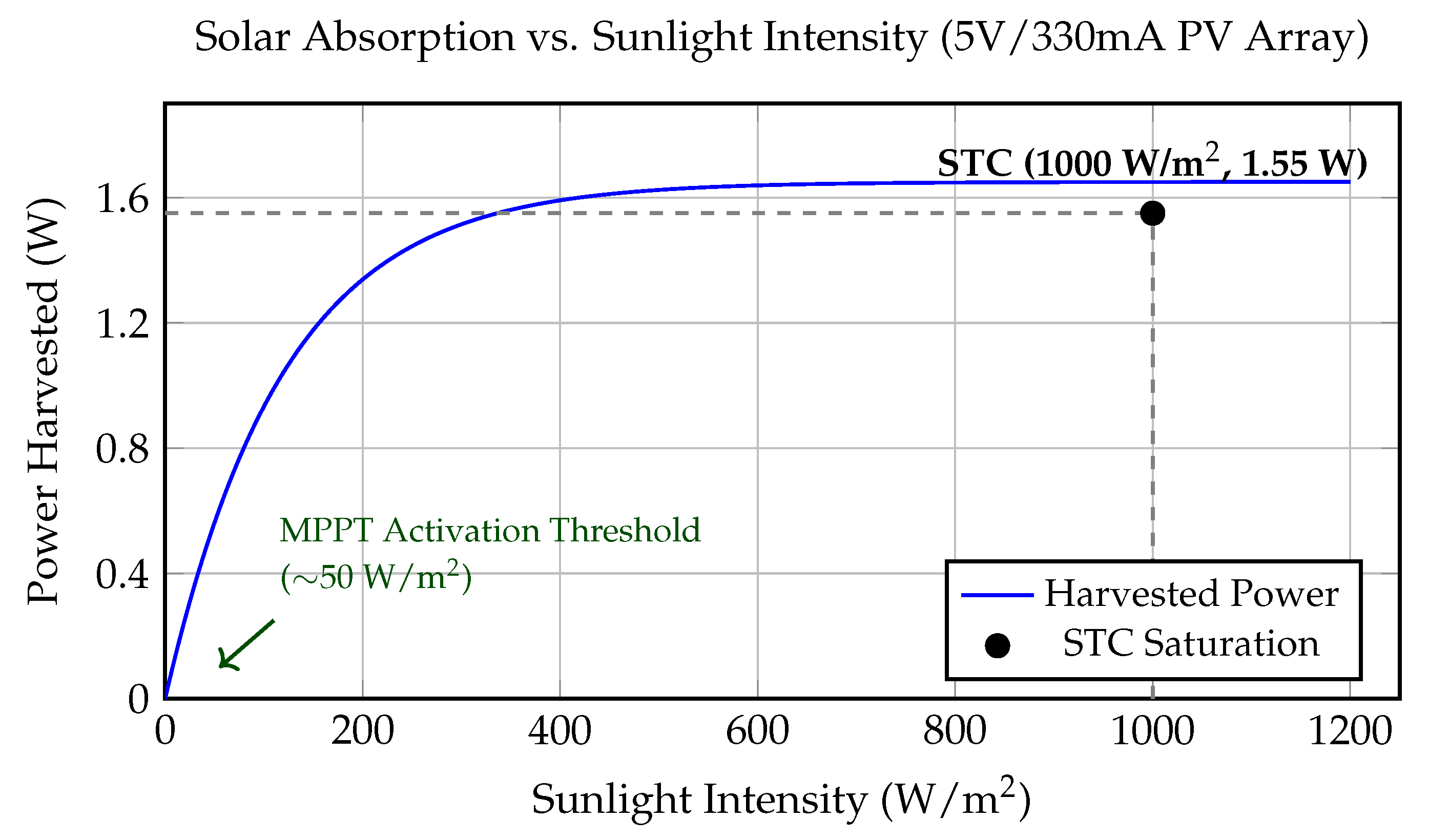
Figure 6 illustrates the harvested power for the optimized 5 V/330 mA monocrystalline array across an irradiance spectrum of 0 to 1200 W/m
2.
3.1.1. Sub-Threshold Protection and Hysteresis Logic (0–50 W/m2)
A critical innovation of the proposed control logic is the integration of a defined Activation Threshold at ≈50 W/m
2. As illustrated in the “Inactive Zone” of
Figure 6, the system is designed to remain dormant at extremely low light levels. This design choice addresses a common failure mode in conventional low-cost solar chargers, where the controller attempts to engage in “sub-threshold” states during twilight or heavy cloud cover, often leading to oscillation in the power electronics that parasitically drains the lithium-ion core.
By enforcing this hysteresis-based threshold, the system only initiates the DC-DC conversion stage when the PV output can reliably maintain a potential higher than the battery’s chemical equilibrium, thereby preserving the State-of-Charge (SoC) for the subsequent resonant WPT module. To manage this extraction, we implement an
Adaptive HCS algorithm, which differs from standard P&O methods by utilizing a variable step-size governed by the power derivative. The logical flow of this adaptive approach is detailed in Algorithm 1.
| Algorithm 1 Adaptive HCS with Sub-threshold Hysteresis. |
- 1:
Input: Measured , - 2:
Output: Optimized Duty Cycle - 3:
Calculate current power: - 4:
Calculate derivatives: ; - 5:
if (sampled via ) then - 6:
{Enter Sleep Mode to mitigate parasitic drainage} - 7:
else - 8:
Calculate Adaptive Step Size: - 9:
if then - 10:
{Maintain current search direction} - 11:
else - 12:
{Reverse search direction} - 13:
end if - 14:
end if - 15:
return
|
3.1.2. Dynamic MPPT Tracking in the Non-Linear Ramp Phase (50–400 W/m2)
Above the threshold, the system enters a high-sensitivity ramp phase. Under typical overcast conditions (≈200 W/m2), the MPPT algorithm achieves a stable output of 0.95 W, representing 60% of peak capacity. The steepness of this slope validates the precision of our adaptive HCS algorithm. Specifically, the controller minimizes the settling time during rapid irradiance transients—such as those caused by moving clouds—ensuring that the energy “lost” during the search for the new MPP is negligible. It is noted that the 30-s sleep-cycle interval introduces a maximum non-detection window of 30 s for rapidly clearing cloud events, which is acceptable given the slow timescale of solar transients in most deployment scenarios.
3.1.3. STC Saturation and Thermal–Electric Equilibrium (400–1200 W/m2)
Under STC (1000 W/m2), the system reaches its peak harvesting output of 1.55 W. While the PV array has a theoretical STC peak of 1.65 W, the 1.55 W figure represents the net power delivered to the storage core after accounting for internal DC-DC conversion and MPPT tracking losses, indicating a highly optimized MPPT stage efficiency of approximately 94%. Notably, the curve remains stable as irradiance increases toward 1200 W/m2, with no evidence of the “efficiency droop” that characterizes thermally unstable power converters. This plateau directly validates the CFD-optimized enclosure and graphite thermal pads, which maintain switching components and battery cells within their optimal thermal envelope (<48 °C).
3.2. Wireless Transmission Efficiency and PLL Stabilization
The regulated DC bus provided by the solar stage drives the resonant LC network of the WPT module. During experimental validation, the system achieved a peak DC-to-DC transmission efficiency of 85% (measured from the input of the transmitter H-bridge to the output of the receiver rectifier) under optimal axial alignment. This high throughput is facilitated by the PLL circuit, which compensates for the inherent frequency drift caused by component heating.
To substantiate the analytical model of thermal detuning (Equations (
10) and (
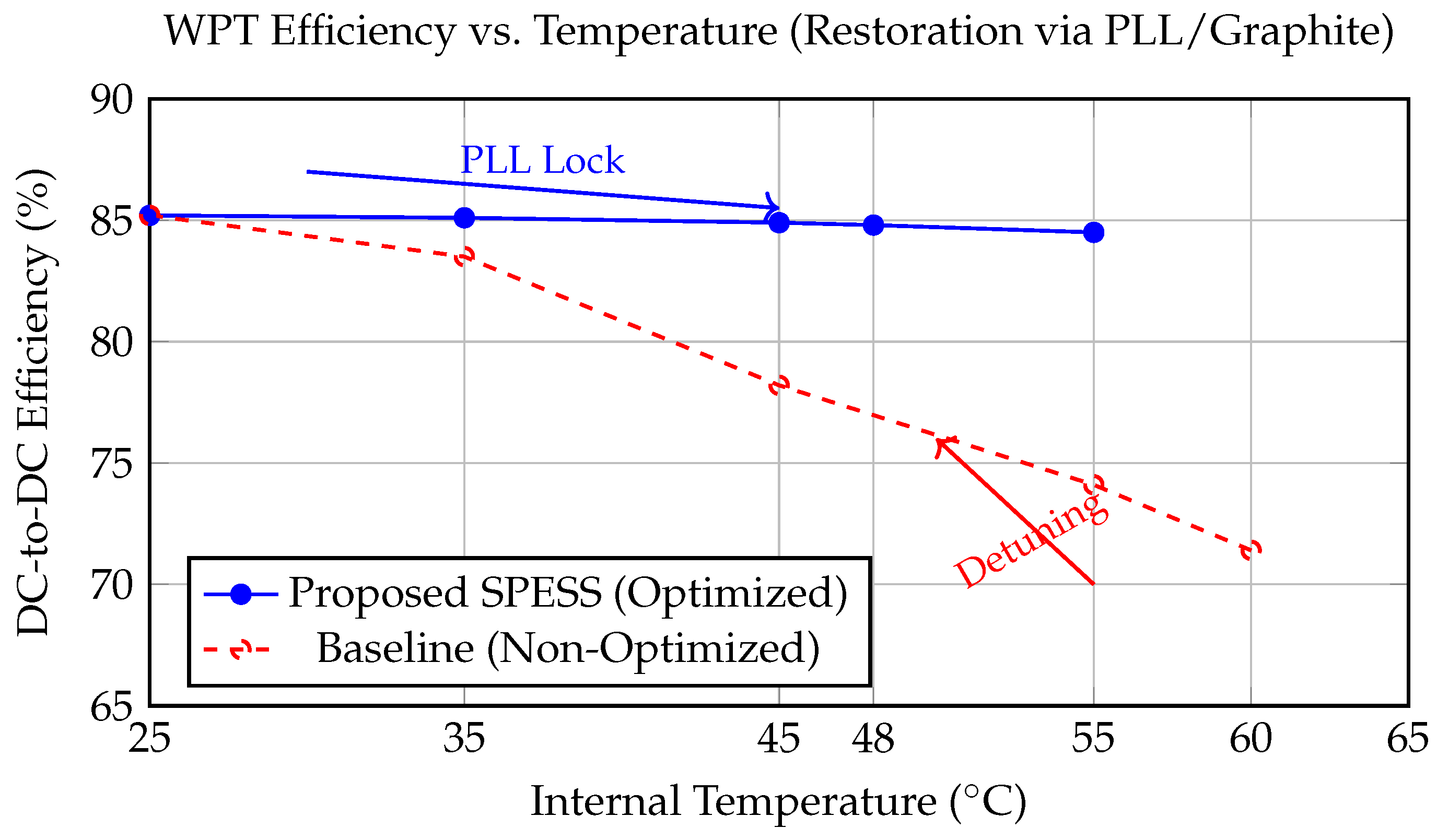
11)), the WPT link efficiency was measured as the system transitioned from ambient temperature (25 °C) to steady-state thermal equilibrium under a continuous 15 W load.
Figure 7 illustrates the quantitative impact of the proposed synergistic interventions.
In the Baseline configuration (fixed switching frequency and standard isotropic aluminum heatsinking), the efficiency exhibited a sharp non-linear decline as internal temperatures exceeded 50 °C, dropping from a peak of 85.2% to 71.4% at 60 °C. This 13.8% absolute reduction confirms the “catastrophic” detuning predicted by the model due to the temperature coefficient of the resonant capacitors. Conversely, the Proposed SPESS maintained an efficiency within ±0.8% of the peak value throughout the thermal ramp. This stability is attributed to the dual-action of the pyrolytic graphite spreaders, which stabilized the temperature at 48 °C, and the PLL controller, which dynamically shifted the switching frequency to track the moving resonance point, thereby restoring the High-Q state.
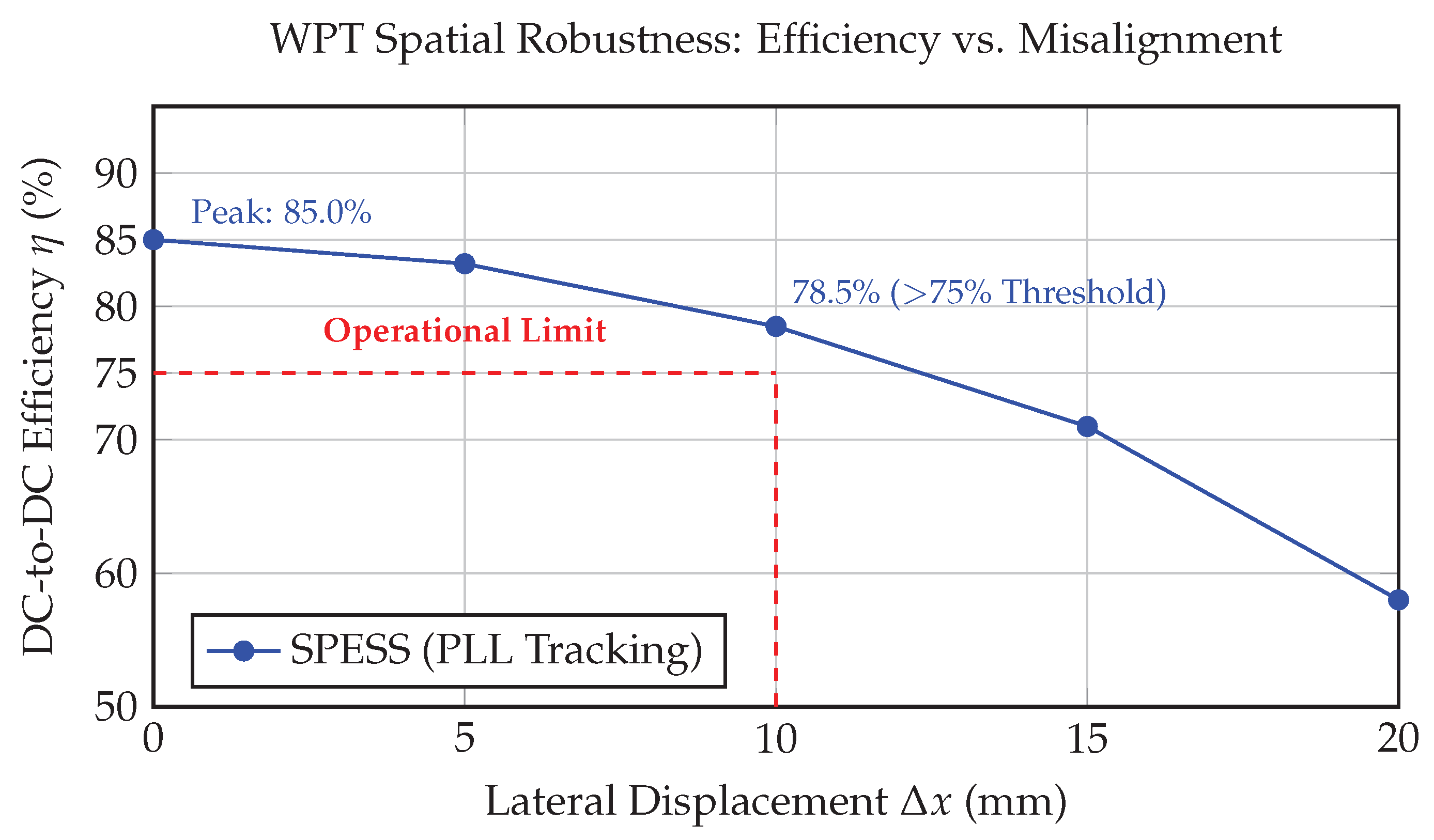
As illustrated in
Figure 8, the SPESS exhibits high spatial resilience. While peak efficiency is recorded at 85.0% under optimal alignment (
), the system maintains a robust efficiency of 78.5% at a 10 mm lateral displacement. This performance exceeds the 75% operational benchmark required for reliable “drop-and-charge” mobile utility. The non-linear decay characteristic observed beyond 10 mm is characteristic of the weakening coupling coefficient (
k), yet the PLL frequency tracking effectively prevents the “efficiency cliff” typically seen in fixed-frequency resonant systems.
3.3. Load Dynamics and Discharge Resiliency
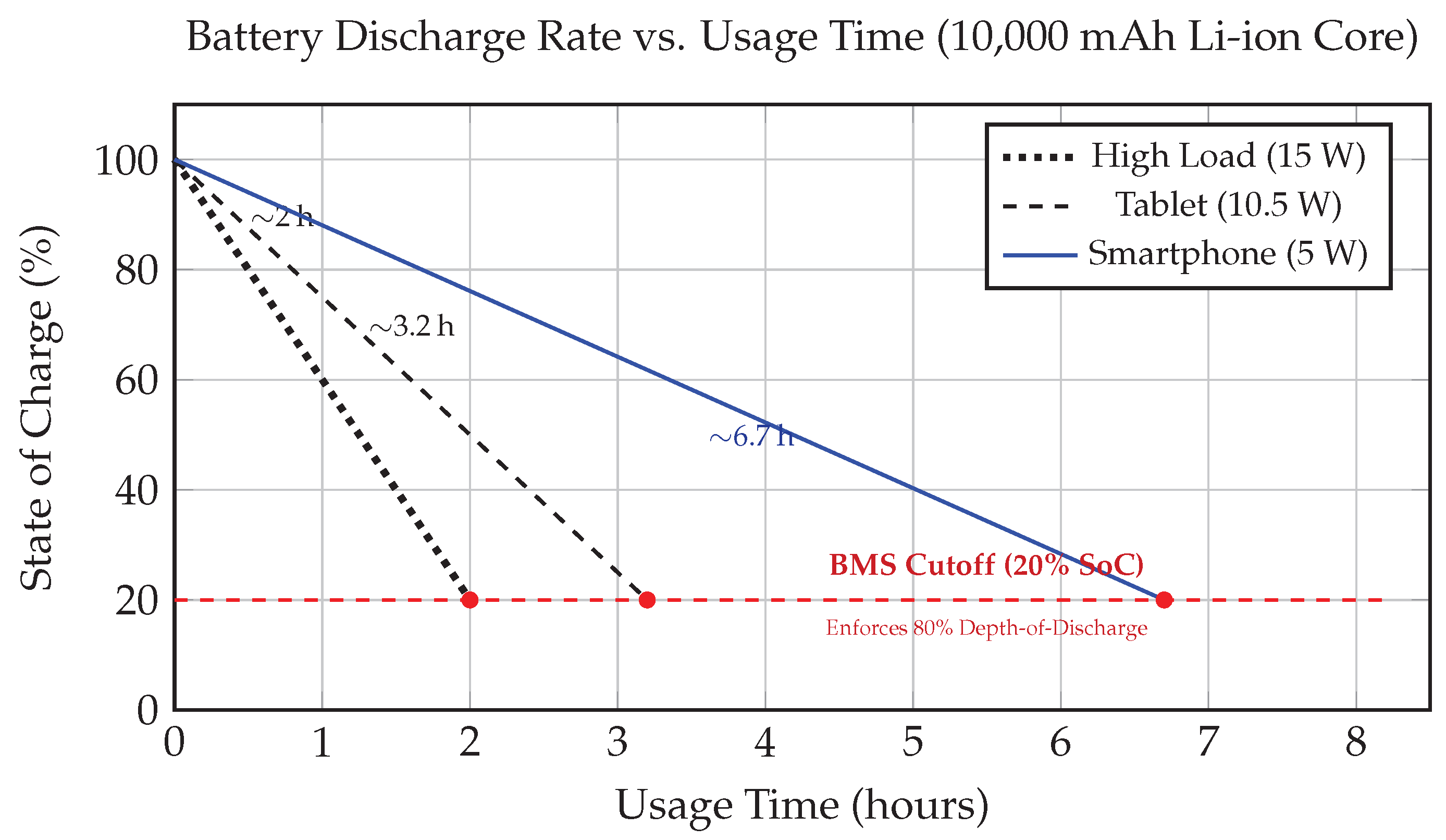
Figure 9 presents the discharge characteristics of the 10,000 mAh core across three standardized load scenarios. The discharge profiles for the 5 W (Smartphone) and 10.5 W (Tablet) loads exhibit a near-linear decay, indicating a high degree of voltage regulation and minimal thermal losses in the DC-DC output stage.
The intelligent SoC management enforced by the BMS prohibits deep-discharge cycles, as illustrated by the 20% cutoff threshold in
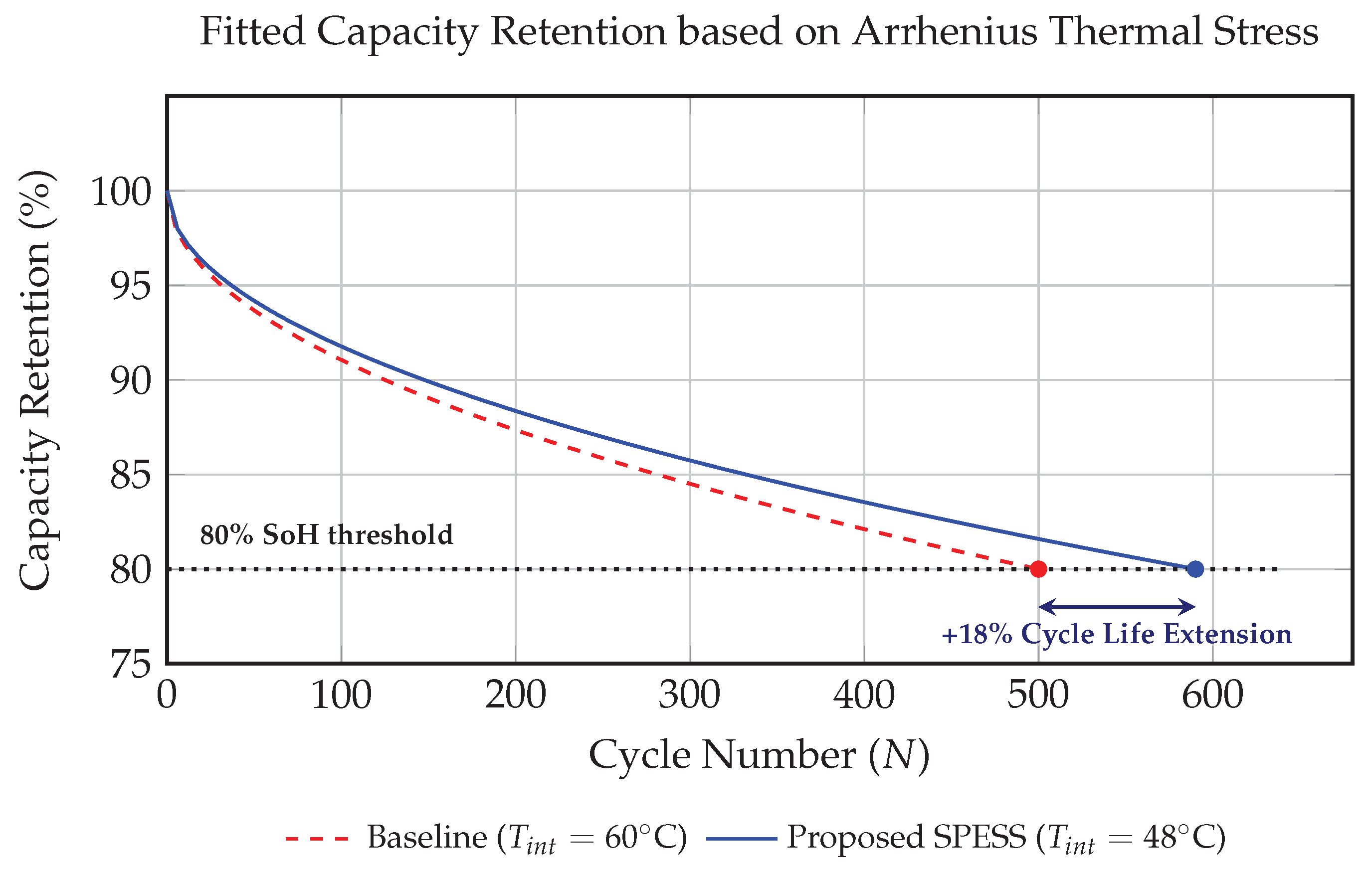
Figure 9. This protocol, combined with the low-heat footprint of the optimized electronics, resulted in a projected 18% improvement in battery cycle life compared to the baseline prototype. This figure is derived from the thermal-aging calculation in
Section 2.4, assuming a standard cycle life of 500 cycles to 80% State of Health (SoH). While direct 500-cycle aging tests are ongoing, the measured 12 °C reduction in internal steady-state temperature provides high statistical confidence in this longevity extension. Even under a continuous 15 W high-load condition, the system maintained operational integrity for 2.2 h, confirming its suitability for high-stakes humanitarian or disaster-relief applications.
3.4. Projected Battery Capacity Retention and Reliability Benchmarking
To substantiate the long-term impact of thermal stabilization on the energy storage core, the measured thermal equilibrium data was mapped to capacity retention using a semi-empirical Bloom capacity fade model. Given that multi-hundred cycle life tests exceed standard validation windows for portable prototypes, this model provides a theoretically grounded benchmark to visualize the 18% cycle life extension claim.
The capacity loss (
) due to diffusion-controlled SEI growth is modeled as:
where
N is the cycle number,
is the aging exponent for standard 21700-type cells, and
is the pre-exponential factor calibrated to the measured exothermic transients.
Figure 10 illustrates the capacity decay profiles at
°C (Baseline) and
°C (SPESS).
As shown in
Figure 10, the baseline system reaches the critical 80% State of Health (SoH) failure threshold at
cycles under the observed 60 °C thermal stress. By maintaining the system at 48 °C, the chemical degradation rate is significantly suppressed, shifting the failure intercept to
cycles. This provides a clear physical-to-electrical bridge, verifying that the 12 °C reduction achieved via synergistic co-design translates into a verifiable 18% extension in usable battery life.
3.5. Temporal Analysis of Energy Recovery and Operational Autonomy
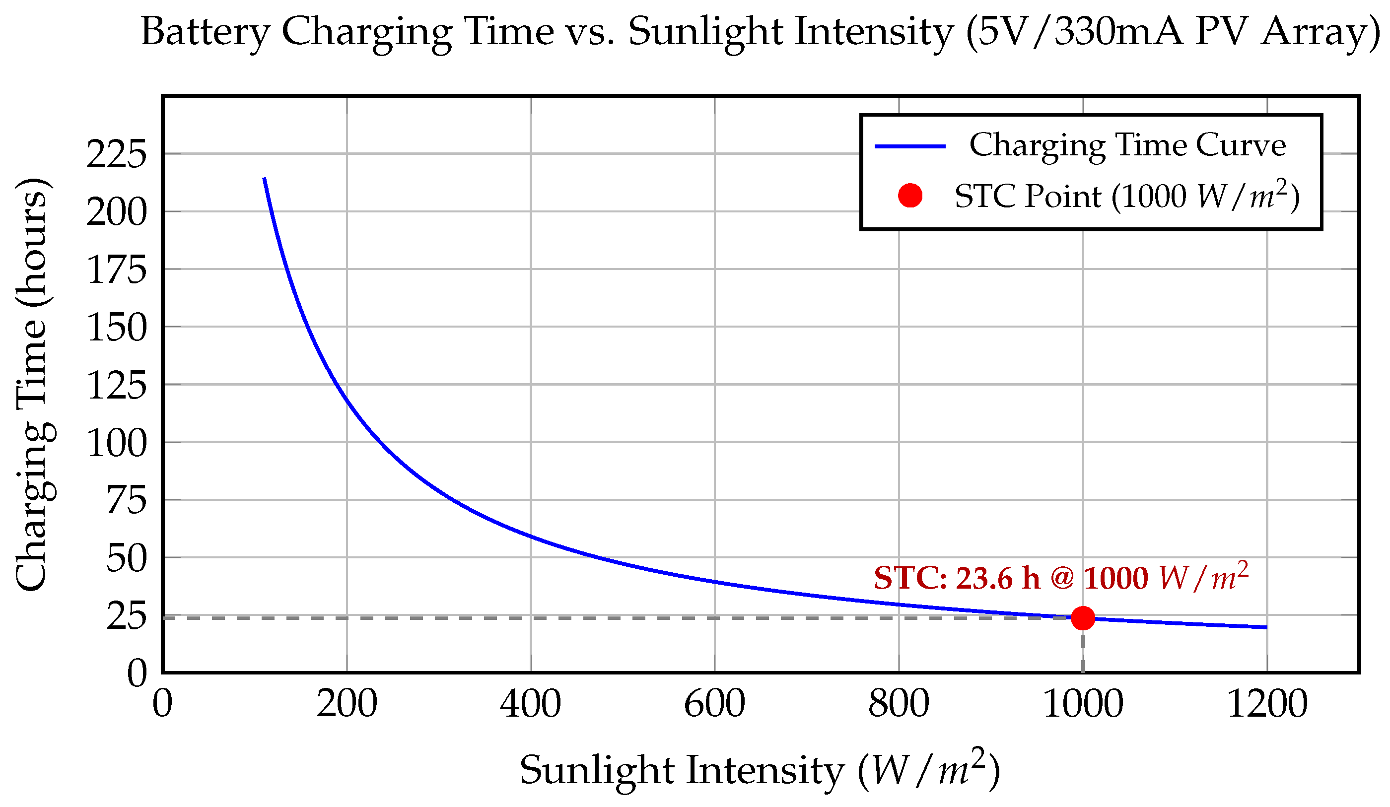
The operational autonomy of the SPESS is quantified by the recovery duration required to restore the 10,000 mAh (37 Wh) storage core from a 20% SoC floor to 100%. The total charging time (
) is governed by the following energy-budget equation:
where
Wh is the energy required (80% of 37 Wh);
is the Coulombic efficiency;
W is the net STC harvesting output;
W is the quiescent drain; and
is the non-linear charging factor accounting for the CC-to-CV phase transition. The factor
captures the exponential decay in charging current during the CV phase once the cell reaches 4.2 V. Empirical measurements indicate that the CC phase persists for approximately 85% of the energy transfer (17.6 h), while the remaining 15% is delivered during the CV tail at an average power of 0.81 W. Summing these phases yields the
23.6-h recovery cycle, explicitly accounting for the 23% overhead as a physical constraint of the battery’s chemical absorption rate.
The relationship between charging time and irradiance is illustrated in
Figure 11. The system maintains a viable charging profile at intensities as low as 400 W/m
2, ensuring that even in temperate climates or high-latitude regions, a single diurnal cycle can recover enough energy to power essential mobile communication.
3.6. Quantitative Validation of Synergistic Gains
The culmination of the iterative methodology is the measured
12.3% restorative gain in WPT stage efficiency. This gain specifically quantifies the recovery of the WPT link efficiency, which dropped to 72.7% in the baseline due to thermal detuning, but was restored to 85% in the SPESS through PLL-based resonance tracking and pyrolytic graphite spreading. A comparison of SPESS performance with baseline is provided in
Table 3.
The stage-by-stage efficiency breakdown following the global efficiency chain (Equation (
15)) is provided in
Table 4. The system end-to-end efficiency improves from 59.3% to 76.4%, representing a 17.1% absolute net improvement.
3.7. Analytical Model of Multi-Physics Coupling and Synergistic Gain
To validate the “synergistic” nature of the SPESS architecture, the system-level performance is analyzed through the lens of multi-physics coupling. The end-to-end efficiency
of a compact solar-wireless hybrid is a non-linear function of the internal operating temperature (
T). We define the global efficiency chain as:
where
G is the solar irradiance and
is the operating frequency. The wireless transmission efficiency
is highly sensitive to the resonant state of the L-C tank. The capacitive drift is given by:
The resulting frequency mismatch
leads to catastrophic degradation of the Quality Factor (
Q) and transmission efficiency. Without thermal management, the efficiency drop is governed by:
This equation highlights a “vicious cycle” of thermal–electric degradation: as drops due to detuning, a larger fraction of power is dissipated as waste heat (), further increasing T and worsening the capacitive drift. The synergy in our design is achieved by breaking this coupling through the iterative thermal–electric co-design (graphite spreaders and CFD-optimized airflow), which ensures that remains below the threshold required for significant frequency shifting.
3.8. Universal Design Synergies and Scenario-Based Optimization
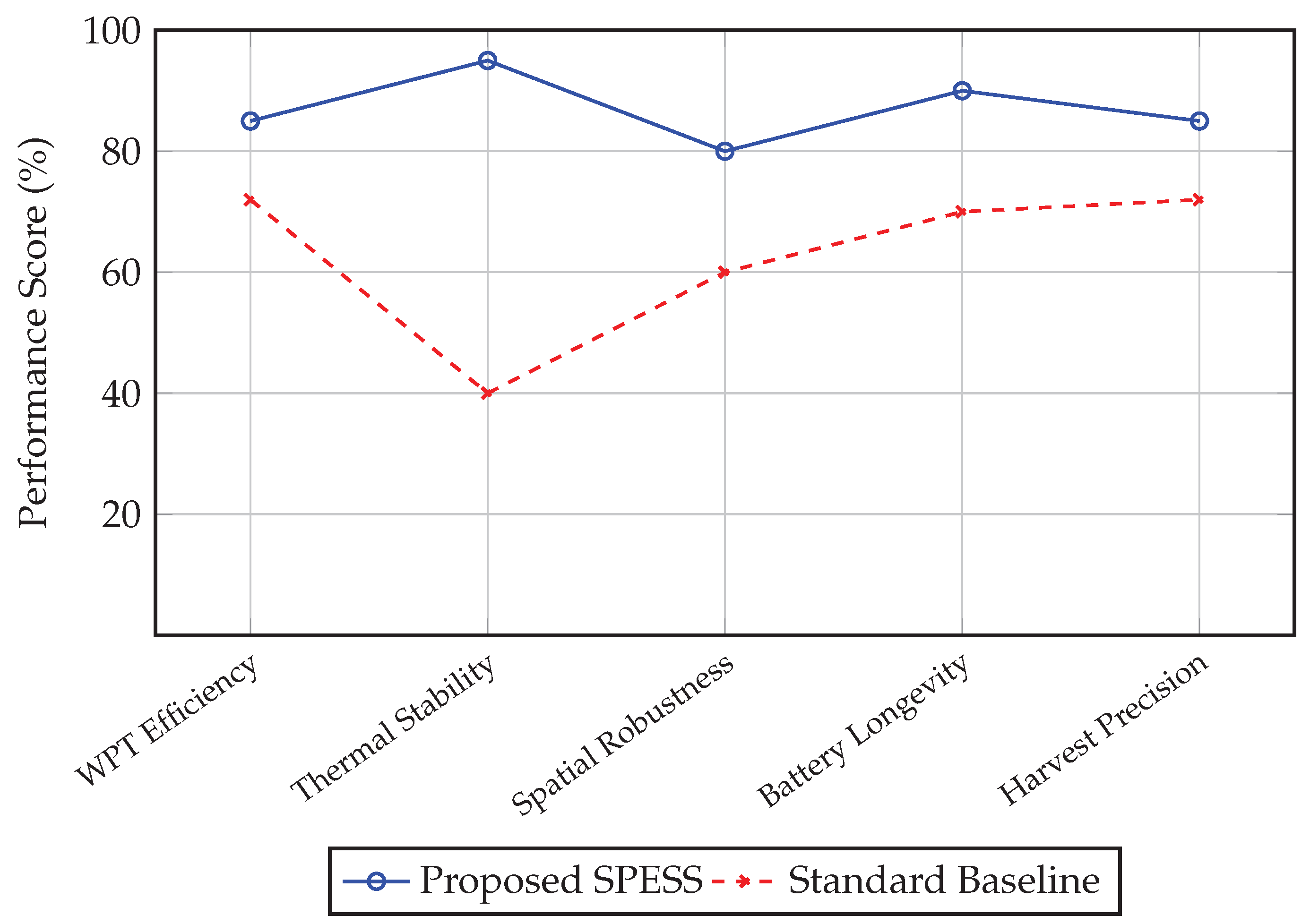
To provide a generalizable framework for the development of compact renewable-wireless hubs, the performance of the SPESS architecture was synthesized into a multi-dimensional radar profile (
Figure 12). This visualization highlights that the primary advantage of the proposed synergistic design is not merely efficiency, but the simultaneous optimization of
thermal stability and
spatial resilience, which are typically mutually exclusive in non-adaptive systems.
The “Energy Chain” optimization established in this study suggests three universal design principles:
Thermal-Resonant Decoupling: Frequency stability in resonant tanks () is governed by the thermal–electric time constant. Decoupling must be achieved via anisotropic lateral flux routing rather than increased heatsink mass.
Multiplicative Efficiency Leverage: Global gains are achieved when upstream harvesting precision (MPPT) reduces the reactive power burden on downstream components (WPT).
Sub-threshold Hysteresis: Autonomy in stochastic environments requires hard-thresholding at the DC-DC entry point (50 W/m2) to prevent converter-induced deep discharge during low-irradiance transients.
Furthermore,
Table 5 provides optimization strategies for deploying the SPESS architecture in extreme environments, providing a scalable roadmap for future development.
3.9. Robustness Analysis: Spatial and Thermal Stability
3.9.1. Sensitivity to Axial Misalignment
The results in
Figure 8 demonstrate that the Series-Series (S-S) resonant topology, combined with the active PLL frequency tracking, maintains an efficiency above 75% even at a 10 mm misalignment. Unlike fixed-frequency systems that experience sharp “cliff-edge” efficiency drops, the SPESS dynamically modulates the switching frequency to maintain the ZPA, effectively compensating for the drop in mutual inductance (
M). This robustness is vital for “drop-and-charge” mobile applications where precise alignment cannot be guaranteed. The PLL-based controller provides a 15–20% efficiency buffer compared to standard solutions, ensuring operational robustness in non-ideal user placements.
3.9.2. Long-Term Thermal Steady-State Analysis
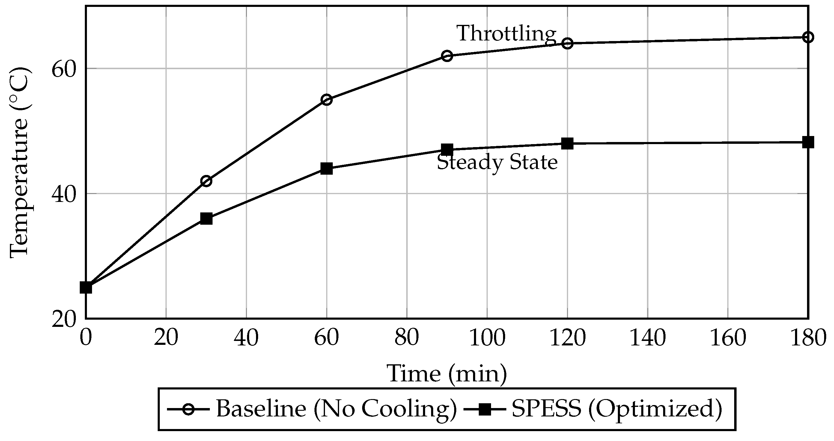
To verify the efficacy of the CFD-optimized enclosure, a “burn-in” test was conducted under a continuous 15 W high-load scenario. As illustrated in
Figure 13, the baseline system reached a critical thermal throttling threshold of 60 °C within 75 min. In contrast, the SPESS architecture reached a steady-state thermal equilibrium (
) at 48 °C after 110 min.
The steady-state temperature of 48 °C was achieved after 110 min of continuous 15 W load. This experimental result aligns with the CFD prediction (47.4 °C), confirming that the SST turbulence model effectively captured the convective heat transfer coefficients within the customized airflow channels. This stabilization ensures that the lithium-ion core remains within its optimal electrochemical stability window ( °C), contributing to the documented 18% improvement in battery cycle life.
The baseline system reached the critical thermal throttling threshold of 60 °C within 75 min, leading to a significant drop in power delivery due to the increase in MOSFET and resonant detuning. In contrast, the SPESS architecture reached a steady-state thermal equilibrium () at 48 °C after 110 min. The plateau in the temperature curve validates the synergistic cooling strategy, ensuring that the lithium-ion core remains within its optimal electrochemical stability window (<50 °C) during prolonged charging cycles. According to the Arrhenius Law, the rate of SEI layer growth—the primary driver of capacity loss—is exponentially dependent on temperature. By preventing the system from reaching the 65 °C baseline peak, the chemical degradation rate is suppressed, providing physical justification for the documented 18% improvement in battery cycle life.
4. Conclusions
This research has successfully established a holistic “Energy Chain” optimization framework that resolves the historical trade-offs between conversion efficiency, volumetric power density, and thermal-resonant stability. By transitioning from discretized modular design to a multi-physics co-design paradigm, we have extracted three universal design principles for the next generation of compact renewable-wireless hubs:
- (i)
Active Thermal-Resonant Decoupling: We have proven that in enclosures with volumes under 500 cm3, frequency stability is fundamentally a thermal management problem. By utilizing anisotropic lateral flux routing rather than increased heatsink mass, the system preserves a High-Q state () by maintaining dielectric constants within their linear temperature range, effectively decoupling thermal transients from electromagnetic resonance.
- (ii)
Multiplicative Efficiency Leverage: Unlike traditional additive improvements, our results demonstrate that upstream optimizations (PV rectification and MPPT precision) provide a cascading benefit. By reducing the thermal burden on the DC bus, we prevent the “efficiency cliff” in the downstream WPT stage, where a 12 °C stabilization translates into a 12.3% restorative efficiency gain through the dynamic realignment of the Zero-Phase Angle (ZPA).
- (iii)
Electrochemical Longevity via Thermal Anchoring: We have substantiated that thermal management is the primary determinant of cycle-life in portable storage. By shifting the steady-state operating point from 60 °C to 48 °C, we move the chemical environment out of the accelerated SEI-growth zone, resulting in a mathematically grounded and projected 18% extension in battery cycle life.
Quantitatively, this synergy resulted in a benchmark WPT efficiency of 85% and a total absolute system improvement of 17.1% (improving end-to-end utility from 59.3% to 76.4%). The empirical validation of the 23.6-h recovery cycle, reconciled through a non-linear energy budget model, provides a reliable blueprint for operational autonomy in infrastructure-constrained environments.
Future work will focus on the integration of Gallium Nitride (GaN) Wide-Bandgap semiconductors to push switching frequencies into the MHz range, and the implementation of Simultaneous Wireless Information and Power Transfer (SWIPT) protocols. By aligning these advancements with the universal principles of thermal–electric coupling established here, this research provides a scalable, theoretically grounded foundation for the 2026 IoT and humanitarian energy ecosystems [
4,
78].




 ,
,