Article

Design of Hybrid Cooling System for Thermal Management of Lithium-Ion Batteries Using Immersion Method with Nanofluid Supported Heat Pipes

Department of Mechanical Engineering, Karabuk University, 78600 Karabuk, Türkiye
*
Author to whom correspondence should be addressed.
Energies 2025, 18(8), 2123; https://doi.org/10.3390/en18082123
Submission received: 4 March 2025 / Revised: 25 March 2025 / Accepted: 9 April 2025 / Published: 21 April 2025
(This article belongs to the Section J1: Heat and Mass Transfer)

Abstract

:
In this study, straight and looped heat pipes were designed and manufactured, and their performance in cooling cylindrical lithium-ion batteries known as standard 18,650 batteries on the market was investigated. Pure water, methanol, and thermasolv IM2 liquid were used as working fluids in heat pipes. Nanofluid solutions were measured and prepared on a precision balance as 2% by weight according to the working fluid. These nanosolutions were injected into the heat pipes at a ratio of one-third by volume of the working fluids. In the designed experimental setup, the coils were placed 1 cm above the evaporator part of the heat pipes. Thanks to the designed electrical circuits, the amount of load given to and withdrawn from the batteries is controlled. The heated batteries evaporate the liquid in the heat pipe, the vapor rises and reaches the condenser. As a result of the evaporation, efficient heat transfer from the evaporator to the condenser takes place by transporting nanoparticles. At a certain flow rate, the refrigerant is transferred to the refrigerant as a result of the withdrawal of the refrigerant from the heat pipe. In this study, it is seen that the immersion method of the evaporator part in the pool full of IM2 liquid is repeated and the results are examined.

1. Introduction

Today, batteries are the most important energy storage unit that provides power to portable devices, tools, vehicles, and equipment. Lithium-ion batteries are highly preferred due to many positive aspects, such as increasing the power of the mentioned machines, and offering longer performance and reusability. Lithium-ion batteries stand out with their high capacity and reusability. When lithium-ion batteries are examined, it has been determined that a large amount of heat is generated inside the batteries and modules due to the electrochemical reaction heat and ohmic heat effect that occur during the charging and discharging processes [1]. Overheating in lithium-ion batteries significantly affects the service life of these batteries, and can also cause serious safety problems by causing thermal runaway on the batteries [2,3,4,5]. As a result of the development of fast charging technology and the continuous increase in battery energy density, it is seen that the overheating problem of lithium-ion batteries has become more serious than ever [6]. For this reason, in order to keep the temperature of the battery modules within the appropriate ranges, it is of great importance to apply thermal management to the batteries. While the maximum allowable temperature on the batteries should be in the range of 25–40 °C, the temperature change range here should be 5 °C [7,8]. Active cooling methods must be used to meet the safety requirements of lithium-ion batteries. There are many battery cooling technologies applied today. Some of these are air cooling, liquid cooling, phase-change material cooling, heat pipe cooling, thermoelectric system cooling, active cooling system cooling, immersion cooling, and hybrid cooling systems formed by combining at least two of these [9,10]. In this study, the cooling of battery cells with a hybrid cooling system designed together with heat pipes and the immersion method, which are increasingly being used in today’s increasingly widespread areas, can be designed in any size and are also known as passive cooling systems, is discussed.
Here, the evaporated fluid in the evaporator section of the heat pipe rises and passes to the condenser section, while the nanoparticles with very high heat capacity are carried along with it. The nanofluid that draws heat from the condenser section condenses again and returns to the evaporator section, providing very efficient heat transfer. The immersion method, which is a new approach, is the cooling of the battery packs in a pool containing a dielectric liquid. Since the liquid perfectly covers the battery packs and the boiling point of the selected liquid is within the operating temperature range, when the batteries start to heat up during charging and discharging, the liquid molecules surrounding the battery surface draw this heat away from the surface. Circulation is formed in the pool, and effective cooling is provided for the batteries. In this study, a hybrid cooling system was designed using heat pipes and immersion methods, both separately and together, and the advantages and disadvantages of these two systems were discussed.
With the developing technological devices in the world, overheating problems are on the agenda. Although heat pipes are sufficient to cope with these problems, the increasing energy demand and, therefore, the heating problems make it necessary to improve the performance of heat pipes. When the studies in the literature are examined, it is seen that the addition of nanoparticles to the base fluids of heat pipes increases the heat conduction of heat pipes. One of the important factors affecting the performance in heat pipes is thermal resistance. As a result of the evaporation of the liquid in the heat pipe with the heat it receives, bubbles are formed on the surface of the heat pipe. Since the bubbles prevent the liquid from contacting the surface, the thermal conductivity decreases, and the counter effect created by these bubbles is seen as thermal resistance [11]. Metallic nanoparticles added to the heat pipes prevent the formation of bubbles in the heat pipe. It has been determined that the bubbles formed here are burst by the metal particles. This contribution causes a significant decrease in thermal resistance [12,13]. The use of low-thermal-performance liquids in heat pipes both reduces the thermal performance capacity and causes the design to be in sizes that cover a lot of dimensions. It is seen that nanomaterial technology is integrated into the field of heat transfer in order to reduce thermal resistance and ensure design efficiency. Studies conducted since the 1990s have made significant contributions to the subject of heat transfer. Here, it is seen that nanomaterials in the base fluid reduce bubble formation and thus provide smaller sizes. As a result of reducing bubble formation, heat transfer increases and thermal resistance decreases accordingly. Here, the sizes of the particles mixed into the fluid also have an important effect in terms of efficiency. While negative effects are observed when particle sizes are a micron in diameter, it is observed that positive effects approach the maximum when particle sizes are reduced to particle sizes smaller than 100 nm.
Nelson et al. [14] thermally analyzed a 48-cell module with air cooling and immersion methods. As a result of the study, it was determined that, under the same load conditions, there was a 2.5 °C increase in the cell surface with the silicone oil immersion method compared with a 5.3 °C increase with air cooling, which was more efficient.
In the study by Wu et al. [15], the use of heat pipes to cool a cylindrical battery cell was experimentally investigated. It was determined that surface contact was very important to achieve high efficiency and an aluminum plate was placed due to its high conductivity and emissivity to improve the contact resistance between both the heat pipe and the cell. It was found that this design caused the temperature to drop from 45 °C to 38 °C.
In the study by Tsai et al. [16], a mixture of pure water and gold nanoparticles was prepared and heat pipes operating with pure water and pure water/gold nanoparticles were compared. Experimental data obtained from the heat pipes used indicated that the thermal resistance decreased by 33% in heat pipes using water as the fluid, and by 56% in nanosolutions using pure water-gold.
In the study by Qu et al. [17], it was investigated how the pulsating heat pipe (PHP) using SiO2/water nanofluid as the base fluid improved the thermal capacity of the system. The nanoparticle ratio in the prepared nanosolutions was selected as 0.6% by weight. It was determined that the decrease in thermal resistance was 25.7% less in the heat pipes using SiO2/water nanofluid compared with the heat pipes using pure water.
Ji et al. [18] investigated the thermal recovery effect of Al2O3 nanoparticle size in a pulsating heat pipe. Solutions consisting of particles with average diameters of 50 nm, 80 nm, 2.2 μm, and 20 μm were prepared and experiments were carried out. As a result, it could be seen that Al2O3 particle size greatly affects the heat transfer success of the vibrating heat pipe (PHP). Importantly, the reduction in particle size also contributes to the initiation of the pulsating motion.
In the study conducted by Rao et al. [19], an experiment was carried out to determine the temperature distribution of a battery when the input power varied between 10 W and 60 W. It was shown in the study that the highest battery surface temperature Tmax could be kept below 50 °C when the heat generation was less than 50 W and it was found that the temperature change (ΔT) was less than 5 °C when the heat generation was 30 W or less.
In the study by Wang et al. [20], the performance of heat pipes was investigated using a simulated heat source of 2.5 to 40 W/cell. It was observed that, when the heat generated by the battery cell was lower than 10 W/cell, the heat pipe was able to keep the temperature of this battery below 40 °C. In addition, it was determined that, when the battery produced heat in the range of 20–50 W/cell, the heat pipe was able to keep the surface temperature of the battery below 70 °C.
In the studies by Goshayeshi et al. [21,22,23] the effects of the magnetic field on heat pipes were investigated, and ferromagnetic nanofluid Fe2O3 was used. It was determined that the magnetic field effect in the pulsating heat pipe made of copper material caused an improvement of 2–3.1 °C in the surface temperatures of the evaporator region.
Heydarian et al. [24] used a mixture of water and paraffin nanocapsules at various concentrations as the working fluid in the pulsating heat pipe (PHP). As a result of the study, it was determined that it was possible to reduce the thermal resistance of PHP and increase the heat transfer rate by using nanocapsules. The use of this mixture reduced the thermal resistance of PHP by 44% at 50 W heat load. The addition of paraffin nanocapsules also expanded the working range of PHP. While the minimum thermal resistance of PHP was 0.86 KW−1 in the vertical position and at 50 W heat input, the highest thermal resistance, which means the lowest effective thermal conductivity, was 5.38 KW−1 when the inclination angle was equal to 30°.
In the study by Deng et al. [25], a 5-L-shaped heat pipe system was designed for a single battery cell. A 4.8 °C decrease in maximum temperature was detected at 100 A discharge under free convection conditions.
In the experimental study conducted by Cacua et al. [26], it was investigated how a gravity-assisted thermosyphon with a base fluid containing alumina-doped nanofluid affected the thermal resistance of the system. As a result, it was determined that there was a 24% improvement in thermal resistance in the nanofluid heat pipe system containing Al2O3/water.
Gomez et al. [27] used a working fluid containing Novec 7000 liquid/water in a closed-loop thermosyphon (heat pipe). The heat pipe was covered with an aluminum block. In the system used, due to the density of the heat pipe in the evaporator section, the Novec 7000 liquid in the lower part, the heat pipe in the condenser section, which starts to boil immediately due to its low boiling point, forms bubbles, and these bubbles mix with water to perform effective heat transfer. As a result of the experimental study, the system was able to keep the temperature below 70 °C in the aluminum block operating with a heat flux of 220 kW/m2 without any additional energy consumption. It shows that the effect of water in the condenser is effective in improving heat transfer and cooling liquid condensation. The heat transfer coefficients in the condenser are improved by 22% and 133%.
Mbulu et al. [28] designed a battery thermal management system with L- and I-shaped heat pipes. In this study, it was shown that the battery temperature can be kept below 55 °C, even when the heat generated from the battery is 60 W. When the heat input to the system was increased to 30 W, 40 W, 50 W, and 60 W, the battery surface temperatures were obtained as 43.82 °C, 46.59 °C, 50.96 °C, and 54.38 °C, respectively.
Arai and Kawaji [29] investigated the performance and flow relationships in heat pipe experiments using Novec 7000 fluid and found that pulsating flow provided the most effective PHP operation in the entire range of experimental conditions for 0.8 mm2 and 1.2 mm2 flow channels. It was observed that the pulsating flow was maintained at a constant level when the flow channel was 2 mm2 and the filling ratio was increased to 80% by volume. When the effective thermal conductivities obtained for different flow channel sizes at the same filling ratio were compared, the effective thermal conductivity of the 0.8 mm2 flow channel was calculated to be approximately 1/7 compared with the 2 mm2 channel.
Zeng et al. [30] applied a hybrid micro heat pipe array (MHPA) to the battery thermal management system (BTMS) of cylindrical batteries. Compared with a system without MHPA, the battery surface temperature (Tmax) decreased by 34.11% and the temperature change (ΔT) decreased from 3.66 °C to 0.66 °C at a 1C discharge rate. At a 3C discharge rate, Tmax and ΔT were found to decrease to 41.03 °C and 2.16 °C, respectively.
Today, heating problems in systems that require excessive power, such as very fast CPUs (computer processors), various computer hardware, cloud technology, and electric vehicles, are increasing in parallel with the point that technology has reached. Therefore, the modernization of heat pipes, which play an important role in cooling these systems, is essential. Scientists have proposed the immersion method as a new method. This method involves applying the system into this liquid using a liquid and dielectric material whose boiling point is suitable for the operating temperature. For this reason, the necessity of conducting this study has arisen.

2. Method

The straight and pulsating heat pipes designed in the experimental setup were applied to the battery packs and the amount of heat extracted from the battery pack was determined by thermocouples. In this study, liquid cooling was applied in the condenser section, the flow rate and temperature differences of the cooling water were calculated, and the thermal performances of the heat pipes were analyzed. The temperature, current, and voltage passing through the battery during charging and discharging were measured and both thermal and capacity efficiency were compared. Experiments were carried out using 2 wt% doped nanofluids with water/CuO, methanol/CuO, water/Al2O3, and methanol/Al2O3. All experiments were repeated in a pool completely filled with Thermasolv IM2 dielectric fluid using the battery pack immersion method. As a result of the experiments, hybrid cooling designs with a straight heat pipe, pulsating heat pipe, and the immersion method were compared with each other. Here, the cooling water is constant at ambient temperature (20 °C) and a flow rate of 18 L/h for all systems. A schematic view of the experimental setup is shown in Figure 1.

Findings

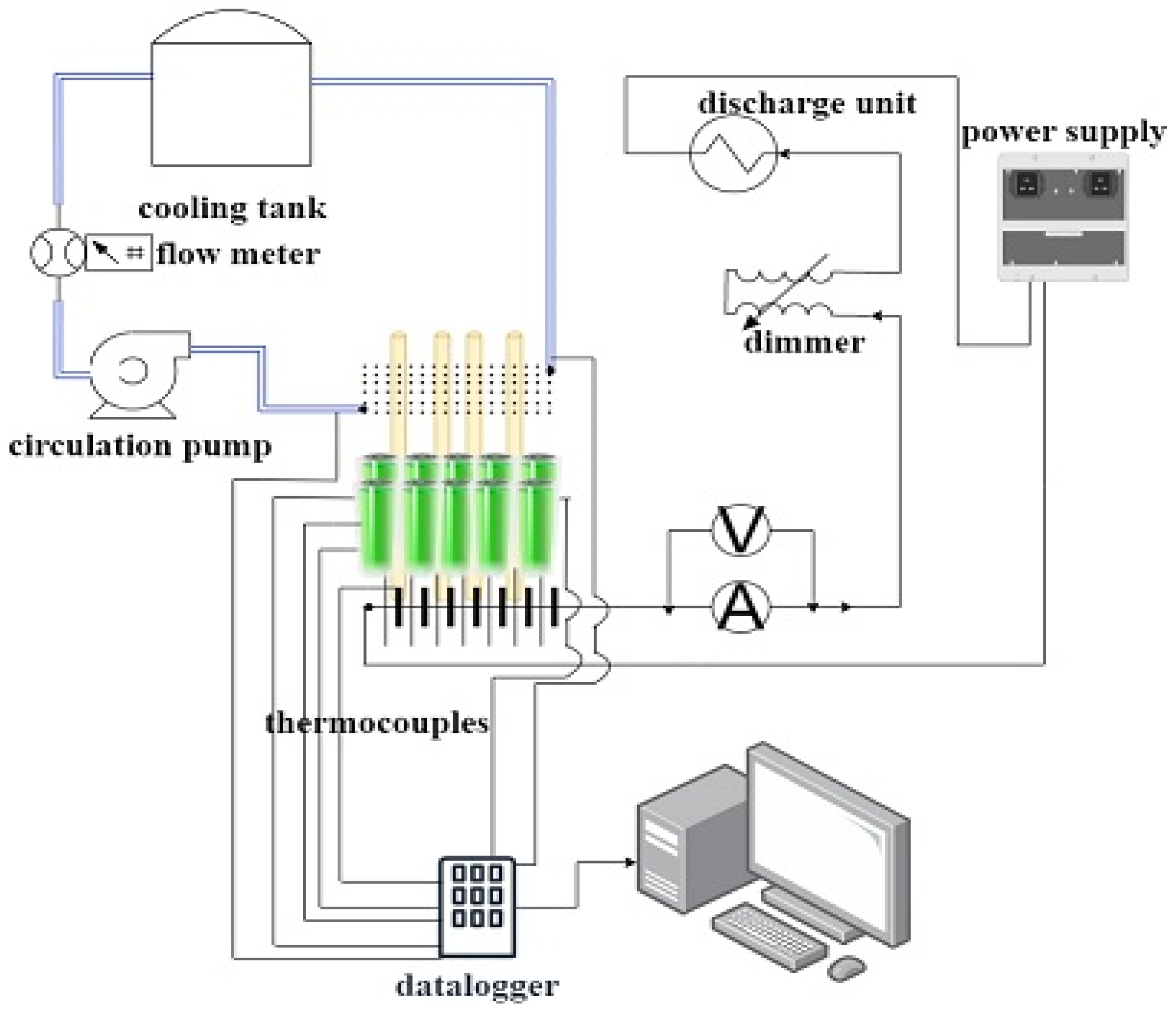
In this study, we aimed to keep the battery packs consisting of 24 cells at different current intensities (1C, 2C, and 3C) in the optimum operating range of 15–40 °C with straight heat pipe, pulsating heat pipe, immersion method, and heat pipe immersion method hybrid cooling systems. The experimental studies were compared with each other by percentage efficiency calculation.
ƞ = T h T l T h 100
In Table 1 and 
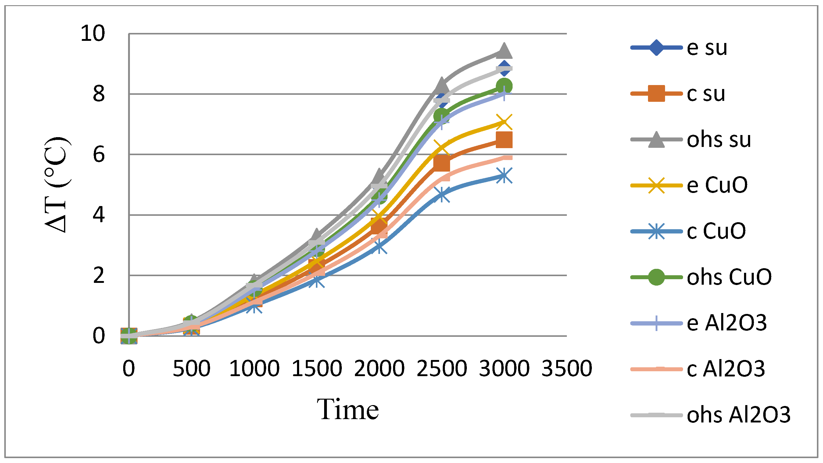
Figure 2, the experiments carried out in the straight heat pipe system are compared.
CuO nanofluid-doped heat pipes were 13.25% more efficient than pure water in reducing the average cell temperature and 7.22% more efficient than Al2O3-doped heat pipes.
In Table 2 and 
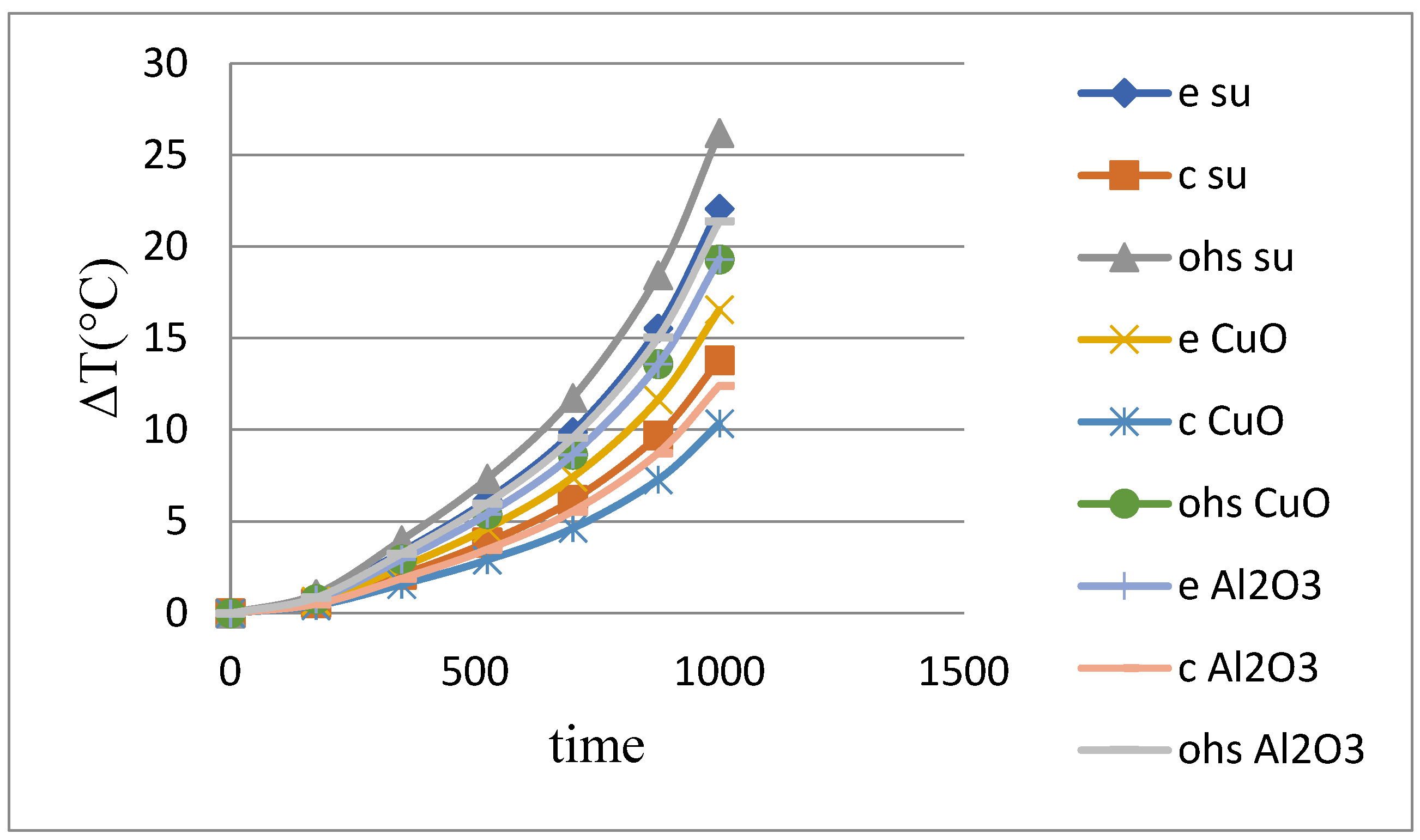
Figure 3, the experiments performed in the straight heat pipe system are compared.
CuO nanofluid-doped heat pipes were 28.41% more efficient than pure water in reducing the average cell temperature and 13.1% more efficient than Al2O3 nanoparticle-doped heat pipes.
In Table 3 and Figure 4, the experiments performed in the straight heat pipe system are compared.
CuO nanofluid-doped heat pipes provided 26.33% efficiency in reducing the average cell temperature compared with pure water, while their efficiency was 9.81% compared with Al2O3-doped heat pipes.
The most successful results in reducing the average cell temperature in plain heat pipe experiments occurred under 2C current intensity and in experiments with CuO-doped nanofluids. The reason for the low efficiency at 1C current intensity is that the heat pipe cannot reach the optimum operating temperature.
The reason why the time scales in the graphs were t = 3000 s at 1C current intensity, t = 1500 s at 2C current intensity, and t = 1000 s at 3C current intensity was that they are the preferred times in order to not consume the total energy of the batteries depending on the current speed and not to reach the cut-off voltage. When lithium-ion batteries are completely discharged, the life of the batteries decreases and may pose a risk of explosion in terms of safety. Therefore, it is important to use lithium-ion batteries within safe limits without completely discharging them. Under normal conditions, the 1C current rate refers to the discharge rate of the battery in exactly 1 h and is 3600 s. Likewise, half an hour for 2C is 1800 s, and for 3C, it is one-third of 1 h, i.e., 1200 s. In order to eliminate the risk of non-rechargeability and explosion if the lithium-ion batteries are completely discharged by exceeding the cut-off voltage, these times were selected as 50 min (3000 s) for 1C, 25 min (1500 s) for 2C, and 16.7 min (1000 s) for 3C.
As shown in Table 4 and Figure 5, the experiments performed in the straight heat pipe system using methanol-based fluid are compared.
CuO nanofluid doped heat pipes were 12.87% more efficient than methanol in reducing the average cell temperature and 6.38% more efficient than Al2O3 doped heat pipes.
As shown in Table 5 and Figure 6, the experiments performed in the straight heat pipe system using methanol-based fluid are compared.
CuO nanofluid-doped heat pipes were 28.28% more efficient than methanol in reducing the average cell temperature, while Al2O3-doped heat pipes were 12.88% more efficient.
As shown in Table 6 and Figure 7, the experiments performed in the straight heat pipe system using methanol-based fluid are compared.
CuO nanofluid-doped heat pipes were 26.14% more efficient than methanol in reducing the average cell temperature, while Al2O3-doped heat pipes were 11.02% more efficient.
As shown in Table 7 and Figure 8, the experiments performed in the straight heat pipe system using water-based fluid are compared.
CuO nanofluid-doped heat pipes were 19.54% more efficient than water in reducing the average cell temperature, while Al2O3-doped heat pipes were 10.26% more efficient than water.
As shown in Table 8 and Figure 9, the experiments performed in the pulsating heat pipe system using water-based fluid are compared.
CuO nanofluid-doped heat pipes were 29.26% more efficient than water in reducing the average cell temperature, while Al2O3-doped heat pipes were 13.91% more efficient than water.
As shown in Table 9 and Figure 10, the experiments performed in the pulsating heat pipe system using water-based fluid are compared.
CuO nanofluid-doped heat pipes were 25.53% more efficient than water in reducing the average cell temperature, while Al2O3-doped heat pipes were 9.68% more efficient.
As can be seen in Table 10 and Figure 11, pulsating heat using methanol-based fluid experiments performed in the tubular system are compared.
CuO nanofluid-doped heat pipes were 13.3% more efficient than water in reducing the average cell temperature and 7.14% more efficient than Al2O3-doped heat pipes.
As shown in Table 11 and Figure 12, the experiments performed in the pulsating heat pipe system using methanol-based fluid are compared.
CuO nanofluid-doped heat pipes provide 28.74% efficiency compared with water in reducing the average cell temperature, while it is 13.14% efficient compared with Al2O3 doped heat pipes.
As shown in Table 12 and Figure 13, the experiments performed in the pulsating heat pipe system using methanol-based fluid are compared.
CuO nanofluid-doped heat pipes provide 26.14% efficiency compared with water in reducing the average cell temperature, while it is 23.03% efficient compared with Al2O3-doped heat pipes.
In the experiments using the immersion method, the battery cells were placed in the Thermasolv im2 liquid pool and the results were tested. Although the immersion method alone provides successful cooling, heat pipe-reinforced systems provide important contributions at high current capacities.
As can be seen in Figure 14, in the study carried out only with the immersion method, temperature differences of 3.6 °C, 6.1 °C, and 8.7 °C at 2C current intensity and 8.7 °C at 3C current intensity were determined at the pool temperature under 1C current intensity. Here, the pool temperature is equal to the evaporator temperature as well as the average cell temperature, since the coils are completely inside the pool.
When the immersion method and heat pipe systems were combined and a hybrid thermal management design was created, as shown in Figure 15, it can be seen that the evaporator temperature difference (e) in the studies carried out with the pulsating heat pipe with water-based fluid (im2 php water) at 1C current intensity was 2.5 °C and the evaporator temperature difference (e) in the studies carried out with the pulsating heat pipe with water/CuO nanosolution base fluid (im2 php water/CuO) was 1, an evaporator temperature difference (e) of 2 °C was determined in the studies carried out with a pulsating heat pipe (im2 php water/Al2O3) with 9 °C water/Al2O3 nanosolution-based fluid.
The evaporator temperature difference (e) was 2.6 °C in studies with methanol-based fluidized pulsating heat pipe (im2 php methanol); the evaporator temperature difference (e) was 2.6 °C in studies with methanol/CuO nanosolution-based fluidized pulsating heat pipe (im2 php methanol/CuO), and the evaporator temperature difference (e) was determined as 2.3 °C in the studies carried out with the pulsating heat pipe (im2 php methanol/Al2O3) at 3 °C with methanol/Al2O3 nanosolution-based fluid. The most successful system was the im2 php water/CuO hybrid design with 47.22% efficiency compared with the immersion method.
Figure 16 shows that the evaporator temperature difference (e) in the studies carried out with the water-based fluid pulsating heat pipe (im2 php water) at 2C current intensity was 3.8 °C and the evaporator temperature difference (e) in the studies carried out with the water/CuO nanosolution-based fluid pulsating heat pipe (im2 php water/CuO) was 3.8 °C and 2 °C, and for the water/Al2O3 nanosolution-based fluid pulsating heat pipe (im2 php water/Al2O3), an evaporator temperature difference (e) of 3.4 °C was determined.
The evaporator temperature difference (e) was 4 °C in the studies carried out with the methanol-based fluidized pulsating heat pipe (im2 php methanol), the evaporator temperature difference (e) was 3.4 °C in the studies carried out with the methanol/CuO nanosolution-based fluidized pulsating heat pipe (im2 php methanol/CuO), and the evaporator temperature difference (e) was 3.7 °C in the studies carried out with the methanol/Al2O3 nanosolution-based fluidized pulsating heat pipe (im2 php methanol/Al2O3).
Here, the most successful system was im2 php water/CuO hybrid design with 47.54% efficiency compared with the immersion method.
Figure 17 shows that the evaporator temperature difference (e) in the studies carried out with the pulsating heat pipe with water-based fluid (im2 php water) at 3C current intensity was 6 °C, the evaporator temperature difference (e) in the studies carried out with the pulsating heat pipe with water/CuO nanosolution-based fluid (im2 php water/CuO) was 4 °C, and the evaporator temperature difference (e) for the water/Al2O3 nanosolution base fluid pulsating heat pipe (im2 php water/Al2O3) was 5 °C.
The evaporator temperature difference (e) was 6.4 °C in studies with a methanol-based fluidized pulsating heat pipe (im2 php methanol), the evaporator temperature difference (e) was 4.4 °C in studies with a methanol/CuO nanosolution-based fluidized pulsating heat pipe (im2 php methanol/CuO), and the evaporator temperature difference (e) was found to be 5.3 °C in the studies carried out with the pulsating heat pipe (im2 php methanol/Al2O3) with 6 °C methanol/Al2O3 nanosolution-based fluid. Here, the most successful system was the im2 php water/CuO hybrid design with 49.43% efficiency compared with the immersion method.
In the study, uncertainty analysis was performed and the results were examined.
S: Measured dimension
X1, X2,…, Xn: Variables affecting measurement
W1, W2,…, Wn: The error rate of the independent variable is;
Total error rate WR;
WS = [(∂S/(∂x1)w1)2 + (∂S/(∂x2)w2)2 + (∂S/(∂x3)w3)2 + (∂S/(∂x4)w4)2 + ⋯ + (∂S/(∂xn)wn)2
Or
WS = S[((Wx1)/x1)2 + ((Wx2)/x2)2 + ((Wx3)/x3)2 + ((Wx4)/x4)2 + ⋯ + ((Wxn)/xn)2
The total uncertainty in our experiment was calculated using the uncertainty analysis formulas and/or equations mentioned above according to the measurement accuracy rates shown in Table 13. The total error rate was calculated as Ws = ±7.418 and was considered acceptable.

3. Conclusions

In the studies carried out with the hybrid thermal management system formed by the immersion method and pulsating heat pipe, a high level of thermal management efficiency was obtained in comparison with all other cooling methods.
It has been observed that the immersion method provides a homogeneous change in the surface temperatures of all cells in the battery pack, which will increase both the power balance of the battery and the life of the system.
Battery surface temperatures reaching up to 30.6 °C at 3C current intensity against heat pipes with very good cooling systems can be improved up to 4.4 °C with the most efficient hybrid cooling system designed. This corresponds to an efficiency of approximately 20.2 °C Therefore, it can be said that, in the near-future, the immersion method and heat pipe hybrid systems will be an inevitable approach in human life in the cooling of batteries and electronic devices.
All cooling systems designed in this study were able to keep the battery packs consisting of 24 cells within the optimum operating temperature range of 15–40 °C.
The measured experimental error margin was calculated to be at reasonable levels (Ws = ±7.418).

Author Contributions

Conceptualization, O.M. and M.Ö.; Methodology, O.M. and M.Ö.; Validation, M.Ö.; Formal analysis, M.Ö.; Investigation, M.Ö.; Resources, O.M.; Data curation, O.M.; Writing—original draft, O.M.; Writing—review & editing, O.M.; Visualization, O.M.; Supervision, M.Ö.; Project administration, O.M. and M.Ö. All authors have read and agreed to the published version of the manuscript.

Funding

This research received no external funding.

Data Availability Statement

The original contributions presented in this study are included in the article. Further inquiries can be directed to the corresponding author.

Conflicts of Interest

The authors declare no conflict of interest.

References

  1. Abdelkareem, M.A.; Maghrabie, H.M.; Abo-Khalil, A.G.; Adhari, O.H.K.; Sayed, E.T.; Radwan, A.; Elsaid, K.; Wilberforce, T.; Olabi, A.G. Battery thermal management systems based on nanofluids for electric vehicles. J. Energy Storage 2022, 50, 104385. [Google Scholar] [CrossRef]
  2. Kong, D.; Lv, H.; Ping, P.; Wang, G. A review of early warning methods of thermal runaway of lithium ion batteries. J. Energy Storage 2023, 64, 107073. [Google Scholar] [CrossRef]
  3. Rezk, H.; Sayed, E.T.; Maghrabie, H.M.; Abdelkareem, M.A.; Ghoniem, R.M.; Olabi, A.G. Fuzzy modelling and metaheuristic to minimize the temperature of lithium-ion battery for the application in electric vehicles. J. Energy Storage 2022, 50, 104552. [Google Scholar] [CrossRef]
  4. Wang, Q.; Ping, P.; Zhao, X.; Chu, G.; Sun, J.; Chen, C. Thermal runaway caused fire and explosion of lithium ion battery. J. Power Sources 2012, 208, 210–224. [Google Scholar] [CrossRef]
  5. Wang, H.; Lara-Curzio, E.; Rule, E.T.; Winchester, C.S. Mechanical abuse simulation and thermal runaway risks of large-format Li-ion batteries. J. Power Sources 2017, 342, 913–920. [Google Scholar] [CrossRef]
  6. Kumar Thakur, A.; Sathyamurthy, R.; Velraj, R.; Saidur, R.; Pandey, A.K.; Ma, Z.; Singh, P.; Hazra, S.K.; Sharshir, S.W.; Prabakaran, R.; et al. A state-of-the art review on advancing battery thermal management systems for fast-charging. Appl. Therm. Eng. 2023, 226, 120303. [Google Scholar] [CrossRef]
  7. Lu, L.; Han, X.; Li, J.; Hua, J.; Ouyang, M. A review on the key issues for lithium-ion battery management in electric vehicles. J. Power Sources 2013, 226, 272–288. [Google Scholar] [CrossRef]
  8. Lv, Y.; Yang, X.; Li, X.; Zhang, G.; Wang, Z.; Yang, C. Experimental study on a novel battery thermal management technology based on low density polyethylene-enhanced composite phase change materials coupled with low fins. Appl. Energy 2016, 178, 376–382. [Google Scholar] [CrossRef]
  9. Fan, L.; Khodadadi, J.M.; Pesaran, A.A. A parametric study on thermal management of an air-cooled lithium-ion battery module for plug-in hybrid electric vehicles. J. Power Sources 2013, 238, 301–312. [Google Scholar] [CrossRef]
  10. Mahamud, R.; Park, C. Reciprocating air flow for Li-ion battery thermal management to improve temperature uniformity. J. Power Sources 2011, 196, 5685–5696. [Google Scholar] [CrossRef]
  11. Huminic, G.; Huminic, A.; Morjan, I.; Dumitrache, F. Experimental Study of The Thermal Performance of Thermosyphon Heat Pipe Using Iron Oxide Nanoparticles. Int. J. Heat Mass Transf. 2011, 54, 656–661. [Google Scholar] [CrossRef]
  12. Sureshkumar, R.; Mohideen, S.T.; Nethaji, N. Heat transfer characteristics of nanofluids in heat pipes: A review. Renew. Sustain. Energy Rev. 2013, 20, 397–410. [Google Scholar] [CrossRef]
  13. Şahin, B.; Çomaklı, K.; Çomaklı, Ö.; Yılmaz, M.; Karslı, S.; Özyurt, Ö.; Karagöz, Ş.; Kaya, M. Investigation of Heat Transfer and Flow Characteristics of Nanofluids; Project No: 105M292; Tübitak: Ankara, Türkiye, 2010. [Google Scholar]
  14. Nelson, P.; Dees, D.; Amine, K.; Henriksen, G. Modeling thermal management of lithium-ion PNGV batteries. J. Power Sources 2002, 110, 349–356. [Google Scholar] [CrossRef]
  15. Wu, W.; Wang, S.; Wu, W.; Chen, K.; Hong, S.; Lai, Y. A critical review of battery thermal performance and liquid based battery thermal management. Energy Convers. Manag. 2019, 182, 262–281. [Google Scholar] [CrossRef]
  16. Tsai, C.Y.; Chien, H.T.; Ding, P.P.; Chan, B.; Luh, T.Y.; Chen, P.H. Effect of structural character of gold nanoparticles in nanofluid on heat pipe thermal performance. Mater. Lett. 2004, 58, 1461–1465. [Google Scholar] [CrossRef]
  17. Qu, J.; Wu, H. Thermal performance comparison of oscillating heat pipes with SiO2/water and Al2O3/water nanofluids. Int. J. Therm. Sci. 2011, 50, 1954–1962. [Google Scholar] [CrossRef]
  18. Ji, Y.; Ma, H.; Su, F.; Wang, G. Particle size effect on heat transfer performance in an oscillating heat pipe. Exp. Therm. Fluid Sci. 2011, 35, 724–727. [Google Scholar] [CrossRef]
  19. Rao, Z.; Wang, S.; Wu, M.; Lin, Z.; Li, F. Experimental investigation on thermal management of electric vehicle battery with heat pipe. Energy Convers. Manag. 2013, 65, 92–97. [Google Scholar] [CrossRef]
  20. Wang, Q.; Jiang, B.; Xue, Q.F.; Sun, H.L.; Li, B.; Zou, H.M.; Yan, Y.Y. Experimental investigation on EV battery cooling and heating by heat pipes. Appl. Therm. Eng. 2014, 88, 54–60. [Google Scholar] [CrossRef]
  21. Goshayeshi, H.R.; Goodarzi, M.; Dahari, M. Effect of magnetic field on the heat transfer rate of kerosene/Fe2O3 nanofluid in a copper oscillating heat pipe. Exp. Therm. Fluid Sci. 2015, 68, 663–668. [Google Scholar] [CrossRef]
  22. Goshayeshi, H.R.; Safaei, M.R.; Goodarzi, M.; Dahari, M. Particle size and type effects on heat transfer enhancement of Ferro-nanofluids in a pulsating heat pipe. Powder Technol. 2016, 301, 1218–1226. [Google Scholar] [CrossRef]
  23. Goshayeshi, H.R.; Goodarzi, M.; Safaei, M.R.; Dahari, M. Experimental study on the effect of inclination angle on heat transfer enhancement of a ferrofluid in a closed loop oscillating heat pipe under magnetic field. Exp. Therm. Fluid Sci. 2016, 74, 265–270. [Google Scholar] [CrossRef]
  24. Heydarian, R.; Shafii, M.B.; Rezaee Shirin-Abadi, A.; Ghasempour, R.; Alhuyi Nazari, M. Experimental investigation of paraffin nano-encapsulated phase change material on heat transfer enhancement of pulsating heat pipe. J. Therm. Anal. Calorim. 2019, 137, 1603–1613. [Google Scholar] [CrossRef]
  25. Deng, S.; Li, K.; Xie, Y.; Wu, C.; Wang, P.; Yu, M.; Li, B.; Zheng, J. Heat pipe thermal management based on high-rate discharge and pulse cycle tests for lithium-ion batteries. Energies 2019, 12, 3143. [Google Scholar] [CrossRef]
  26. Cacua, K.; Buitrago-Sierra, R.; Pabón, E.; Gallego, A.; Zapata, C.; Herrera, B. Nanofluids stability effect on a thermosyphon thermal performance. Int. J. Therm. Sci. 2020, 153, 106347. [Google Scholar] [CrossRef]
  27. Gómez, M.A.; Bellas, R.; González-Gil, A.; Cacabelos, A.; Larrañaga, A. Thermal study of a passive cooling device operating through a bubble lifting CLTPT of NOVEC 7000 with a two-fluid condenser. Int. J. Heat Mass Transf. 2021, 177, 121530. [Google Scholar] [CrossRef]
  28. Mbulu, H.; Laoonual, Y.; Wongwises, S. Experimental study on the thermal performance of a battery thermal management system using heat pipes. Case Stud. Therm. Eng. 2021, 26, 101029. [Google Scholar] [CrossRef]
  29. Arai, T.; Kawaji, M. Thermal performance and flow characteristics in additive manufactured polycarbonate pulsating heat pipes with Novec 7000. Appl. Therm. Eng. 2021, 197, 117273. [Google Scholar] [CrossRef]
  30. Zeng, W.; Niu, Y.; Li, S.; Hu, S.; Mao, B.; Zhang, Y. Cooling performance and optimization of a new hybrid thermal management system of cylindrical battery. Appl. Therm. Eng. 2022, 217, 119171. [Google Scholar] [CrossRef]
Figure 1. Schematic experimental set-up.
Energies 18 02123 g001
Figure 2. Surface temperatures for 1C flow intensity, flat heat pipe system with water-based fluid.
Energies 18 02123 g002
Figure 3. Surface temperatures for 2C flow intensity, flat heat pipe system with water-based fluid.
Energies 18 02123 g003
Figure 4. Surface temperatures for 3C flow intensity, flat heat pipe system with water-based fluid.
Energies 18 02123 g004
Figure 5. Surface temperatures for 1C current intensity, straight heat pipe system with methanol-based fluid.
Energies 18 02123 g005
Figure 6. Surface temperatures for a 2C flow intensity, straight heat pipe methanol-based flow system.
Energies 18 02123 g006
Figure 7. Surface temperatures for the system with 3C flow intensity, methanol-based flow with a straight heat pipe.
Energies 18 02123 g007
Figure 8. Surface temperatures for the system with 1C flow intensity, water-based flow with pulsating heat pipe.
Energies 18 02123 g008
Figure 9. Surface temperatures for the system with 2C flow intensity, water-based flow with pulsating heat pipe.
Energies 18 02123 g009
Figure 10. Surface temperatures for the system with 3C flow intensity, water-based flow with pulsating heat pipe.
Energies 18 02123 g010
Figure 11. Surface temperatures for 1C current strength, pulsating heat pipe system with methanol-based flow.
Energies 18 02123 g011
Figure 12. Surface temperatures for 2C flow intensity, pulsating heat pipe system with methanol-based flow.
Energies 18 02123 g012
Figure 13. Surface temperatures for the system with 3C flow intensity, methanol-based flow with pulsating heat pipe.
Energies 18 02123 g013
Figure 14. Average cell surface temperatures in Thermasolv im2 immersion pool.
Energies 18 02123 g014
Figure 15. Surface temperatures of immersion method and PHP hybrid system under 1C current intensity.
Energies 18 02123 g015
Figure 16. Immersion method and hybrid system surface temperatures under 2C current intensity.
Energies 18 02123 g016
Figure 17. Immersion method and hybrid system surface temperatures under 3C current intensity.
Energies 18 02123 g017
Table 1. Comparison of the experiments performed in the flat heat pipe system (1C).
ExperimentEvaporator TemperatureCondenser TemperatureAverage Cell Temperature
Experiment using pure water at 1C current strength and t = 3000 s8.8 °C (e water)6.5 °C (c water)9.4 °C (ohs water)
Experiment using CuO doped nanofluids7.1 °C (e CuO)5.3 °C (c CuO)8.3 °C (ohs CuO)
Experiment using Al2O3 doped nanofluids8 °C (e Al2O3)5.9 °C (c Al2O3)8.9 °C (ohs Al2O3)
Table 2. Comparison of the experiments performed in the flat heat pipe system (2C).
ExperimentEvaporator TemperatureCondenser TemperatureAverage Cell Temperature
Experiment using pure water at 2C current strength and t = 1500 s16.4 °C (e water)8.8 °C (c water)17.6 °C (ohs water)
Experiment using water/CuO-doped nanofluids10 °C (e CuO)6.9 °C (c CuO)12.6 °C (ohs CuO)
Experiment using water/Al2O3-doped nanofluids12.1 °C (e Al2O3)7.8 °C (c Al2O3)14.5 °C (ohs Al2O3)
Table 3. Comparison of the experiments performed in the flat heat pipe system (3C).
ExperimentEvaporator TemperatureCondenser TemperatureAverage Cell Temperature
Experiment using pure water at 3C current strength and t = 1000 s22.1 °C (e water)13.8 °C (c water)26.2 °C (ohs water)
Experiment using CuO-doped nanofluids16.6 °C (e CuO)10.35 °C (c CuO)19.3 °C (ohs CuO)
Experiment using Al2O3-doped nanofluids19.3 °C (e Al2O3)12.4 °C (c Al2O3)21.4 °C (ohs Al2O3)
Table 4. Table of surface temperatures for a methanol-based flow system with a straight heat pipe (1C).
ExperimentEvaporator TemperatureCondenser TemperatureAverage Cell Temperature
Experiment using methanol at a current strength of 1C and t = 3000 s9.4 °C (e methanol)6.9 °C (c methanol)10.1 °C (ohs methanol)
Experiment using CuO-doped nanofluids7.5 °C (e CuO)5.7 °C (c CuO)8.8 °C (ohs CuO)
Experiment using Al2O3-doped nanofluids8.5 °C (e Al2O3)6.3 °C (c Al2O3)9.4 °C (ohs Al2O3)
Table 5. Table of surface temperatures for a methanol-based flow system with a straight heat pipe (2C).
ExperimentEvaporator TemperatureCondenser TemperatureAverage Cell Temperature
Experiment using methanol at a current strength of 2C and t = 1500 s18.4 °C (e methanol)9.9 °C (c methanol)19.8 °C (ohs methanol)
Experiment using CuO-doped nanofluids11.3 °C (e CuO)7.8 °C (c CuO)14.2 °C (ohs CuO)
Experiment using Al2O3-doped nanofluids13.6 °C (e Al2O3)8.8 °C (c Al2O3)16.3 °C (ohs Al2O3)
Table 6. Table of surface temperatures for a methanol-based flow system with a straight heat pipe (3C).
ExperimentEvaporator TemperatureCondenser TemperatureAverage Cell Temperature
Experiment using methanol at a current strength of 3C and t = 1000 s25.8 °C (e methanol)16.1 °C (c methanol)30.6 °C (ohs methanol)
Experiment using CuO-doped nanofluids19.3 °C (e CuO)12.1 °C (c CuO)22.6 °C (ohs CuO)
Experiment using Al2O3-doped nanofluids22.1 °C (e Al2O3)14.5 °C (c Al2O3)25.4 °C (ohs Al2O3)
Table 7. Table of surface temperatures for water-based flow system with a straight heat pipe (1C).
ExperimentEvaporator TemperatureCondenser TemperatureAverage Cell Temperature
Experiment using water at a current strength of 1C and t = 3000 s7.5 °C (e water)5.5 °C (c water)8.7 °C (ohs water)
Experiment using CuO-doped nanofluids6 °C (e CuO)4.5 °C (c CuO)7 °C (ohs CuO)
Experiment using Al2O3-doped nanofluids6.6 °C (e Al2O3)5 °C (c Al2O3)7.8 °C (ohs Al2O3)
Table 8. Table of surface temperatures for water-based flow system with a straight heat pipe (2C).
ExperimentEvaporator TemperatureCondenser TemperatureAverage Cell Temperature
Experiment using water at a current strength of 2C and t = 1500 s12 °C (e water)7 °C (c water)14 °C (ohs water)
Experiment using CuO-doped nanofluids8 °C (e CuO)5.5 °C (c CuO)9.9 °C (ohs CuO)
Experiment using Al2O3-doped nanofluids9.6 °C (e Al2O3)6.2 °C (c Al2O3)11.5 °C (ohs Al2O3)
Table 9. Table of surface temperatures for water-based flow system with a straight heat pipe (3C).
ExperimentEvaporator TemperatureCondenser TemperatureAverage Cell Temperature
Experiment using water at a current strength of 3C and t = 1000 s16.1 °C (e water)10 °C (c water)18.8 °C (ohs water)
Experiment using CuO-doped nanofluids12 °C (e CuO)7.5 °C (c CuO)14 °C (ohs CuO)
Experiment using Al2O3-doped nanofluids13.4 °C (e Al2O3)8.6 °C (c Al2O3)15.5 °C (ohs Al2O3)
Table 10. Table of surface temperatures for a methanol-based flow system with a straight heat pipe (1C).
ExperimentEvaporator TemperatureCondenser TemperatureAverage Cell Temperature
Experiment using methanol at a current strength of 1C and t = 3000 s8.4 °C (e methanol)6.2 °C (c methanol)9 °C (ohs methanol)
Experiment using CuO-doped nanofluids6.7 °C (e CuO)5.1 °C (c CuO)7.8 °C (ohs CuO)
Experiment using Al2O3-doped nanofluids7.6 °C (e Al2O3)5.6 °C (c Al2O3)8.4 °C (ohs Al2O3)
Table 11. Table of surface temperatures for a methanol-based flow system with a straight heat pipe (2C).
ExperimentEvaporator TemperatureCondenser TemperatureAverage Cell Temperature
Experiment using methanol at a current strength of 2C and t = 1500 s15.5 °C (e methanol)8.3 °C (c methanol)16.7 °C (ohs methanol)
Experiment using CuO-doped nanofluids9.5 °C (e CuO)6.5 °C (c CuO)11.9 °C (ohs CuO)
Experiment using Al2O3-doped nanofluids11.4 °C (e Al2O3)7.4 °C (c Al2O3)13.7 °C (ohs Al2O3)
Table 12. Table of surface temperatures for a methanol-based flow system with a straight heat pipe (3C).
ExperimentEvaporator TemperatureCondenser TemperatureAverage Cell Temperature
Experiment using methanol at a current strength of 3C and t = 1000 s20.3 °C (e methanol)12.7 °C (c methanol)24.1 °C (ohs methanol)
Experiment using CuO-doped nanofluids11.4 °C (e CuO)7.4 °C (c CuO)13.7 °C (ohs CuO)
Experiment using Al2O3-doped nanofluids15.2 °C (e Al2O3)9.5 °C (c Al2O3)17.8 °C (ohs Al2O3)
Table 13. Accuracy rate of equipment.
EquipmentMeasurement Accuracy Rate
Wattmeter±%1
Dimmer±%2
Flowmeter±%5
Data logger±%0.2
Nanofluid Solutions±%5
Disclaimer/Publisher’s Note: The statements, opinions and data contained in all publications are solely those of the individual author(s) and contributor(s) and not of MDPI and/or the editor(s). MDPI and/or the editor(s) disclaim responsibility for any injury to people or property resulting from any ideas, methods, instructions or products referred to in the content.

