Article

Study on Cold Start of Methanol Direct Injection Engine Based on Laser Ignition

College of Merchant Marine, Shanghai Maritime University, Shanghai 201306, China
*
Author to whom correspondence should be addressed.
Energies 2025, 18(8), 2119; https://doi.org/10.3390/en18082119
Submission received: 23 March 2025 / Revised: 14 April 2025 / Accepted: 18 April 2025 / Published: 20 April 2025
(This article belongs to the Special Issue Advanced Combustion Technologies and Emission Control)

Abstract

:
Methanol has garnered attention as a promising alternative fuel for marine engines due to its high octane number and superior knock resistance. However, methanol-fueled engines face cold-start challenges under low-temperature conditions. Laser ignition technology, an emerging ignition approach, shows potential to replace conventional spark ignition systems. This study investigates the effects of laser ignition on combustion and emission characteristics of direct-injection methanol engines based on methanol fuel combustion mechanisms using the AVL-Fire simulation platform, focusing on optimizing key parameters, including ignition energy, longitudinal depth, and lateral position, to provide theoretical support for efficient and clean combustion in marine medium-speed methanol engines. Key findings include an ignition energy threshold (60 mJ) for methanol combustion stability, with combustion parameters (peak pressure, heat release rate) stabilizing when energy reaches ≥80 mJ, recommending 80 mJ as the optimal energy level (balancing ignition reliability and energy consumption economy). Laser longitudinal depth significantly influences flame propagation characteristics, showing a 23% increase in flame propagation speed at 15 mm depth and a reduction of unburned methanol mass fraction to 0.8% at the end of combustion.

1. Introduction

With the proposal of the dual carbon goals (carbon peaking and carbon neutrality), methanol (CH3OH) has emerged as one of the most promising low-carbon alternative fuels for marine engines due to its mature production technology, abundant raw material sources, and ease of storage and transportation [1]. Its superior emission performance, high octane number, and excellent knock resistance further reinforce its potential. The adoption of pure methanol in direct-injection engines could alleviate energy scarcity and mitigate environmental pollution by increasing methanol substitution rates. However, methanol-fueled engines face cold start-up difficulties owing to inherent limitations, including low cetane number, high latent heat of vaporization, and elevated ignition energy requirements [2].
The comparison of key fuel properties between methanol and ethanol highlights methanol’s superior low-temperature adaptability, stemming from its latent heat of vaporization (1100 kJ/kg) being only 58% of ethanol’s and its surface tension (22.1 m N/m) reduced by 34%, significantly improving low-temperature atomization characteristics [3]. Green methanol exhibits a carbon emission intensity of merely 0.15 kg CO2/kg, near-zero sulfur emissions, and the capability to reduce nitrogen oxides by 99% and particulate matter by 95%. It demonstrates clear advantages over ethanol in energy security, carbon neutrality potential, and the breadth of industrial applications, particularly aligning with China’s coal-rich, oil-scarce resource structure and heavy-duty transport demands [4].
Laser ignition (LI) technology, as an emerging solution, demonstrates unique advantages over conventional ignition systems, such as superior flame stability and enhanced ignition controllability [5]. With continuous advancements in laser ignition systems, this technology holds significant promise for replacing current engine ignition mechanisms, particularly in addressing methanol’s ignition challenges under low-temperature conditions. These developments align with the maritime industry’s strategic shift toward decarbonization through alternative fuels.
To address the cold start-up challenges of methanol-fueled engines, extensive research efforts have been undertaken by the international academic community. Scholars have focused on mitigating methanol’s inherent limitations, such as its low cetane number, high latent heat of vaporization, and elevated ignition energy requirements, which collectively hinder reliable ignition under low-temperature conditions. Current studies emphasize innovative solutions, including fuel modification, advanced ignition systems, and optimized thermal management strategies [6]. These approaches aim to enhance in-cylinder mixture preparation, reduce combustion phasing delays, and achieve stable ignition at ambient temperatures as low as −30 °C. Such advancements are critical for expanding the applicability of methanol as a sustainable alternative fuel in marine, automotive, and distributed power generation systems.
Xu et al. [7] investigated the ignition probability and minimum ignition energy (MIE) of premixed gasoline-air mixtures under varying equivalence ratios, with comparative analysis against conventional spark ignition. The initial pressure and temperature of the mixtures were maintained at 0.1 MPa and 363 K, respectively. The study revealed that within the flammability limits, ignition probability increases with elevated ignition energy, while the MIE distributions for both laser and spark ignition exhibit U-shaped profiles as functions of equivalence ratio. To attain identical ignition probabilities for mixtures at the same equivalence ratio, the incident energy required for 1064 nm irradiation was twice that of 532 nm, whereas the absorbed energy values remained nearly identical.
Kumar et al. [8] conducted a comparative study on the performance of laser ignition systems versus conventional electric spark ignition systems in a constant-volume combustion chamber. A customized constant-volume combustion chamber was employed to evaluate both ignition methods. A three-lens optical setup was integrated into the laser path to generate plasma within the combustion chamber. Results demonstrated that the laser ignition system exhibited superior combustion characteristics over the spark ignition system. Specifically, the combustion duration for laser ignition was significantly shorter than that of spark ignition. Three hydrogen-enriched natural gas mixtures (10HCNG, 20HCNG, and 40HCNG) were evaluated and compared against baseline compressed natural gas (CNG). Hydrogen enrichment improved combustion performance, resulting in elevated peak chamber pressures and reduced combustion durations.
Srivastava et al. [9] demonstrate that under identical air-fuel mixture equivalence ratios and ignition timing conditions, laser ignition exhibits a marginally higher peak in-cylinder pressure and rate of heat release (ROHR) compared to spark ignition. The disparity in peak pressure between the two ignition methods gradually diminishes as the excess air coefficient (k-value) decreases. The elevated peak pressure and ROHR in laser ignition are attributed to its earlier combustion initiation: the combustion phasing advances by 1–4 crank angles (CA) relative to spark ignition. Under identical operating conditions, laser ignition achieves slightly higher brake power (BP), correlating with its more efficient combustion process. Additionally, laser ignition marginally reduces brake-specific total hydrocarbon (BSTHC) and carbon monoxide (BSCO) emissions relative to spark ignition.
Azarmanesh et al. [10] investigate the combustion characteristics of methane-air lean mixtures in internal combustion engines using laser ignition technology. By employing quasi-dimensional and multi-zone numerical models, the researchers conducted a comparative analysis of the thermodynamic performance between laser ignition and conventional spark plug systems. The results demonstrate that under identical equivalence ratio (φ) conditions, laser ignition significantly shortens the combustion duration of methane-air mixtures compared to spark plug ignition. Furthermore, when the equivalence ratio decreases to 0.6, spark plug ignition fails to fully combust the lean mixture, leaving unburned residuals near the bottom dead center (BDC), whereas laser ignition successfully resolves this combustion instability.
This study highlights methanol’s potential in marine power applications due to its carbon-neutral preparation pathways and higher oxygen content, despite the vaporization advantages of biofuels like ethanol. The core innovation lies in proposing a laser-induced cavitation-based methanol atomization enhancement strategy, significantly improving low-temperature mixture combustion heat release characteristics. Stable combustion at a compression ratio of 13.6 was achieved for the first time in a MAN L23/30H marine medium-speed engine using laser ignition. At a laser longitudinal depth of 15 mm, flame propagation speed increased by 23%, and the unburned methanol mass fraction at combustion completion decreased to 0.8%, establishing 15 mm as the optimal depth benchmark through the synergistic effect of turbulence and flame surface area. Additionally, the minimal impact of lateral position on combustion phasing and emissions confirms that laser igniter placement can prioritize mechanical structural constraints, providing design flexibility for engineering applications. While existing studies have extensively investigated laser ignition and spark ignition (SI) systems, critical gaps remain in systematically comparing the effects of LI longitudinal penetration depth and lateral positioning within combustion chambers, particularly with recommendations for structurally adaptive LI placement to optimize flame kernel development.

2. Numerical Model and Validation

2.1. The Combustion Mechanism of Methanol

During the combustion of methanol, it initially undergoes dehydrogenation reactions with active radicals such as H, O, OH, and HO2. Approximately 70% to 75% of the methanol converts to CH2OH, while 25% to 30% converts to CH3O. As the primary product of the initial methanol reaction, CH2OH primarily undergoes thermal decomposition and dehydrogenation reactions with oxygen [11].
C H 2 O H + M = C H 2 O + H + M
C H 2 O H + O 2 = C H 2 O + H O 2
Both reactions lead to the formation of the intermediate product CH2O from CH2OH, with the reaction with oxygen being the primary pathway. The reaction pathways of CH3O mainly include thermal decomposition and reaction with the active radical H, resulting in the formation of CH2O and CH3, respectively.
C H 3 O + M = C H 2 O + H + M
C H 3 O + H = C H 3 + O H
CO primarily reacts with the radical OH to form the final product CO2. Figure 1 illustrates the main reaction pathway of the methanol oxidation reaction, with dashed lines indicating that these reaction pathways are secondary throughout the overall reaction [12].

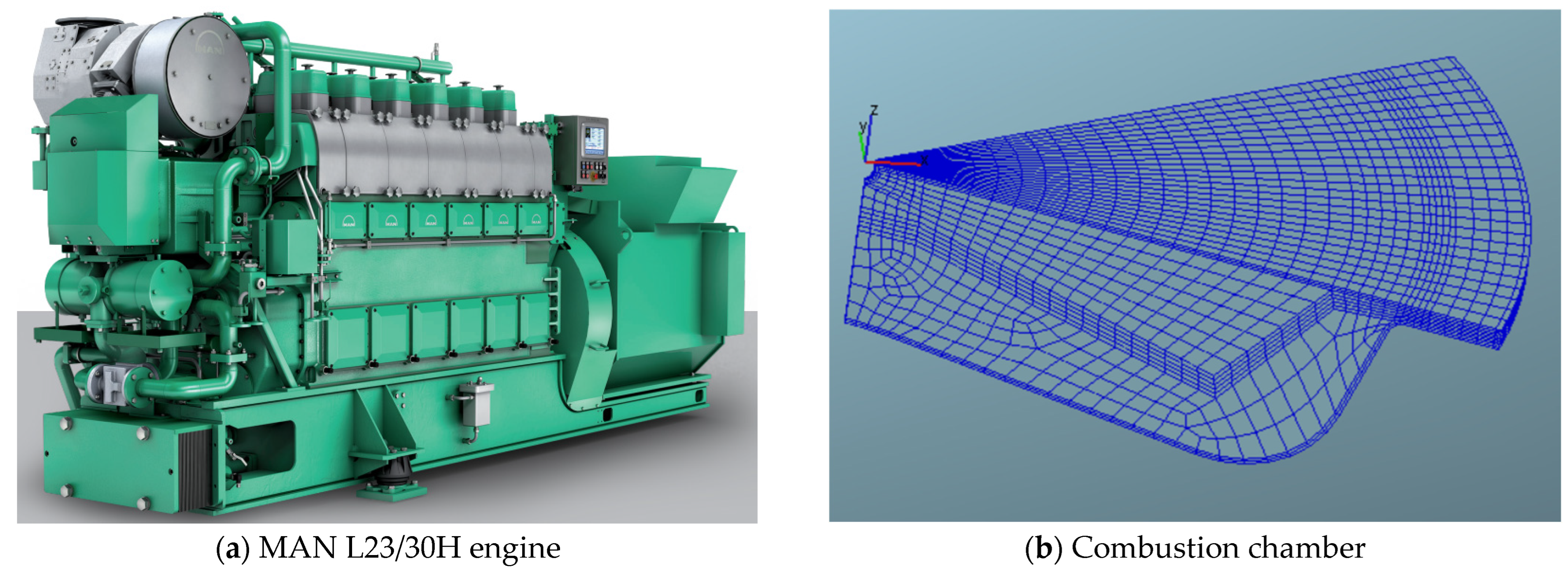
2.2. Simulation Model

The experimental investigations employed a MAN L23/30H four-stroke compression-ignition powerplant (manufactured by ZC Diesel, Zibo, China), characterized as a marine propulsion system with enhanced cylinder dimensions. Key technical specifications of this L23/30H prime mover are detailed in Table 1. This propulsion system incorporates three critical technological implementations: (1) a common-rail direct injection architecture, (2) an electro-hydraulic fuel delivery mechanism, and (3) a robust fuel management configuration. The turbocharging subsystem features a single-stage ABB A165-L turbocharger (made in ABB, Swiss, Baden, Switzerland), complemented by a KLQ50H intercooler unit (manufactured by ZC Diesel, Zibo, China) utilizing single-stage aqueous cooling technology. The appearance and modeling of the engine are shown in Figure 2.
The fuel injection nozzle of the MAN L23/30 marine dual-fuel engine features a configuration of 8 × Φ0.33 mm orifices. A simplified model representing 1/8th of the combustion chamber was employed. Figure 3 presents the final mesh model obtained.

2.3. Simulation Submodel Settings

In the numerical calculations, the influences of the intake and exhaust valves are not considered. The numerical simulation starts at the moment when the intake valve closes and ends at the moment when the exhaust valve opens. At the moment of intake valve closure, the top dead center (TDC) corresponds to 720 °CA, with the intake valve closing 158 °CA before TDC and the exhaust valve opening 128 °CA after TDC. The temperature of the mixed gas inside the cylinder is 328 K, and the fuel composition is a methanol mixture with an equivalence ratio of 1.0. The pressure inside the cylinder is 1.8 bar. The cyclic fuel supply to one cylinder is as follows:
m = b e × p e × τ 120 × n × i g / c y c
In the equation, “ m ” represents the fuel supply per cycle, “ b e ” denotes the fuel consumption rate, “ p e ” stands for the rated power, “ τ ” indicates the number of strokes, “ n ” represents the rotational speed generated by the engine, and “ i ” denotes the number of cylinders. By substituting the initial parameters of the engine into the formula, the calculation yields the following results: the fuel supply per cylinder per cycle is 1.25 g, and the amount of fuel consumed within the calculation domain per cycle is 0.156 g.
Redefine the in-cylinder turbulence parameters according to the engine parameters and estimate the turbulence kinetic energy from
k i n i t = 3 2 v 2
Specify the turbulence length scale as
l i n i t = 0.025 b o r e
Calculate the turbulence dissipation rate from
ε i n i t = C μ 3 / 4 k i n i t 3 / 2 l i n i t
The turbulence characteristics at the intake valve opening phase were determined according to the engine’s geometric specifications. Numerical analysis of in-cylinder turbulence was performed through the Reynolds-Averaged Navier-Stokes formulation coupled with the RNG k-ε turbulent flow closure scheme [13]. Droplet disintegration processes were simulated using the KH-RT hybrid model, with critical coefficients adapted from the spray atomization parameters established in Shi’s experimental study [14], as detailed numerically in Table 2. Vaporization dynamics were governed by the Frossling correlation, while inter-droplet interactions followed the NTC collision algorithm. The detailed chemistry-based SAGE framework was implemented to simulate combustion processes, enabling flexible selection of chemical kinetic mechanisms and thermodynamic databases according to computational objectives. This combustion solver remained active throughout the complete injection-combustion sequence. All supplementary computational modules employed in this investigation are systematically cataloged in Table 2.

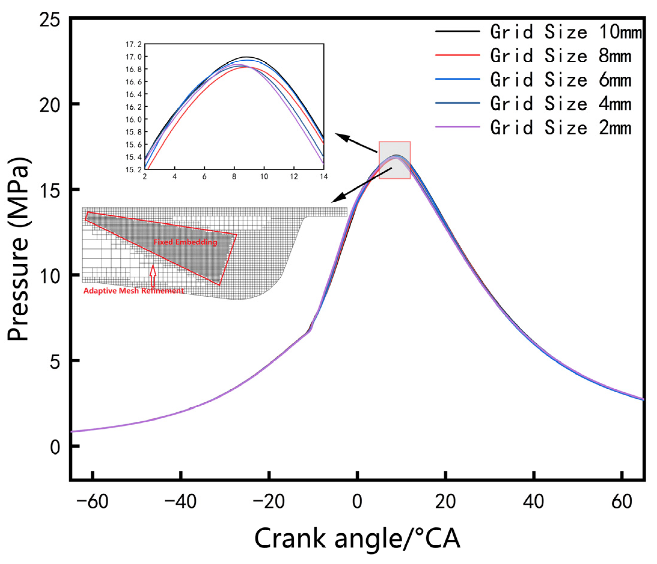
2.4. Simulation Model Calibration

The computational framework validation and engine model calibration process referenced empirical data from conventional diesel operations using an identical hardware configuration [23]. Numerical investigations evaluated four primary grid resolutions (8 mm, 6 mm, 4 mm, and 2 mm). Implementing the 4 mm reference configuration, boundary layer treatment employed dual-level dynamic adaptation while fuel atomization zones utilized triple-layer localized enhancement [24]. Figure 4 illustrates the optimized spray pattern and wall-adjacent mesh configurations proximate to the maximum compression position.
Computational input data originated from Zhenjiang CSSC Marine Power Co., Ltd. (Zhenjiang, China). Experimental measurements of cylinder pressure profiles from engine performance testing were employed to verify the numerical model’s accuracy [25]. As illustrated in Figure 5, when operating at standard parameters (operational speed: 900 rpm; fuel delivery quantity: 1.25 g; injection phase: −5° crank angle), the computational predictions demonstrated strong alignment with empirical observations, exhibiting negligible deviation and consistent reproduction of pressure curve transitional features [26]. This confirms the validity of the reconstructed combustion system geometry, developed from precise engine dimensional specifications and optimized meshing configurations, for subsequent numerical investigations. To maintain equilibrium between computational fidelity and resource constraints, all simulation scenarios adopted a fundamental 4 mm spatial resolution across varied operational modes [27].

3. Results and Discussion

The ignition characteristics of methanol engines have a significant impact on engine performance, with the quality of ignition assessed by the engine’s ability to achieve stable ignition and heat release rate. In order to comprehensively match the optimal ignition energy, ignition position, and other relevant parameters for this engine, this paper conducts simulation calculations under varying ignition energies, depths of ignition position, and ignition position offsets. The analysis focuses on the influence of these parameters on in-cylinder temperature, pressure, combustion heat release rate, and emission performance, aiming to identify the optimal ignition characteristic parameters to fully unleash the best performance of the methanol engine.

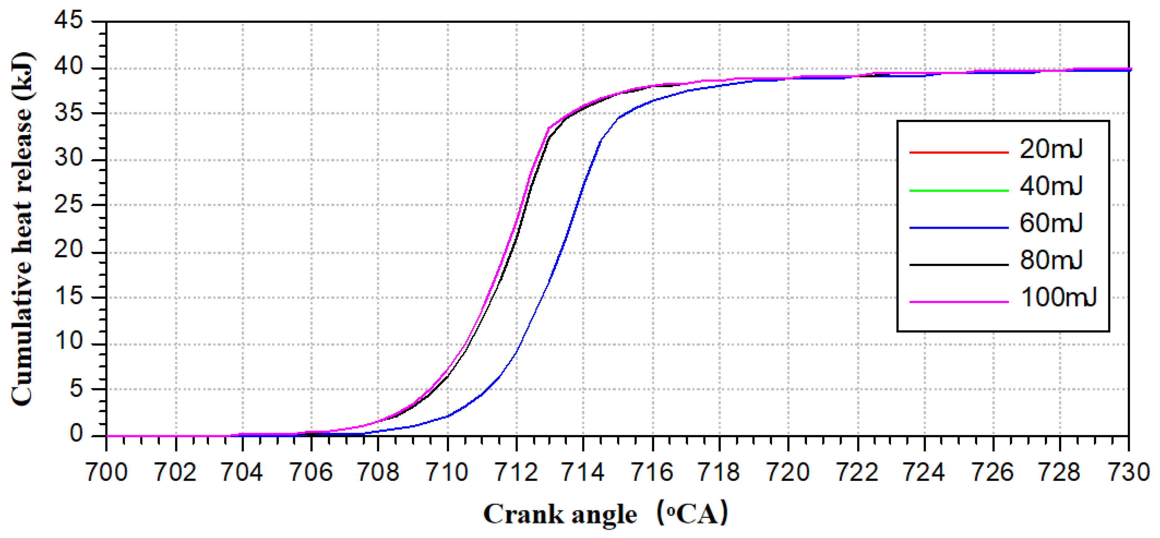
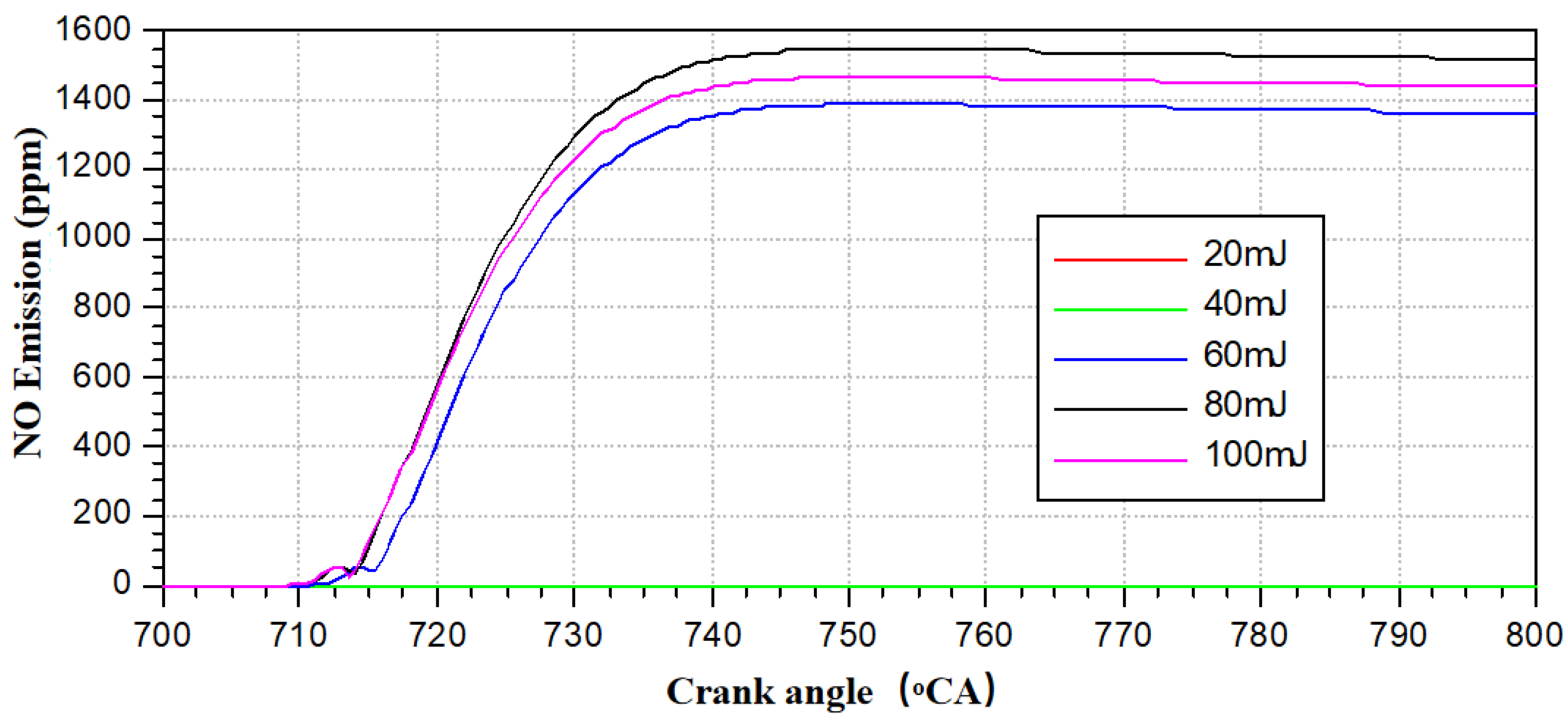
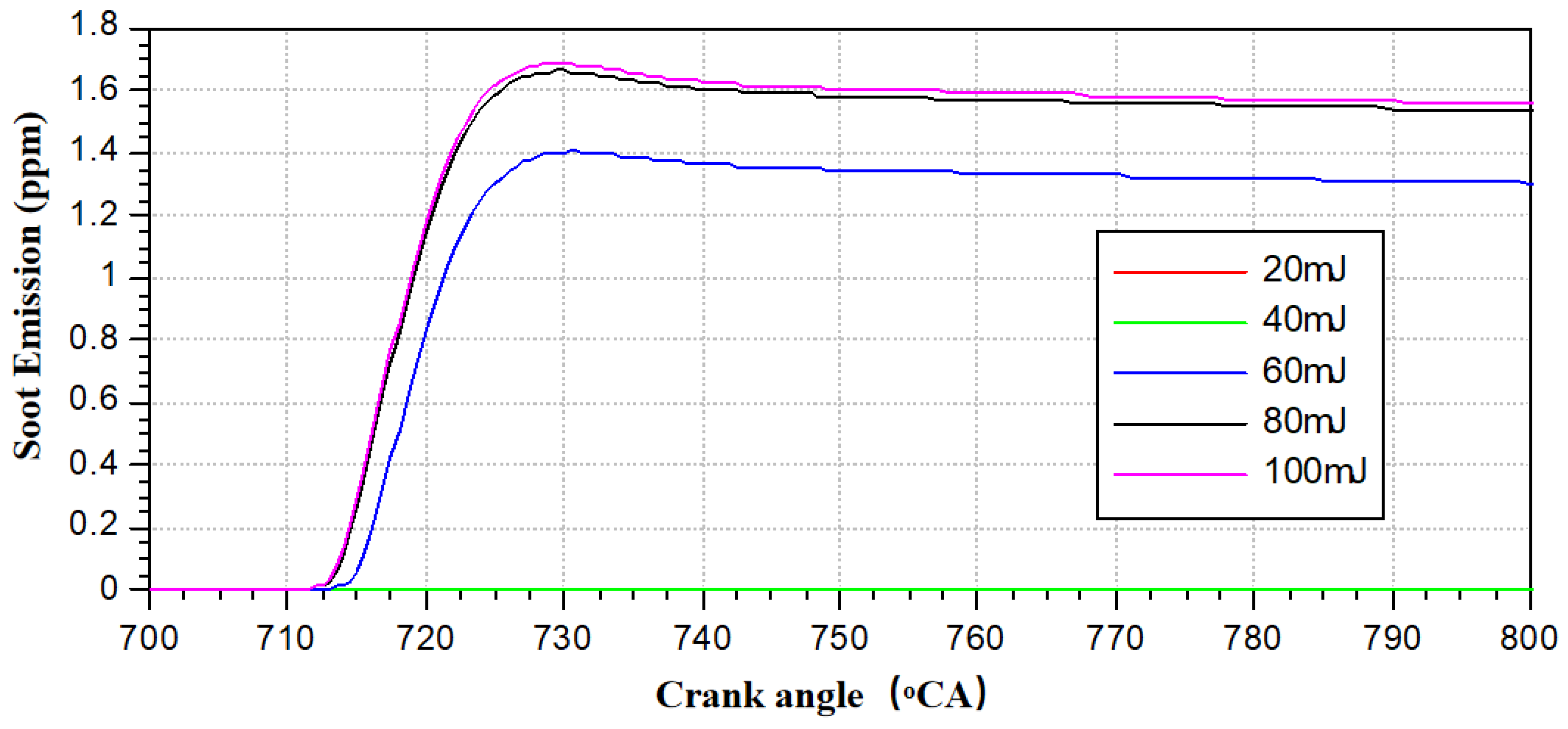
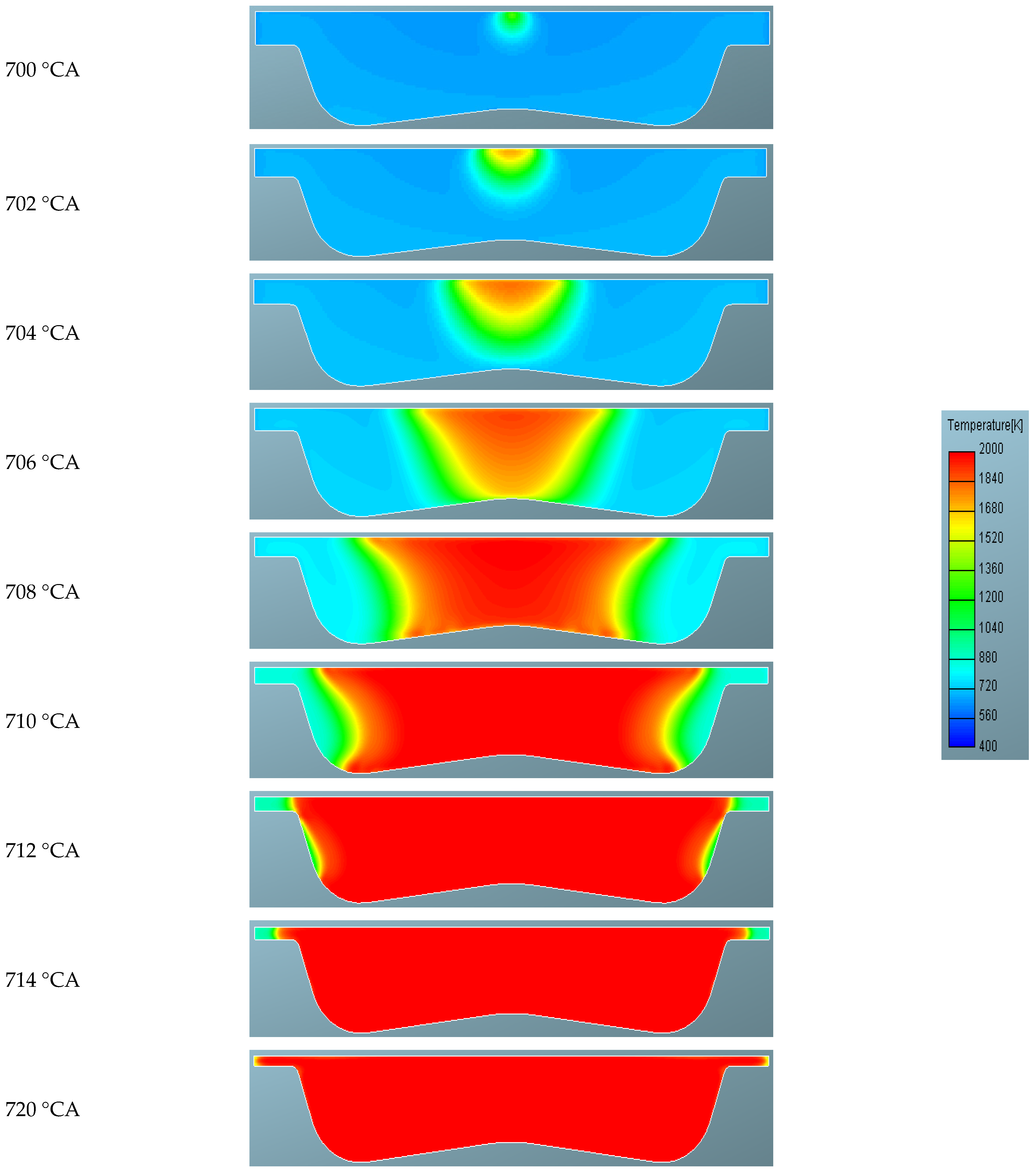
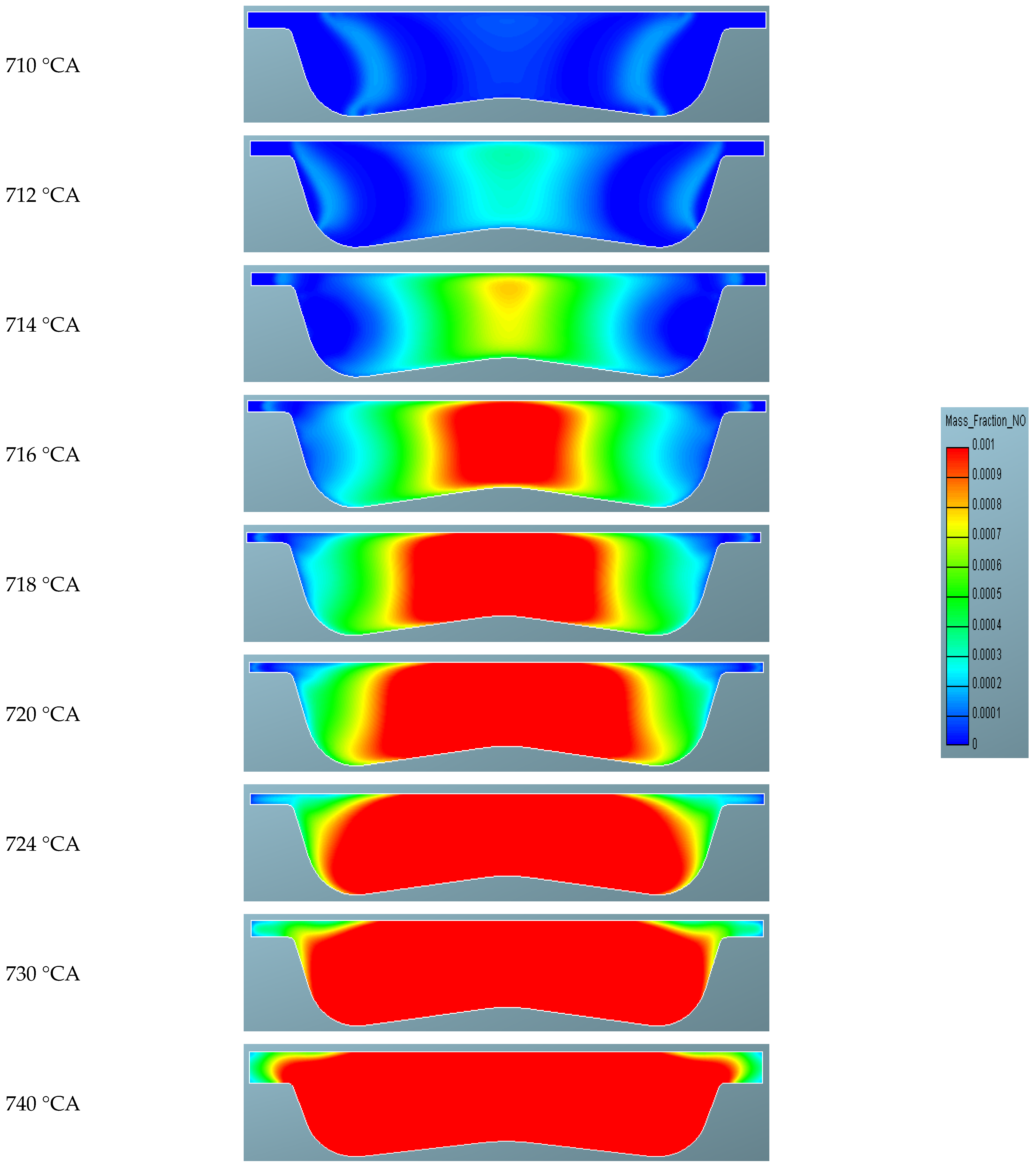
3.1. Influence of Laser Ignition Energy on the Performance of Methanol Engines

The magnitude of ignition energy is crucial to the performance of methanol engines. Insufficient ignition energy can lead to ignition failure, unstable operation, and poor consistency, while excessive ignition energy results in wasted energy and redundant ignition system structures. Ignition energy is one of the most critical factors determining the normal operation of methanol engines. Simulation methods can quickly and efficiently screen out relatively appropriate ignition energies. Therefore, conducting simulation studies on the impact of different ignition energies on engine performance is highly necessary. The laser ignition energy meter is shown in Table 3.
The ignition energy was tested in increments of 20 mJ until successful ignition and stable combustion were achieved. The ignition energy was positioned at the center of the cylinder and 5~6 mm below the bottom plane of the cylinder head.
Figure 6a,b show the relationship between in-cylinder pressure and temperature with crank angle under different ignition energies. It can be observed that when the ignition energy is less than 60 mJ, the pressure and temperature in the cylinder are significantly lower. Compared to the symmetric state at top dead center, it can be inferred that the methanol in the cylinder did not ignite, and the cylinder was in a pure compression state. The reason for failure to ignite when ignition energy is below 60 mJ lies in the requirement to overcome activation energy and heat loss during methanol-air mixture ignition. When the ignition energy is between 60 and 80 mJ, the methanol mixture can be ignited smoothly, but the ignition delay period is relatively longer compared to 80 mJ and 100 mJ, and ignition may be unstable. When the ignition energy is greater than 80 mJ, the in-cylinder pressure and temperature curves are basically consistent with the results at 100 mJ ignition energy. It can be concluded that when the ignition energy is greater than 80 mJ, the methanol mixture can be ignited smoothly, and the combustion state in the cylinder remains basically stable as the energy continues to increase.
Figure 7 and Figure 8 present the relationship between in-cylinder combustion heat release rate, cumulative heat release, and crank angle under different ignition energies. It can be observed that when the ignition energy is below 60 mJ, there is no combustion heat release phenomenon in the cylinder, further indicating that the methanol in the cylinder has not been successfully ignited at energies below 60 mJ. When the ignition energy exceeds 60 mJ, the methanol mixture is successfully ignited, but the ignition delay period is significantly longer than that at 80 mJ and 100 mJ ignition energies, and the combustion is not in a stable state. When the ignition energy is greater than 80 mJ, the curves of in-cylinder combustion heat release rate and cumulative heat release basically coincide, indicating that the combustion state tends to be consistent. When the ignition energy exceeds 80 mJ, the laser energy becomes sufficient to form a large-sized, high-temperature flame kernel within an extremely short time, and its stability is no longer significantly affected by the ignition energy. At this stage, flame propagation is primarily governed by in-cylinder turbulence and mixture state, while the marginal benefits of further energy enhancement diminish.
Figure 9 presents the relationship between in-cylinder NO emissions and crank angle under different ignition energies. It can be observed that after successful ignition, the NO emissions of the methanol engine rapidly increase, reaching a peak at around 740 °CA and stabilizing at a peak level of approximately 1500 ppm. This NO emission level is relatively high, primarily due to the fact that methanol fuel is oxygen-rich, providing O atoms during the combustion process, which is one of the necessary conditions for the formation of nitrogen oxides.
Figure 10 shows the relationship between in-cylinder Soot emissions and crank angle under different ignition energies. It can be seen that the stable Soot emission level is below 2 ppm, which is extremely low. This is likely because methanol is a small-molecule chemical fuel, containing only one C atom within its molecule and lacking long-chain carbon structures. Therefore, its Soot emission level remains at a low level.
Figure 11 presents the temperature contour distribution within the cylinder at an ignition energy of 80 mJ. It can be observed that after the laser delivers the ignition energy at 695 °CA, a noticeable flame kernel forms near the ignition laser location within the cylinder at 700 °CA, with an ignition delay period of approximately 5 °CA. Following the formation of the flame kernel, the high-temperature flame rapidly spreads inwards within the combustion chamber and gradually fills the entire space. Since the ignition laser is located at the center of the cylinder and the airflow within the cylinder is symmetrical around the center, the flame propagation exhibits a symmetrical distribution around the cylinder center during the process.
Figure 12 presents the contour distribution of methanol mass fraction within the cylinder at an ignition energy of 80 mJ. As the ignition flame develops, the methanol mass within the cylinder rapidly decreases and spreads outward from the ignition point along with the flame propagation. The distribution of methanol mass fraction is generally consistent with that of the temperature contour within the cylinder, indicating that the methanol in the flame zone rapidly burns and generates a large amount of heat. The 80 mJ ignition energy provides sufficient initial flame kernel energy to enable the system to cross the critical state, ultimately achieving efficient and synchronous fuel consumption and heat release. By 714 °CA, the methanol within the cylinder is basically consumed by combustion.
Figure 13 presents the contour distribution of NO emission mass fraction within the cylinder at an ignition energy of 80 mJ. Since the formation of NO emissions requires both high temperature and oxygen-rich conditions, it can be observed from the contour that the initial generation of NO does not occur near the ignition kernel, but rather on the high-temperature flame propagation surface. As combustion progresses, the temperature within the cylinder gradually increases, and NO emissions rapidly form and accumulate at the center of the cylinder.

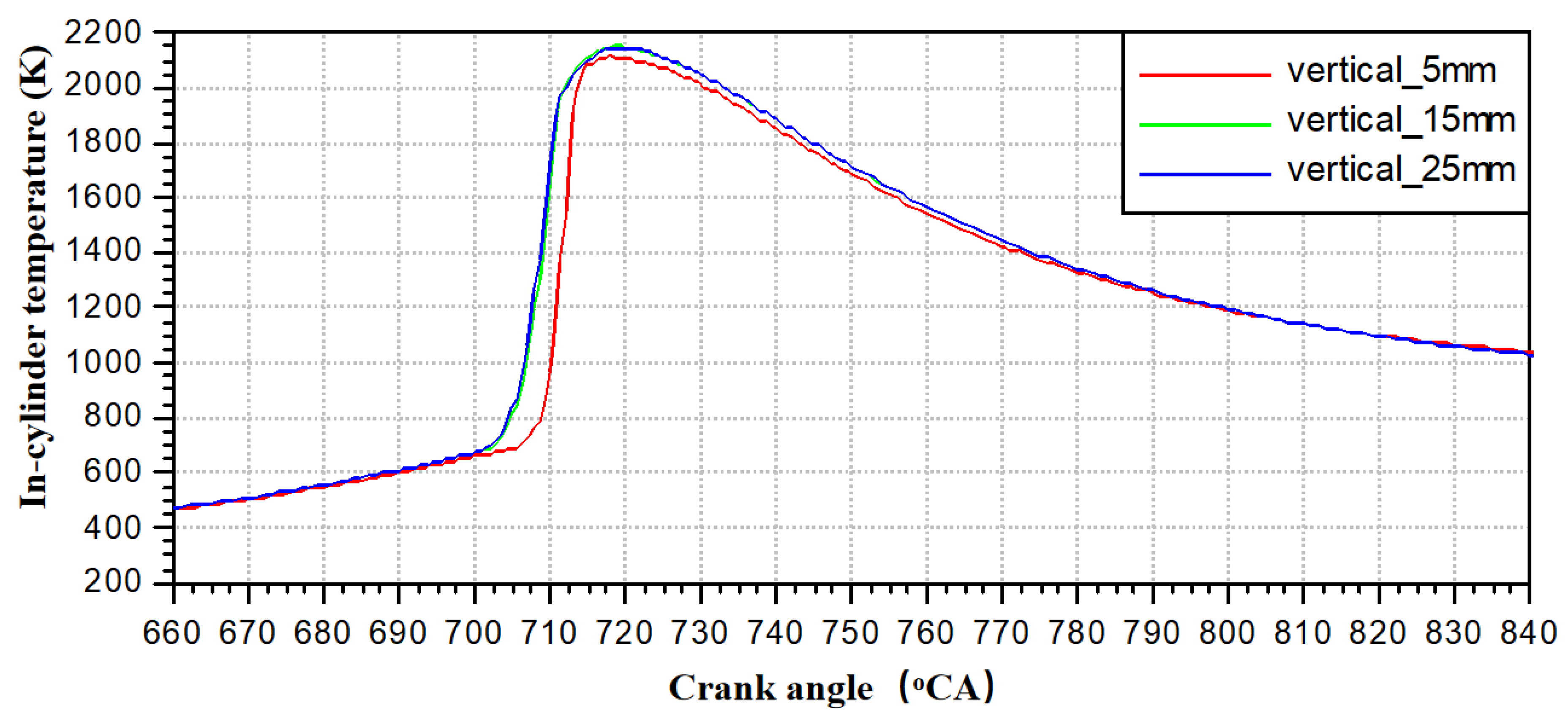
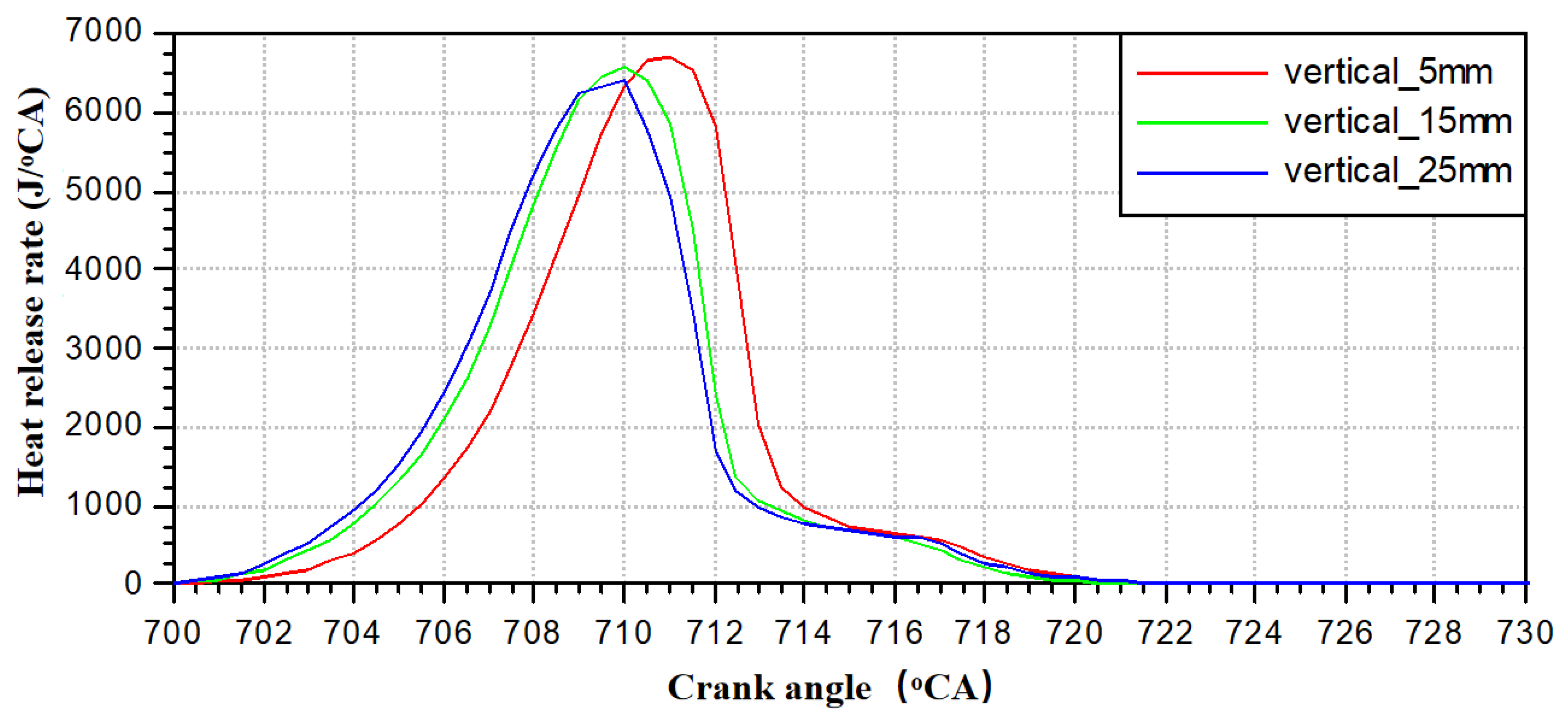
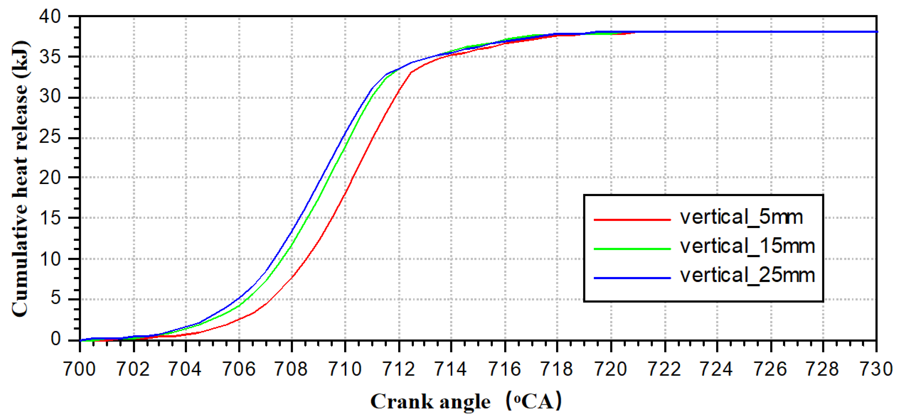
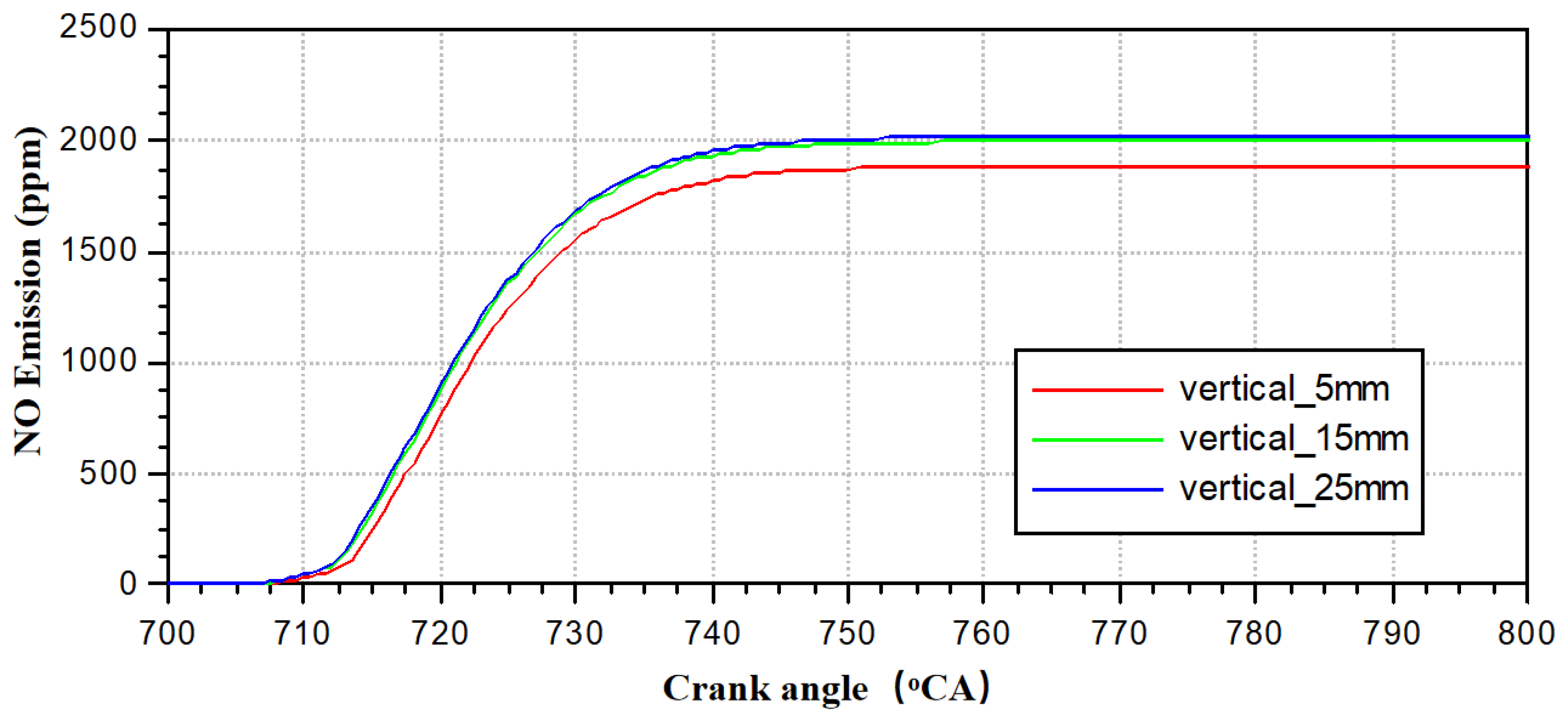
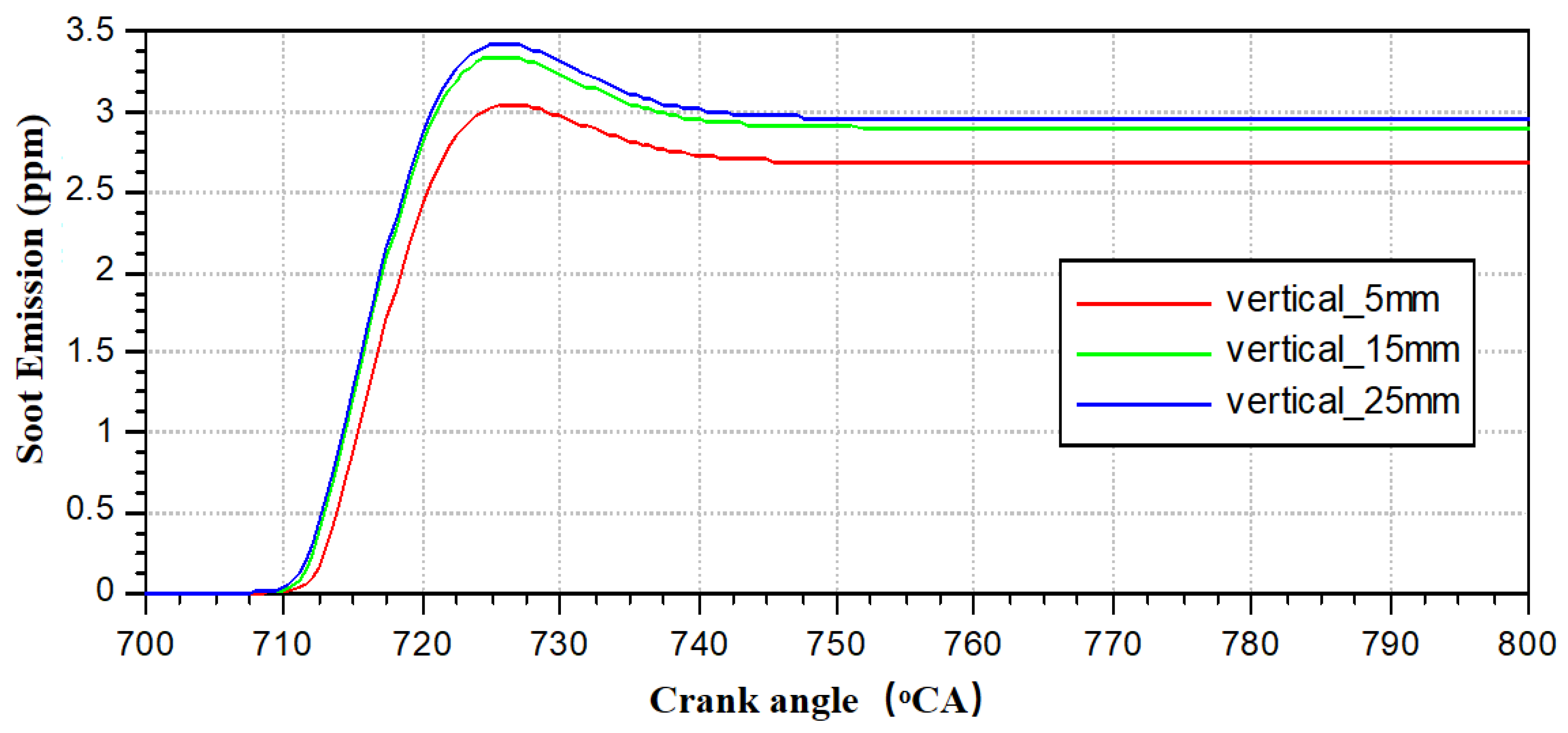
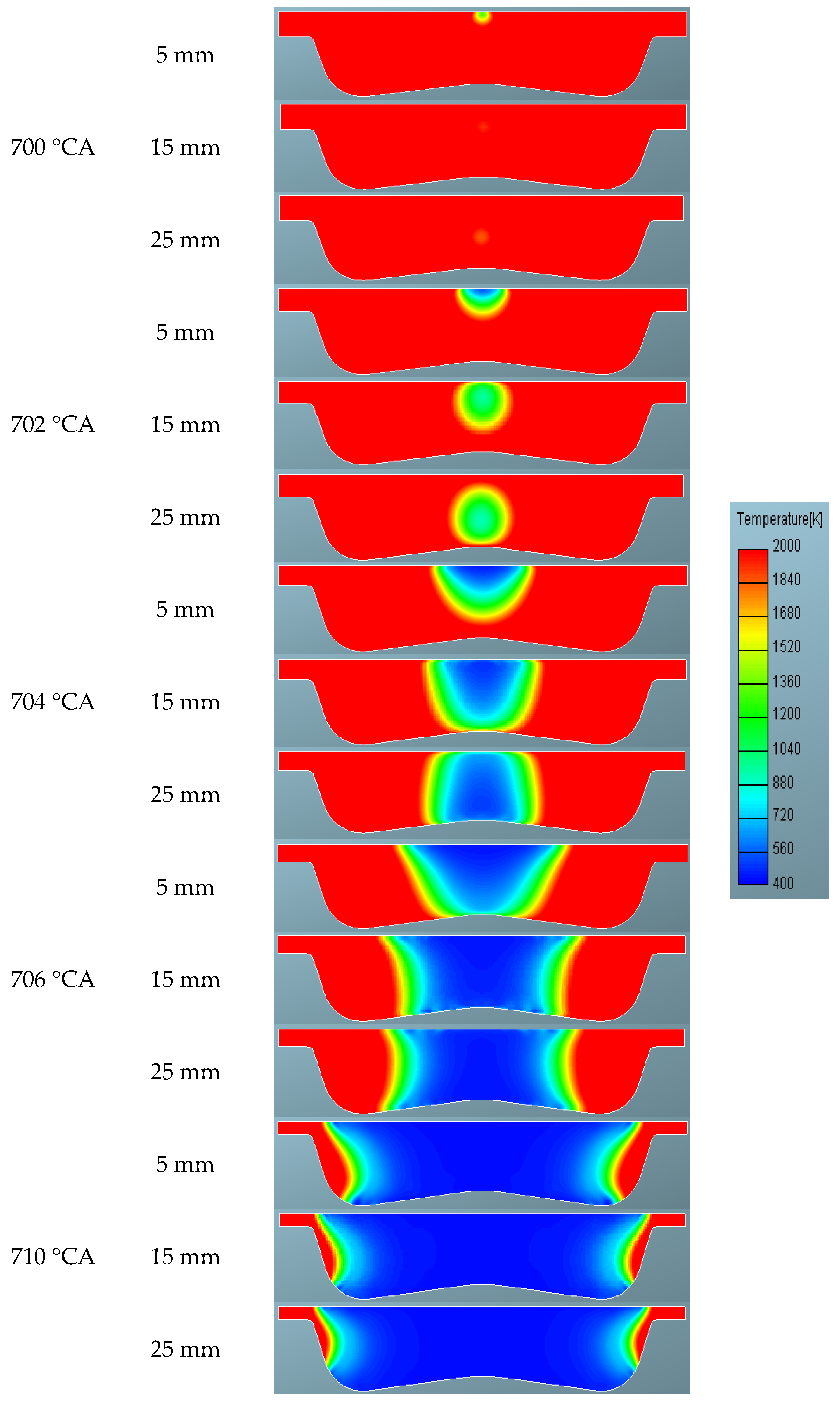
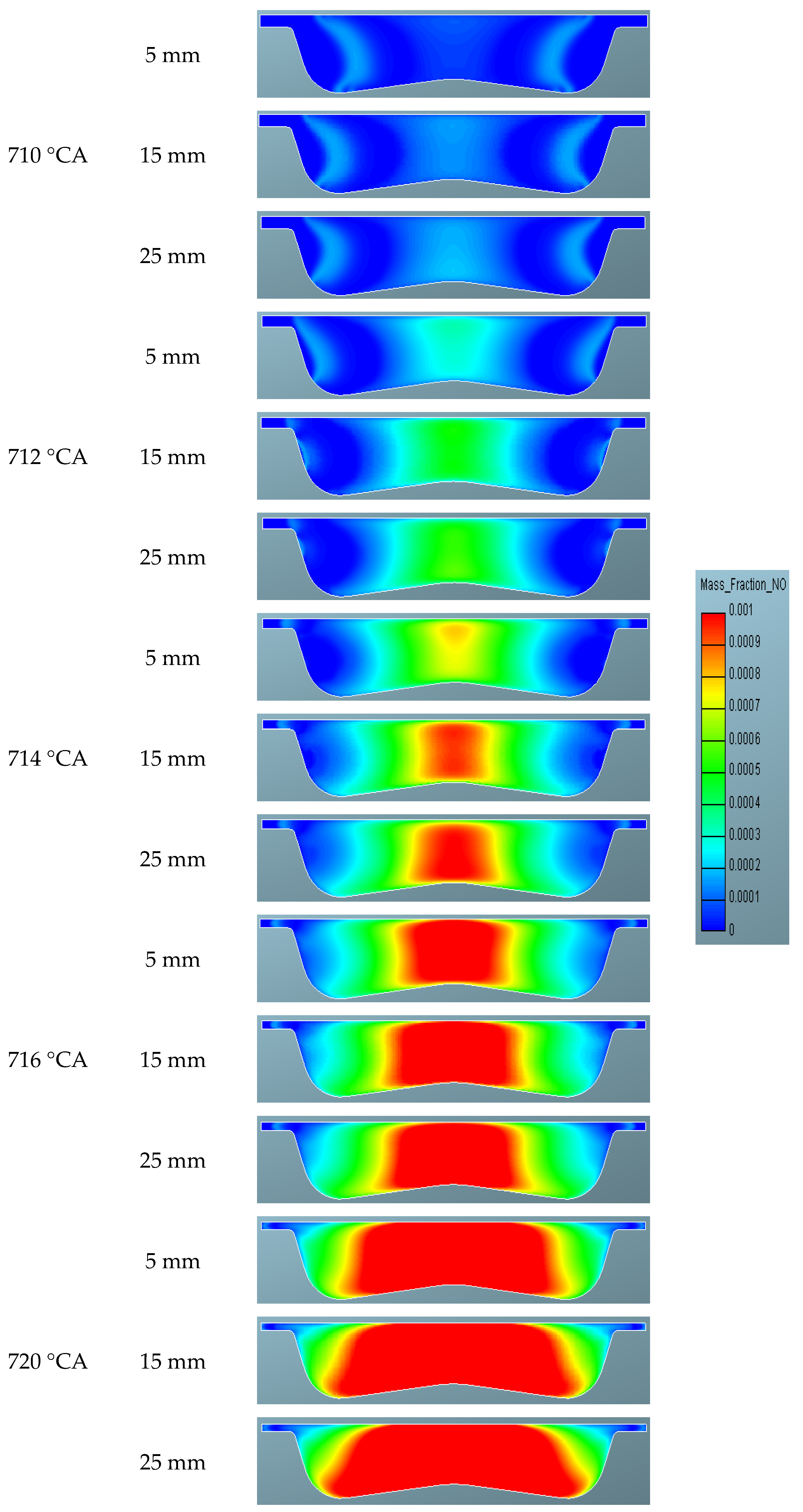
3.2. Influence of Laser Ignition Longitudinal Position on the Performance of a Methanol Engine

The longitudinal position depth of laser ignition has a crucial impact on the structural arrangement of the laser generator, the design of the valve motion profile, and the design of the piston clearance height. A reasonable placement of the longitudinal position of the laser ignition kernel is beneficial for improving the ignition success rate and reducing the likelihood of engine misfires. Additionally, this parameter is one of the important input conditions for the design of valves and pistons. The vertical position table of laser ignition is shown in Table 4.
Simulation studies were conducted with the laser ignition position varying in 10 mm increments along the cylinder centerline until the ignition position exceeded the combustion chamber boundary. Three sets of comparative simulation studies were carried out at 5 mm, 15 mm, and 25 mm, respectively.
Figure 14 and Figure 15 present the relationship between in-cylinder pressure and temperature with crank angle at different laser longitudinal ignition depths. It can be observed that when the laser longitudinal ignition depth is adjusted from 5 mm to 15 mm, the onset of the rapid rise in both in-cylinder pressure and temperature occurs significantly earlier. However, when the depth is further increased to 25 mm, the onset of the rapid rise remains essentially unchanged. Methanol-air mixture exhibits concentration stratification within the cylinder. The 15 mm depth likely corresponds to fuel vapor-enriched regions, while the 5 mm depth may reside in lean zones requiring prolonged time to accumulate active radicals for combustion initiation. Additionally, the 5 mm ignition depth near the combustion chamber wall causes laser energy to be easily absorbed by low-temperature wall heat dissipation (wall quenching), resulting in reduced initial temperature of the flame kernel. Therefore, a certain longitudinal depth of the laser ignition position helps to shorten the ignition delay period and accelerate the rapid formation of the ignition kernel. As the longitudinal depth increases, both the maximum pressure and temperature peaks within the cylinder exhibit a certain degree of increase, indicating that with the increase in laser ignition longitudinal depth, the intensity of combustion within the cylinder is further enhanced.
Figure 16 and Figure 17 present the relationship between the in-cylinder combustion heat release rate and the cumulative heat release with crank angle at different laser longitudinal ignition depths. It can be observed that as the laser longitudinal depth increases, the onset of both the instantaneous heat release rate and the cumulative heat release occurs significantly earlier. The peak of the instantaneous heat release rate decreases to some extent, while the peak of the cumulative heat release remains relatively consistent in position. The decrease in peak instantaneous heat release rate occurs because deep ignition corresponds to high-turbulence zones where flame front wrinkling intensifies, but excessive turbulence can cause localized flame quenching (extinction) or combustion fragmentation, leading to an overall smoothing of the heat release rate profile, reduced peak values, and extended combustion duration.
Figure 18 and Figure 19 present the relationship between in-cylinder NO and Soot emissions with crank angle at different laser longitudinal ignition depths. It can be observed that as the laser ignition longitudinal depth increases, both NO and Soot emissions exhibit a certain degree of deterioration. However, the NO emission values are relatively high, with an increase of approximately 20%. Compared to NO emissions, the absolute values of Soot emissions are smaller, so the increase in this case can be basically ignored. The increase in NO emissions with deeper ignition depth is attributed to advanced combustion initiation timing caused by deep ignition, which results in more heat release being completed as the piston approaches top dead center (TDC), significantly elevating in-cylinder peak temperature and prolonging high-temperature duration. According to the Zeldovich mechanism, the NO generation rate exhibits an exponential relationship with temperature—every 100 K temperature rise increases the NO formation rate by 3–5 times.
Figure 20 presents a comparison of in-cylinder temperature contours at different laser longitudinal ignition depths. It can be observed that as the laser ignition longitudinal depth increases, the position where the ignition kernel forms gradually lowers, indicating that the formation of the ignition kernel is directly related to the longitudinal depth of the laser ignition. After the kernel forms, the flame begins to propagate rapidly within the cylinder. The flame propagation speed at 15 mm and 25 mm ignition depths is significantly faster than that at 5 mm, and the area of the high-temperature region formed at the center of the cylinder is also larger. In the later stages of combustion, the flame propagation speed at 25 mm is noticeably slower than that at 15 mm and 5 mm, with significant areas around the combustion chamber remaining unfilled by high-temperature combustion gases in the 25 mm case. Overall, the distribution of the high-temperature region is optimal for the 15 mm case, followed by the 25 mm case, with the 5 mm case being the least optimal. During the late compression stroke, the in-cylinder tumble flow breaks up and forms a high turbulent kinetic energy zone (with peak turbulence intensity located in the lower-central region). The 15–25 mm ignition depth precisely resides within this zone, where the flame kernel during its initial growth phase is subjected to strong turbulent disturbances, resulting in increased effective flame surface area and significantly enhanced turbulent flame speed.
Figure 21 presents a comparison of in-cylinder mass fraction contours at different laser longitudinal ignition depths. It can be observed that as the laser ignition longitudinal depth increases, the position where the ignition kernel forms gradually lowers, and a rapid decrease in the mass fraction concentration of methanol occurs. The mechanism behind the downward displacement of flame kernel position with increased ignition depth is attributed to laser energy deposition near the combustion chamber’s upper surface, where spray-wall impingement evaporation cooling creates a fuel-lean mixture environment, forcing the flame kernel to overcome enhanced thermal losses (wall quenching) under diluted conditions, resulting in delayed kernel formation and spatially constrained development. After the kernel forms, the flame begins to propagate rapidly within the cylinder, with the methanol in the flame front undergoing rapid combustion and releasing energy. The concentration of the methanol-air mixture behind the flame front is significantly lower than that in the unburned region ahead of the flame front. When the laser longitudinal depth is 25 mm, the propagation speed of the flame front is the fastest in the early stages of combustion. However, in the later stages, the combustion speed at a depth of 15 mm accelerates, resulting in the lowest concentration of unburned methanol within the cylinder. Laser longitudinal depth significantly influences flame propagation characteristics, showing a 23% increase in flame propagation speed at 15 mm depth and a reduction of unburned methanol mass fraction to 0.8% at the end of combustion. The cause of flame speed reversal during the late combustion stage is attributed to the rapid consumption of the central fuel-rich mixture in the early combustion phase, leaving residual lean mixture in peripheral regions. During the expansion stroke, turbulence intensity decays, leading to an insufficient flame propagation driving force. Simultaneously, laminar flame speed drops sharply in lean mixture, resulting in flame front stagnation.
Figure 22 shows the contour distribution of in-cylinder NO emissions at different laser longitudinal ignition depths. It can be seen that in the early stages of combustion, the regions of NO formation are mainly concentrated in the flame front area, possibly due to the higher combustion temperatures and relatively higher oxygen concentrations in this region. As combustion continues, the high-concentration regions of NO emissions concentrate towards the center of the cylinder, and the concentration increases with the duration of combustion. This phenomenon may be attributed to the irreversible nature of NO formation; as the combustion process progresses, NO gradually accumulates and concentrates in the relatively weak airflow region at the center of the cylinder.

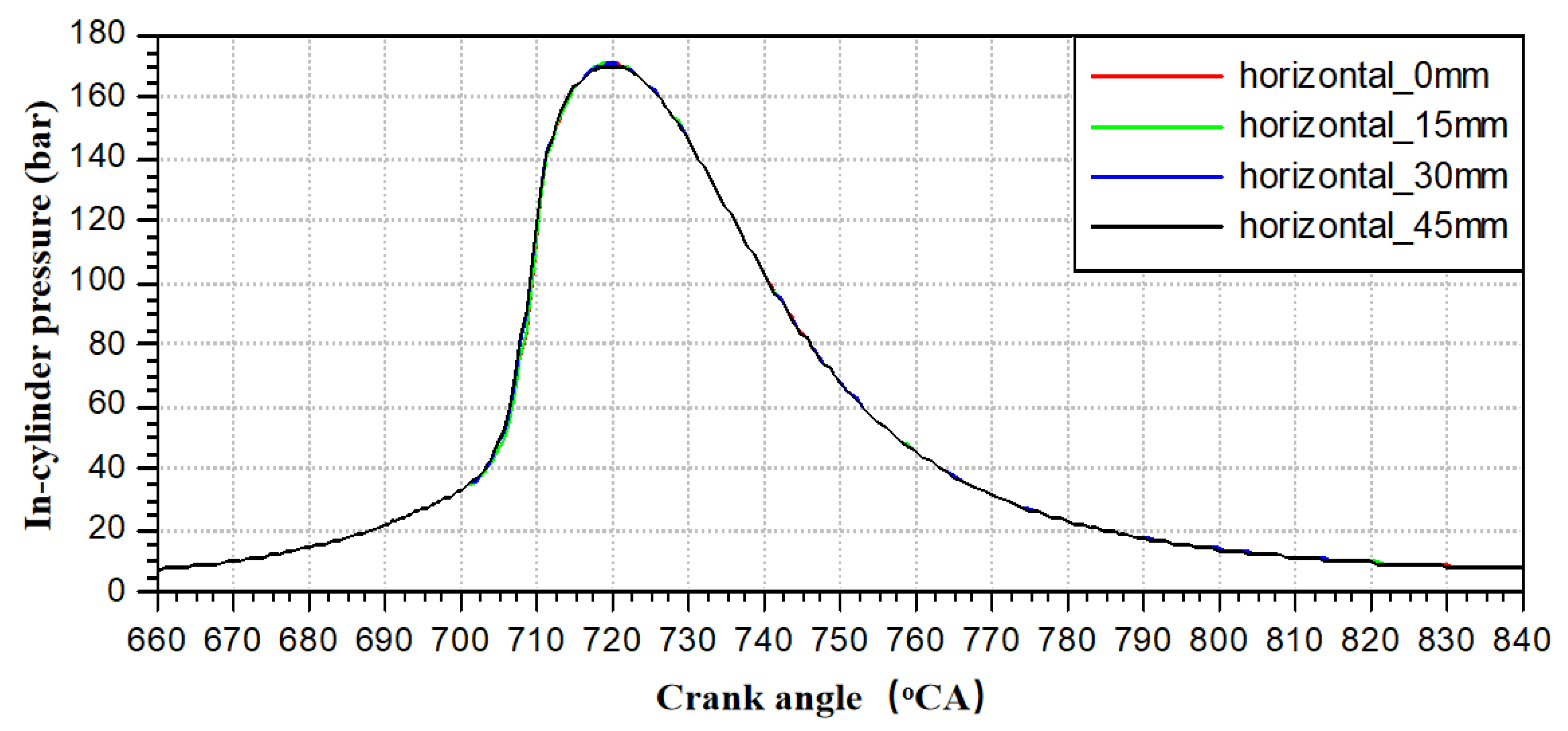
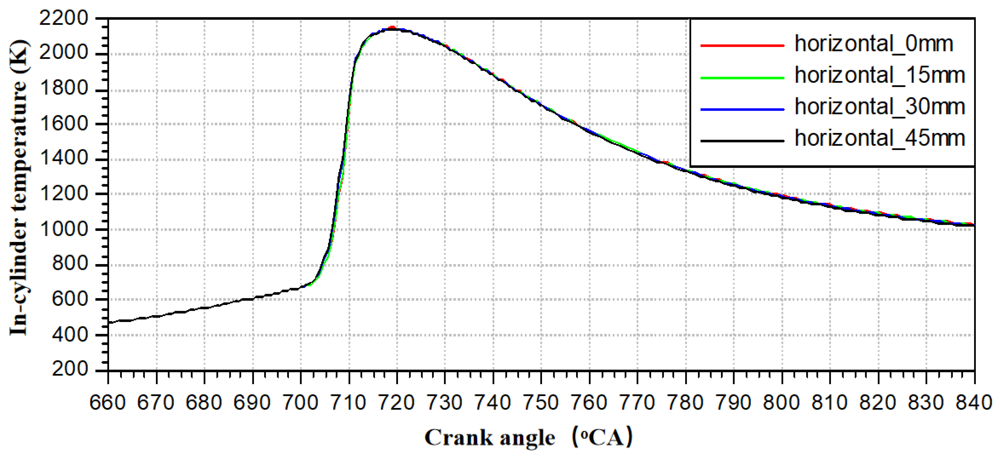
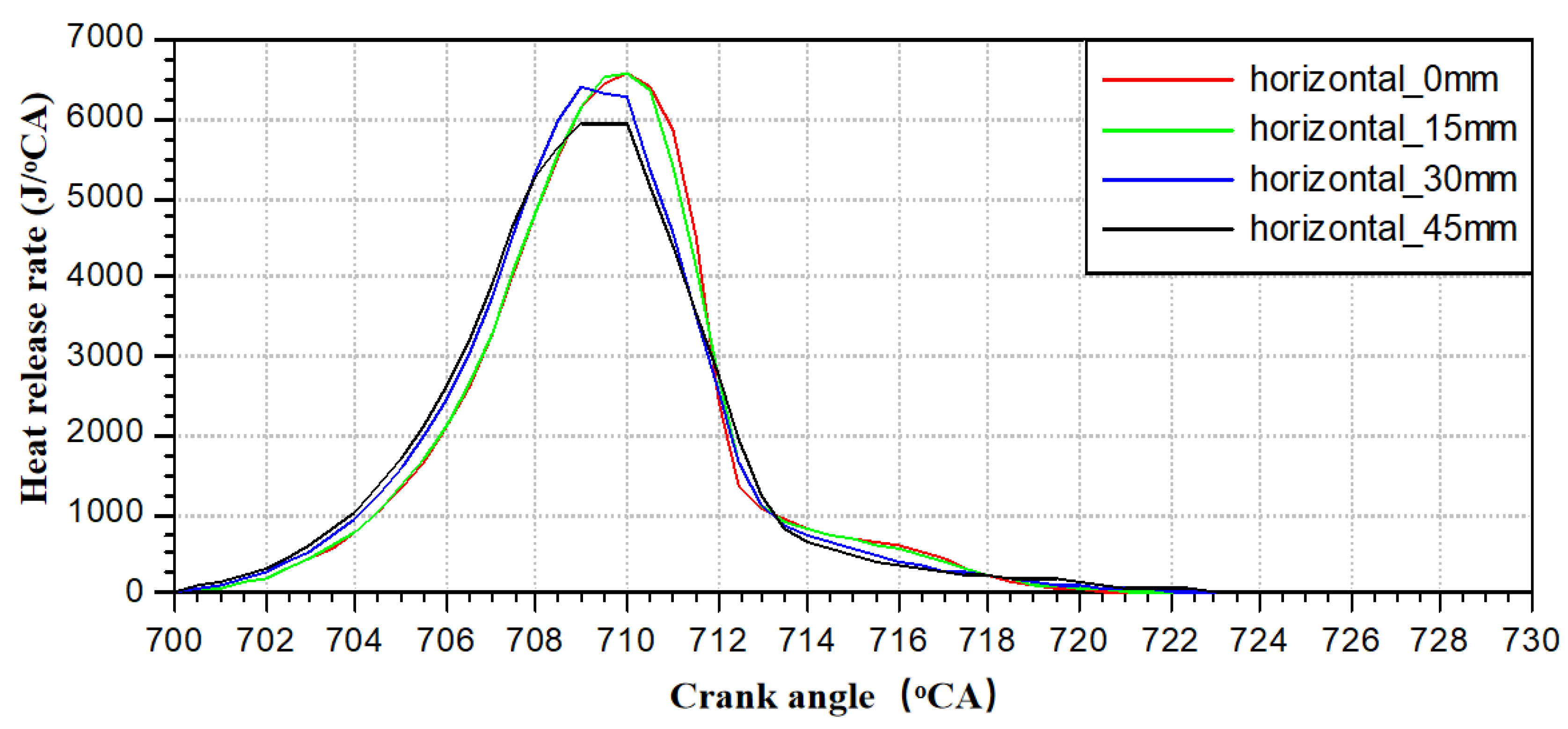
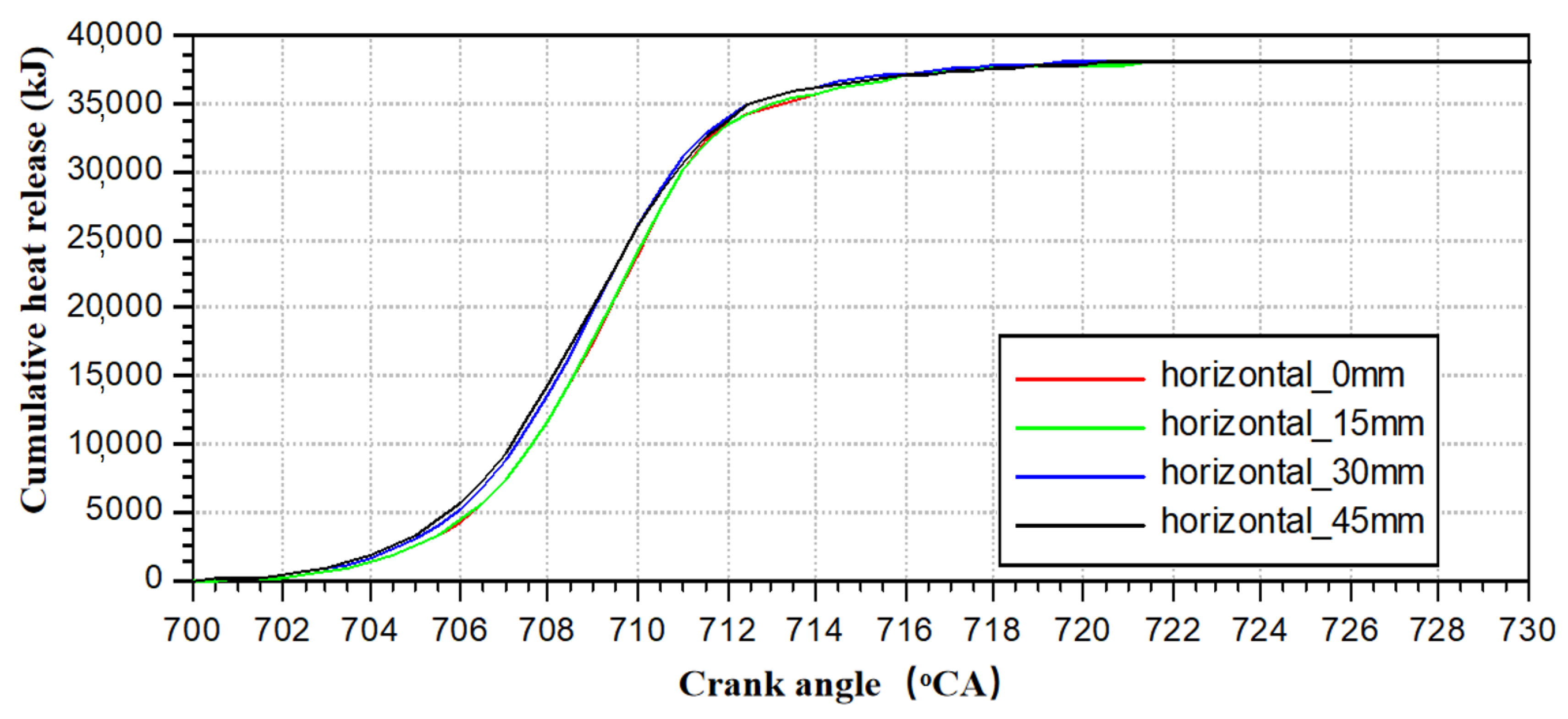
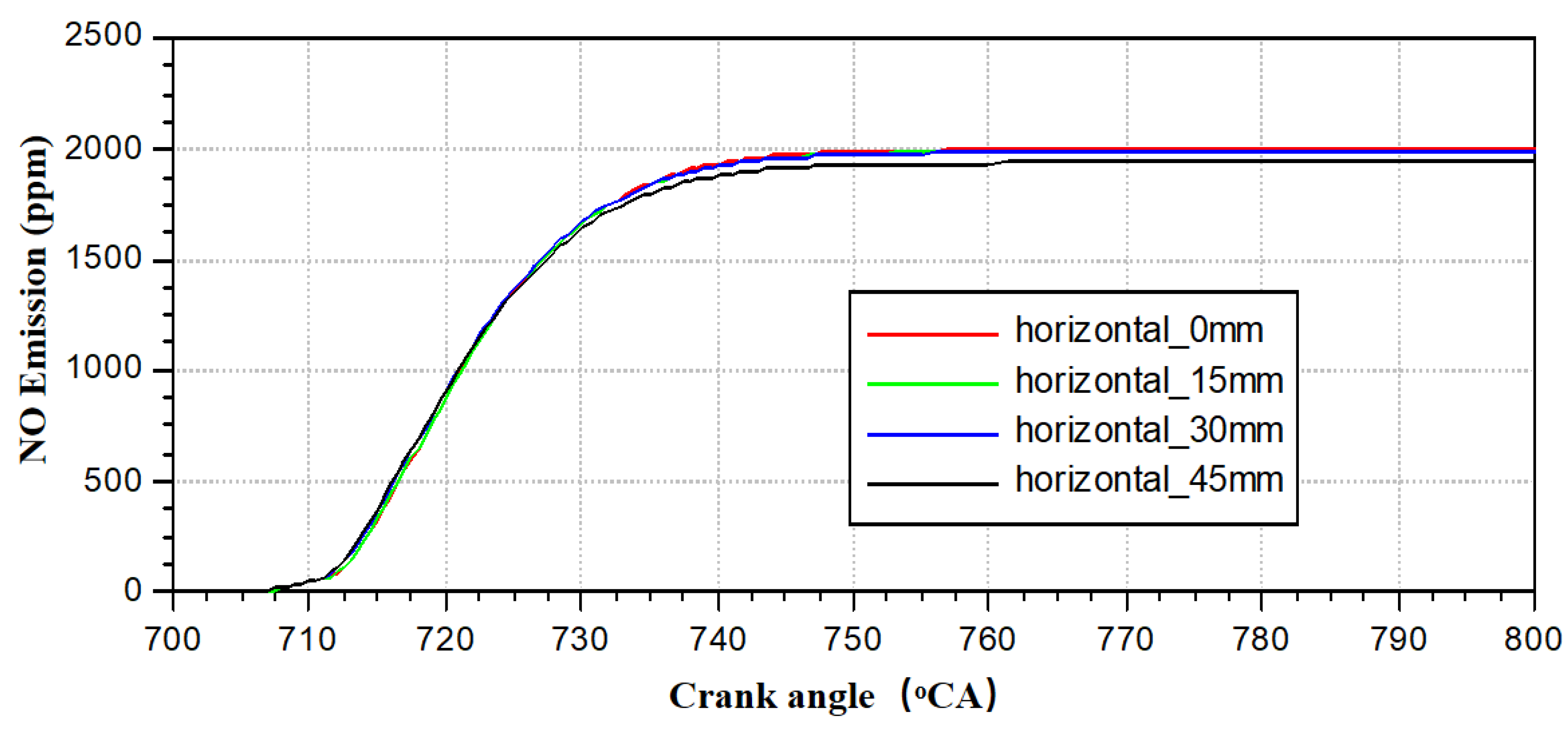
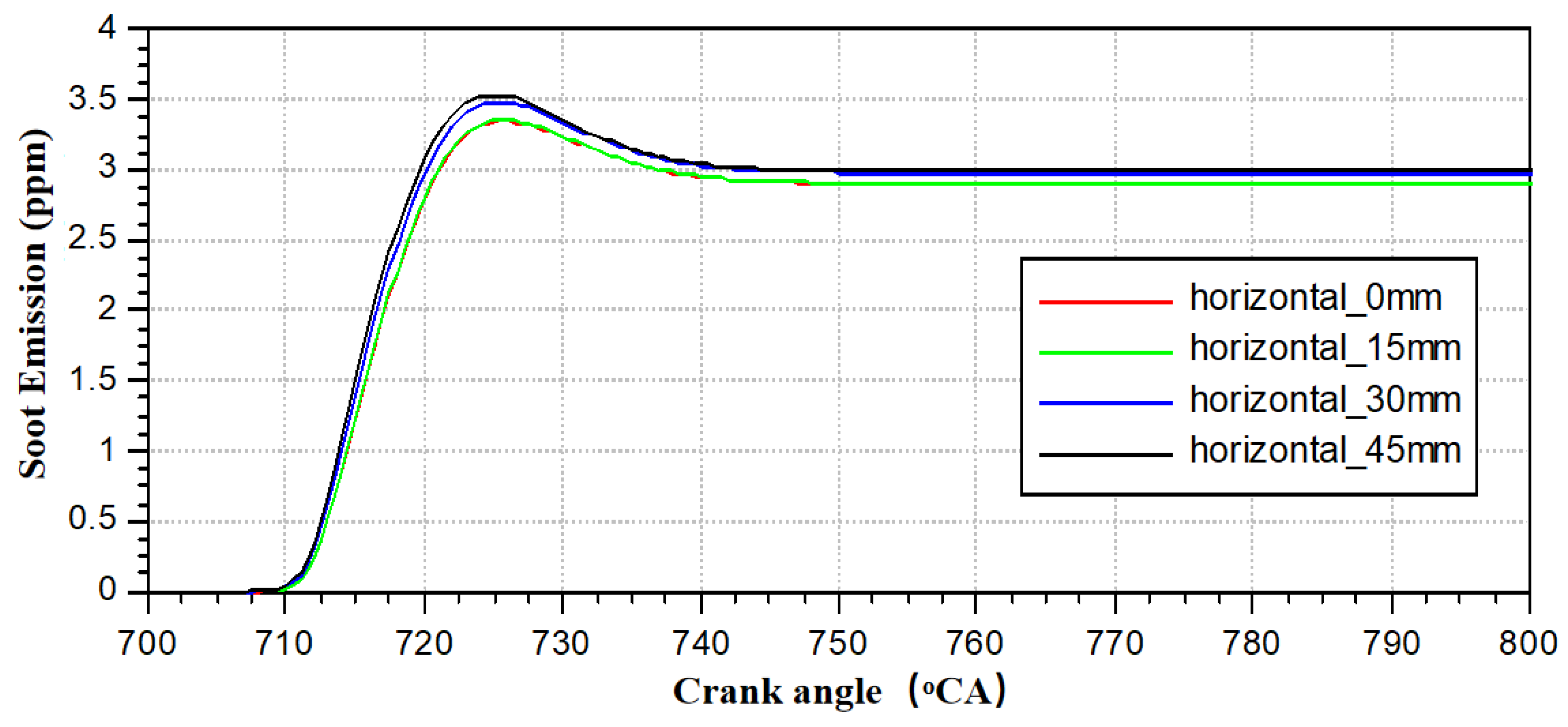
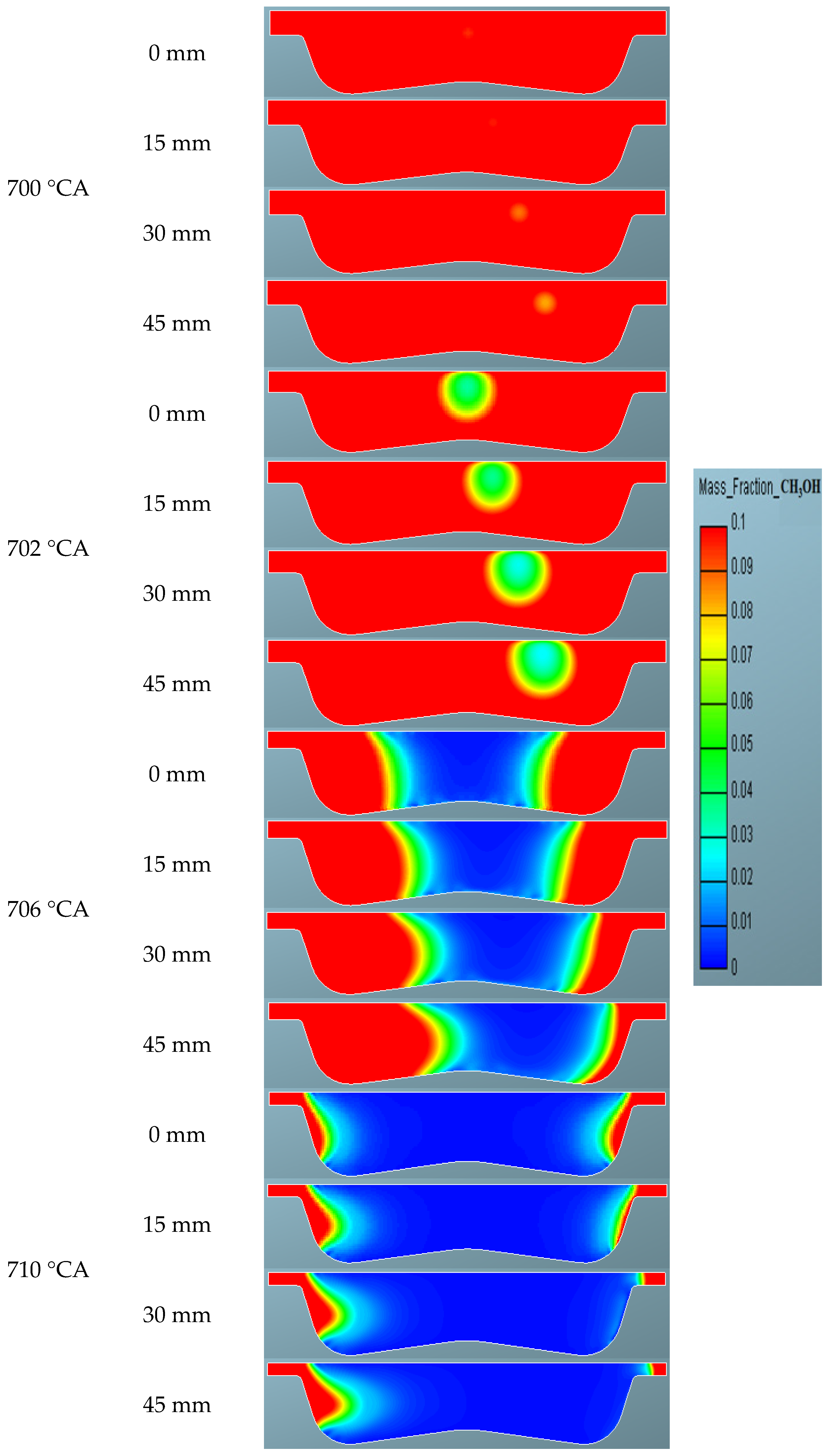
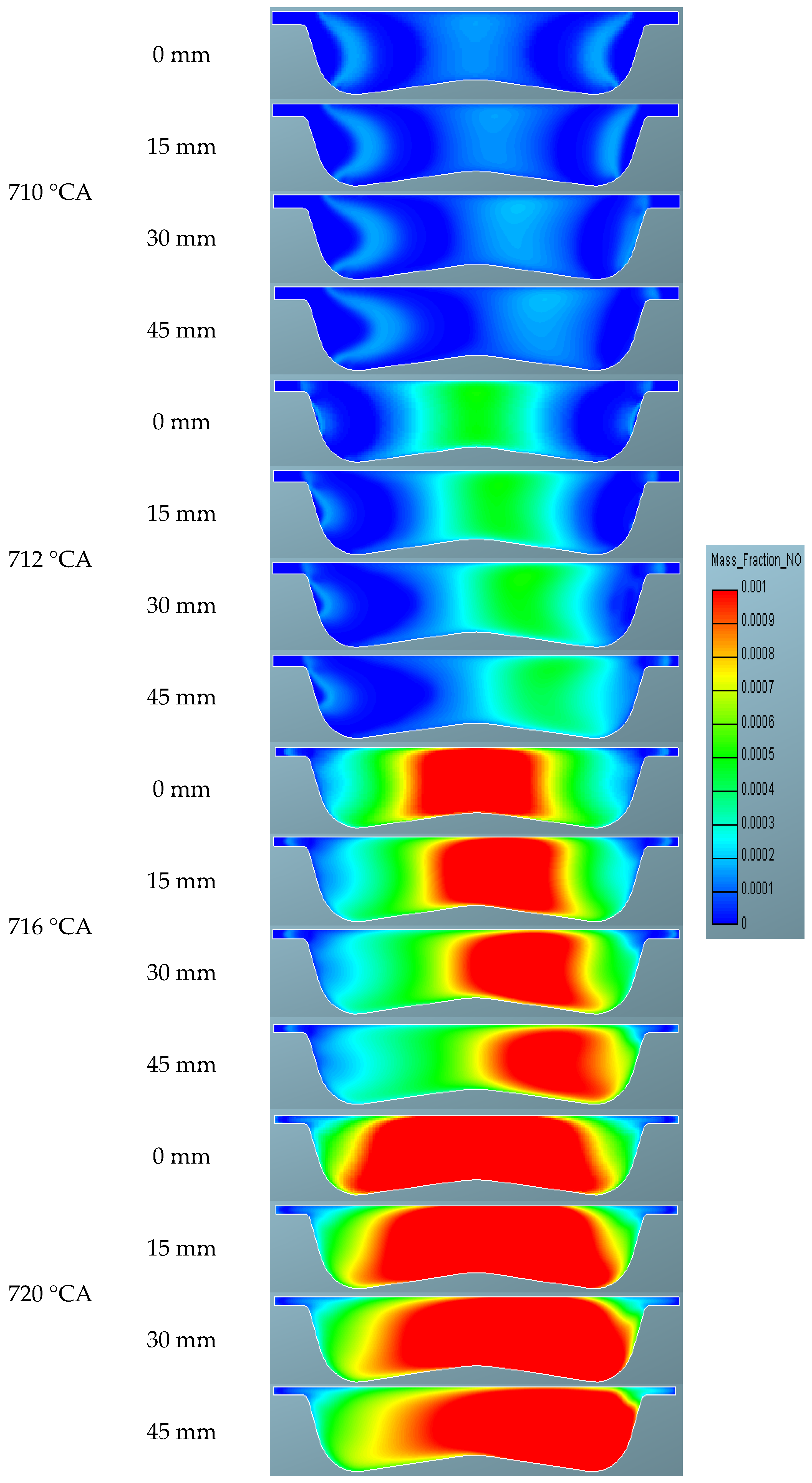
3.3. The Influence of Laser Ignition Transverse Position on Methanol Engine Performance

The transverse positioning of the laser ignition system requires comprehensive consideration of the structural layout of the engine cylinder head. Above the center of the cylinder, components such as the valve train and fuel injection system need to be arranged. To accommodate the laser ignition device, it is necessary to consider that the cylinder head wall thickness in this area is relatively thin. Therefore, after weighing the influence of the transverse position of the laser ignition on the in-cylinder combustion process and engine performance, this paper conducts a comparative simulation study with the laser ignition positioned at four transverse locations: 0 mm, 15 mm, 30 mm, and 45 mm. The laser ignition side position table is shown in Table 5.
Figure 23 and Figure 24 present a comparison of in-cylinder pressure and temperature at different laser transverse positions. It can be observed that the changes in pressure and temperature within the cylinder are relatively small when the transverse position of the laser ignition varies. Only when the transverse position reaches 30 mm or above do the onset points of pressure and temperature rise slightly earlier. The fundamental reason why lateral position variations minimally affect combustion lies in the approximate symmetry of turbulent fields formed by both tumble flow and squish flow when adjusting the laser lateral position within the central area of the combustion chamber. Regardless of flame kernel location, it experiences similar turbulence intensity and mixture concentration, resulting in insignificant differences in flame propagation rate and heat release patterns.
Figure 25 and Figure 26 present a comparison of the instantaneous heat release rate and cumulative heat release within the cylinder at different laser transverse positions. It can be seen that when the transverse position of the laser ignition varies within 15 mm, the heat release rate curve and cumulative heat release are essentially identical to those when the laser ignition is located at the center of the cylinder. The fundamental reason why combustion characteristics remain unchanged at lateral positions ≤15 mm lies in the minimal transverse concentration gradient within the central region after methanol spray evaporation, where fuel distribution uniformity ensures chemical reaction rates remain unaffected by lateral position variations. As the laser transverse position continues to shift, reaching 30 mm or above, the ignition delay period shortens, and the onset of heat release occurs earlier. However, the peak heat release rate at 30 mm and 45 mm decreases to some extent. A comprehensive analysis indicates that the influence of the laser transverse position shift on the combustion state within the cylinder is relatively small.
Figure 27 and Figure 28 present a comparison of in-cylinder NO and Soot emissions at different laser transverse positions. It can be observed that the sensitivity of NO and Soot emissions to changes in the transverse position of the laser ignition is relatively small, with the results being largely consistent across various offset conditions.
Figure 29 presents a comparison of in-cylinder temperature contours at different laser ignition transverse positions. It can be seen that as the longitudinal depth of the laser ignition increases, the location where the ignition kernel forms gradually shifts away from the cylinder centerline, indicating that the formation of the ignition kernel is related to the transverse position of the laser ignition. In the early stages of kernel formation, there are significant differences in flame development within the cylinder, but in the mid to late stages of combustion, the flame covers almost the entire cylinder area, and the flame propagation speed is essentially uniform.
Figure 30 and Figure 31 show comparisons of in-cylinder methanol concentration contours and NO emissions at different laser ignition transverse positions. The distribution of methanol concentration and NO emissions generally aligns with the development of the initial laser ignition depth. By the end of combustion, almost all of the methanol fuel in the cylinder has been consumed, and the combustion speed and saturation are also essentially consistent. The distribution of NO emissions tends to shift towards the ignition position, but the overall quantitative difference in distribution is relatively small. The distribution characteristics of methanol concentration and NO emissions are such that even though eccentric ignition causes non-uniform local mixture consumption, and high-temperature gases during the expansion stroke promote residual methanol oxidation through turbulent diffusion and convective transport, the distribution morphology retains its initial deviation characteristics.

4. Conclusions

This paper investigates the influence of different ignition energies on the ignition performance of a methanol engine, as well as the effects of varying ignition depth and offset positions on the combustion and emission characteristics of the methanol engine under an appropriate laser energy level. By analyzing the data obtained from the simulation, the following conclusions are drawn:
(1) The magnitude of the ignition energy is crucial to the performance of a methanol engine. Insufficient energy can lead to misfires, unstable operation, and poor consistency, while excessive energy results in wasted ignition energy and redundant ignition system design. In this study, five ignition energy levels of 20 mJ, 40 mJ, 60 mJ, 80 mJ, and 100 mJ were selected to investigate the ignition performance of the methanol engine. It was found that stable combustion requires an ignition energy of at least 60 mJ, and when the ignition energy exceeds 80 mJ, the combustion state no longer significantly changes with further increases in energy. Experimental data showing the 60 mJ threshold aligns with the energy requirement for laminar-to-turbulent flame transition. When energy reaches 60 mJ, the flame kernel radius can exceed the quenching distance to establish self-sustaining combustion. Calculations reveal that 60 mJ energy generates flame kernels approximately 4 mm in diameter, fulfilling the developmental requirements for turbulent flames. Therefore, considering both engine operational stability and the lean design of ignition energy, it is recommended to use a laser with an ignition energy of around 80 mJ.
(2) The longitudinal position depth of laser ignition has a critical impact on the structural arrangement of the laser generator, the design of the valve motion profile, and the design of the piston clearance height. A reasonable placement of the longitudinal position of the laser ignition kernel is conducive to improving ignition success rates and reducing the likelihood of engine misfires. With a laser energy of 80 mJ, this study investigated three different longitudinal depths for laser ignition: 5 mm, 15 mm, and 25 mm. It was found that the ignition delay period was significantly shortened, and the combustion speed was faster at the longitudinal depths of 15 mm and 25 mm, but at the same time, NO emissions also increased markedly. Compared to the 25 mm laser longitudinal depth, the flame propagation speed was faster in the late combustion stage at the 15 mm depth, and the concentration of residual methanol fuel in the combustion chamber was lower. The 15 mm position places the initial flame kernel within the central volumetric zone of the combustion chamber, enabling the flame front to expand in near-spherical wave form, whereas the 25 mm position situates the flame kernel near the squish flow region, causing early-stage flame propagation to encounter wall quenching effects and resulting in increased unburned mixture during late combustion phase. Therefore, considering all factors, it is recommended to use 15 mm as the longitudinal position for laser ignition.
(3) The lateral position arrangement of laser ignition needs to take into account the structural layout of the engine cylinder head. In this study, four different lateral positions for laser ignition were investigated: 0 mm, 15 mm, 30 mm, and 45 mm. It was found that changes in the lateral position of the laser had a relatively small impact on the engine’s combustion and emission performance, with the results of each scenario tending to be consistent. Therefore, in the future, the lateral position of laser ignition can be freely adjusted according to different structural layouts.

Author Contributions

X.L.: Writing—original draft, Investigation; J.Z.: Software, Data curation; Z.W.: Writing—review and editing, Methodology, Funding acquisition. All authors have read and agreed to the published version of the manuscript.

Funding

Supported by the National Key R&D program of China (Grant No. 2022YFB4300701, December 2022–November 2026) and the National Key R&D program of China (Grant No. 2022YFB4300704, December 2022–November 2026).

Data Availability Statement

The original contributions presented in this study are included in the article. Further inquiries can be directed to the corresponding author.

Conflicts of Interest

The author declares that there are no conflicts of interest regarding the publication of this paper.

References

  1. Sun, W.; Jiang, M.; Guo, L.; Zhang, H.; Jia, Z.; Qin, Z.; Zeng, W.; Lin, S.; Zhu, G.; Ji, S.; et al. Numerical study of injection strategies for marine methanol/diesel direct dual fuel stratification engine. J. Clean. Prod. 2023, 421, 138505. [Google Scholar] [CrossRef]
  2. Tan, D.; Meng, Y.; Tian, J.; Zhang, C.; Zhang, Z.; Yang, G.; Cui, S.; Hu, J.; Zhao, Z. Utilization of renewable and sustainable diesel/methanol/n-butanol (DMB) blends for reducing the engine emissions in a diesel engine with different pre-injection strategies. Energy 2023, 269, 126785. [Google Scholar] [CrossRef]
  3. Yousefi, A.; Guo, H.; Dev, S.; Liko, B.; Lafrance, S. Effect of pre-main-post diesel injection strategy on greenhouse gas and nitrogen oxide emissions of natural gas/diesel dual-fuel engine at high load conditions. Fuel 2021, 302, 121110. [Google Scholar] [CrossRef]
  4. Yin, X.; Li, W.; Duan, H.; Duan, Q.; Kou, H.; Wang, Y.; Yang, B.; Zeng, K. A comparative study on operating range and combustion characteristics of methanol/diesel dual direct injection engine with different methanol injection timings. Fuel 2023, 334, 126646. [Google Scholar] [CrossRef]
  5. Dimitriou, P.; Javaid, R. A review of ammonia as a compression ignition engine fuel. Int. J. Hydrogen Energy 2020, 45, 7098–7118. [Google Scholar] [CrossRef]
  6. Duan, Q.; Kou, H.; Li, T.; Yin, X.; Zeng, K.; Wang, L. Effects of injection and spark timings on combustion, performance and emissions (regulated and unregulated) characteristics in a direct injection methanol engine. Fuel Process. Technol. 2023, 247, 107758. [Google Scholar] [CrossRef]
  7. Xu, C.; Fang, D.; Luo, Q.; Ma, J.; Xie, Y. A comparative study of laser ignition and spark ignition with gasoline–air mixtures. Opt. Laser Technol. 2014, 64, 343–351. [Google Scholar] [CrossRef]
  8. Kumar, D.; Agarwal, A.K. Laser ignition versus conventional spark ignition system performance for hydrogen-enriched natural gas-air mixtures in a constant volume combustion chamber. Appl. Therm. Eng. 2024, 257, 123988. [Google Scholar] [CrossRef]
  9. Srivastava, D.K.; Agarwal, A.K. Comparative experimental evaluation of performance, combustion and emissions of laser ignition with conventional spark plug in a compressed natural gas fuelled single cylinder engine. Fuel 2014, 123, 113–122. [Google Scholar] [CrossRef]
  10. Azarmanesh, S.; Targhi, M.Z. Comparison of laser ignition and spark plug by thermodynamic simulation of multi-zone combustion for lean methane-air mixtures in the internal combustion engine. Energy 2021, 216, 119309. [Google Scholar] [CrossRef]
  11. Sun, W.; Zeng, W.; Guo, L.; Zhang, H.; Yan, Y.; Lin, S.; Zhu, G.; Jiang, M.; Yu, C.; Wu, F. An optical study of the combustion and flame development of ammonia-diesel dual-fuel engine based on flame chemiluminescence. Fuel 2023, 349, 128507. [Google Scholar] [CrossRef]
  12. Pei, Y.; Wang, D.; Jin, S.; Gu, Y.; Wu, C.; Wu, B. A quantitative study on the combustion and emission characteristics of an Ammonia-Diesel Dual-fuel (ADDF) engine. Fuel Process. Technol. 2023, 250, 107906. [Google Scholar] [CrossRef]
  13. Xinlei, L.; Sage, K.; Hu, W.; Mingfa, Y. A comparative numerical investigation of reactivity controlled compression ignition combustion using large eddy simulation and reynolds-averaged navier-stokes approaches. Fuel 2022, 257, 116023. [Google Scholar]
  14. Shi, X.R.; Xiong, Q.; Pan, C.Y.; Liu, L.; Fu, S.Y.; Zhao, J.H. Effect of ammonia energy fraction and injection strategy on the combustion and emission of dual-fuel low-speed engine. J. Int. Combust. Eng. 2024, 42, 489–498. [Google Scholar]
  15. Han, Z.; Reitz, R.D. Turbulence modeling of internal combustion engines using RNG k-ε models. Combust Sci. Technol. 1995, 106, 267–295. [Google Scholar] [CrossRef]
  16. Dec, J.E.; Reltz, R.D. Comparisons of diesel spray liquid penetration and vapor fuel distributions with in-cylinder optical measurements. J. Eng. Gas. Turb. Power 2000, 122, 588–595. [Google Scholar]
  17. Han, Z.; Reitz, R.D. A temperature wall function formulation for variable-density turbulent flows with application to engine convective heat transfer modeling. Int. J. Heat Mass Tran. 1997, 40, 613–625. [Google Scholar] [CrossRef]
  18. Schmidt, D.P.; Rutland, C.J. A new droplet collision algorithm. J. Comput. Phys. 2000, 164, 62–80. [Google Scholar] [CrossRef]
  19. O’Rourke, P.J.; Amsden, A.A. A spray/wall interaction submodel for the KIVA-3 wall film model. J. Engines 2000, 109, 281–298. [Google Scholar]
  20. Senecal, P.K.; Pomraning, E.; Richards, K.J.; Briggs, T.E.; Choi, C.Y.; McDavid, R.M.; Patterson, M.A. Multi-dimensional modeling of direct-injection diesel spray liquid length and flame lift-off length using cfd and parallel detailed chemistry. J. Engines 2003, 112, 1331–1351. [Google Scholar]
  21. Maroteaux, F.; Saad, C. Combined mean value engine model and crank angle resolved in-cylinder modeling with NOx emissions model for real-time diesel engine simulations at high engine speed. Energy 2015, 88, 515–527. [Google Scholar] [CrossRef]
  22. Wang, H.; Wang, B.; Yang, C.; Hu, D.; Duan, B.; Wang, Y. Study on dual injection strategy of diesel ignition ammonia/hydrogen mixture fuel engine. Fuel 2023, 348, 128526. [Google Scholar] [CrossRef]
  23. Mi, S.; Wu, H.; Pei, X.; Liu, C.; Zheng, L.; Zhao, W.; Qian, Y.; Lu, X. Potential of ammonia energy fraction and diesel pilot-injection strategy on improving combustion and emission performance in an ammonia-diesel dual fuel engine. Fuel 2023, 343, 127889. [Google Scholar] [CrossRef]
  24. Li, T.; Zhou, X.; Wang, N.; Wang, X.; Chen, R.; Li, S.; Yi, P. A comparison between low-and high-pressure injection dual-fuel modes of diesel-pilot-ignition ammonia combustion engines. J. Energy Inst. 2022, 102, 362–373. [Google Scholar] [CrossRef]
  25. Shin, J.; Park, S. Numerical analysis for optimizing combustion strategy in an ammonia-diesel dual-fuel engine. Energy Convers. Manag. 2023, 284, 116980. [Google Scholar] [CrossRef]
  26. Pochet, M.; Jeanmart, H.; Contino, F. A 22: 1 compression ratio ammonia-hydrogen HCCI engine: Combustion, load, and emission performances. Front. Mech. Eng. 2020, 6, 43. [Google Scholar] [CrossRef]
  27. Xuan, T.; Sun, Z.; EL-Seesy, A.I.; Mi, Y.; Zhong, W.; He, Z.; Wang, Q.; Sun, J.; El-Batsh, H.M.; Cao, J. An optical study on spray and combustion characteristics of ternary hydrogenated catalytic biodiesel/methanol/n-octanol blends; part II: Liquid length and in-flame soot. Energy 2021, 227, 120543. [Google Scholar] [CrossRef]
Figure 1. Main Process of Methanol Oxidation Reaction.
Energies 18 02119 g001
Figure 2. (a) MAN L23/30H four-stroke diesel engine. (b) Three-dimensional mesh of engine combustion model.
Energies 18 02119 g002
Figure 3. (a) The top dead center (TDC); (b) bottom dead center (BDC).
Energies 18 02119 g003
Figure 4. Grid division strategy.
Energies 18 02119 g004
Figure 5. Comparison of the experimental and simulated values.
Energies 18 02119 g005
Figure 6. (a) Relationship between engine cylinder pressure and crankshaft angle under different ignition energy states. (b) Relationship between engine cylinder temperature and crankshaft angle under different ignition energy states.
Energies 18 02119 g006
Figure 7. Relationship between combustion exothermic rate and crankshaft angle under different ignition energy states.
Energies 18 02119 g007
Figure 8. Relationship between the accumulated heat discharge and the crankshaft angle under different ignition energy states.
Energies 18 02119 g008
Figure 9. Relationship between engine NO emissions and crankshaft angle under different ignition energy states.
Energies 18 02119 g009
Figure 10. Relationship between engine Soot emissions and crankshaft angles under different ignition energy states.
Energies 18 02119 g010
Figure 11. Distribution of engine cylinder temperature in 80 mJ ignition energy.
Energies 18 02119 g011
Figure 12. Distribution of methanol under the state of 80 mJ ignition energy.
Energies 18 02119 g012
Figure 13. NO cloud map distribution under the state of 80 mJ ignition energy.
Energies 18 02119 g013
Figure 14. Relationship between the pressure emission with the crankshaft angle at different laser ignition longitudinal positions.
Energies 18 02119 g014
Figure 15. Relationship between the temperature and the angle of the crankshaft at different laser ignition longitudinal positions.
Energies 18 02119 g015
Figure 16. Relationship between instantaneous combustion exothermic rate and crankshaft angle at different laser ignition longitudinal positions.
Energies 18 02119 g016
Figure 17. Relationship between the accumulated exothermic heat of combustion with the angle of the crankshaft at different laser ignition longitudinal positions.
Energies 18 02119 g017
Figure 18. Relationship between no emissions and the angle of the crankshaft at different laser ignition longitudinal positions.
Energies 18 02119 g018
Figure 19. Relationship between soot emissions and the angle of the crankshaft at different laser ignition longitudinal positions.
Energies 18 02119 g019
Figure 20. Comparison of the distribution of the temperature at different longitudinal positions of laser ignition.
Energies 18 02119 g020
Figure 21. Comparison of methanol cloud distribution at different laser ignition longitudinal positions.
Energies 18 02119 g021
Figure 22. Comparison of NO emission cloud map distribution at different laser ignition longitudinal positions.
Energies 18 02119 g022
Figure 23. Comparison of engine cylinder pressure at different laser ignition lateral positions.
Energies 18 02119 g023
Figure 24. Comparison of engine cylinder temperature at different laser ignition transverse positions.
Energies 18 02119 g024
Figure 25. Comparison of combustion exothermic rates at different laser ignition transverse positions.
Energies 18 02119 g025
Figure 26. Comparison of cumulative heat release at different laser ignition lateral positions.
Energies 18 02119 g026
Figure 27. Comparison of no emissions in the engine cylinder at different laser ignition transverse positions.
Energies 18 02119 g027
Figure 28. Comparison of Soot emissions in the engine cylinder at different laser ignition lateral positions.
Energies 18 02119 g028
Figure 29. Comparison of temperature distribution at different laser ignition lateral positions.
Energies 18 02119 g029
Figure 30. Comparison of methanol concentration distribution at different laser ignition lateral positions.
Energies 18 02119 g030
Figure 31. Comparison of NO emission distribution during different laser ignition transverse positions.
Energies 18 02119 g031
Table 1. Engine specifications.
ParameterValue
Cylinder diameter 225 and 300 mm
MCR Output175 kW
MCR rotational speed900 rpm
Compression Ratio 13.6
Piston area per cylinder398 cm2
Piston velocity9 m/s
Swept volume during piston operation11.8 L
MCR fuel consumption194 g/kWh
IMEP19.7 bar
MCP151 bar
Table 2. Selection of simulation submodel.
Physical Model NameSubmodel Settings
Turbulence modelRNG k-ε [15]
Spray breakup modelKH-RT [16]
Wall heat transfer modelHan and Reitz model [17]
Spray collision modelNTC collision [18]
Drop turbulent dispersion model Wall Film-O’Rourke [19]
Combustion modelSAGE [20]
Carbon smoke emission modelHiroyasu soot [21]
NOx formation modelExtended Zeldovich [22]
Table 3. List of laser ignition energies.
NumberLaser Energy (mJ)Laser Longitudinal Position (mm)
1205~6
2405~6
3605~6
4805~6
51005~6
Table 4. List of laser ignition vertical positions.
NumberLaser Energy (mJ)Laser Longitudinal Position (mm)
1805~6
28015~16
38025~26
Table 5. Laser ignition lateral position list.
NumberLaser Energy (mJ)Laser Transverse Position (mm)
1800
28015
38030
48045
Disclaimer/Publisher’s Note: The statements, opinions and data contained in all publications are solely those of the individual author(s) and contributor(s) and not of MDPI and/or the editor(s). MDPI and/or the editor(s) disclaim responsibility for any injury to people or property resulting from any ideas, methods, instructions or products referred to in the content.

