Article

Research on the Characteristics of a Range-Extended Hydraulic–Electric Hybrid Drive System for Tractor Traveling Systems

College of Mechanical Engineering, Taiyuan University of Technology, Taiyuan 030024, China
*
Author to whom correspondence should be addressed.
Energies 2025, 18(8), 2075; https://doi.org/10.3390/en18082075
Submission received: 31 March 2025 / Revised: 14 April 2025 / Accepted: 16 April 2025 / Published: 17 April 2025

Abstract

Pure electric tractors face challenges in complex operating conditions, including the excessive peak motor torque caused by frequent start–stop cycles and insufficient energy utilization. To address these issues, this study proposes a hydraulic–electric hybrid drive system for tractor traveling systems which is based on a range-extended hybrid architecture. By combining the high-torque characteristics of hydraulic drive systems with the high control precision of electric motors, a hydraulic–electric dual-power coupling model was constructed. A logic-threshold-based operating mode division strategy and a hierarchical braking energy recovery mechanism were developed. The start–stop control dynamics and energy recovery efficiency of the system during plowing and transport operations were thoroughly analyzed. The simulation results demonstrate that while maintaining its acceleration and braking performance, the proposed system achieves 18.8% and 35.7% reductions in its peak motor torque during plowing and transport operations, respectively. Its braking energy recovery efficiency improved to 48.3% and 66.4% in the two scenarios; 18.5% and 25.7% reductions in overall energy consumption were seen.

1. Introduction

With the increasing level of agricultural mechanization occurring, agricultural production models are undergoing a profound transformation. Driven by sustainable development strategies, the electrification of agricultural machinery has become an inevitable trend [1]. As a core component of agricultural machinery, tractors have emerged as a major challenge in environmental governance due to their emission of pollutants [2,3]. Although pure electric tractors achieve zero emissions, the limited endurance of these high-power tractors and inadequate charging infrastructure severely restrict their operational efficiency, hindering their widespread adoption [4]. The integration of hybrid powertrain technology with high-power tractors serves as an ideal solution for transitioning from traditional diesel tractors to fully electric ones [5]. Current research on improving the fuel economy of hybrid tractors primarily focuses on two aspects: energy management strategies and the optimization of transmission systems and power sources [6,7].
Under field operation and high-speed transport conditions, energy management strategies effectively balance fuel economy and power performance to address fluctuating load demands [8]. Francesco adopted a Physical Network (PN) modeling approach, comparing traditional diesel tractors with parallel hybrid tractors and achieving a 16% reduction in average fuel consumption [9]. Zhang et al. proposed a globally optimal energy management strategy based on dynamic programming to enhance the energy efficiency of agricultural hybrid tractors equipped with continuously variable transmissions (CVTs), ensuring optimal operating regions for both diesel engines and electric motors, thereby significantly reducing energy consumption [10]. Wang et al. developed a coordinated optimization energy management strategy for dual-motor-driven tractors, improving their operational efficiency and stability during typical scenarios such as plowing and transport [11]. Li et al. introduced an improved dung beetle algorithm-optimized multi-fuzzy-control energy management strategy, enabling continuous torque adjustment between the engine and motor, leading to reductions in both SOC fluctuations and fuel consumption [12]. Li et al. proposed a load-adaptive hybrid power supply system (battery/supercapacitor) for pure electric tractors using dynamic programming algorithms, effectively minimizing the total energy losses in the power supply system [13,14]. Zhao et al. designed an energy management strategy for hybrid tractors that combined fuel cells, lithium batteries, and supercapacitors, maximizing the external energy output while further improving the system’s fuel economy and fuel cell durability [15]. Zhao et al. addressed the insufficiency of traditional energy management strategies in maintaining dynamic system power by formulating a fuzzy-following energy management strategy which demonstrated superior operational efficiency and fuel economy for tractors in plowing conditions [16].
The optimization of transmission systems and power sources primarily focuses on three hybrid configurations: series, parallel, and power-split hybrids [17]. Manuel et al. designed a series hybrid tractor model, optimizing its control and component sizing while considering environmental and economic factors, demonstrating that hybrid configurations achieve a higher average efficiency than traditional setups [18]. Li et al. developed a dual-input coupled powertrain system and proposed a parameter-matching method, improving the overall energy efficiency of tractors by 9.8% under plowing conditions [19,20]. Claudio et al. adapted automotive industry solutions to propose a hybrid transmission system with an electric continuously variable transmission (e-CVT), optimizing the tractor’s layout and achieving significant energy savings [21]. Quan et al. introduced an electro-hydraulic dual-power coordinated drive scheme for heavy-duty linear actuators and high-inertia rotary systems, combining high power density, precise control, and energy efficiency for remarkable energy conservation [22,23]. Li et al. applied this principle to heavy-duty robotic arms, proposing an electro-hydraulic hybrid active–passive system integrated with potential energy recovery and reuse, further enhancing energy efficiency [24]. Li et al. presented a hybrid electro-hydraulic powertrain structure that included planetary gear mechanisms and combined driving mode recognition with fuzzy control to actively regulate the distribution of energy between the motor and hydraulic pump/motor [25]. Although hydraulic–electric hybrid drive technology has been used in construction machinery, there exist fundamental differences in its design objectives and operational scenarios compared to tractors. Hydraulic systems in construction machinery are primarily designed for short-term, intermittent, high-power outputs, with energy recovery focusing on potential energy storage [26]. In contrast, tractors face unique challenges during field operations, including frequent start–stop cycles, prolonged continuous operation, high-inertia loads, and dynamic torque demands, along with their alternation between transport and plowing operations.
To address the aforementioned challenges, a range-extended hydraulic–electric hybrid drive system for tractor traveling systems is proposed. This solution is built around a range-extended hybrid powertrain, which is integrated with a hydraulic system and supplemented by an electric motor drive, significantly enhancing the tractor’s power performance and energy utilization efficiency. Based on the torque demand characteristics of tractors, a control strategy for start–stop and braking operations is formulated, and the system is analyzed through simulations conducted under two typical working conditions: plowing and transport operations.
This paper is structured as follows: Section 2 primarily describes the research methods and ideas put forward by this research. Section 3 elaborates on the system architecture of the hybrid tractor, with a detailed analysis of the operating principles of the hydraulic–electric hybrid drive traveling system. Section 4 establishes simulation models for key components of the hybrid tractor. Section 5 proposes a logic-threshold-based operating mode division strategy and a hierarchical braking energy recovery mechanism, building a multidisciplinary co-simulation model on the SimulationX (4.1) platform. Section 6 validates the system’s start–stop dynamic characteristics and energy recovery efficiency in plowing and transport scenarios through conducting simulations. Section 7 summarizes our research findings and draws conclusions.

2. Materials and Methods

This study focuses on a range-extended hydraulic–electric hybrid tractor, addressing the issues of excessive peak motor torque and insufficient energy utilization under complex working conditions by proposing a dual-power coupling drive system that integrates hydraulic and electric technologies. The system consists of three modules: a range extender generation module, an electric drive module, and a hydraulic drive module. Specifically, the range extender employs an integrated methanol engine–generator design; the electric drive system includes a battery pack and traction motor; and the hydraulic drive system achieves peak torque compensation and braking energy recovery through an accumulator pump/motor unit.
The simulation model, developed on the SimulationX platform, includes multiple submodels: a driver model, range extender model, battery model, traction motor model, and longitudinal dynamics model. The driver model adopts a PI control strategy to regulate the pedal position based on the deviations between target and actual vehicle speeds. The range extender model determines the methanol engine’s fuel consumption via 2D lookup tables and calculates the generated power considering the generator’s efficiency characteristics. The battery model utilizes an equivalent internal resistance method, ignoring temperature effects, to estimate SOC variations through open-circuit voltage and internal resistance properties. The traction motor model is interpolated from efficiency maps with distinct driving/generating modes. The longitudinal dynamics model establishes traction force equations for two typical scenarios: plowing operations, in which rolling resistance, aerodynamic drag, and plowing resistance are considered, and transportation operations, which include acceleration resistance and gradient resistance as well.
For control strategies, a logic-threshold-based operational mode division strategy and a hierarchical braking energy recovery mechanism are proposed. The system dynamically switches between five modes (parking, hydraulic–electric hybrid drive, braking energy recovery, pure electric drive, and range-extended mode) based on pedal position, vehicle speed, and SOC thresholds. The three-stage braking energy recovery prioritizes hydraulic system regeneration for high-power recovery (stored via accumulators), followed by motor regeneration and mechanical braking. Our simulation experiments compare the dynamic characteristics and energy consumption of pure electric and hybrid systems under the following conditions: Plowing operation, with a 0–8 km/h speed cycle and start–stop sequences; transportation operation, with a 0–45 km/h speed cycle.

3. System Composition of Hybrid Tractor

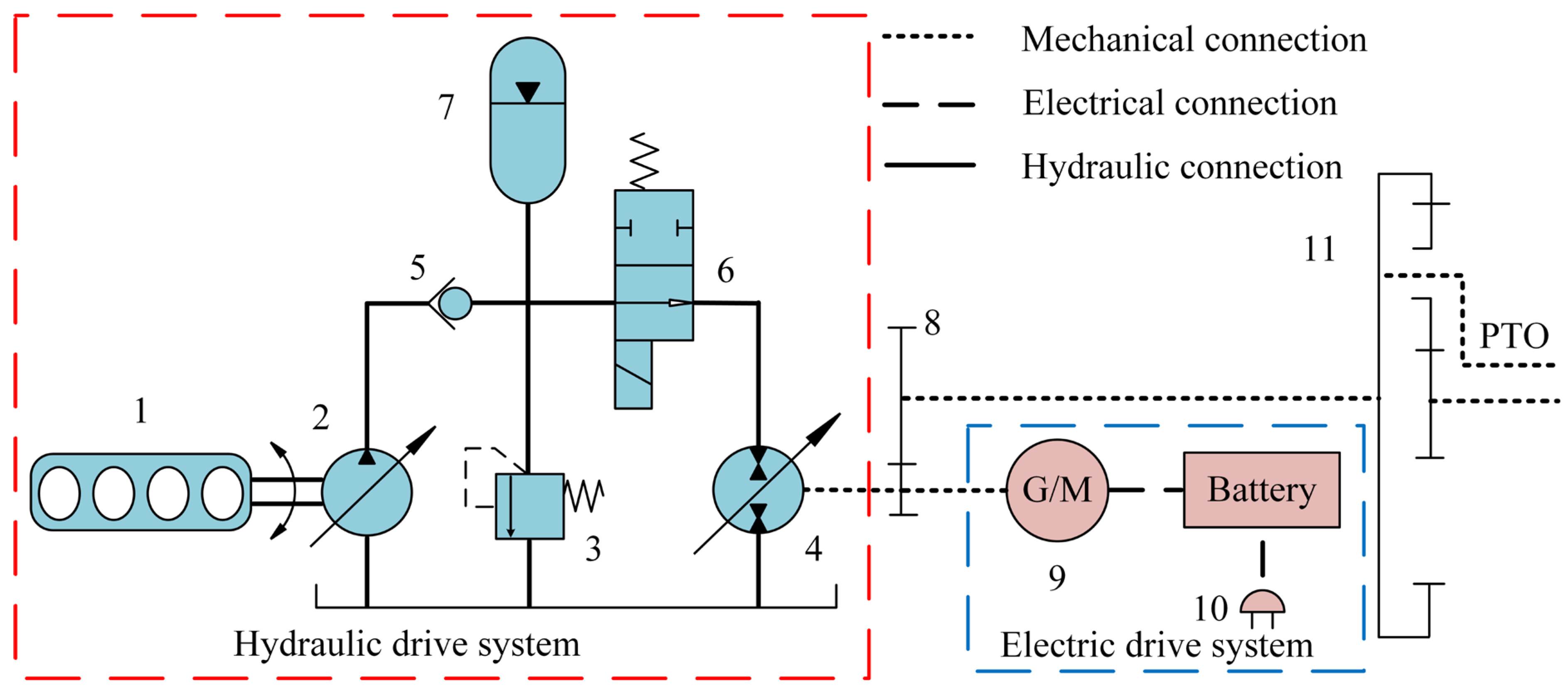
3.1. Hybrid System Composition

The traveling system of the hybrid tractor adopts a range-extended hybrid architecture. As illustrated in Figure 1, the powertrain comprises three modules: the range extender generation module, the electric drive module, and the hydraulic drive module. The range extender integrates a methanol engine with a generator, which is optimized to maintain the continuous operation of the engine within its high-efficiency zone, while the generator charges the traction battery using its electrical output. The electric drive system includes a battery pack, rectifier, and drive motor, where the drive motor serves as the primary power source that directly drives the wheels. The hydraulic drive system employs an accumulator–hydraulic pump/motor unit to provide peak torque compensation during the startup phase and enable kinetic energy recovery during braking. These two powertrains are dynamically coupled via a planetary gear mechanism for power distribution, with synthesized torque allocated to the traveling mechanism and PTO (Power Take-Off). The technical parameters of the key components are summarized in Table 1.
The key dimensional parameters of the tractor are based on a reference model from John Deere (Moline, IL, USA). The range-extended hybrid system includes the following components: a methanol direct-injection internal combustion range extender produced by Weichai Power (Weifang, China), a high-capacity battery pack from CATL (Ningde, China), a traction motor supplied by Inovance Technology (Shenzhen, China), and axial piston pump/motor units manufactured by Hengli Hydraulic (Changzhou, China).

3.2. Hydraulic–Electric Hybrid Drive System for Tractor Traveling Systems

As illustrated in Figure 2, compared to conventional range-extended hybrid tractors, this tractor introduces a hydraulic drive system into its traveling system, forming a hydraulic–electric hybrid drive system that works in conjunction with its electric drive system. During the stable operation of the tractor, when the battery’s SOC (State of Charge) is high, Methanol Engine 1 drives Hydraulic Pump 2 to replenish oil in Accumulator 6 when its hydraulic pressure is insufficient. During braking conditions, Hydraulic Pump/Motor 3 switches to “pump mode” to recover braking energy into Accumulator 6, while Drive Motor 8 simultaneously operates in power generation mode. When the tractor starts or requires high-power output, Accumulator 6 releases its stored high-pressure oil, and Hydraulic Pump/Motor 3 transitions to “motor mode”, collaborating with Drive Motor 8 to drive the wheels. This operational strategy not only significantly reduces the peak torque demand on the electric motor but also minimizes the installed power capacity of the system, achieving higher energy utilization efficiency.

4. Model of Hybrid Tractor Traveling Systems

4.1. Driver Model

The driver model adopts forward modeling, with the target vehicle speed and actual vehicle speed as inputs, and the accelerator pedal and brake pedal positions as outputs. A PI-based control driver model is constructed, and its principle is illustrated by the following formula:
v ( t ) = v s e t v a c t
u t = k p v ( t ) + k i v ( t ) d t
In these equations, kp is the proportional gain; ki is the integral gain; vset is the target vehicle speed (km/h); vact is the actual vehicle speed (km/h); v(t) is the velocity error between the target and actual speeds (km/h); and ut is the normalized pedal position. When ut ∈ (0,1) the accelerator pedal is activated, and when ut ∈ (−1,0) the brake pedal is engaged.

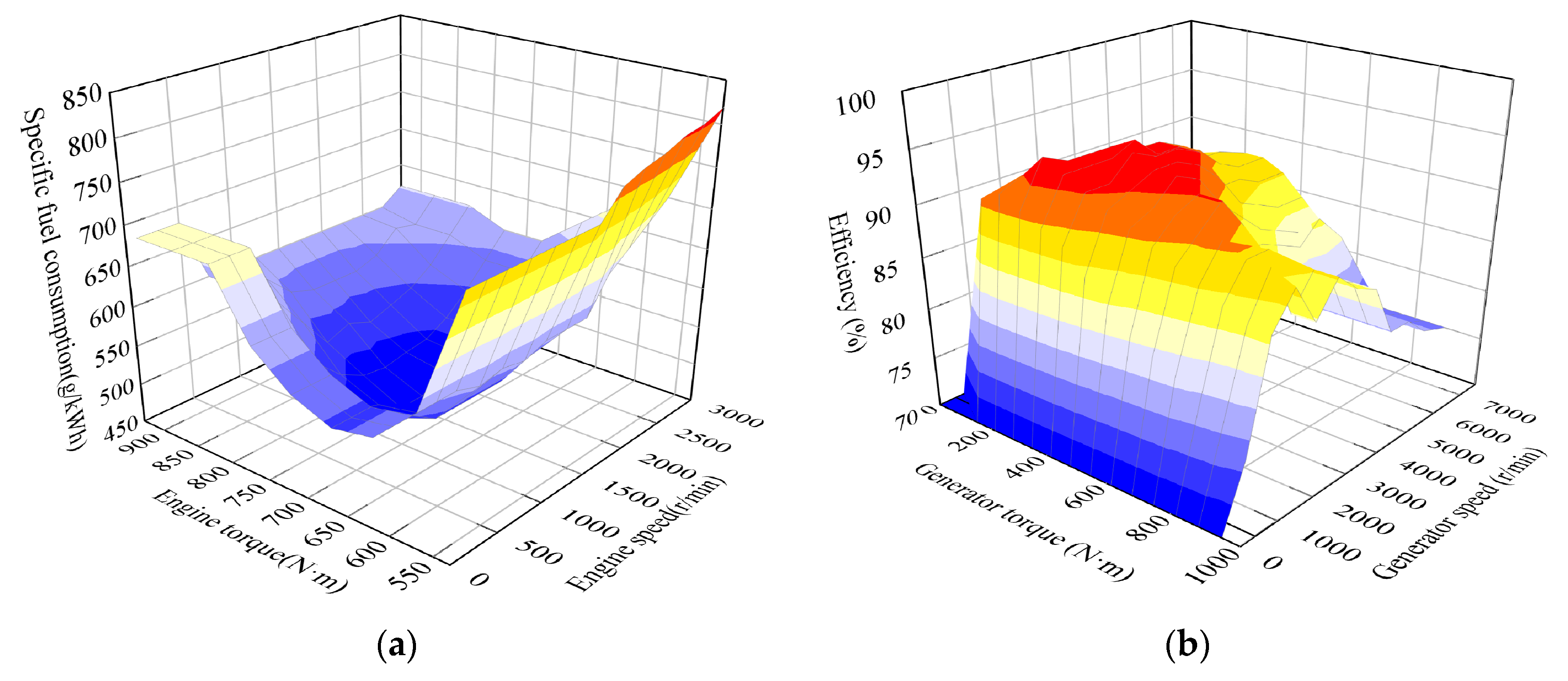
4.2. Range Extender Model

The range extender consists of a methanol-fueled engine and a generator which are mechanically coupled to share identical torque and rotational speeds. By neglecting temperature effects and the generator’s dynamic processes, the engine’s effective fuel consumption rate bfuel (g/kWh) is determined via a two-dimensional lookup table, as illustrated in Figure 3a. The methanol consumption of the engine is calculated using the following formula:
Q = 1 3.6 × 10 6 × ρ 0 t T e n e b f u e l d t
In this formula, Q is the methanol consumed (L); bfuel is the effective fuel consumption rate (g/kWh); Te is the engine torque (N·m); ne is the engine speed (r/min); ρ is the fuel density (g/mL); and t is the time (s).
The generator model is constructed through data interpolation. The generator’s efficiency is shown in Figure 3b and the generator’s power is calculated using the following formula:
P g = T g n g 9550 η g
In this formula, Pg is the generator’s power (kW); Tg is the generator’s torque (N·m); ng is the generator’s speed (r/min); and ηg is the generator’s efficiency (%).

4.3. Battery Model

The traction battery is modeled using an equivalent resistance approach, which is simplified as a series combination of an ideal voltage source Voc and an equivalent internal resistance Rint. To validate the optimization effects of the hydraulic–electric hybrid drive system on the tractor’s fuel economy and energy recovery efficiency—rather than addressing long-term battery durability concerns—battery temperature variations are neglected, as the simulation’s duration is significantly shorter than actual operational times. The relationships between the open-circuit voltage, charging internal resistance, and discharging internal resistance are illustrated in Figure 4. When the battery SOC is below 20%, both its charging and discharging internal resistances increase significantly, resulting in reduced effective energy output. Conversely, when the battery SOC exceeds 80%, a higher charging voltage is required, leading to decreased charging efficiency. The battery achieves optimal energy efficiency when its SOC operates within the 20–80% range. The battery’s output power and State of Charge (SOC) are calculated using the following formulas:
V b a t = V o c I R int P b a t = V b a t I
S O C ( t ) = S O C 0 1 Q e t 0 t I ( t ) d t
In these formulas, Vbat is the battery’s output voltage (V); Voc is the battery’s terminal voltage (V); I is the battery’s charge/discharge current (A); Rint is the battery’s internal resistance (Ω); Pbat is the battery’s output power (kW); Qe is the battery’s rated capacity (A·h); SOC(t) is the SOC value at time t; and SOC0 is the initial SOC value.

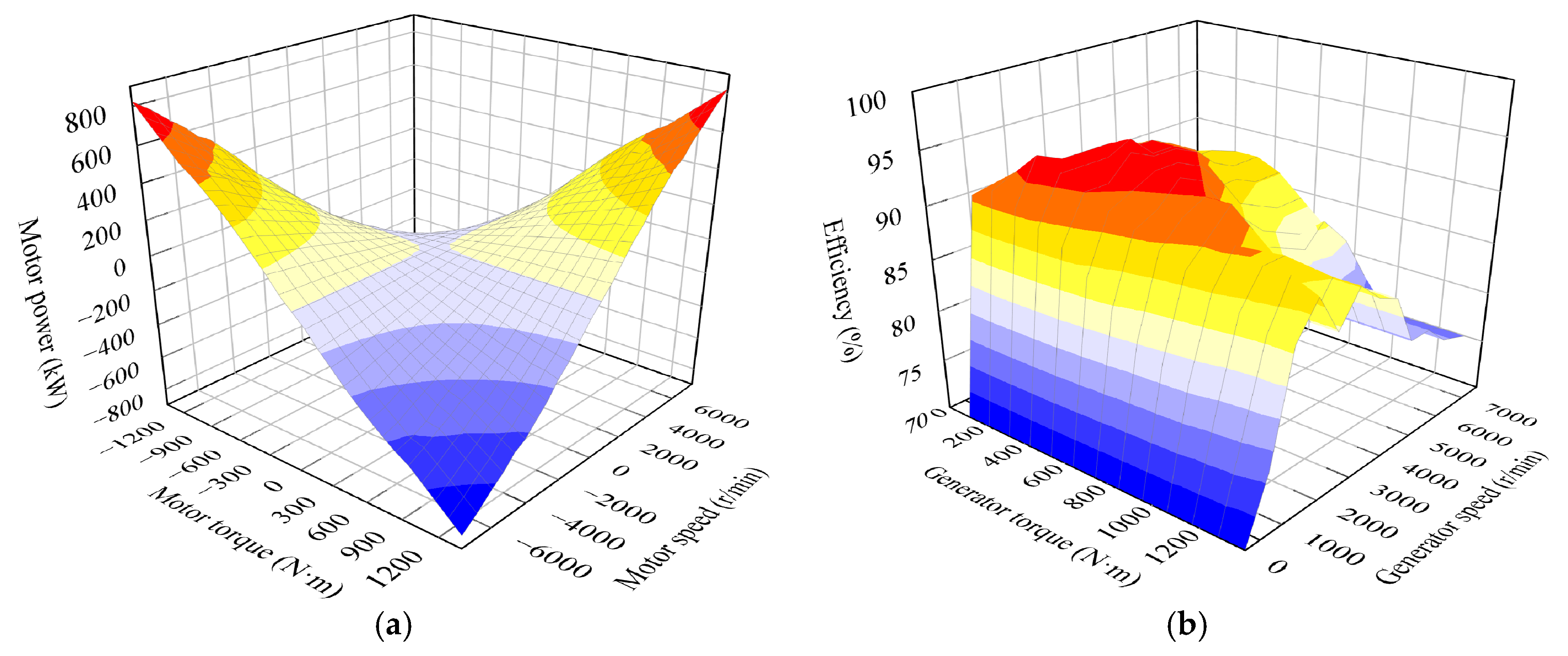
4.4. Drive Motor Model

The drive motor model is constructed through data interpolation. The motor’s efficiency is as shown in Figure 5a. The motor operates in two modes: power generation mode and drive mode. The power of the drive motor is calculated using the following formula, and its power characteristics are depicted in Figure 5b:
P d = T d n d 9550 η d
In this formula, Pd is the drive motor’s power (kW); Td is the drive motor’s torque (N·m); nd is the drive motor’s speed (r/min); and ηd is the drive motor’s efficiency (%).

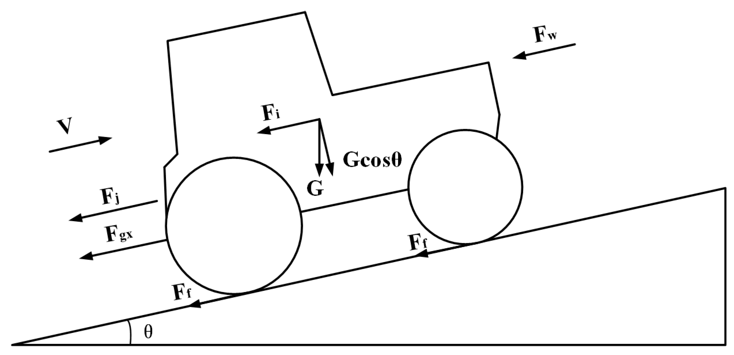
4.5. Longitudinal Dynamics Model of the Tractor

The power performance and fuel economy of the tractor are primarily evaluated using a longitudinal dynamics model. This study focuses on two typical operating scenarios: transport operations and plowing operations. A schematic of the forces acting on the tractor is illustrated in Figure 6.

4.5.1. Dynamics Model of Tractor Plowing Operations

During plowing operations, the tractor’s tractive force primarily depends on rolling resistance, air resistance, and plowing resistance. Due to its low operational speed and the flat terrain in field operations, the effects of acceleration resistance and gradient resistance are temporarily neglected. The tractor’s tractive force is calculated using the following formulas:
F t = F f + F w + F g x
F f = G f cos θ
F w = C D A 21.15 v 2
F g x = ( 1.1 ~ 1.2 ) z b h k
In these formulas, Ft is the tractive force (N); Ff is the rolling resistance (N); Fw is the air resistance (N); Fgx is the plowing resistance (N); G is the tractor’s gravitational force (N); f is the rolling resistance coefficient; θ is the slope angle (°); CD is the air resistance coefficient; A is the frontal area (m2); v is the speed (km/h); z is the number of plowshares; b is the width of a single plowshare (cm); h is the plowing depth (cm); and k is the soil-specific resistance (N/cm2).

4.5.2. Dynamics Model of Tractor Transportation Operations

During transport operations, the tractor’s tractive operation force primarily depends on rolling resistance, air resistance, acceleration resistance, and gradient resistance. The tractive force is calculated using the following formulas:
F t = F f + F w + F i + F j
F i = G sin θ
F j = δ m d v d t
In these formulas, Fi is the gradient resistance (N); Fj is the acceleration resistance (N); m is the tractor mass (N); and δ is the rotational mass conversion coefficient.

5. Establishment of Control Strategy and Co-Simulation Model

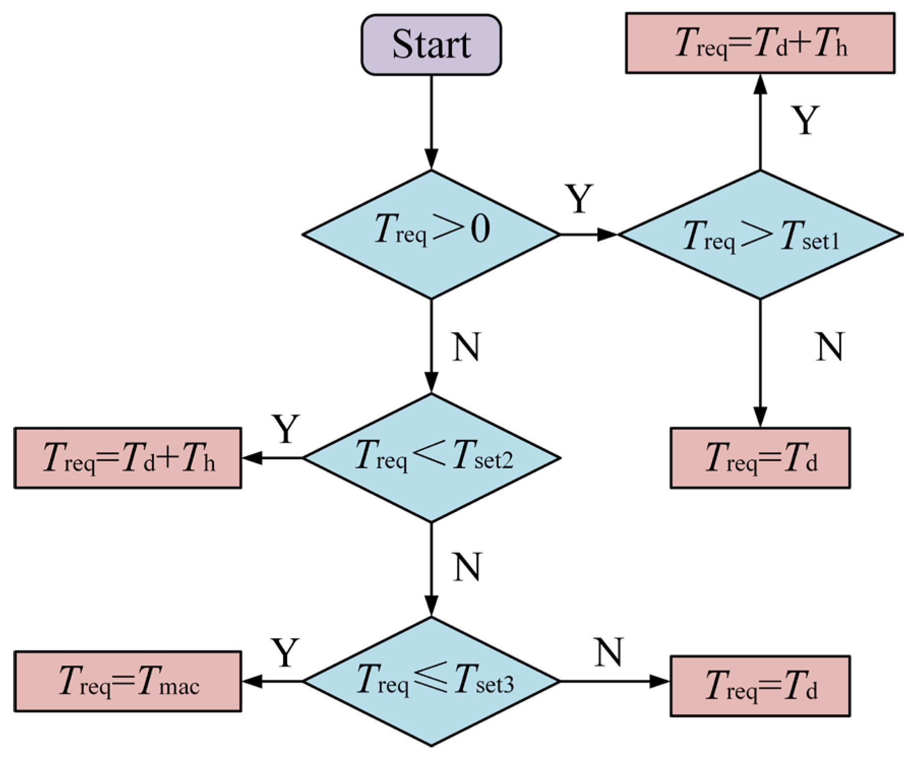
5.1. Control Strategy

The hybrid tractor system has three power sources and operates in five working modes, as listed in Table 2: Parking Mode, Hydraulic–Electric Hybrid Drive Mode, Braking Energy Recovery Mode, Pure Electric Drive Mode, and Range-Extended Mode.
To effectively control switching between the five operating modes of the hybrid tractor, a logic-threshold-based operating mode division strategy is designed, with its flowchart illustrated in Figure 7. Based on the pedal position and tractor speed, the required torque Treq is calculated. The torque threshold Tset = 50 N·m is determined using the engine’s minimum fuel consumption rate map and the drive motor’s efficiency map. To maintain battery performance and longevity, the battery’s SOC (State of Charge) is constrained to within the range of 20–80%. The engine is activated when the SOC falls below the minimum threshold (SOCmin = 20%) and deactivated when the SOC exceeds the maximum threshold (SOCmax = 80%). If the SOC remains between 20% and 80%, the engine retains its previous operating state. Finally, the tractor’s operating mode is determined by the required torque Treq, battery SOC, and torque threshold Tset.
The start–stop process of the tractor during plowing and transport operations requires coordinated action between the hydraulic pump/motor and the electric motor. A hierarchical braking energy recovery mechanism is designed, as shown in Figure 8. First, the operating condition (startup or braking) is determined based on the sign of the required torque Treq. Based on the rated torque of the selected traction motor and the torque required for steady-state operation in plowing and transportation operations, if the speed remains relatively constant with minimal fluctuations, the system exclusively utilizes the motor for startup and braking. The determination of an emergency braking event is made by evaluating the duration of braking, thereby enabling the selection of appropriate logical thresholds. The threshold parameters are defined as follows: Tset1 = 560 N·m (plowing operation); Tset1 = 150 N·m (transportation operation); Tset2 = (−10) N·m; Tset3 = (−600) N·m.
During the startup/acceleration phase, the following conditions apply:
  • If Treq > Tset1 (threshold torque), the hydraulic pump/motor and electric motor jointly drive the wheels.
  • If Treq is relatively low, the electric motor operates independently.
During the braking phase, the following conditions apply:
  • During emergency braking, the mechanical brake provides the braking torque Tmac to ensure safety.
  • If Treq is low, the electric motor alone generates the braking torque Td.
  • If Treq falls within a predefined range, hydraulic regenerative braking is activated, where the hydraulic pump/motor recovers kinetic energy to provide the braking torque Th.

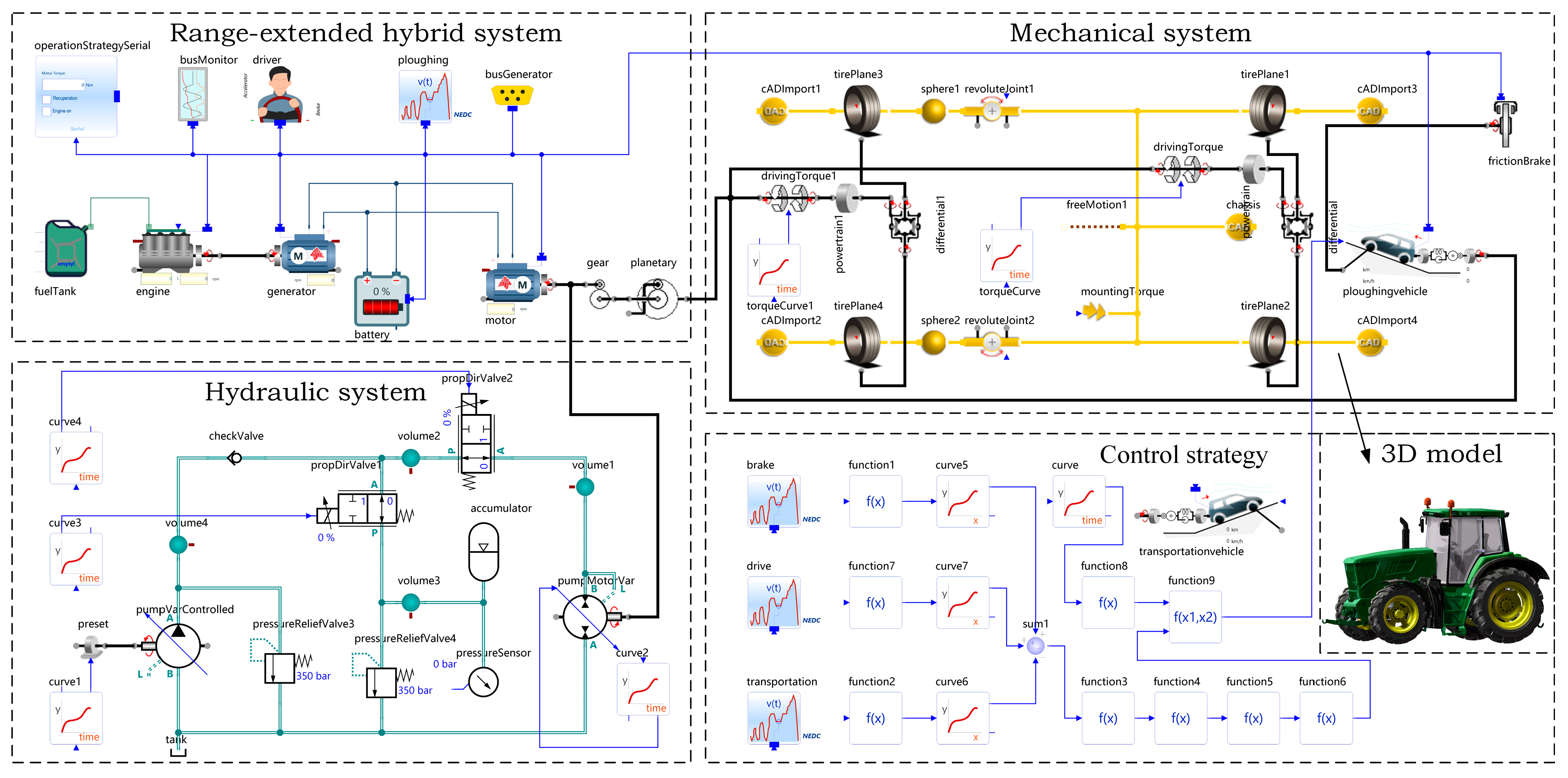
5.2. Multidisciplinary Co-Simulation Model

The process of simulating the operation of the hybrid tractor is illustrated in Figure 9. The target speed Vset is input into the driver model, which adjusts the pedal position based on feedback from the actual speed Vact. The required tractive force Ft and torque demand Treq are then calculated through the tractor’s longitudinal dynamics model. By comparing Treq with the predefined torque threshold Tset, the current driving mode is determined. Simultaneously, torque distribution during the driving and braking phases is optimized, enabling efficient energy recovery and utilization.
The multidisciplinary co-simulation model for the tractor’s traveling system was developed using SimulationX, as shown in Figure 10. The simulation model primarily comprises a range-extended hybrid system, hydraulic system, mechanical system, control strategy, and 3D model and can validate the effectiveness of the proposed control strategy and hybrid powertrain. A comparative analysis was conducted with a pure electric drive tractor in terms of their start–stop dynamics during both plowing and transport operations.

6. Simulation Analysis

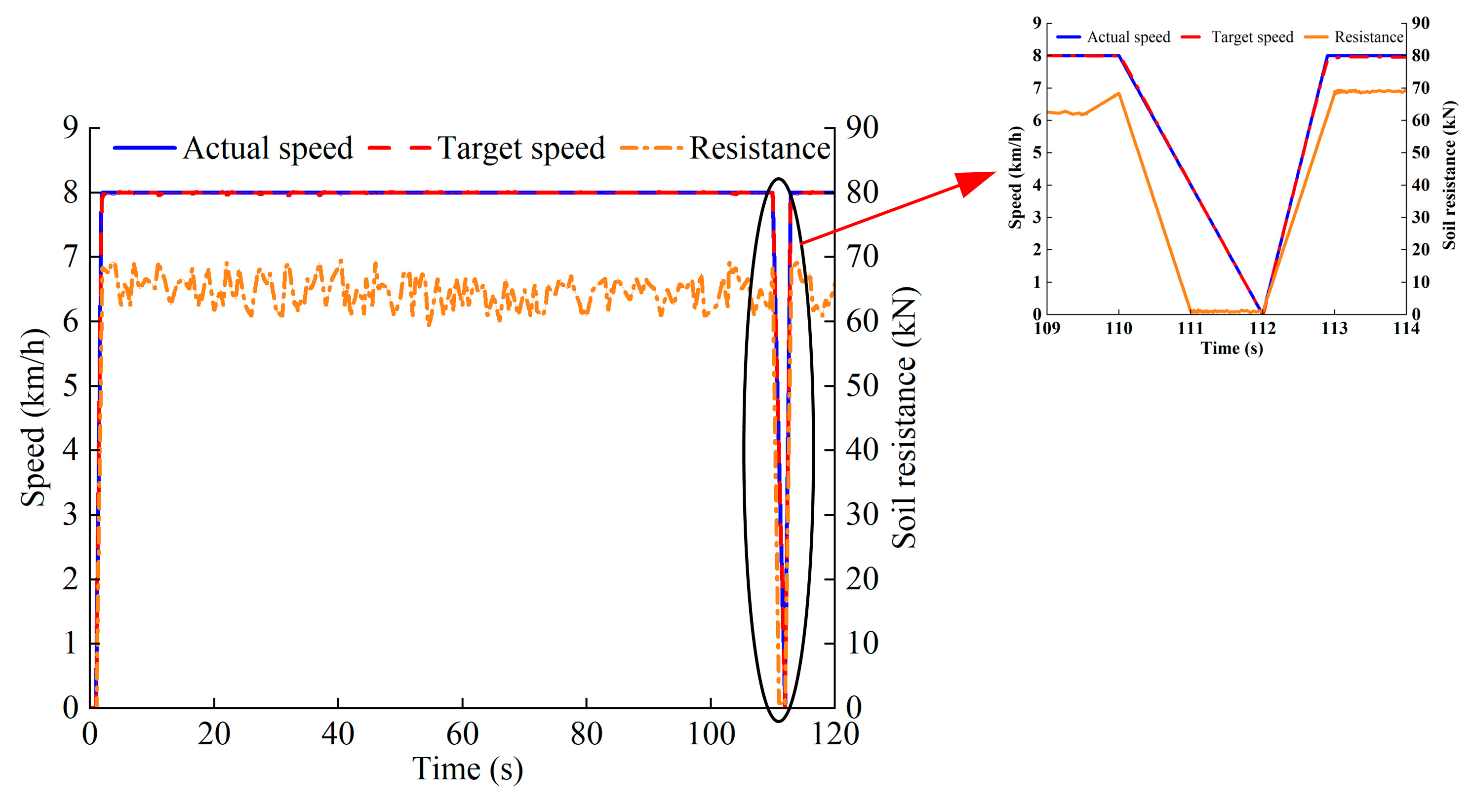
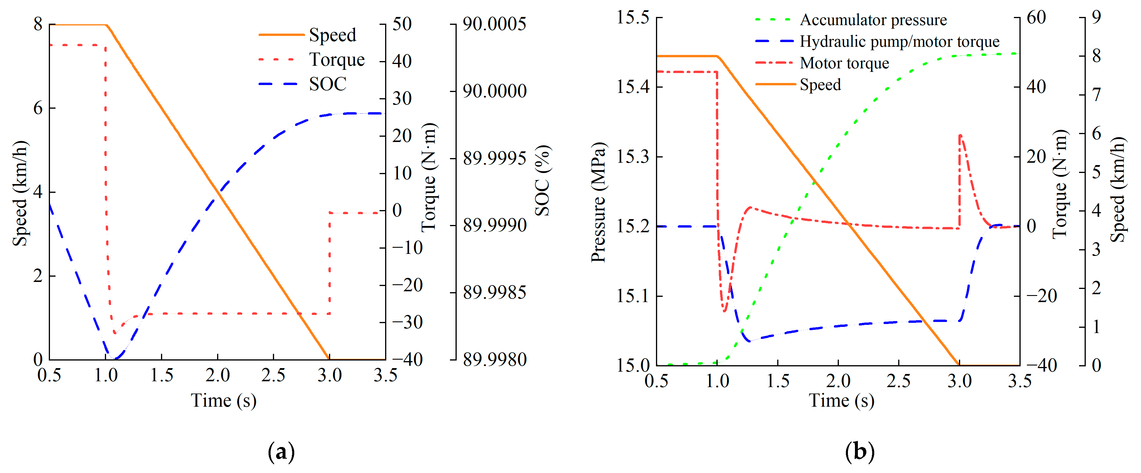
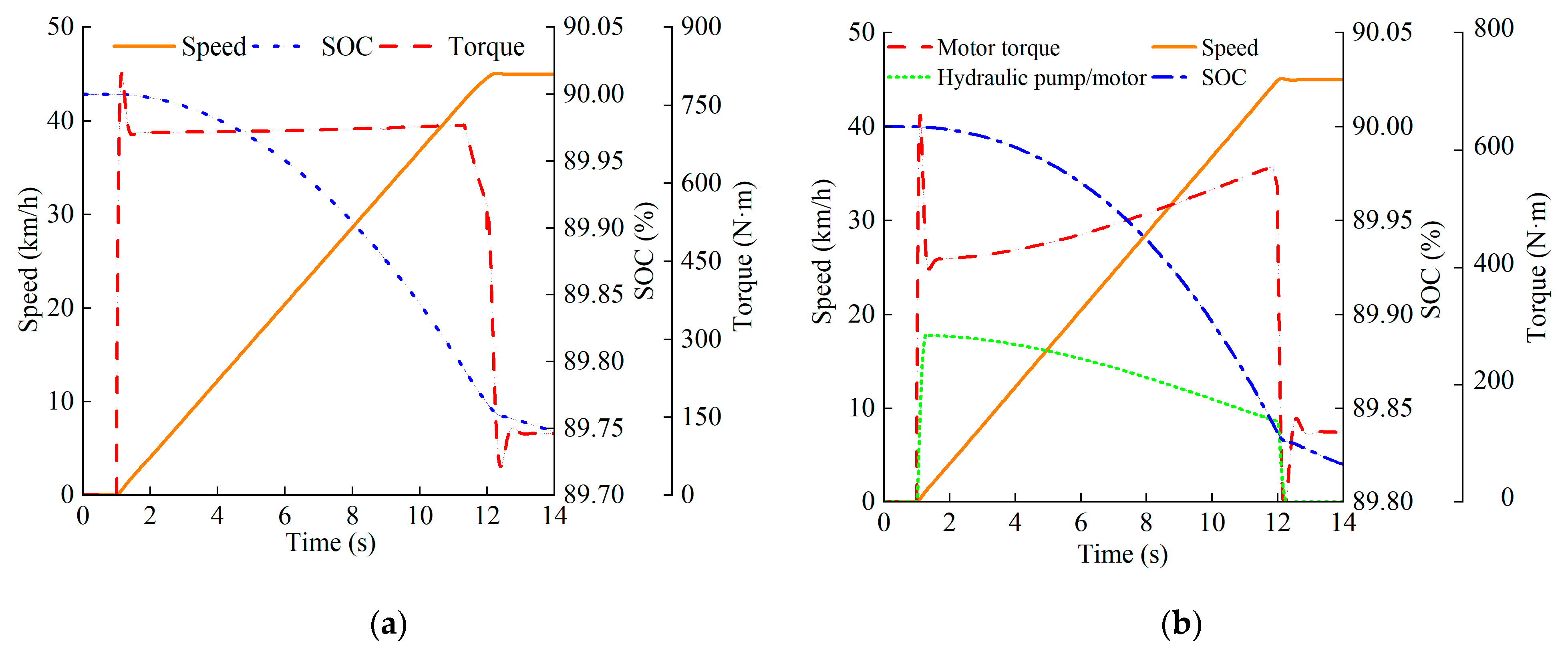
6.1. Plowing Operations

The variations in soil resistance and the target speed and actual speed of the tractor during plowing operations are shown in Figure 11. The maximum speed error is 0.05 km/h; this error prolongs the startup process by 0.2 s and increases energy consumption by 0.9%, with the deviation remaining within acceptable tolerance limits. From 0 s to 1 s, the tractor is in Parking Mode. Between 1 s and 2 s, it accelerates to 8 km/h, followed by constant-speed travel and headland turning, completing one operational cycle in a total duration of 110 s. A comparative analysis was then conducted between the pure electric drive and hydraulic–electric hybrid drive systems regarding their power performance and energy efficiency under startup and braking conditions.
The results of the pure electric drive startup simulation, as shown in Figure 12a, reveal that the tractor accelerates from 0 to 8 km/h between 1 s and 2.13 s, for a duration of 1.13 s. The motor torque increases to 705 N·m and then gradually decreases to 677 N·m until the acceleration phase concludes. The acceleration peaks at 2.3 m/s2 before declining to 2.08 m/s2. From 1.9 s to 3 s, the tractor maintains a constant speed of 8 km/h, with the motor torque rapidly dropping to 557 N·m after minor fluctuations.
The results of the hydraulic–electric hybrid drive simulation, as illustrated in Figure 12b, reveal that the tractor accelerates from 0 to 8 km/h between 1 s and 1.98 s, completing the process in 0.98 s through the collaborative drive of the motor and hydraulic pump/motor. Initially, the motor’s peak torque reaches 688 N·m. As the torque of the hydraulic pump/motor increases to a maximum of 164 N·m (it later decreases to 144 N·m), the motor torque correspondingly reduces to 557 N·m, achieving an 18.8% reduction in peak motor torque. After acceleration, the hydraulic pump/motor ceases its participation in the drive process. The maximum acceleration was reduced from 2.64 m/s2 to 2.39 m/s2. This design shortens the startup time by 0.15 s in plowing operations and improves the acceleration capability of the tractor by 23%, significantly enhancing operational efficiency.
The braking simulation with motor-only braking torque, as shown in Figure 13a, ensure that the braking process relies solely on the motor to provide braking torque. The tractor decelerates from 8 km/h over 2 s. At the initiation of braking, the motor delivers a braking torque of 32 N·m, which rapidly decreases to 27 N·m until braking concludes. Between 0.5 s and 1 s, the tractor maintains constant-speed travel, during which the battery’s SOC decreases. From 1 s to 3 s, the motor operates in power generation mode, raising the battery’s SOC from 89.998% to 89.999%, with 9.72 kJ of braking energy recovered. The braking energy recovery rate reaches 46.3%.
Hydraulic regenerative braking simulation results, as illustrated in Figure 13b, show that the tractor decelerates from 8 km/h to 0 between 1 s and 3 s. The hydraulic pump/motor operates in “pump mode”, providing an average braking torque of 28 N·m. The accumulator’s pressure increases from 15 MPa to 15.4 Mpa, converting braking energy into hydraulic energy. A total of 7.73 kJ is recovered through hydraulic regeneration. Simultaneously, the motor contributes a smaller braking torque, recovering an additional 2.37 kJ of energy. Their combined braking energy recovery rate reaches 48.3%.
An energy consumption comparison between the pure electric drive and hydraulic–electric hybrid drive tractors is shown in Figure 14; the tractor decelerates from 8 km/h to 0 between 1 s and 3 s and accelerates back to 8 km/h from 3 s to 4 s, simulating the start–stop cycles performed during field headland turning. Braking phase: The pure electric tractor relies on its battery to recover energy. The hydraulic–electric hybrid tractor recovers energy via the accumulator and reuses it during the restart phase. Startup phase: The pure electric drive motor reaches a peak power of 170 kW. The hydraulic–electric hybrid drive distributes power between the motor (108 kW) and hydraulic pump/motor (78 kW), reducing the motor’s peak power by 36.5%. After a complete headland turning cycle, the pure electric tractor consumes 299.5 kJ of energy and its battery energy consumption is 83.19 Wh. The hydraulic–electric hybrid tractor consumes 244.1 kJ of energy and its battery energy consumption is 67.81 Wh, reducing the energy consumed by 18.5%.

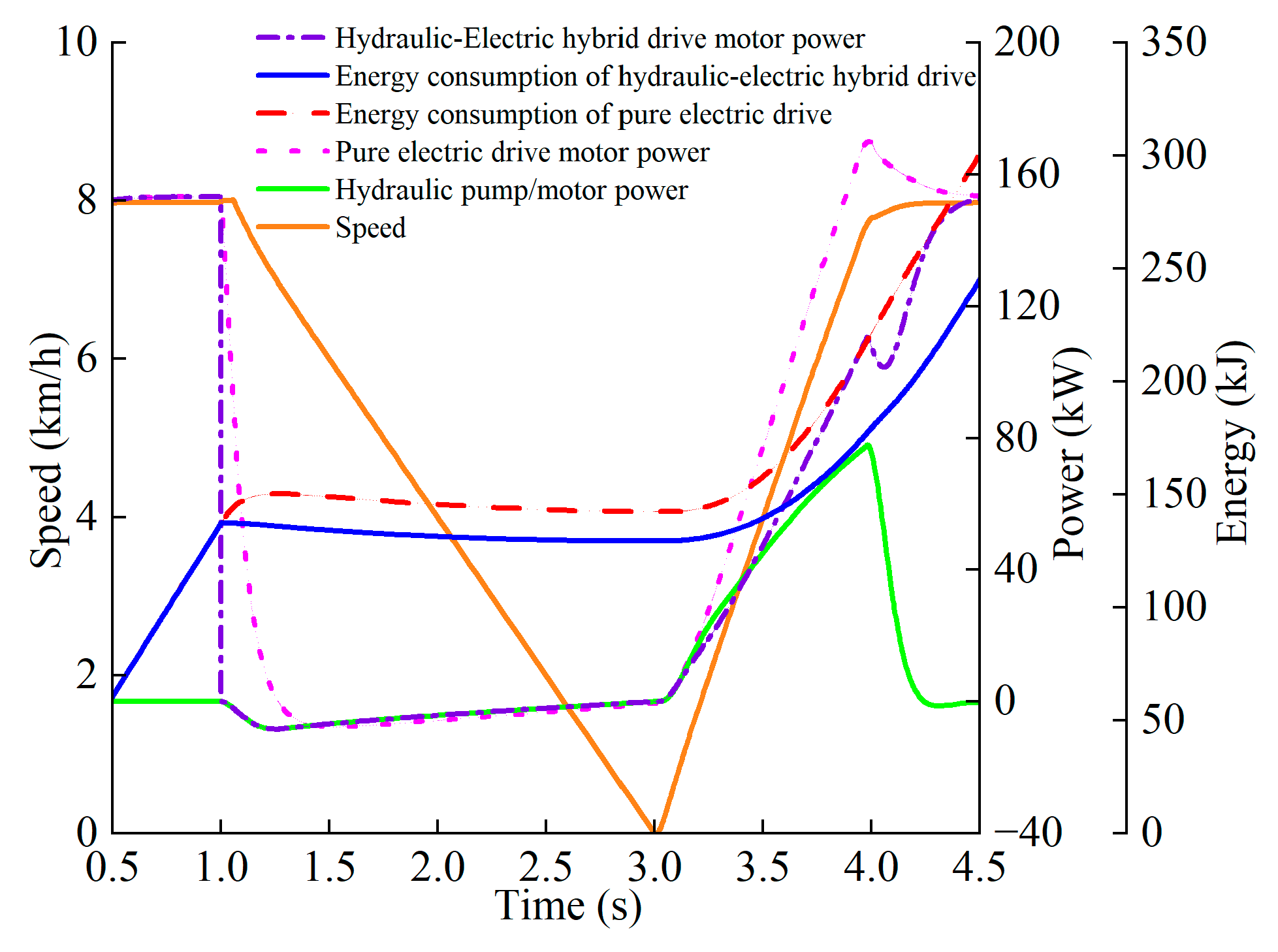
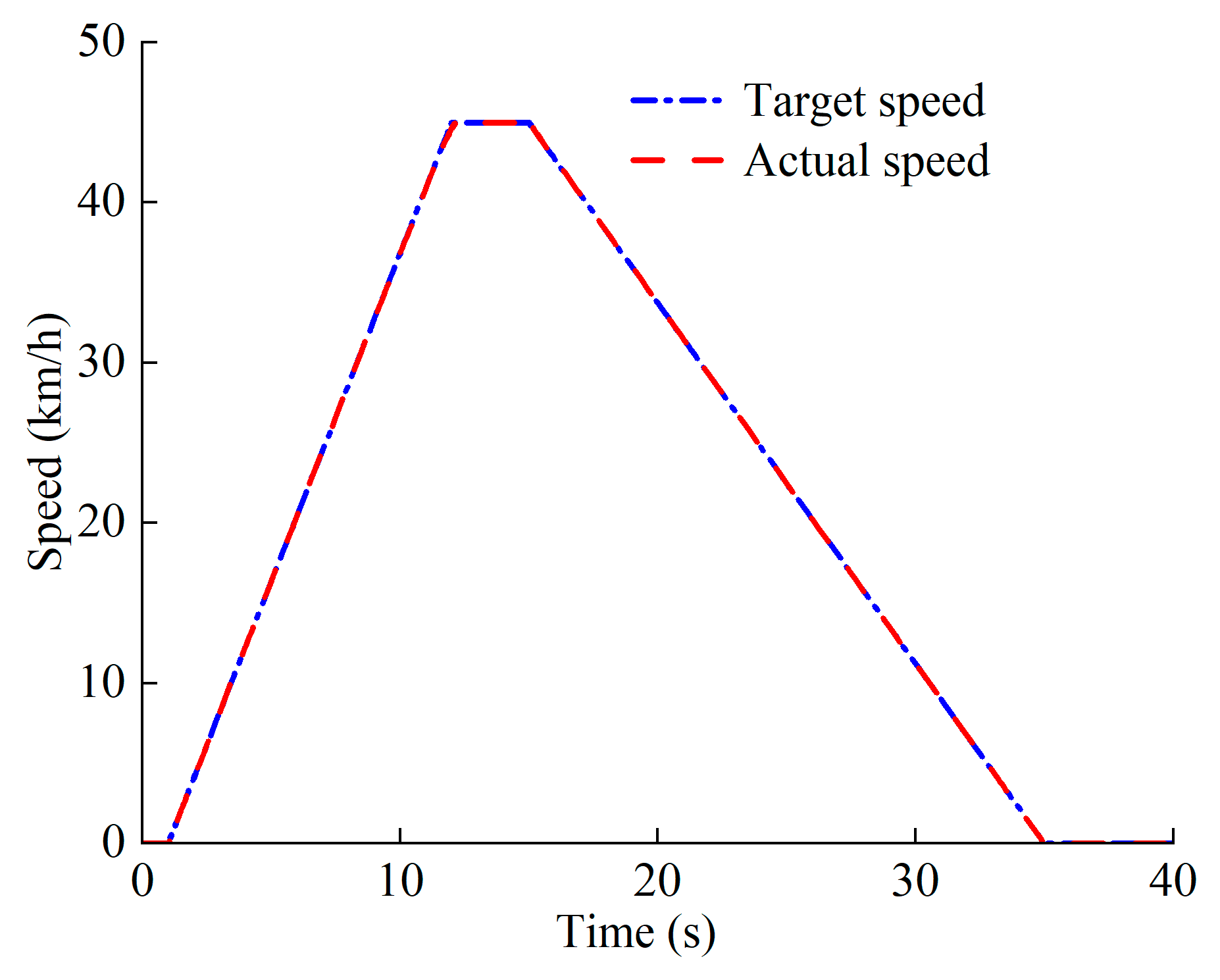
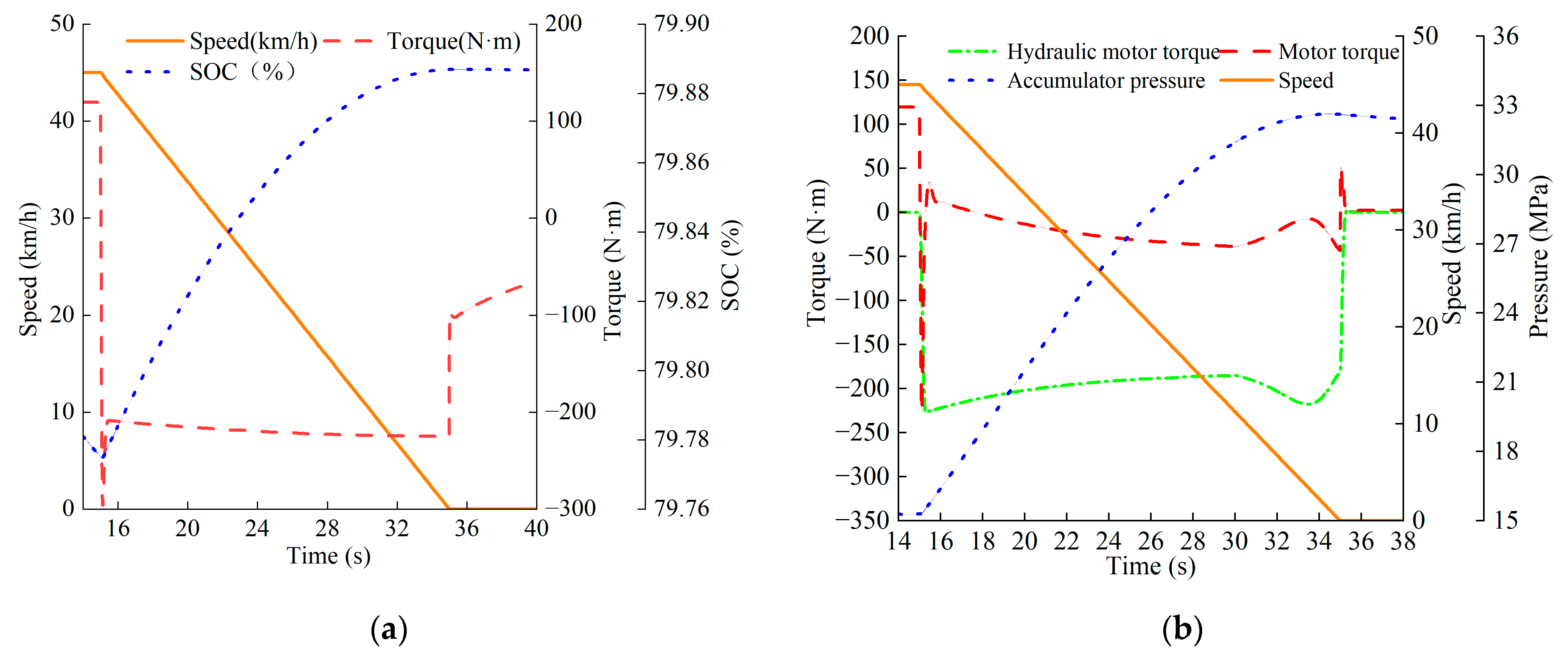
6.2. Transport Operations

The target speed and actual speed of the tractor during transport operations are shown in Figure 15. From 0 s to 1 s, the tractor remains stationary. Between 1 s and 12 s, it accelerates from a standstill to 45 km/h before maintaining a constant speed of 45 km/h from 12 s to 15 s and then decelerating from 45 km/h to 0 km/h between 15 s and 35 s. The results demonstrate a maximum speed error of 0.08 km/h during continuous operation for 1 h; the positional deviation of the tractor reaches approximately 80 m. Under transportation conditions, this deviation results in a 1.5% increase in total energy consumption while still accurately reflecting the tractor’s actual energy consumption characteristics, confirming that the simulation model accurately reflects real-world tractor behavior.
The pure electric drive simulation results are shown in Figure 16a; the tractor completes the 0–45 km/h acceleration process from 1 s to 12 s. At startup, the motor reaches a peak torque of 810 N·m, which subsequently decreases to 700 N·m to sustain acceleration. After acceleration, the tractor maintains a constant speed of 45 km/h from 12 s to 14 s, with the motor torque rapidly dropping to 119 N·m following transient oscillations. During the startup phase, the battery’s SOC decreases from 90% to 89.75%.
The hydraulic–electric hybrid drive simulation results are illustrated in Figure 16b; this tractor also achieves 0–45 km/h acceleration from 1 s to 12 s with a hydraulic pump/motor contribution of 137 N·m. The motor’s peak torque reaches 659 N·m, which is an 18.6% reduction compared to the pure electric drive tractor. From 1 s to 12 s, the motor’s torque increases from 397 N·m to 572 N·m, collaborating with the hydraulic pump/motor to complete the startup process, achieving a 35.7% reduction in peak motor torque. During startup, the battery’s SOC decreases from 90% to 89.83%.
The braking simulation with motor-only energy recovery is shown in Figure 17a; the braking process relies solely on motor reversal for energy recovery. Between 15 and 35 s, the tractor decelerates from 45 km/h to 0 after a period of constant-speed travel. The motor provides an average braking torque of 215 N·m, which gradually reduces to zero after the tractor comes to a complete stop. Throughout braking, the motor operates in power generation mode, increasing the battery’s SOC from 79.77% to 79.89% and recovering 588 kJ of braking energy, achieving a braking energy recovery rate of 61%.
The hydraulic regenerative braking simulation results are illustrated in Figure 17b; the tractor completes the braking process from 45 km/h to 0 between 15 s and 35 s. At the initiation of braking, the motor briefly generates a positive torque before dropping to zero, while the hydraulic pump/motor primarily recovers braking energy into the accumulator. The hydraulic pump/motor initially provides a braking torque of 324 N·m, which decreases as the accumulator pressure rises, yielding an average braking torque of 220 N·m. The accumulator pressure increases from 15 MPa to 32.2 Mpa, recovering 635 kJ of braking energy with a braking energy recovery rate of 66.4%.
In energy consumption comparison between the two systems shown in Figure 18, the tractor accelerates from 0 to 45 km/h between 1 s and 12 s. The motor power peaks at 183 kW for the pure electric drive, consuming 1066 kJ of energy. The battery’s energy consumption is 296.11 Wh. The motor and hydraulic pump/motor of the hydraulic–electric hybrid drive system deliver 144 kW and 42 kW, respectively, with the motor consuming 792 kJ of energy and a battery energy consumption of 220 Wh. From 12 s to 15 s, the tractor maintains a constant speed of 45 km/h, with both the motor and hydraulic pump/motor operating at stable power levels. Between 15 s and 35 s, the tractor decelerates from 45 km/h to 0. The hydraulic pump/motor operates in “pump mode”, while the motor switches to power generation mode, recovering braking energy. After a complete start–stop cycle, the hydraulic–electric hybrid drive system achieves a 25.7% reduction in energy used compared to the pure electric drive system.

7. Discussion

The hydraulic–electric hybrid drive system proposed in this study demonstrates significant advantages in reducing peak motor torque and improving energy utilization. Our simulation results reveal that under plowing conditions, the hybrid system reduces its peak motor torque by 18.8%, shortens its startup time by 0.15 s, and enhances its braking energy recovery efficiency to 48.3% through coordinated hydraulic pump/motor actuation. Under transportation conditions, its peak motor torque decreases by 35.7%, with its braking energy recovery efficiency further optimized to 66.4%. Its overall energy consumption is reduced by 18.5% (plowing) and 25.7% (transportation) compared to pure electric drive systems. These results validate the potential of hydraulic systems in compensating for transient high-torque demands and efficiently recovering braking energy, particularly in tractor applications that involve frequent start–stop cycles and high-inertia loads.
Unlike existing studies, this research innovatively integrates a hydraulic drive system into a range-extended hybrid architecture, achieving power coupling via a planetary gear mechanism. This approach overcomes the reliance on motor power density inherent in traditional electric drive systems. The hierarchical braking energy recovery mechanism balances energy recovery efficiency and braking safety through prioritized allocation strategies, offering greater engineering practicality than single-motor recovery solutions. However, limitations remain: the simulation model does not account for hydraulic components’ dynamic response delays or real-world soil parameter variations in the field, which may affect its accuracy. Additionally, accumulator capacity and pressure limitations may constrain the sustained performance of tractors under prolonged high-load operations.
Future work should validate this system’s robustness in real-world plowing and transportation tasks through field trials and explore advanced control algorithms (e.g., model predictive control, MPC) to enhance its dynamic adaptability during mode transitions. Concurrently, cost–benefit analyses of its key components (e.g., high-density batteries and hydraulic accumulators) will aid in assessing the technology’s commercial viability for small-to-medium farms. Extending this hybrid architecture to other high-power agricultural machinery (e.g., combine harvesters) could accelerate the greening and intelligentization of agricultural equipment, contributing to global goals of agricultural carbon neutrality.

Author Contributions

Conceptualization, H.W. and L.Q.; methodology, H.W.; software, H.W.; validation, H.W., Z.P. and L.Q.; formal analysis, H.W.; investigation, Y.H.; resources, S.X.; data curation, Y.H.; writing—original draft preparation, H.W.; writing—review and editing, H.W. and L.Q.; visualization, H.W.; supervision, L.Q. and S.X.; project administration, L.Q.; funding acquisition, Y.H. and L.Q. All authors have read and agreed to the published version of the manuscript.

Funding

This research was funded by the National Key Research and Development Program of China, grant number 2022YFB3403005.

Data Availability Statement

The data are available within the article, and any additional inquiries regarding the findings should be addressed to the corresponding author.

Acknowledgments

The authors acknowledge the technical support and experimental materials provided by the Institute of Mechanical and Electrical Engineering, School of Mechanical Engineering, Taiyuan University of Technology.

Conflicts of Interest

The authors declare no conflicts of interest.

References

  1. Tian, Y.; Zhao, Y.; Wang, Z.; Zhang, Y.; Miao, Y.; Zhang, L.; Wen, G.; Zhang, N. Non-dominated sorting artificial rabbit multi-objective sizing optimization for a conceptual powertrain of a 6 × 4 battery electric tractor truck. Energy 2024, 304, 132009. [Google Scholar] [CrossRef]
  2. Ali, D.; de Castro, R.; Ehsani, R.; Vougioukas, S.; Wei, P. Unlocking the potential of electric and hybrid tractors via sensitivity and techno-economic analysis. Appl. Energy 2025, 377, 124545. [Google Scholar] [CrossRef]
  3. Lei, S.; Li, Y.; Liu, M.; Li, W.; Zhao, T.; Hou, S.; Xu, L. Hierarchical Energy Management and Energy Saving Potential Analysis for Fuel Cell Hybrid Electric Tractors. Energies 2025, 18, 247. [Google Scholar] [CrossRef]
  4. Liu, H.; Shen, C.; HU, L.; Chang, C.; Cao, G. Research progress and development trend of electric agricultural equipment. Trans. Chin. Soc. Agric. Eng. 2024, 40, 39–51. [Google Scholar]
  5. Sun, H.; Wang, J.; Wu, J. Current Status and Trends in Energy Management Strategies for Hybrid Electric Vehicles. Automob. Appl. Technol. 2024, 24, 118–121. [Google Scholar]
  6. Pan, M.; Cao, S.; Zhang, Z.; Ye, N.; Qin, H.; Li, L.; Guan, W. Recent progress on energy management strategies for hybrid electric vehicles. J. Energy Storage 2025, 116, 115936. [Google Scholar] [CrossRef]
  7. Zhu, Z.; Zeng, L.; Chen, L.; Zou, R.; Cai, Y. Fuzzy Adaptive Energy Management Strategy for a Hybrid Agricultural Tractor Equipped with HMCVT. Agricultural 2022, 12, 1986. [Google Scholar] [CrossRef]
  8. He, X.; Yu, Q.; Jiang, Z.; Tan, Y.; Chen, Y.; Xie, B.; Wen, C. Dual-layer adaptive power management strategy for E-tractor incorporating operating information and deep reinforcement learning. Energy 2025, 319, 134942. [Google Scholar] [CrossRef]
  9. Francesco, M.; Aurelio, S. Analysis of a Parallel Hybrid Electric Tractor for Agricultural Applications. Energies 2020, 13, 3055. [Google Scholar] [CrossRef]
  10. Zhang, J.; Feng, G.; Liu, M.; Yan, X.; Xu, L.; Shang, C. Research on Global Optimal Energy Management Strategy of Agricultural Hybrid Tractor Equipped with CVT. World Electr. Vehic. J. 2023, 14, 127. [Google Scholar] [CrossRef]
  11. Wang, S.; Wu, X.; Zhao, X.; Wang, S.; Xie, B.; Song, Z.; Wang, D. Co-optimization energy management strategy for a novel dual-motor drive system of electric tractor considering efficiency and stability. Energy 2023, 281, 128074. [Google Scholar] [CrossRef]
  12. Li, Z.; Xiao, P.; Pan, J.; Pei, W.; Lv, A. Energy management strategy for methanol hybrid commercial vehicles based on improved dung beetle algorithm optimization. PLoS ONE 2025, 20, e0313303. [Google Scholar] [CrossRef]
  13. Li, L.; Gao, Z.; Nie, J. Load-adaptive Energy Management Strategy for Electric Tractor Based on Hybrid Power Source. Trans. Chin. Soc. Agric. Mach. 2024, 55, 459–469. [Google Scholar]
  14. Zhao, Y.; Xu, L.; Zhao, C.; Xu, H.; Yan, X. Research on Energy Management Strategy for Hybrid Tractors Based on DP-MPC. Energies 2024, 17, 3924. [Google Scholar] [CrossRef]
  15. Zhao, S.; Gao, Z.; Li, X.; Li, Y.; Xu, Y. Research on Energy Management Stractegy of Fuel Cell Tractor Hybrid Power System. World Electr. Vehic. J. 2024, 15, 61. [Google Scholar] [CrossRef]
  16. Zhao, X.; Zhang, G.; Wang, J.; Xue, Z.; Liu, M.; Liu, Y. Study and Verification of a Fuzzy-Following Energy Management Strategy for Hybrid Tractors. World Electr. Vehic. J. 2024, 16, 18. [Google Scholar] [CrossRef]
  17. Ahtisham, U.; Ali, N. Review of intelligent energy management techniques for hybrid electric vehicles. J. Energy Storage 2024, 92, 112132. [Google Scholar]
  18. Manuel, A.P.E.; Joaquim, M.F.; Joaquim, A.L.; Luigi, A.; Massimiliano, R. Optimal design of aseries hybrid powertrain for an agricultural tractor. Energy Convers. Manag. 2024, 24, 100789. [Google Scholar]
  19. Li, T.; Xie, B.; Li, Z.; Li, J. Design and Optimization of a Dual-Input Coupling Powertrain System: A Case Study for Electric Tractors. Appl. Sci. 2020, 10, 1608. [Google Scholar] [CrossRef]
  20. Park, Y.J.; Kim, J.G.; Lee, G.H. Characteristic Analysis of Planetary Gear Set of Hydromechanical Transmission System of Agricultural Tractors. J. Biosyst. Eng. 2016, 41, 145–152. [Google Scholar] [CrossRef]
  21. Claudio, R.; Davide, P.; Carlo, F.; Marco, B.; Riccardo, M. A Hybrid–Electric Driveline for Agricultural Tractors Based on an e-CVT Power-Split Transmission. Energies 2021, 14, 6912. [Google Scholar] [CrossRef]
  22. Quan, L.; Yan, Z.; Zhang, S.; Yang, Y.; Ge, L.; Li, Z. New Progress in Energy-efficient Electrical Drive and Hydraulic Transmission Technologies for Non-road Mobile Equipment. J. Mech. Eng. 2023, 59, 385–400. [Google Scholar]
  23. Cui, J.; Quan, L.; Liu, Z.; Ge, L.; Huang, W. Characteristics and Energy Efficiency Analysis of Electro-hydraulic Hybrid Drive Large Inertia Swing System. Trans. Chin. Soc. Agric. Manchinery 2023, 54, 450–458. [Google Scholar]
  24. Li, Z.; Wang, C.; Quan, L.; Hao, Y.; Ge, L.; Xia, L. Study on energy efficiency characteristics of the heavy-duty manipulator driven by electro-hydraulic hybrid active-passive system. Automat. Constr. 2021, 125, 103646. [Google Scholar] [CrossRef]
  25. Lin, L.; Zhang, T.; Lu, L.; Zhang, H.; Yang, J.; Zhang, Z. An energy active regulation management strategy based on driving mode recognition for electro-hydraulic hybrid vehicles. Energy 2023, 285, 129548. [Google Scholar]
  26. Mu, H.; Cheng, H.; Tang, X.; Ding, Q.; Ma, W. A hybrid distributed-centralized load sensing system for efficiency improvement of electrified construction machinery. Energy 2025, 314, 134123. [Google Scholar] [CrossRef]
  27. ISO 15550:2016; Internal Combustion Engines—Determination and Method for the Measurement of Engine Power—General Requirements. ISO: Geneva, Switzerland, 2016.
  28. IEC 62660-1:2018; Secondary Lithium-Ion Cells for the Propulsion of Electric Road Vehicles—Part 1: Performance Testing. IEC: Geneva, Switzerland, 2018.
  29. ISO 8854:2012; Road Vehicles—Alternators with Regulators—Test Methods and General Requirements. ISO: Geneva, Switzerland, 2012.
  30. ISO 8426-2:2024; Hydraulic Fluid Power—Determination of Derived Displacement of Positive Displacement Pumps and Motors—Part 2: Zero-Pressure Intercept Method. ISO: London, UK, 2024.
Figure 1. Hybrid tractor system configuration.
Energies 18 02075 g001
Figure 2. Hydraulic–electric hybrid drive system. 1—methanol engine; 2—hydraulic pump; 3—relief valve; 4—hydraulic pump/motor; 5—check valve; 6—on–off valve; 7—accumulator; 8—transmission; 9—drive motor; 10—charger; 11—planetary gear.
Energies 18 02075 g002
Figure 3. (a) Effective fuel consumption rate of engine; (b) efficiency of motor in generation mode.
Energies 18 02075 g003
Figure 4. Curves of battery charge and discharge characteristics.
Energies 18 02075 g004
Figure 5. (a) Motor power map; (b) motor efficiency map.
Energies 18 02075 g005
Figure 6. Schematic diagram of tractor stress.
Energies 18 02075 g006
Figure 7. Control strategy for working mode selection.
Energies 18 02075 g007
Figure 8. Tractor hydraulic–electric hybrid drive and regenerative braking control strategy.
Energies 18 02075 g008
Figure 9. Process of simulating hybrid tractor.
Energies 18 02075 g009
Figure 10. Multidisciplinary co-simulation model of the hydraulic–electric hybrid drive tractor’s traveling system.
Energies 18 02075 g010
Figure 11. Tractor speed in plowing operations.
Energies 18 02075 g011
Figure 12. (a) Tractor with pure electric drive; (b) tractor with hydraulic–electric hybrid drive.
Energies 18 02075 g012
Figure 13. (a) Tractor with pure electric braking; (b) tractor with hydraulic regenerative braking.
Energies 18 02075 g013
Figure 14. Comparative analysis of energy consumption characteristics of tractor components during plowing operations.
Energies 18 02075 g014
Figure 15. Tractor speed during transport operations.
Energies 18 02075 g015
Figure 16. (a) Tractor with pure electric drive; (b) tractor with hydraulic–electric hybrid drive.
Energies 18 02075 g016
Figure 17. (a) Tractor with pure electric braking; (b) tractor with hydraulic regenerative braking.
Energies 18 02075 g017
Figure 18. Comparative analysis of energy consumption characteristics of tractor components during transport operations.
Energies 18 02075 g018
Table 1. Parameters of main components of hybrid tractor.
ComponentsParametersValueStandardsResponse Time
TractorMass8500 kg--
Drive wheel radius0.725 m
Range extenderEngine rated power200 kW (≤±5%)ISO 15550 [27]3 s
Engine rated speed2500 r/min (≤±3%)
Minimum fuel consumption rate470 g/(kWh) (≤±0.8%)
BatteryRated capacity150 kWh (≤±2%)IEC 62660-1 [28]50 ms
Rated voltage380 V (≤±0.02%)
SOC20–80% (≤±3%)
Drive motorRated power165 kW (≤±3%)ISO 8854:2012 [29]7 ms
Rated speed2800 r/min (≤±3%)
Rated torque560 N·m (≤±0.3%)
Hydraulic pump/motorRated power220 kW (≤±5%)ISO 8426 [30]25 ms
Rated torque401 N·m (≤±0.3%)
Maximum displacement63 mL/r (≤±0.5%)
Table 2. Working modes of hybrid tractor.
Working ModeRange ExtenderDrive MotorHydraulic Pump/Motor
ParkingShut downShut downShut down
Hydraulic–Electric Hybrid DriveShut downStart (motor)Start (motor)
Braking Energy RecoveryShut downStart (generator)Start (pump)
Pure Electric DriveShut downStart (motor)Shut down
Range-Extended ModeStartStart (motor)Shut down
Disclaimer/Publisher’s Note: The statements, opinions and data contained in all publications are solely those of the individual author(s) and contributor(s) and not of MDPI and/or the editor(s). MDPI and/or the editor(s) disclaim responsibility for any injury to people or property resulting from any ideas, methods, instructions or products referred to in the content.

