Article

Enhancing Performance of PEM Fuel Cell Powering SRM System Using Metaheuristic Optimization

1
Energy and Sustainable Engineering Department, College of Engineering, A’Sharqiyah University, P.O. Box 42, Ibra 400, Oman
2
Electrical Engineering and Computer Science Department, College of Engineering, A’Sharqiyah University, P.O. Box 42, Ibra 400, Oman
3
Electrical Power and Machines Department, Faculty of Engineering, Zagazig University, Zagazig 44519, Egypt
*
Author to whom correspondence should be addressed.
Energies 2025, 18(8), 2004; https://doi.org/10.3390/en18082004
Submission received: 21 March 2025 / Revised: 7 April 2025 / Accepted: 11 April 2025 / Published: 14 April 2025
(This article belongs to the Special Issue Applications of Fuel Cell Systems)

Abstract

:
This paper introduces an effective method to improve the performance of a proton exchange membrane fuel cell (PEMFC) system powering a switched reluctance motor (SRM). Problems arise in this system due to the inherent torque and current ripples of the SRM, which result from its saliency and nonlinear magnetic characteristics. Another cause for these ripples is the unsmoothed DC voltage applied to the SRM caused by the switching operations of the DC-DC converter. These ripples are reflected in the PEMFC, leading to more losses and a reduced lifespan. Key parameters that can help mitigate torque and current ripples include the appropriate turn-on and turn-off angles of the SRM phases, as well as the DC-link voltage controller gains. This paper investigates three objectives to compare their effects on the PEMFC system: the SRM torque ripple factor, the DC-link voltage ripple factor, and the PEMFC current ripple factor. These objectives are optimized individually using the single-objective particle swarm and stochastic fractal search algorithms. Additionally, the multi-objective Lichtenberg and multi-objective Dragonfly algorithms are applied to optimize the three objectives concurrently. The optimal decision parameters are obtained from the Pareto front solution using the technique of the order of preference by similarity to the ideal solution method. The final results demonstrate that significant enhancement in the PEMFC current ripples and DC-link voltage ripples can be achieved by appropriately selecting the decision parameters using any proposed objective.

1. Introduction

The global transition toward cleaner and more sustainable energy sources drives the increasing adoption of hydrogen energy as a storage medium. Consequently, the hydrogen fuel cell vehicle industry is expanding as part of the shift toward zero-emission transportation. Various types of electric motors can be used to drive these vehicles [1], with switched reluctance motors (SRMs) offering several advantages for electric vehicle applications. These advantages include a high torque-to-ampere ratio, a high starting torque, rapid acceleration, high-speed operation, and rugged construction [2], attributed to their rotor design, which has no windings. However, SRMs suffer from torque and current ripples due to the stator and rotor circuits’ saliency and nonlinear magnetic characteristics. When an SRM is powered by fuel cells, the current exhibits large ripples, further amplified by power electronic converters’ switching operations to regulate the fuel cell output voltage. These ripples negatively impact the lifespan and efficiency of the fuel cell.
The impact of current ripples on the performance of a proton exchange membrane fuel cell (PEMFC) stack was experimentally investigated in [3], where a boost DC converter was used to regulate the stack’s output DC voltage. The study revealed that converter switching introduced current ripples, leading to a reduction in output voltage, a shift in the operating point, and decreased efficiency. In [4], the effects of ripple currents on PEMFC performance were discussed, highlighting that specific waveforms and frequencies may contribute to degradation, an increase in high-frequency resistance, or even mass transport limitations. Based on impedance measurements, the diagnosis of cathode flooding and membrane drying due to current ripples was introduced in [5]. The study concluded that low-frequency current ripples accelerate PEMFC degradation. The research in [6] demonstrated that current ripples significantly contribute to additional losses in fuel cell-powered heavy-duty trucks, negatively impacting efficiency and operational costs. In [7], a Horizon 300 W PEMFC stack was examined to determine the effects of current ripples on lifetime, fuel consumption, utilization, temperature elevation, and output power. The study concluded that current ripples reduced lifetime, efficiency, and power while elevating PEMFC fuel consumption, temperature, and utilization.
Numerous articles in the literature focus on reducing the ripples produced by power electronic converters that regulate the PEMFC output voltage. In [8], a modified buck-boost converter was proposed to extend the lifespan of the PEMFC stack. The modified converter topology significantly reduced input current and voltage ripples. This design substitutes the large inductor of the double-switch buck-boost converter with two smaller, interleaved inductors. In [9], three current ripple reduction approaches were presented for an uninterruptible power supply (UPS) system that integrates a hybrid PEMFC and a supercapacitor (SC) with a high-efficiency push–pull DC/DC converter. The study analyzed recent ripple generation in the UPS hybrid system using SCs, an LC filter, and an active clamp circuit. Experimental verification demonstrated that the active compensation method outperformed passive compensation methods in minimizing input current ripples while offering cost-effectiveness and compactness. In [10], a parallel inductor multilevel current source inverter was integrated with a boost converter to reduce the current ripple drawn from the PEMFC.
It is highlighted in [11,12,13] that the advancement of SRMs is limited by challenges such as high torque ripple, vibration, and acoustic noise. There are two main approaches to mitigating torque ripples. The first focuses on improving the motor’s magnetic design, while the second employs advanced control techniques. Designers can reduce torque pulsations by modifying the stator and rotor poles structures, although this may come at the cost of specific motor performance parameters [14]. Several optimal design geometries have been proposed to enhance torque ripple performance, including segmented stators, double stators [15], C-core SRMs [16], segmented rotors [17], and rotor modifications incorporating flux barriers [18].
Additionally, extensive research has focused on optimizing control parameters such as current levels, supply voltage, and turn-on and turn-off angles through various control methods. Studies [19,20,21] have indicated that the relationship between motor torque and phase current primarily influences torque ripple in SRMs. To address this behavior, direct torque control (DTC) and indirect torque control techniques have been employed to regulate motor torque and current effectively. In [22], an energy control strategy based on the DTC approach was introduced to minimize both DC-link voltage ripple and torque ripple by maintaining constant instantaneous torque and stored field energy. However, few studies have simultaneously addressed both SRM torque ripple and source current ripple. Du et al. [23] proposed a novel current profile technique to mitigate both ripples, though it is limited to SRMs with a sinusoidal inductance profile. In [24], a model predictive control method was developed to suppress both torque and source current ripples by estimating rotor position, current, voltage, and flux-linkage for predictive control. In [25], a technique was presented that shapes motor phase currents to reduce DC-link current ripples across a wide speed range.
Artificial neural networks (ANNs) and fuzzy logic-based methods can learn from collected data and adapt control parameters to real-time data, making them highly flexible to varying conditions. Additionally, recent metaheuristic algorithms have proven effective in optimizing motor control parameters. Field reconstruction and non-derivative optimization methods have been applied to shape the current profile for reducing torque ripples [26]. In [27], a modified hybrid Whale optimization algorithm was employed for optimal speed control and torque ripple reduction in an 8/6 SRM, where the motor commutation angles along with the gains of a PI speed controller were optimized to enhance speed control and minimize ripple. In [28], a fuzzy indirect instantaneous torque controller was implemented to shape the instantaneous current based on torque error, effectively reducing torque ripples. The Water Cycle Algorithm was employed in [29] to optimize the gains of the PI speed controller and the commutation angles of an SRM, ensuring an improved speed response, minimal torque ripple, and a high torque-per-ampere ratio. Additionally, an ANN-based adaptive controller was designed to adjust the PI speed controller gains and commutation angles automatically.
This paper proposes a recent metaheuristic algorithm, the multi-objective Lichtenberg algorithm (MOLA) [30], to minimize the ripples in a PEMFC-feeding SRM system. Pereira et al. [31] recently introduced the Lichtenberg algorithm (LA) in its mono-objective form. This algorithm is inspired by lightning storms and Lichtenberg figures (LFs). The algorithm has been effectively applied to various applications, such as crack detection in composite materials [32], damage identification [33], and the optimal design of carbon polymers [34]. LFs are formed in the search space, where points within these figures serve as candidates for evaluating the objective function of the problem.
In stand-alone fuel cell systems, batteries and supercapacitors are crucial in enabling efficient energy storage and delivering surges of current that far exceed the current supplied by fuel cells. They also help regulate the output voltage of fuel cells, ensuring that the loads receive the required voltage levels. SCs are particularly recommended as auxiliary energy sources in fuel cell systems due to their fast response to dynamic system changes [35,36]. In [37,38], a hybrid power source combining a fuel cell, battery, and supercapacitor is proposed for electric vehicles, offering enhanced performance during high-speed operation and acceleration.
This article aims to identify the most effective objective for minimizing ripples in a PEMFC system. To achieve this, three objectives are optimized both individually and concurrently: the SRM torque ripple factor, the DC-link voltage ripple factor, and the PEMFC current ripple factor. In addition to the turn-on and turn-off angles of SRM phases, which are well-known parameters affecting torque ripples, this article also considers the gains of the DC-link PI voltage controller to smooth the SRM voltage, thereby contributing significantly to ripple reduction.
The key contributions of this paper are summarized as follows:
  • Three objectives are evaluated to mitigate ripples in the PEMFC system, identifying the one with the most significant impact.
  • These objectives are minimized both individually and concurrently under operating conditions with varying load torques and SRM speeds.
  • The system’s performance is assessed, including a detailed analysis of its effects on PEMFC current and voltage ripples.

2. System Architecture and Dynamic Modeling

The investigated system consists of a 6/4 switched reluctance motor (SRM) powered by a 6 kW proton exchange membrane fuel cell (PEMFC) stack through a boost converter (BC). A proportional-integral (PI) controller regulates the duty cycle of the BC’s integrated gate bipolar transistor (IGBT) switch to maintain a constant DC-link voltage of 240 V. To support transient operations, a 29 F supercapacitor (SC), and 14 Ah battery banks are connected to the DC link via bidirectional DC-DC converters. The PEMFC-SC-battery hybrid system powers the SRM through an H-bridge converter. The SRM speed is controlled using a dual-speed controller, which consists of an inner hysteresis current controller and an outer PI speed controller. Figure 1 illustrates the system’s schematic block diagram [39].

2.1. PEMFC

The electrochemical reaction in the PEMFC converts hydrogen chemical energy into electrical energy. The precise modeling of the PEMFC is critical to predict its behavior under different operating conditions and optimize its performance. In [36], the PEMFC model comprises a controlled voltage source with a constant series resistance. The stack’s total voltage ( V f c s ) is expressed by Equation (1):
V f c s = k v E n e r N A l n i f c s i o . 1 s T d / 3 + 1 i f c R
where E n e r is nernest voltage (V), k v is the voltage constant in the nominal operating condition, N is the cell number, A is the Tafel slope (V), i o is the exchange current (A), T d is the response time (at 95% of the final value) (s), R is the internal resistance (Ω), and i f c s is the fuel cell current (A).
The Nernst voltage is the cell’s maximum potential without load and is computed using Equation (2).
E n e r = 1.229 0.85 × 10 3 T 298 + 4.3085 × 10 5 T · ln P H 2 P O 2 1 2
P H 2 = 1 U f H 2 · x % · P f u e l
P O 2 = 1 U f O 2 · y % · P a i r
U f H 2 = 60000 R T i f c z F P f u e l · V f u e l · x %
U f O 2 = 60000 R T i f c 2 z F P a i r · V a i r · y %
where T is cell temperature (K), P H 2 is the partial pressure of hydrogen (bar), and P O 2 is the partial pressure of oxygen (bar), U f H 2 is the utilization of hydrogen, U f O 2 is the utilization of oxygen, P f u e l is absolute supply pressure of fuel (atm), P a i r is the absolute supply pressure of air (atm), x is the percentage of hydrogen in the fuel (%), y is the percentage of oxygen in the oxidant (%), V f u e l is the fuel flow rate (L/min), V a i r is the air flow rate (L/min), R is equal to 8.3145 J/(mol K), F is equal to 96,485 A s/mol, and z is number of moving electrons.

2.2. Supercapacitors

Supercapacitors are energy storage devices that allow fast charge and discharge cycles. A rapid response and a long lifecycle characterize them. In MATLAB (R2024b)/Simulink, the supercapacitor model consists of a controlled voltage source in series with internal resistance with the following assumptions: constant internal resistance during charging and discharging cycles, the temperature effect on electrolyte material being ignored, the aging effect being ignored, and continuous current through the supercapacitor [39,40]. The output voltage (Vsc) is expressed by Equation (7).
V s c = N s Q T d N p N e ε ε o A i + 2 N e N s R T F s i n h 1 Q T N p N e 2 A i 8 R T ε ε o C i s c R s c
Q T = i s c   d t
where N s is the number of series supercapacitors, N p is the number of parallel supercapacitors, N e is the number of layers of electrodes, Q T is the electric charge (C), d is the molecular constant, ε o is the permittivity of free space, ε is the permittivity of the material, A i is area (m2), T is the temperature (K), R is the ideal gas constant, F is the Faraday constant, C is the molar concentration (mol/m3), i s c is supercapacitor current (A), and R s c is total resistance (Ω).

2.3. Battery

Battery systems are crucial in modern energy storage, particularly for applications such as grid energy storage, electric vehicles (EVs), and renewable energy systems. Batteries can be classified based on their chemistry, structure, and functionality. Lithium-ion batteries are among the most widely used due to many merits, such as long cycle life, high energy density, and relatively high efficiency. In MATLAB/Simulink, the lithium-ion battery dynamic model is represented by a controlled voltage source in series with a resistance R representing the internal losses. The effect of both temperature and aging on model variables is considered. The battery output volage (Vbat) during discharge and charging is given by Equations (9)–(12) [41,42,43,44,45]:
Discharge   model   ( i > 0 ) :                                                                                                                                                                                                                         V b a t = f 1 i t ,   i , i i R
f 1 i t ,   i , i = E o K · i Q Q i t K · i t Q Q i t + A · e B · i t
Charge   model   ( i < 0 ) :                                                                                                                                                                                                                         V b a t = f 2 i t ,   i , i i R
f 2 i t ,   i , i = E o K · i Q i t + 0.1 Q K · i t Q Q i t + i A · e B · i t
where i t is the capacity (Ah), i is the low-frequency current dynamics (A), i is the battery current (A), E o is a constant voltage (V), K is the polarization constant (V/Ah), Q is the maximum capacity (Ah), A is the exponential voltage (V), and B is the exponential capacity (Ah).

2.4. SRM

The dynamic modeling of the SRM is essential for the real-time control and precise simulation of the SRM. The model is typically used to develop control strategies such as torque ripple minimization, speed regulation, and position control. The voltage equation of each phase winding of the SRM is derived from Faraday’s Law and can be written as Equation (13) [29]:
V = R i t + d λ d t
where R is the phase resistance (Ω), i is the phase current (A), and λ is the flux linkage (weber.turn).
The produced torque (T) of each phase of the SRM is proportional to the rate of change in co-energy with respect to rotor position at a constant current. It can be expressed by Equation (14):
T θ , i = W θ , i θ i = c o n s t a n t
W θ , i = 0 i λ θ , i di   θ = constant
where W θ , i is phase co-energy, and θ is the rotor position (degree).
The total produced torque of the SRM is computed using the formula given by Equation (16).
T e θ , i = 1 n T θ , i                                     n = 3   f o r   6 / 4   S R M
The dynamic equation of the rotor is given by Equation (17):
J d ω d t = T e θ , i T L β ω
where ω is the angular shaft speed (rad/s, J is the moment of inertia, β is the machine friction coefficient, and T L is the load torque (N.m).
This research aims to increase the lifetime of the PEMFC by minimizing its current ripples. This is achieved by minimizing both ripples in DC-link voltage and SRM torque. The minimum ripples in DC-link voltage are targeted by minimizing the ripple factor described by Equation (18).
R F V = V m a x V m i n V a v
where V m a x , V m i n , and V a v are the maximum, minimum, and average DC-link voltage, respectively.
The torque ripple factor ( R F T ) is given by Equation (19).
R F T = T m a x T m i n T a v
where T m a x , T m i n , and T a v are the maximum, minimum, and average torque, respectively.
The PEMFC current ripple factor ( R F I ) is given by Equation (20).
R F I = I m a x I m i n I a v
where I m a x , I , and I a v are the maximum, minimum, and average current, respectively.
To achieve these three objectives, the MOLA searches for four decision parameters, namely the voltage PI controller’s gains ( k p and k i ) and the turn-on ( θ o n ) and turn-off ( θ o f f ) angles. The constraints on these parameters are given by Equation (21).
0   k p   0.5 ,                       300 k i 700 35 θ o n 55 ,               65 θ o f f 90

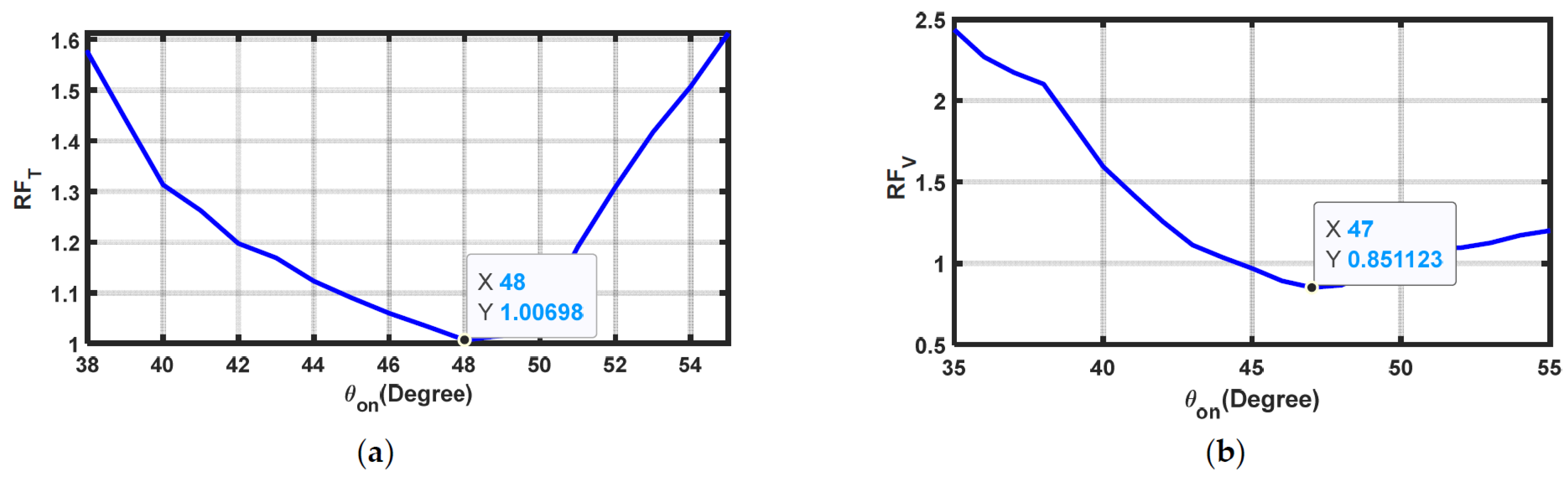
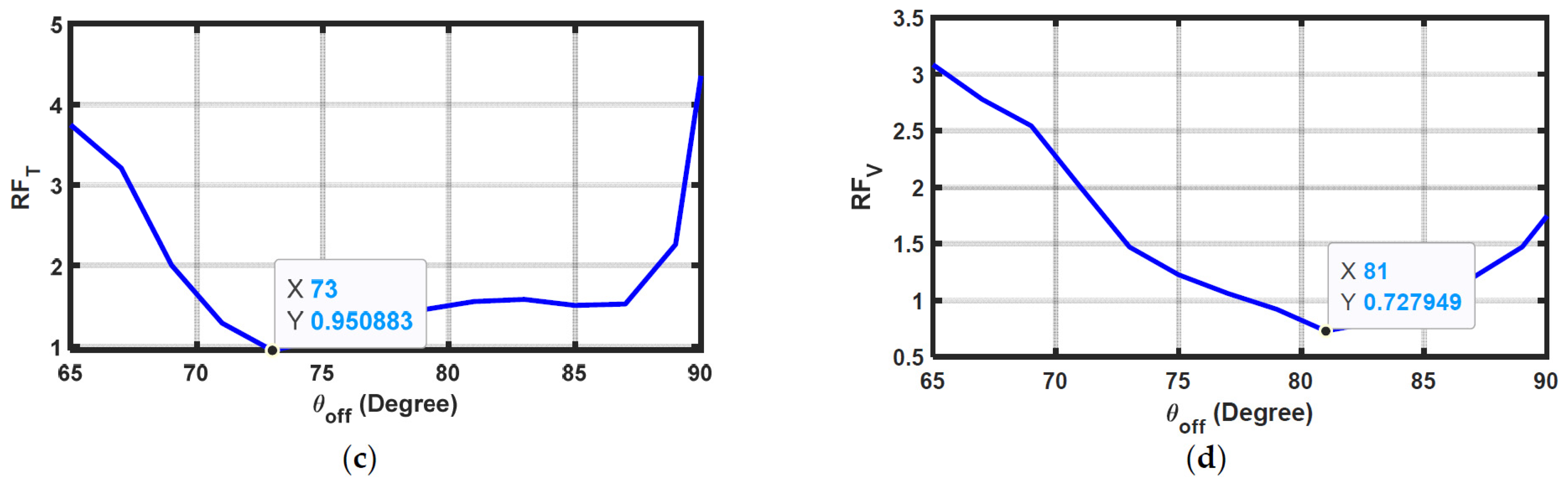
3. SRM Ripples with Varying Turn-On/Off Angles

The values of the turn-on and turn-off angles of SRM phases significantly influence SRM torque ripples. These angles have optimal values for each operating point, resulting in minimum ripples. Figure 2a,b illustrate the effect of changing θ o n while θ o f f is kept constant at 82° on R F T and R F V , respectively. At θ o n = 48°, R F T is minimized with a value of 1.007, while R F V is minimized at a turn-on angle of 47°. The effect of θ o f f on ripples is shown in Figure 2c,d, where different values of θ o f f are applied at θ o n = 45°. Again, θ o f f has an optimum value of 73° that results in the minimum R F T , while for the minimum R F V , its value is 81°.

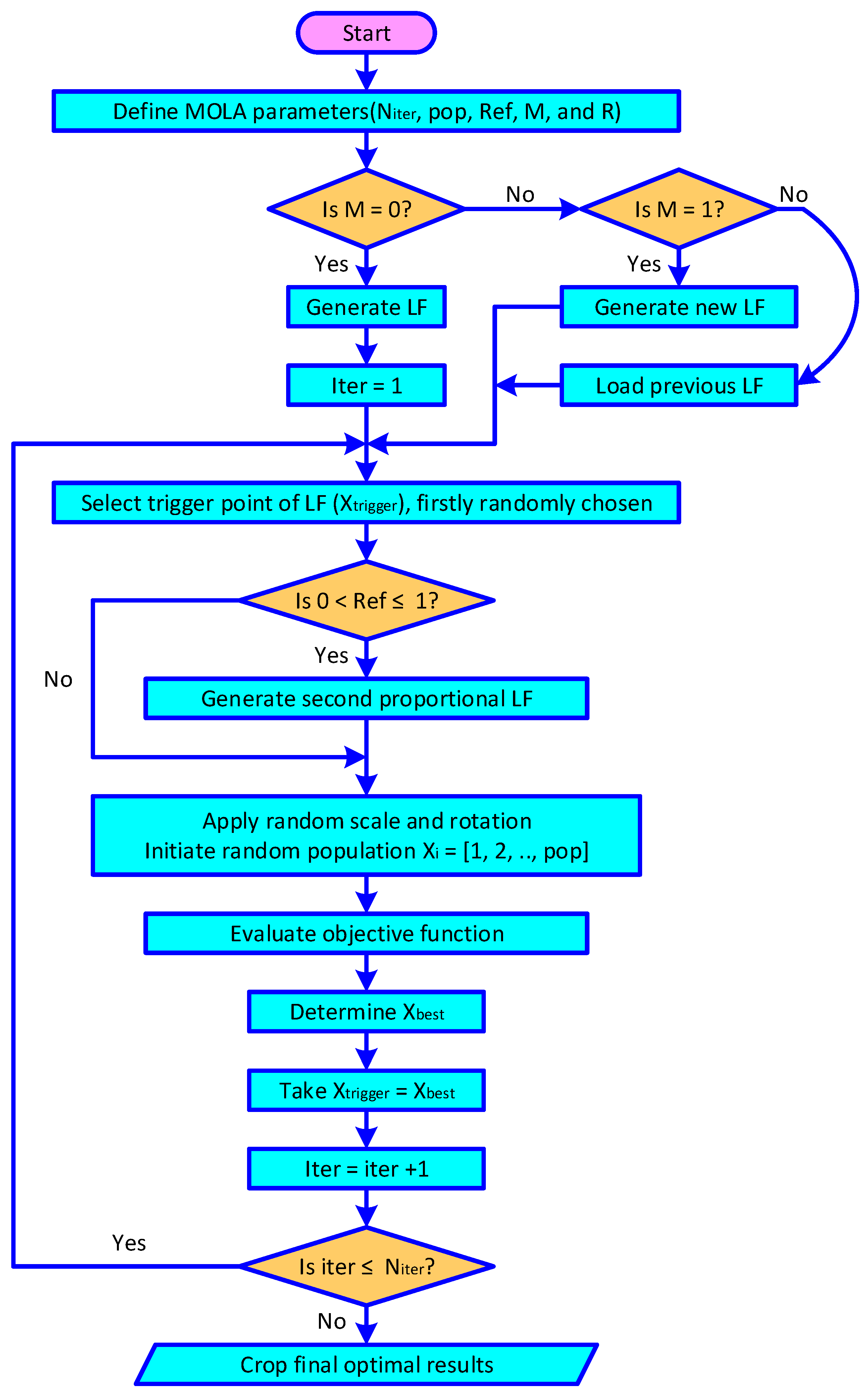
4. Overview of Lichtenberg Optimization Algorithms

The MOLA is a meta-heuristic optimization technique designed to address multiple objectives, drawing inspiration from the radial propagation of intra-cloud lightning and the formation of Lichtenberg figures. MOLA employs a hybrid optimization approach that integrates population-based and trajectory-based strategies. By leveraging Lichtenberg figures of varying sizes and rotational adjustments in each iteration, the algorithm enhances both exploration and exploitation, effectively distributing evaluation points across the objective function.
Lichtenberg was the first to examine the phenomenon of electric discharge propagation in dielectric materials, which results in random, branched, and complex patterns. The LA utilizes Lichtenberg figures (LFs) as a framework for developing the optimizer. The algorithm generates LFs based on the diffusion-limited aggregation theory, initially suggested by Witten and Sander [46,47].
The LF is a cartesian plane plot representing particles’ random movement to form a cluster and can be drawn with different sizes, slopes, or starting points. The LF is constructed with a fixed particle positioned at the center. For a number of particles (Np), each particle randomly moves toward the fixed point, sticking to it and becoming part of the cluster according to the stickiness coefficient (S). In the search space, if a particle moves beyond a radius slightly larger than Rc (the creation radius defines the construction space), it is eliminated, and a new particle begins its random walk.
Initially, the extracted LF is plotted with the exact size of the search space and its center aligned to the center of the space. The figure can be resized and rotated randomly in each iteration to enhance the algorithm’s exploration and exploitation abilities. A refinement factor (ref) ranging from 0 to 1 is applied in each iteration to generate a second LF with the same center point and rotation but which is smaller than the first LF. The smaller figure enhances the local search. When ref = 0, only the primary LF is active in the optimization process in every iteration.
Not all points of the LF are used for evaluating the objective function; only the designated population points (pop) are utilized. The population size is defined at the beginning of the algorithm and is typically set to ten times the number of problem design variables. These population points (represented by black dots) are strategically distributed across the LF and are consistently validated to ensure that they remain within the search space. This structured approach classifies the LA as a hybrid method, integrating population- and trajectory-based strategies. This unique hybrid mechanism significantly enhances the algorithm’s exploration and exploitation capabilities in its mono-objective version, demonstrating strong potential for its extension to multi-objective optimization.
Another parameter, known as the switching factor (M), controls how the LF is changed in the algorithm’s input data. The factor M has three values of 0, 1, or 2. When M = 0, a single LF is generated at the start of the program and remains unchanged throughout all iterations. A new figure is created if M = 1. When M = 2, the algorithm utilizes a formerly saved figure. Furthermore, the number of iterations (Niter) is first defined as a configuration parameter. A flowchart summarizing the operation of the LA is shown in Figure 3.
The solutions produced by evaluating objective function are compared using the Pareto dominance principle. Non-dominated solutions are retained in the solution space, while dominated solutions are discarded. The set of non-dominated solutions in each iteration forms the current Pareto front, which progressively converges toward the actual Pareto front over successive iterations. In the MOLA, all points on the current Pareto front serve as potential candidates for generating new LF. In each iteration, one of these points is randomly selected to create an LF, guiding the search toward different regions of the solution space that yield improved objective function values.
The MOLA is employed in this paper for the following reasons:
i-
Its fractal nature allows the method to efficiently explore a vast search space and identify global optima in complex problems with many variables.
ii-
The algorithm effectively balances exploitation (refining solutions near optimal ones) and exploration (searching new regions), fostering the pursuit of a global optimum while minimizing the risk of premature convergence to local optima.
iii-
The fractal-like structure of the search space allows for the possibility of multiple solutions.
To determine the most suitable solution among the MOLA-offered Pareto front solutions, the procedures of the technique of the order of preference by similarity to the ideal solution (TOPSIS) were applied. Huang and Yoon [48] developed TOPSIS, which depends on calculating the shortest distance among alternatives and sorting them accordingly, as described in [49,50].

5. Simulations and Discussions

This section details how the three objective functions were optimized both individually and concurrently to investigate their effect on system performance as separate and combined objectives. Therefore, two study scenarios are presented in this section as follows. Particle swarm optimization (PSO), a well-known algorithm, was used to optimize the targeted objectives individually [51], and the stochastic fractional search (SFS) algorithm [52] was also applied for comparison. The optimum decision parameters were determined with varying motor operating conditions regarding the load torque and the controlled speed.

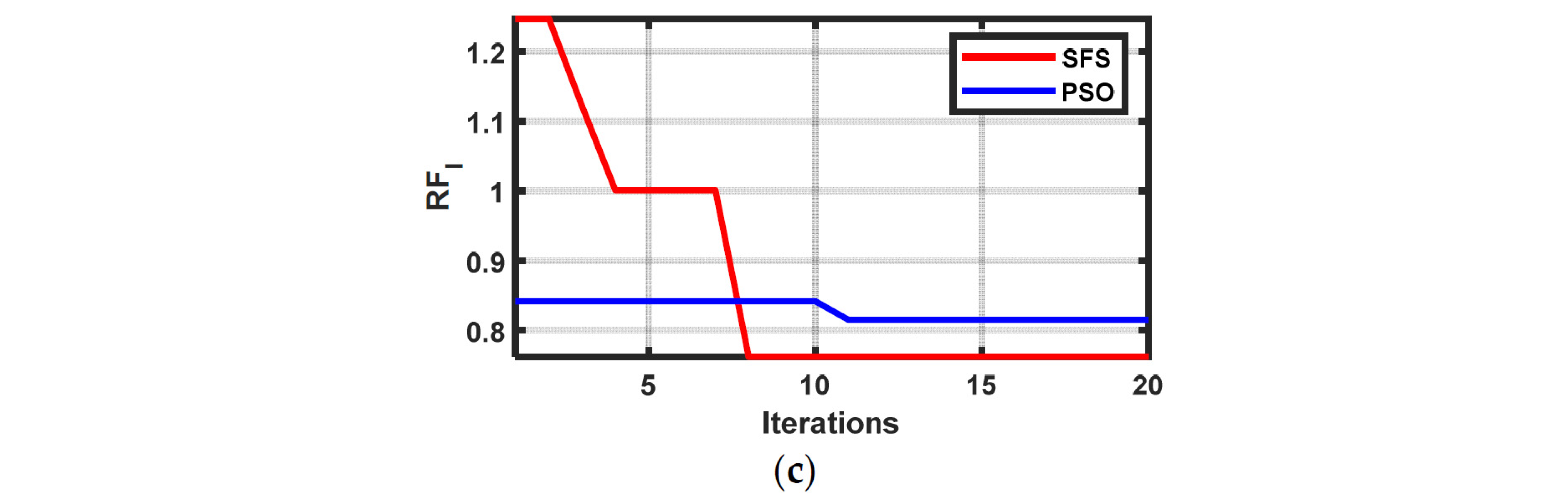
5.1. Single-Objective Scenario

In this scenario, PSO was applied to the three objective functions individually, and the cropped results were compared with those obtained by the SFS optimizer. This comparison was crucial to validate the solution quality obtained by both algorithms. Cropped results with R F T , R F V , and R F I are listed in Table 1, Table 2, and Table 3, respectively. No significant differences existed between the final values of the three objectives reached by the two algorithms, even with different decision variables. Both the PSO and SFS achieved comparable minimum R F T values (e.g., 0.8352 for PSO and 0.83402 for SFS at 20 Nm, 1000 rpm). The optimal turn-on and turn-off angles varied with operating conditions, highlighting the need for adaptive control. The lowest R F V values were 0.0851 (PSO) and 0.0847 (SFS) at 15 Nm and 2000 rpm, where R F I was minimized to 0.0006 for both algorithms under high-speed conditions (2000 rpm). Samples of the convergence trace with a load torque of 20 N.m and reference speed of 1000 rpm of the three objectives are shown in Figure 4. The two algorithms converged in 20 iterations despite having different initial values for the objectives. The SFS showed slight advantages in certain cases (e.g., lower RFI at high speeds), but PSO was more consistent across operating conditions.
The analyzed results were used to illustrate the PEMFC system; a test case was simulated with a load torque of 10 N·m and a motor speed of 2000 rpm. Since there was no significant difference between the final objectives obtained by PSO and the SFS, the results of the PSO are used to test the system. The system response with the analyzed results when RFT was minimized is illustrated in Figure 5. Figure 5a–f represent the PEMFC current, voltage, DC-link voltage, SRM torque, current, and speed, respectively. As shown in Figure 5d,e, the primary sources of ripples in the system were the SRM current and torque ripples, which were reflected in the PEMFC current ripples.
Therefore, minimizing the RFT was crucial for improving the performance of the PEMFC system. Figure 5 shows that minimizing RFT also reduced PEMFC current ripples, confirming the ripple propagation from the SRM to the fuel cell.
The system response under identical operating conditions of 10 N·m and 1000 rpm with the RFV objective is presented in Figure 6. There are no significant variations in the system responses presented in Figure 5 and Figure 6. However, Figure 6c shows a slight improvement in the DC-link voltage ripples. This is the expected response, as the target objective function in this case is RFV. Figure 7 shows the same response with the RFI objective; in this case, the responses are very close to those shown in Figure 5. It can be concluded that targeting any of the three objectives had nearly the same potential to reduce the PEMFC system ripples.
In [36,39], the authors proposed performance optimization methods for PEMFC-SRM systems. However, the system presented in this paper differs in several key aspects, including the DC-link voltage controller, SRM current controllers, fuel cell controllers, and the adopted objective functions. The objective functions and decision variables used in this study are listed in Table 4. Furthermore, the results obtained using the particle swarm optimization (PSO) algorithm for the 10 N·m case are presented in Table 4, alongside the results from [36,39], which employed the Dragonfly optimizer. It is observed that the targeted objective (highlighted in bold in Table 4) consistently achieved the highest value in each case.

5.2. Multi-Objective Scenario

In this scenario, the three objectives were simultaneously optimized using MOLA and the multi-objective Dragonfly (MODF) algorithm [53]. MODF was used in this article because it was applied to a similar system in [36] to enhance the torque smoothness factor, torque-to-amperage ratio, and PEMFC efficiency. The results from [36] demonstrated that MODF outperformed the well-established genetic algorithm.
The cropped results are listed in Table 5. The two algorithms produced different non-dominated Pareto front solutions. The best solution was selected according to the TOPSIS algorithm, as indicated in Figure 8a–f, with a load torque of 20 N.m and speeds of 1000 rpm, 1500 rpm, and 2000 rpm.
Based on the obtained Pareto front non-dominated solutions, MOLA and MODF had different selected parameters according to the TOPSIS method. For example, the objectives selected by MOLA with 20 N.m and 1000 rpm were RFT = 1.1198, RFV = 0.1325, and RFI = 0.5814, while with MODF, RFT = 0.8408, RFV = 0.1703, and RFI = 0.7840. MOLA outperformed MODF in some scenarios (e.g., lower RFV and RFI), while MODF yielded better RFT values in others. The system response is illustrated in Figure 9 at a speed of 2000 rpm and a load torque of 10 N.m.
Optimizing any single objective (RFT, RFV, or RFI) led to ripple reductions across the system, but trade-offs existed (e.g., minimizing RFT did not always guarantee the lowest RFV). Multi-objective optimization (MOLA/MODF) provided Pareto-optimal solutions, balancing trade-offs between torque, voltage, and current ripples. While single-objective optimization is efficient for targeted improvements, multi-objective optimization offers a more balanced and realistic solution for complex systems like PEMFC-SRM drives. The choice depends on whether the priority is speed, simplicity, or holistic performance.

6. Conclusions

The article’s conclusion emphasizes the effectiveness of the proposed optimization method in reducing ripples through the PEMFC system. The study demonstrates improvements in system performance by optimizing three key objectives—SRM torque ripple factor, DC-link voltage ripple factor, and PEMFC current ripple factor both individually and concurrently. The results indicate that the main contributors to ripples in the PEMFC system are the SRM current and torque ripples, which directly affect the fuel cell’s current stability. Among the optimization techniques employed, the results obtained from PSO and SFS show minimal differences, with PSO results used for final testing. In the multi-objective scenario, three objectives: the SRM torque ripple factor, the DC-link voltage ripple factor, and the PEMFC current ripple factor are optimized simultaneously using MOLA and MODF. The results reveal that both algorithms produce different non-dominated Pareto front solutions, with the best solution selected using the TOPSIS method. The findings confirm that optimizing all three objectives concurrently leads to reduced system ripples, particularly under varying load torque and speed conditions.

Author Contributions

Conceptualization, M.A.E.-H. and E.A.E.-H.; Formal analysis, M.A.E.-H., M.S., A.K. and E.A.E.-H.; Investigation, M.A.E.-H. and E.A.E.-H.; Methodology, M.A.E.-H., M.S., A.K. and E.A.E.-H.; Supervision, M.S. and A.K.; Validation, M.S. and A.K.; Visualization, M.A.E.-H. and E.A.E.-H.; Writing—original draft, M.A.E.-H. and E.A.E.-H.; Writing—review and editing, M.S. and A.K. All authors have read and agreed to the published version of the manuscript.

Funding

The research leading to these results received funding from the Ministry of Higher Education, Research, and Innovation (MoHERI) of the Sultanate of Oman under the Block Funding Program. Agreement No [MoHERI/BFP/ASU/2023/300].

Data Availability Statement

The original contributions presented in the study are included in the article; further inquiries can be directed to the corresponding author.

Acknowledgments

This research work was supported by Ministry of Higher Education Research and Innovation (MoHERI) Muscat of the Sultanate of Oman and A’Sharqiyah University, Ibra of the Sultanate of Oman, and we fully acknowledge MoHERI and A’Sharqiyah University Oman for their necessary financial support for continuing this research work.

Conflicts of Interest

The authors declare no conflicts of interest.

Abbreviations

  • The following abbreviations are used in this manuscript:
ANNArtificial neural network
ASTAverage starting torque
BSBoost converter
DTCDirect torque control
IGBTIntegrated gate bipolar transistor
LALichtenberg algorithm
LFsLichtenberg figures
MODFMulti-objective Dragonfly
MOLAMulti-objective Lichtenberg algorithm
PEMFCProton exchange membrane fuel cell
PSOParticle swarm optimization
SCSupercapacitor
SFSStochastic fractional search
SRMSwitched reluctance motor
TARTorque/ampere ratio
TSFTorque smoothness factor
UPSUninterruptible power supply

References

  1. Rahman, K.M.; Fahimi, B.; Suresh, G.; Rajarathnam, A.; Ehsani, M. Advantages of Switched Reluctance Motor Applications to EV and HEV: Design and Control Issues. IEEE Trans. Ind. Appl. 2000, 36, 111–121. [Google Scholar] [CrossRef]
  2. Ramya, K.C.; Ramani, J.G.; Sridevi, A.; Rai, R.S.; Shirley, D.R.A. Analysis of the Different Types of Electric Motors Used in Electric Vehicles. In E-Mobility; Kathiresh, M., Kanagachidambaresan, G.R., Williamson, S.S., Eds.; EAI/Springer Innovations in Communication and Computing; Springer: Cham, Switzerland, 2022. [Google Scholar] [CrossRef]
  3. Valdez-Resendiz, J.E.; Rosas-Caro, J.C.; Sanchez, V.M.; Lopez-Nunez, A.R. Experimental study of a fuel cell stack performance operating with a power electronics converter with high-frequency current ripple. Int. J. Hydrogen Energy 2025, 108, 66–75. [Google Scholar] [CrossRef]
  4. Parache, F.; Schneider, H.; Turpin, C.; Richet, N.; Debellemanière, O.; Bru, É.; Thieu, A.T.; Bertail, C.; Marot, C. Impact of Power Converter Current Ripple on the Degradation of PEM Electrolyzer Performances. Membranes 2022, 12, 109. [Google Scholar] [CrossRef] [PubMed]
  5. Kim, J.; Lee, I.; Tak, Y.; Cho, B.H. Impedance-based diagnosis of polymer electrolyte membrane fuel cell failures associated with a low frequency ripple current. Renew. Energy 2013, 51, 302–309. [Google Scholar] [CrossRef]
  6. Gürlek, Y.; Joos, O.; Lang, C.; Ackerl, M.; Dold, R.; Basler, T.; Neuburger, M. Analysis on the Impact of Current Ripples in Fuel Cell Electric Heavy-Duty Trucks. In Proceedings of the 2023 25th European Conference on Power Electronics and Applications (EPE’23 ECCE Europe), Aalborg, Denmark, 4–8 September 2023. [Google Scholar] [CrossRef]
  7. Zhan, Y.; Guo, Y.; Zhu, J.; Liang, B.; Yang, B. Comprehensive influences measurement and analysis of power converter low frequency current ripple on PEM fuel cell. Int. J. Hydrogen Energy 2019, 44, 31352–31359. [Google Scholar] [CrossRef]
  8. Yildiz, E.; Vural, B.; Akar, F. Current ripple minimization of a PEM fuel cell via an interleaved converter to prolong the stack life. In Proceedings of the 19th International Symposium on Electrical Apparatus and Technologies (SIELA), Bourgas, Bulgaria, 29 May–1 June 2016; pp. 1–4. [Google Scholar] [CrossRef]
  9. Zhan, Y.; Guo, Y.; Zhu, J.; Li, L. Performance comparison of input current ripple reduction methods in UPS applications with hybrid PEM fuel cell/supercapacitor power sources. Int. J. Electr. Power Energy Syst. 2015, 64, 96–103. [Google Scholar] [CrossRef]
  10. Fasdi, N.; Abd-Rahim, N.; Rohani, S.; Al-Turki, Y. Parallel Inductor Multilevel Current Source Inverter for Input Ripple Current Reduction in PEM Fuel Cell Applications. IETE J. Res. 2018, 66, 505–517. [Google Scholar] [CrossRef]
  11. Li, S.; Zhang, S.; Habetler, T.G.; Harley, R.G. Modeling, design optimization, and applications of switched reluctance machines—A review. EEE Trans. Ind. Appl. 2019, 55, 2660–2681. [Google Scholar] [CrossRef]
  12. Mohanraj, D.; Gopalakrishnan, J.; Chokkalingam, B.; Mihet-Popa, L. Critical aspects of electric motor drive controllers and mitigation of torque ripple—Review. IEEE Access 2022, 10, 73635–73674. [Google Scholar] [CrossRef]
  13. Deng, X.; Mecrow, B.; Wu, H.; Martin, R. Design and Development of Low Torque Ripple Variable-Speed Drive System with Six-Phase Switched Reluctance Motors. IEEE Trans. Energy Convers. 2018, 33, 420–429. [Google Scholar] [CrossRef]
  14. Deng, X.; Mecrow, B.; Wu, H.; Martin, R.; Gai, Y. Cost-Effective and High-Efficiency Variable-Speed Switched Reluctance Drives with Ring-Connected Winding Configuration. IEEE Trans. Energy Convers. 2019, 34, 120–129. [Google Scholar] [CrossRef]
  15. Röth, C.; Milde, F.; Trebbels, D.; Schmidt, J.; Doppelbauer, M. A Stator with Offset Segments and a Double Stator Design for the Reduction of Torque Ripple of a Switched Reluctance Motor. IEEE Trans. Energy Convers. 2022, 37, 1233–1240. [Google Scholar] [CrossRef]
  16. Davarpanah, G.; Faiz, J. A Novel Structure of Switched Reluctance Machine with Higher Mean Torque and Lower Torque Ripple. IEEE Trans. Energy Convers. 2020, 35, 1859–1867. [Google Scholar] [CrossRef]
  17. Mehta, S.; Kabir, M.A.; Pramod, P.; Husain, I. Segmented Rotor Mutually Coupled Switched Reluctance Machine for Low Torque Ripple Applications. EEE Trans. Ind. Appl. 2021, 57, 3582–3594. [Google Scholar] [CrossRef]
  18. Mohammadi, S.E.M.; Chen, P.; Moallem, M.; Fahimi, B.; Kiani, M. An Alternate Rotor Geometry for Switched Reluctance Machine with Reduced Torque Ripple. IEEE Trans. Energy Convers. 2023, 38, 939–947. [Google Scholar] [CrossRef]
  19. Mohanraj, D.; Gopalakrishnan, J.; Chokkalingam, B.; Ojo, J.O. An Enhanced Model Predictive Direct Torque Control of SRM Drive Based on a Novel Modified Switching Strategy for Low Torque Ripple. IEEE J. Emerg. Sel. Top. Power Electron. 2024, 12, 2203–2213. [Google Scholar] [CrossRef]
  20. Li, H.; Bilgin, B.; Emadi, A. An Improved Torque Sharing Function for Torque Ripple Reduction in Switched Reluctance Machines. IEEE Trans. Power Electron. 2019, 34, 1635–1644. [Google Scholar] [CrossRef]
  21. Sun, X.; Wu, J.; Lei, G.; Guo, Y.; Zhu, J. Torque Ripple Reduction of SRM Drive Using Improved Direct Torque Control with Sliding Mode Controller and Observer. IEEE Trans. Ind. Electron. 2021, 68, 9334–9345. [Google Scholar] [CrossRef]
  22. Deng, X.; Mecrow, B. A Direct Energy Control Technique for Torque Ripple and DC-link Voltage Ripple Reduction in Switched Reluctance Drive Systems. In Proceedings of the International Conference on Electrical Machines (ICEM), Gothenburg, Sweden, 23–26 August 2020. [Google Scholar] [CrossRef]
  23. Du, L.; Gu, B.; Lai, J.-S.J.; Swint, E. Control of pseudo-sinusoidal switched reluctance motor with zero torque ripple and reduced input current ripple. In Proceedings of the 2013 IEEE Energy Conversion Congress and Exposition, Denver, CO, USA, 15–19 September 2013. [Google Scholar] [CrossRef]
  24. Ge, L.; Zhong, J.; Cheng, Q.; Fan, Z.; Song, S.; De Doncker, R.W. Model Predictive Control of Switched Reluctance Machines for Suppressing Torque and Source Current Ripples Under Bus Voltage Fluctuation. IEEE Trans. Ind. Electron. 2023, 70, 11013–11021. [Google Scholar] [CrossRef]
  25. Haque, M.E.; Chowdhury, A.; Chowdhury, S.M.; Harasis, S.; Das, S.; Sozer, Y.; Gundogmus, O.; Vadamodala, L.; Venegas, F.; Colavincenzo, D.; et al. DC-Link Current Ripple Reduction in Switched Reluctance Machine Drives. IEEE Trans. Ind. Appl. 2021, 57, 1429–1439. [Google Scholar] [CrossRef]
  26. Kimpara, M.L.M.; Reis, R.R.C.; Da Silva, L.E.B.; Pinto, J.O.P.; Fahimi, B. A Two-Step Control Approach for Torque Ripple and Vibration Reduction in Switched Reluctance Motor Drives. IEEE Access 2022, 10, 82106–82118. [Google Scholar] [CrossRef]
  27. Saha, N.; Panda, S.; Sahoo, D.K. Modified Whale Optimisation Technique for Combined Objective of Torque Ripple Minimization & Speed Control of SRM Drive. In Proceedings of the 2020 3rd International Conference on Energy, Power and Environment: Towards Clean Energy Technologies, Shillong, Meghalaya, India, 5–7 March 2021. [Google Scholar] [CrossRef]
  28. Jing, B.; Dang, X.; Liu, Z.; Long, S. Torque ripple suppression of switched reluctance motor based on fuzzy indirect instant torque control. IEEE Access 2022, 10, 75472–75481. [Google Scholar] [CrossRef]
  29. Elhay, E.A.; Elkholy, M.M. Optimal dynamic and steady-state performance of switched reluctance motor using water cycle algorithm. IEEJ Trans. Electr. Electron. Eng. 2018, 13, 882–890. [Google Scholar] [CrossRef]
  30. Pereira, J.L.J.; Oliver, G.A.; Francisco, M.B.; Cunha, S.S., Jr.; Gomes, G.F. Multi-objective Lichtenberg Algorithm: A Hybrid Physics-based Meta-heuristic for solving Engineering Problems. Expert Syst. Appl. 2022, 187, 115939. [Google Scholar] [CrossRef]
  31. Pereira, J.L.J.; Francisco, M.B.; Diniz, C.A.; Oliver, G.A.; Cunha, S.S.; Gomes, G.F. Lichtenberg algorithm: A novel hybrid PHYSICS-based metaheuristic for global optimization. Expert Syst. Appl. 2021, 170, 114522. [Google Scholar] [CrossRef]
  32. Pereira, J.L.J.; Chuman, M.; Cunha, S.S., Jr.; Gomes, G.F. Lichtenberg optimization algorithm applied to crack tip identification in thin platelike structures. Eng. Comput. 2021, 38, 151–166. [Google Scholar] [CrossRef]
  33. Pereira, J.; Francisco, M.B.; Cunha, S.S., Jr.; Gomes, G.F. A powerful Lichtenberg optimization algorithm: A damage identification case study. Eng. Appl. Artif. Intell. 2021, 97, 104055. [Google Scholar] [CrossRef]
  34. Francisco, M.B.; Junqueira, D.M.; Oliver, G.A.; Pereira, J.L.J.; da Cunha, S.S., Jr.; Gomes, G.F. Design optimizations of carbon fibre reinforced polymer isogrid lower limb prosthesis using particle swarm optimization and Lichtenberg algorithm. Eng. Optim. 2021, 53, 1922–1945. [Google Scholar] [CrossRef]
  35. Allaou, B.; Asnoune, K.; Mebarki, B. Energy management of PEM fuel cell/supercapacitor hybrid power sources for an electric vehicle. Int. J. Hydrogen Energy 2017, 42, 21158–21166. [Google Scholar] [CrossRef]
  36. El-Hay, E.A.; El-Hameed, M.A.; El-Fergany, A.A. Performance enhancement of autonomous system comprising proton exchange membrane fuel cells and switched reluctance motor. Energy 2018, 163, 699–711. [Google Scholar] [CrossRef]
  37. Fathabadi, H. Novel fuel cell/battery/supercapacitor hybrid power source for fuel cell hybrid electric vehicles. Energy 2018, 143, 467–477. [Google Scholar] [CrossRef]
  38. Odeim, F.; Roes, J.; Heinzel, A. Power Management Optimization of a Fuel Cell/Battery/Supercapacitor Hybrid System for Transit Bus Applications. IEEE Trans. Veh. Technol. 2016, 65, 5783–5788. [Google Scholar] [CrossRef]
  39. El-Hay, E.A.; El-Hameed, M.A.; El-Fergany, A.A. Improved performance of PEM fuel cells stack feeding switched reluctance motor using multi-objective dragonfly optimizer. Neural Comput. Appl. 2019, 31, 6909–6924. [Google Scholar] [CrossRef]
  40. Oldham, K.B. A Gouy-Chapman-Stern model of the double layer at a (metal)/(ionic liquid) interface. J. Electroanal. Chem. 2008, 613, 131–138. [Google Scholar] [CrossRef]
  41. Xu, N.; Riley, J. Nonlinear analysis of a classical system: The double-layer capacitor. Electrochem. Commun. 2011, 13, 1077–1081. [Google Scholar] [CrossRef]
  42. Omar, N.; Monem, M.A.; Firouz, Y.; Salminen, J.; Smekens, J.; Hegazy, O.; Gaulous, H.; Mulder, G.; Van Den Bossche, P.; Coosemans, T.; et al. Lithium iron phosphate based battery—Assessment of the aging parameters and development of cycle life model. Appl. Energy 2014, 113, 1575–1585. [Google Scholar] [CrossRef]
  43. Saw, L.H.; Somasundaram, K.; Ye, Y.; Tay, A.A.O. Electro-thermal analysis of Lithium Iron Phosphate battery for electric vehicles. J. Power Sources 2014, 249, 231–238. [Google Scholar] [CrossRef]
  44. Tremblay, O.; Dessaint, L.A. Experimental Validation of a Battery Dynamic Model for EV Applications. World Electr. Veh. J. 2009, 3, 289–298. [Google Scholar] [CrossRef]
  45. Zhu, C.; Li, X.; Song, L.; Xiang, L. Development of a theoretically based thermal model for lithium-ion battery pack. J. Power Sources 2013, 223, 155–164. [Google Scholar] [CrossRef]
  46. Witten, T.A.; Sander, L.M. Diffusion-limited aggregation: A kinetic critical phenomenon. Phys. Rev. Lett. 1981, 47, 1400–1403. [Google Scholar] [CrossRef]
  47. Witten, T.A.; Sander, L.M. Diffusion-limited aggregation. Phys. Rev. Lett. 1983, 27, 5686–5697. [Google Scholar] [CrossRef]
  48. Huang, C.L.; Yoon, K. Multi Attribute Decision Making: Methods and Applications; Springer: New York, NY, USA, 1981. [Google Scholar]
  49. Kaya, T.; Kahraman, C. Multicriteria decision making in energy planning using a modified fuzzy TOPSIS methodology. Expert Syst. Appl. 2011, 38, 6577–6585. [Google Scholar] [CrossRef]
  50. Cristobal, S.; Ramon, J. Multi-Criteria Analysis in the Renewable Energy Industry, Green Energy and Technology; Springer: London, UK, 2012. [Google Scholar]
  51. Kennedy, J.; Eberhart, R. Particle Swarm Optimization. In Proceedings of the IEEE International Conference on Neural Networks IV, Perth, WA, Australia, 27 November–1 December 1995; pp. 1942–1948. [Google Scholar] [CrossRef]
  52. Salimi, H. Stochastic fractal search: A powerful metaheuristic algorithm. Knowl.-Based Syst. 2015, 75, 1–18. [Google Scholar] [CrossRef]
  53. Mirjalili, S. Dragonfly Algorithm: A New Meta-heuristic Optimization Technique for Solving Single-objective, Discrete, and Multi-objective Problems. Neural Comput. Appl. 2015, 27, 1053–1073. [Google Scholar] [CrossRef]
Figure 1. FC-SRM system’s schematic block diagram.
Energies 18 02004 g001
Figure 2. Effect of changing θ o n and θ o f f on R F T and R F V : (a) effect of changing θ o n on RFT; (b) effect of changing θ o n on RFV; (c) effect of changing θ o f f on RFT; (d) effect of changing θ o f f on RFT.
Energies 18 02004 g002aEnergies 18 02004 g002b
Figure 3. A flowchart summarizing the operation of the LA.
Energies 18 02004 g003
Figure 4. Convergence of PSO and SFS: (a) R F T ; (b) R F V ; (c) R F I .
Energies 18 02004 g004aEnergies 18 02004 g004b
Figure 5. System response when targeting RFT: (a) PEMFC current; (b) PEMFC voltage; (c) DC-link voltage; (d) SRM torque; (e) SRM current; (f) SRM speed.
Energies 18 02004 g005
Figure 6. System response when targeting RFV: (a) PEMFC current; (b) PEMFC voltage; (c) DC-link voltage; (d) SRM torque; (e) SRM current; (f) SRM speed.
Energies 18 02004 g006
Figure 7. System response when targeting RFI: (a) PEMFC current; (b) PEMFC voltage; (c) DC-link voltage; (d) SRM torque; (e) SRM current; (f) SRM speed.
Energies 18 02004 g007
Figure 8. Pareto front non-dominated solutions with MOLA at T L = 20 Nm and at (a) speed = 1000 rpm; (b) speed = 1500 rpm; (c) speed = 2000 rpm. Pareto front non-dominated solutions with MODF at T L = 20 Nm and at (d) speed = 1000 rpm; (e) speed = 1500 rpm; (f) speed = 2000 rpm.
Energies 18 02004 g008
Figure 9. System response with MOLA: (a) PEMFC current; (b) PEMFC voltage; (c) DC-link voltage; (d) SRM torque; (e) SRM current; (f) SRM speed.
Energies 18 02004 g009
Table 1. Results of PSO and SFS optimizers when targeting R F T .
Torque (Nm)101520
Speed (rpm)100015002000100015002000100015002000
θ o n (Degree)PSO48.179444.091550.222843.988046.392445.937047.077643.609349.7966
SFS48.470344.016547.904249.247043.392348.938948.200544.262449.7966
θ o f f (Degree)PSO78.224282.596082.709782.953477.684776.866477.419979.928879.7495
SFS78.879577.374879.152079.803076.584978.923478.659678.899884.3889
k p PSO0.46660.21800.30920.19840.00000.40730.00000.11700.2954
SFS0.01480.22780.26790.11180.16960.23300.23730.36160.1482
k i PSO579.5989445.6444349.2389419.5363440.9503536.6692573.3328464.2013563.5176
SFS568.2403464.2483373.9740517.7874369.5236494.6761381.6491440.2491.1486
R F T PSO1.22231.15271.05630.99740.91682.52420.83520.85042.2950
SFS1.46931.14321.04020.98890.92552.41330.834020.846222.3742
Table 2. Results of PSO and SFS optimizers when targeting R F V .
Torque (Nm)10 1520
Speed (rpm)100015002000100015002000100015002000
θ o n (Degree)PSO46.510544.747447.636144.328144.086646.309945.838647.628747.0839
SFS46.331747.536949.180445.413245.509647.447946.610448.123746.2041
θ o f f (Degree)PSO82.633775.494178.681784.940475.000080.926176.035182.500076.5700
SFS81.246275.138979.559775.980375.694279.200076.970678.729484.8362
k p PSO0.38710.48760.37320.00610.00840.50000.40230.50000.0531
SFS0.38440.46020.22380.17690.17170.25240.39100.09870.2533
k i PSO323.6789446.7317404.2172312.5365396.2236313.2306306.3635300.1970348.7012
SFS357.483394.3156347.3662325.8527362.9984303.8323383.3297309.6486691.3157
R F V PSO0.21480.24440.08510.27000.09680.51550.15830.51769.5034
SFS0.242420.237380.08470.23830.09770.48960.17080.50417.9081
Table 3. Results of PSO and SFS optimizers when targeting R F I .
Torque (Nm)10 1520
Speed (rpm)100015002000100015002000100015002000
θ o n (Degree)PSO44.097442.878544.589640.137946.714346.010938.761248.778748.4775
SFS40.870348.895242.616742.223046.324948.528250.795349.596349.8022
θ o f f (Degree)PSO86.969884.634481.969678.983983.102781.436275.515685.463087.1308
SFS76.303987.269779.140476.976275.653379.860476.085879.974183.3693
k p PSO0.05110.02200.40490.19930.12480.25290.28350.12470.0000
SFS0.19290.30930.14800.29450.14190.18230.36860.28580.1263
k i PSO333.0230440.0060654.9691517.9592350.0524485.9360601.6650598.2038319.5331
SFS328.7698369.4885602.4511323.3124374.8419616.4534336.7534470.3064379.4838
R F I PSO2.25921.72570.00061.85560.35280.00100.81500.00100.0010
SFS2.25681.66060.00061.79550.326220.00100.76200.00110.0010
Table 4. The results for the 10 N·m case, along with those reported in [36,39].
ItemPresent PaperRef. [36]Ref. [39]
Objectives
RFT
RFV
RFI
Torque/ampere ratio (TAR)
Torque smoothness factor (TSF)
Stack efficiency (ηstack)
TAR
TSF
Average starting torque (AST)
Decision variables
Turn-on angle
Turn-off angle
DC-link voltage PI controller gains
Turn-on angle
Turn-off angle
PEMFC temperature
Fuel and air pressures
Air flow rate
Turn-on angle
Turn-off angle
SRM current PI controller gains
1000 rpmRFTRFVRFITARTSFηstack %TARTSFAST
1.22230.27152.45491.50.2578.140.62580.263046.4432
1.37290.21482.38860.951.2277.250.55961.784861.1050
1.23760.23102.25921.330.3679.92Not mentioned
1500 rpm1.15270.27631.84991.540.2177.290.63390.413838.8810
1.16350.24441.79040.991.2977.130.55701.815263.6280
1.25170.26771.72571.560.2479.33Not mentioned
2000 rpm1.05630.10830.32081.630.350.020.69680.345634.2097
1.04640.08510.41161.051.476.070.60331.850845.2680
2.53600.60020.00061.570.3279.12Not mentioned
Table 5. Results of MOLA and MODF.
Torque (Nm)10 1520
Speed (rpm)100015002000100015002000100015002000
θ o n (Degree)MOLA50.212943.617947.740445.596446.202246.209347.851246.023351.4311
MODF45.815245.706749.636844.540746.448747.600051.500042.400047.6000
θ o f f (Degree)MOLA81.428175.312177.991875.950375.474483.382977.293480.665385.7743
MODF76.029776.650787.871375.630176.907584.794482.560279.608683.6344
k p MOLA0.50000.19550.03120.05560.35210.0000.30910.40380.5000
MODF0.01670.01060.02000.00000.02000.02000.00000.00000.0131
k i MOLA300.0000300.0000347.2399456.2041300.0000596.3592316.6290566.9783402.0087
MODF523.4516465.9377491.9917514.0998490.3249524.7088499.0793475.2724520.7434
R F T MOLA1.44041.18331.16701.05031.16802.25221.11982.27902.8467
MODF1.24591.12822.61111.06210.96432.29270.84080.88652.0465
R F V MOLA0.21230.22060.09340.28350.10199.23420.13257.477413.7054
MODF0.24530.09348.77820.16310.44608.98430.17030.388912.2459
R F I MOLA2.26651.58700.30551.91570.32430.00110.58140.00130.0010
MODF2.05300.45250.00111.16791.91050.00110.78401.23610.0011
Disclaimer/Publisher’s Note: The statements, opinions and data contained in all publications are solely those of the individual author(s) and contributor(s) and not of MDPI and/or the editor(s). MDPI and/or the editor(s) disclaim responsibility for any injury to people or property resulting from any ideas, methods, instructions or products referred to in the content.

