Article

Influence of Potential Well Depth on the Dual−Coupling Beam Energy Harvester: Modeling and Experimental Validation

College of Mechanical and Electrical Engineering, Qingdao University, Qingdao 266071, China
*
Author to whom correspondence should be addressed.
Energies 2025, 18(8), 1984; https://doi.org/10.3390/en18081984
Submission received: 24 February 2025 / Revised: 7 April 2025 / Accepted: 10 April 2025 / Published: 12 April 2025
(This article belongs to the Special Issue Innovations and Applications in Piezoelectric Energy Harvesting)

Abstract

This paper presents an investigation into the influence of varying potential well depths on the performance of a dual−coupled beam energy harvester (DEH). Firstly, three varying potential well depths were established with different polynomial coefficients of nonlinear restoring force and analyzed in simulation. Numerical results revealed that whether the initial potential well depth is shallow or not, the optimal power output can be attained when the stiffness of the coupling spring is a half of the monostable−to−bistable coupling spring stiffness, which was also validated by an experiment. Specifically, at a deeper initial potential well depth of 0.64 mJ, the system demonstrated superior energy conversion capabilities. Compared to traditional BEH and LEH, the output RMS voltage of Beam 1 and total RMS power of the DEH increased by 103.06% and 49.6%, respectively. The RMS power increased by 16.4% at a potential well depth of 0.9 mJ. In addition, regardless of the potential well depth, the DEH can always achieve the optimal operating bandwidth when the coupling spring stiffness is near the monostable−to−bistable transition region.

1. Introduction

With the proliferation of wireless sensor networks, the limitations of traditional chemical batteries in powering sensor nodes have become apparent [1,2]. Addressing this issue, the vibration energy harvesting technique has offered a sustainable solution [3,4,5,6,7,8]. Particularly, piezoelectric energy harvesters (PEHs) have garnered widespread attention due to their structural simplicity and small volume [9,10,11]. However, linear piezoelectric energy harvesters (LEHs) can harvest the optimal energy only when the resonant frequency of the harvester matches the external excitation frequency. In other words, the performance of the LEH will significantly degrade when subjected to varying environmental vibration frequencies [12].
To broaden the bandwidth of the PEH, some approaches have been proposed, such as multi−modal techniques [13,14,15,16], resonance tuning approaches [17,18,19], and nonlinear techniques [20,21,22,23,24,25,26]. In particular, the nonlinear techniques mainly include monostable duffing, impact and bistable oscillator designs [27,28,29,30]. Monostable technology can improve energy collection efficiency through adaptive control design but usually requires high energy input and complex support circuits to achieve high electromechanical coupling efficiency [31]. Bistable energy harvesters (BEHs) have distinguished themselves by enabling high−energy inter−well oscillations over broad operation bandwidth [32,33]. However, under low−level excitation (below the threshold of inter−well oscillations), the BEH will exhibit small−amplitude intra−well oscillations or chaotic motions, which finally lead to a significant reduction in energy harvesting performance [34,35].
In order to solve this problem, two methods are generally employed: reducing the barrier height and applying additional external excitation [36]. For lowering the potential barrier, tristable structures and quad−stable structures have been proposed [37,38,39]. Lan et al. [40] proposed an improved bistable energy harvester, which decreases the potential barrier height by adding a small magnet between two fixed external magnets. Mei et al. [41] introduced a quad−stable energy harvester with lower potential barriers, which can enhance energy harvesting in low−frequency rotational motion. Zhou et al. [42] investigated the output responses of the asymmetric tristable energy harvester, which can more easily jump into the inter−well motion and output the higher voltage under low−level excitations. Xu and Zhou [43] described an energy harvester with the decoupled bistable potential (DBEH) and discussed the influence of barrier height and width on output responses and the multi−solution range. Moreover, Margielewicz et al. [44] compared the efficiency of energy harvesting for bistable and tristable systems when the corresponding depth of the potential well and the width of the characteristics are the same. Daqaq [45] investigated an asymmetric quadratic potential and demonstrated the influence of asymmetric potential wells on the output power.
On the other hand, the BEH can achieve high−energy inter−well oscillation by changing initial conditions or applying perturbations. The external perturbations can change the intra−well oscillation or chaotic motion of the oscillator into large−amplitude oscillation [20,46]. The energy harvesting performance of the mechanical plucking energy harvester can be improved by using beneficial perturbations [47]. Lan et al. [48] proposed a bistable energy harvester with an impact facility by introducing two stops. Results reveal that a proper impact can change an intra−well motion into an inter−well motion. Fan et al. [49] introduced a parametrically excited beam−based vibration energy harvester, which can integrate an oscillating substructure and facilitate snap−through transitions. It should be noted that the external disturbance or other disturbance still requires maintaining a particular level to achieve large inter−well oscillation; otherwise, the inter−well movement resulting from the disturbance will only exist for a short period of time [50].
Chen et al. [51] combined the above two methods and proposed a novel dual−coupling beam energy harvester (DEH) that consisted of a BEH, a LEH, and a coupling spring. The DEH introduces an additional linear oscillator and coupling spring to a typical BEH, which can not only lower the potential well depth, but can also provide a disturbance. Thus, DEH can achieve high−energy inter−well oscillations at the low−level excitation. However, Chen et al. only analyzed the output performance of DEH at a potential well depth of 0.5 mJ under sweep excitation. Indeed, some mechanical vibrations in the environment are likely to be present around a fixed frequency. Therefore, it is interesting to investigate the performance of the DEH under constant frequency excitation or the influence of different potential well depths.
This paper investigates the influence of potential well depth on the performance of the DEH under constant frequency excitation. The remainder of this paper is organized as follows. In Section 2, the structure and the mathematical model of the DEH are described. Section 3 introduces the experiment setup and the identification of system parameters. Furthermore, the static nonlinear restoring force and potential energy with different coupling spring stiffnesses under various potential well depths are elaborated. Section 4 analyzes the energy harvesting performance of the DEH with various potential well depths by numerical simulation and experiments. The optimal stiffness of the coupling spring under constant frequency excitation is also discussed in this section. Conclusions are provided in Section 5.

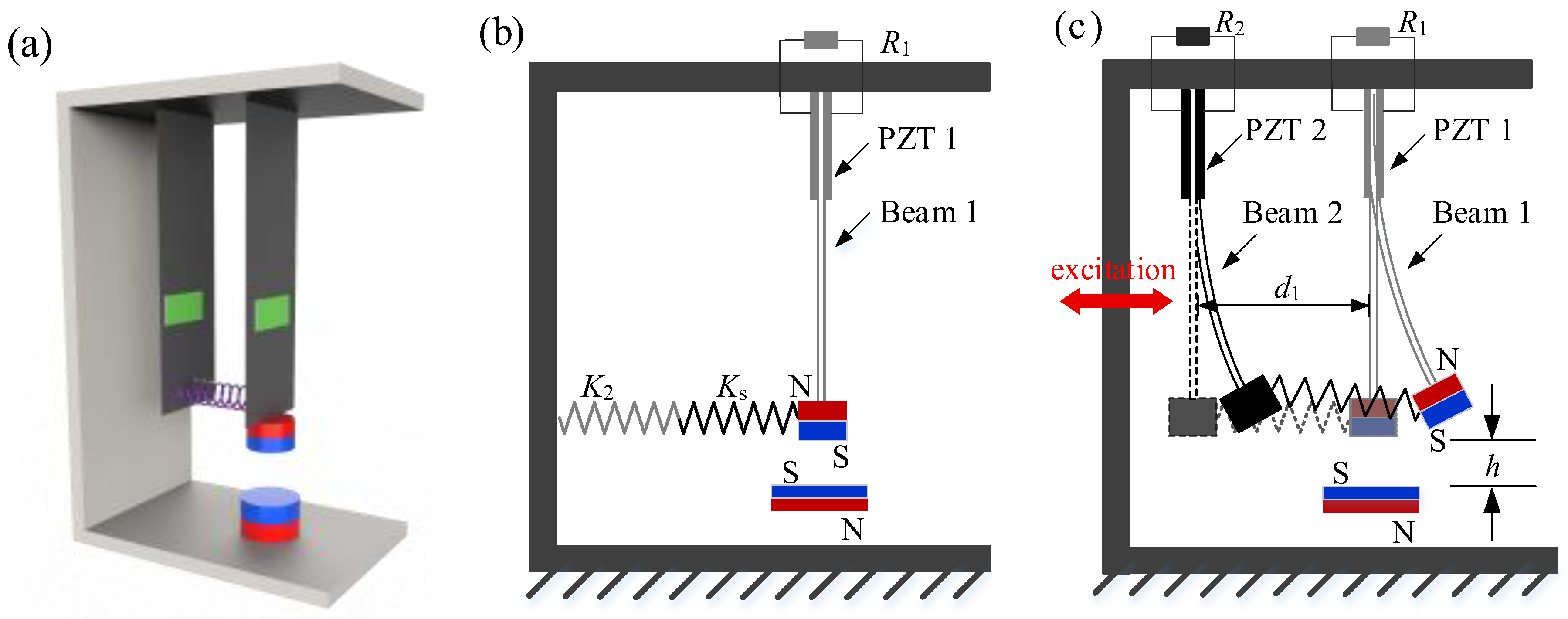
2. Structure and Mathematical Model of DEH

Figure 1a shows the basic structure of the DEH, consisting of two piezoelectric cantilever beams interconnected by a coupling spring. Beam 1 is a bistable piezoelectric beam with a permanent magnet fixed at its free end, which is repulsed by the magnet on the base. Beam 2 is a traditional linear piezoelectric beam with a non−magnetic tip−mass. The coupling spring is affixed at the free ends of these two beams. It should be noted that the distance between the two beams (d1) is quite large to avoid collision during vibration. The electromechanical control equations of the DEH are described by the following:
M 1 d 2 x 1 d t 2 + K 1 x 1 ( t ) + C 1 d x 1 d t θ 1 v 1 ( t ) + F m + F s = F b ( t ) C p 1 d v 1 d t + v 1 ( t ) R 1 + θ 1 d x 1 d t = 0 M 2 d 2 x 2 d t 2 + K 2 x 2 ( t ) + C 2 d x 2 d t θ 2 v 2 ( t ) F s = F b ( t ) C p 2 d v 2 d t + v 2 ( t ) R 2 + θ 2 d x 2 d t = 0
where the electromechanical system’s parameters are defined by the respective masses M1 and M2 for Beam 1 and Beam 2, the damping coefficients C1 and C2, and the stiffness coefficients K1 and K2. The magnetic force is denoted by Fm. θ1 and θ2 represent the electromechanical coupling coefficients. The capacitances are represented by CP1 and CP2, while R1 and R2 denote the load resistances. The relative displacements of the beams with respect to the base are given by x1(t) and x2(t), and the output voltages are v1(t) and v2(t). Ks represents the stiffness of the coupling spring. The ambient excitation is represented by Fb(t). Within the vibratory system, the external excitation source is modeled as harmonic excitation, with the Fb expressed as Acos (ωt), where A denotes the excitation amplitude and ω represents the angular frequency. Here, Fs is expressed by the following:
F s = K s ( x 1 ( t ) x 2 ( t ) )
When the DEH is static, Beam 2 can be considered as a linear spring connected in series with the coupling spring in the static state (Fb(t) = 0). The static nonlinear restoring force (Fsr) is defined by the following:
F sr = F m + K 1 x 1 ( t ) + K s K 2 K s + K 2 x 1 ( t )

3. Experiment Setup and Parameter Identification

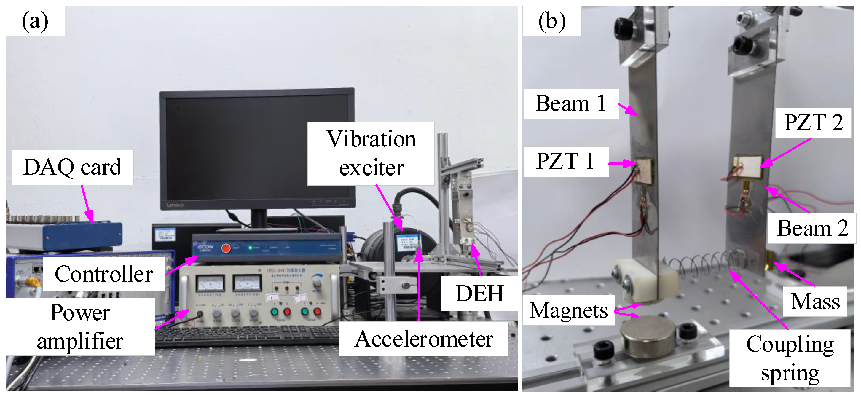
3.1. Experiment Setup

The experiment setup is depicted in Figure 2a. The fabricated device is mounted on an optical table and connected to an electrodynamic shaker (HEV−200, Nanjing Foneng Technology Industry Co., Ltd., Nanjing, China), which is driven by an amplifier (HEA−2000C) and governed by a controller (ECON VT−9008, ECON Technology Co., Ltd., Hangzhou, China). The acceleration amplitude and frequency range are determined by the controller. An accelerometer (DYTRAN 3097A2, Dytran Instruments, Inc., Chatsworth, Los Angeles County, California, USA) is mounted on the optical table and linked to the controller. A DAQ card (NI USB−6361, National Instruments, Austin, Texas, USA) is used to capture the output voltage on the piezoelectric elements. The experimental investigation was conducted on a vibration isolation optical platform, which can effectively damp the external disturbances. Each constant frequency is repeated at least three times, with variations in measured voltage amplitudes consistently maintained within ±3%, confirming high repeatability.
Figure 2b shows the device of the DEH. Magnet A is mounted on the end of Beam 1 using a resin clamp. Magnet B is placed under Magnet A. Beam 2’s tip−mass is brass, which cannot be affected by the magnetic fields. A piezoelectric patch is placed in the center of each beam, so as to prevent damage caused by large−amplitude oscillation. Material properties and geometric parameters of the DEH are detailed in Table 1. The values of equivalent mass, equivalent stiffness, equivalent damping, equivalent capacitance, and equivalent electromechanical coupling factor are obtained in the experiment [51]. The symbols and values of system parameters are listed in Table 2.

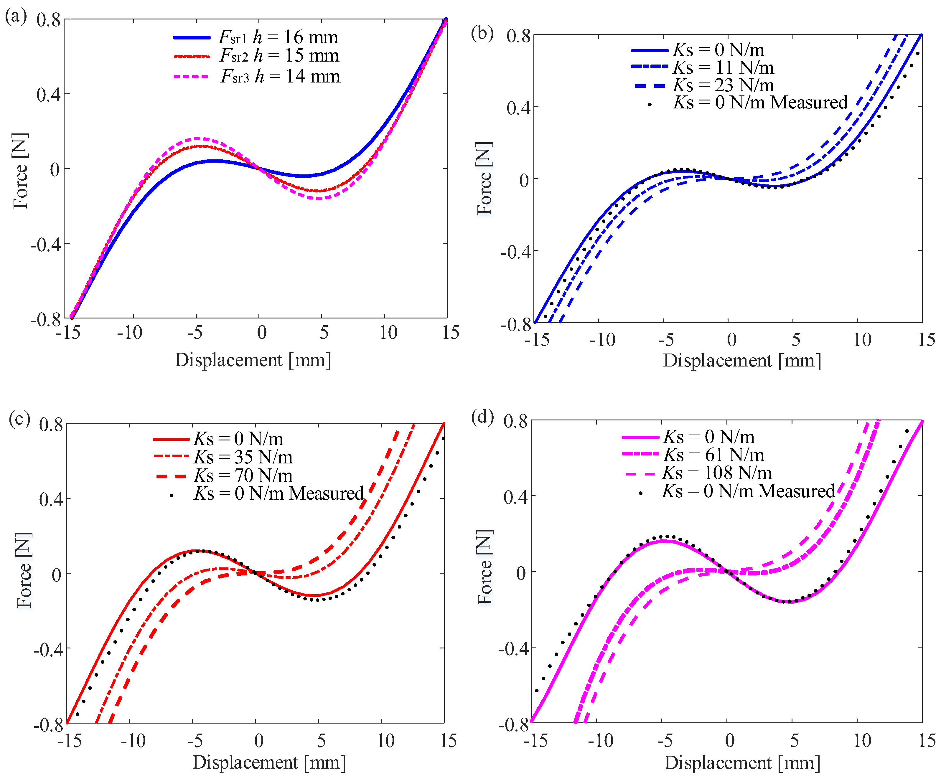
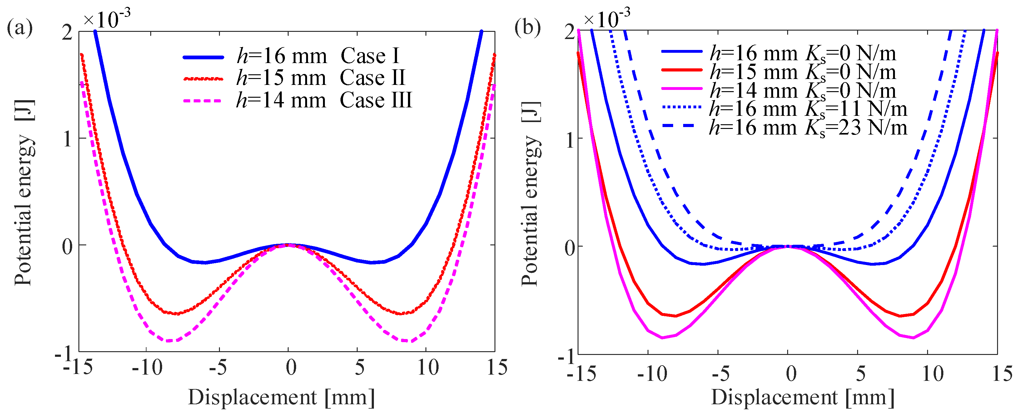
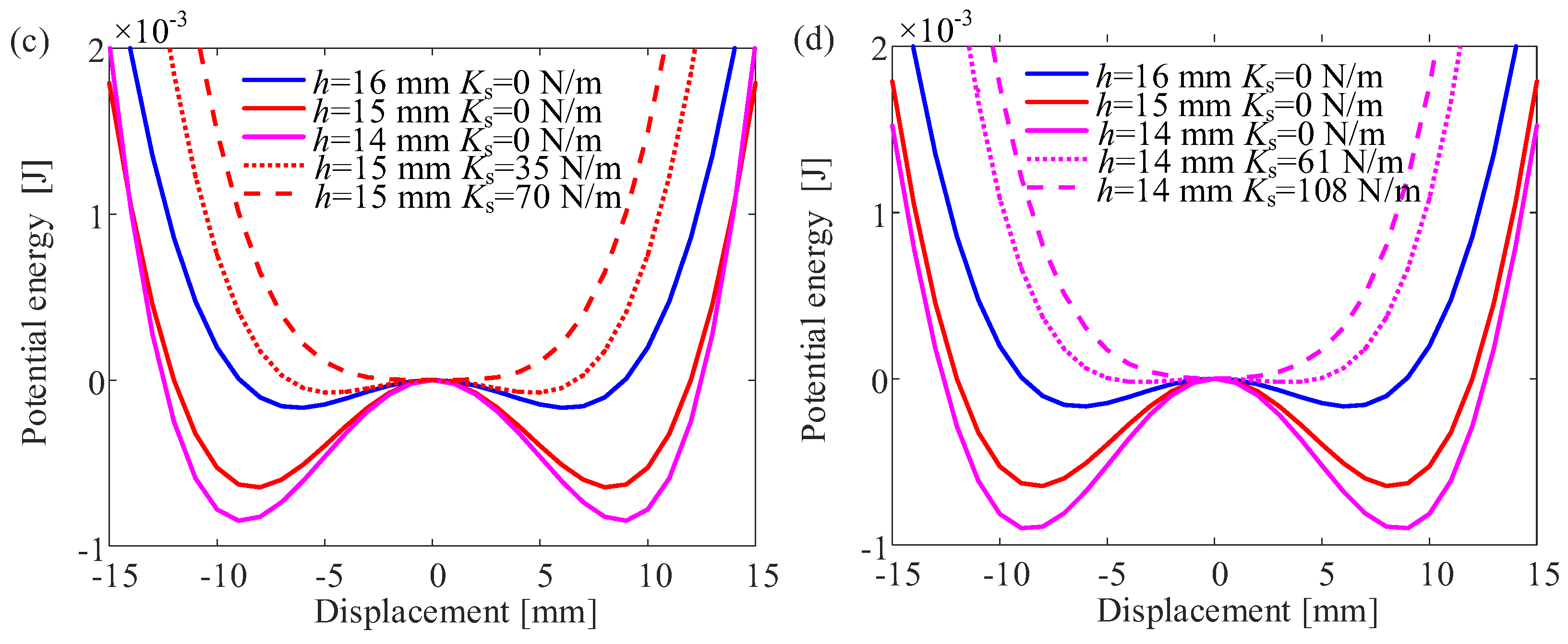
3.2. Nonlinear Restoring Forces and Potential Energy for Beam 1

Without the coupling spring (Ks = 0 N/m), the static nonlinear restoring force for Beam 1 can be determined by using the electronic dynamometer (HANDPI HP−10, HANDPI Instruments Co., Ltd., Wenzhou, China) [51]. It is worth noting that the distance between Beam 1 and Beam 2 was kept fixed (d1 = 38 mm), and the distance between the two magnets (h) was changed to achieve different restoring forces and potential wells. The nonlinear restoring force and displacement of Beam 1 obtained from the experiment were fitted using MATLAB(R2020a)’s Curve Fitting toolbox. In theory, the Fsr should be symmetric, and the fitted higher−order polynomial retains only odd−degree terms. When h is 16 mm, the corresponding polynomial equation for nonlinear restoring force of Beam 1 (Fsr1) can be written as follows:
F sr 1 = 17.55 x + 4.761 × 10 5 x 3 6.993 × 10 8 x 5
When h = 15 mm, the Fsr2 will be as follows:
F sr 2 = 39.57 x + 6.5 × 10 5 x 3 1.047 × 10 9 x 5
When h is reduced to 14 mm, the Fsr3 will be as follows:
F sr 3 = 51.68 x + 8.1045 × 10 5 x 3 1.539 × 10 9 x 5
Figure 3 and Figure 4 show the varying nonlinear restoring force and potential energy of Beam 1 with various coupling spring stiffness under different magnet distances. For the DEH, both the potential well depth and width of two symmetric potential wells become larger with the decrease in the value of h. As h = 16 mm (Case I), the initial potential well depth is measured to be 0.17 mJ; when the height is reduced to 15 mm (Case II), the initial potential well depth increases to 0.64 mJ, and upon further reduction to 14 mm (Case III), it is 0.9 mJ. These are shown in Table 3. When there is no coupling spring (Ks = 0 N/m), Beam 1 is characterized by the presence of two stable equilibrium positions. As the coupling spring stiffness increases, there is a corresponding reduction in the potential barrier. For achieving the state of transitioning from a bistable to a monostable regime, Ks will be 23 N/m, 70 N/m, 108 N/m for various initial potential well depths (0.17 mJ, 0.64 mJ, 0.9 mJ), respectively, which can be represented by (Ks)monostable−to−bistable.

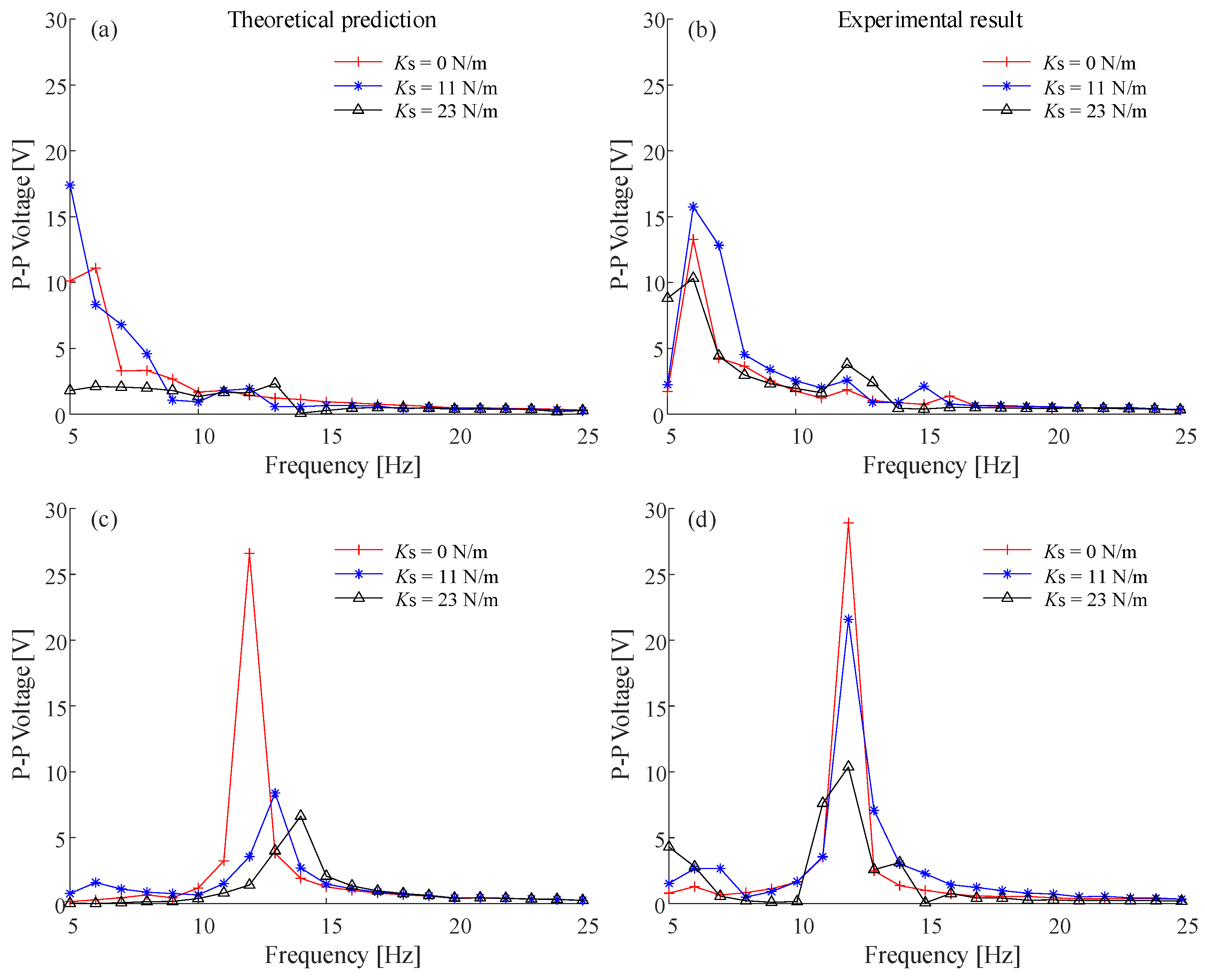
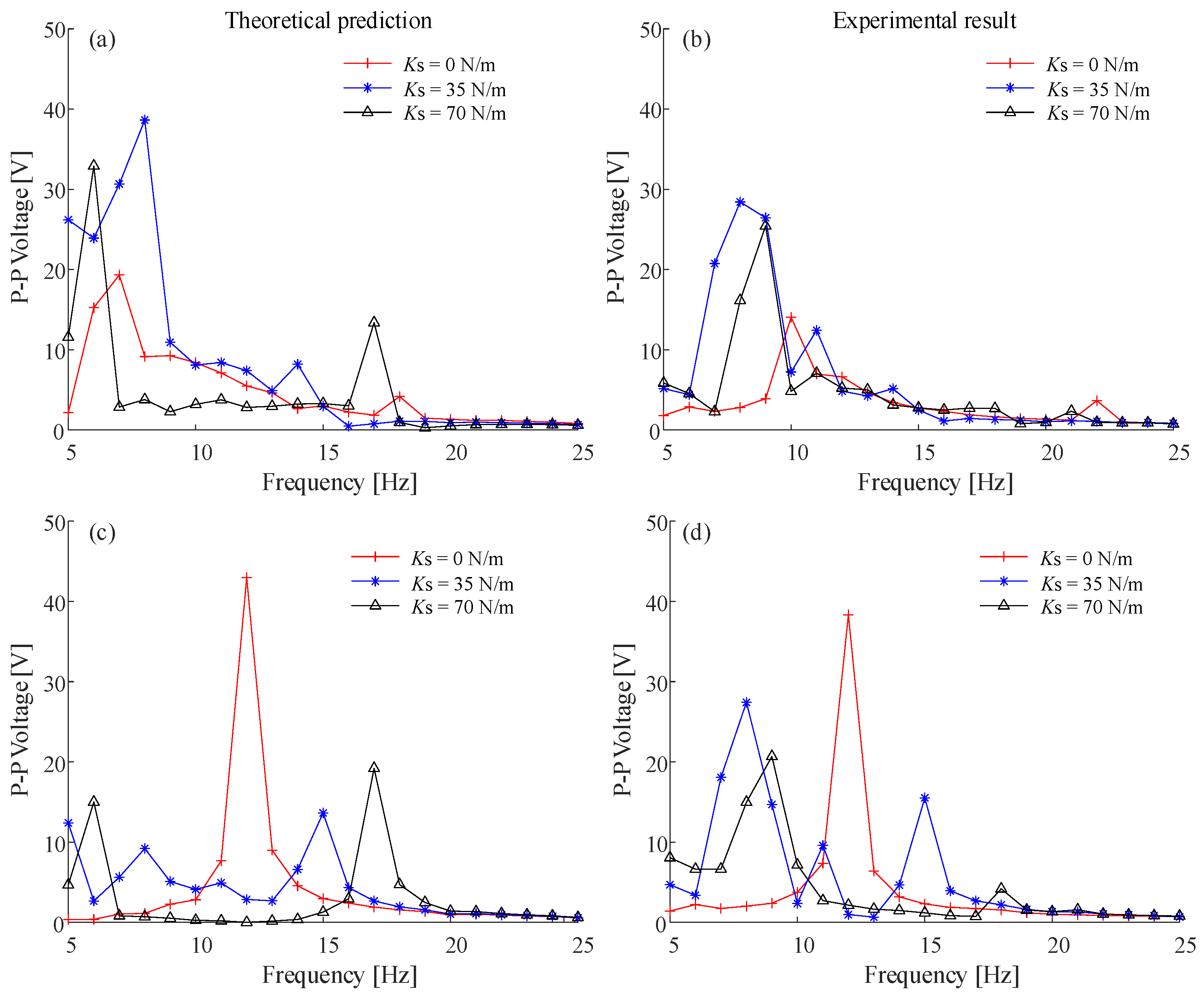
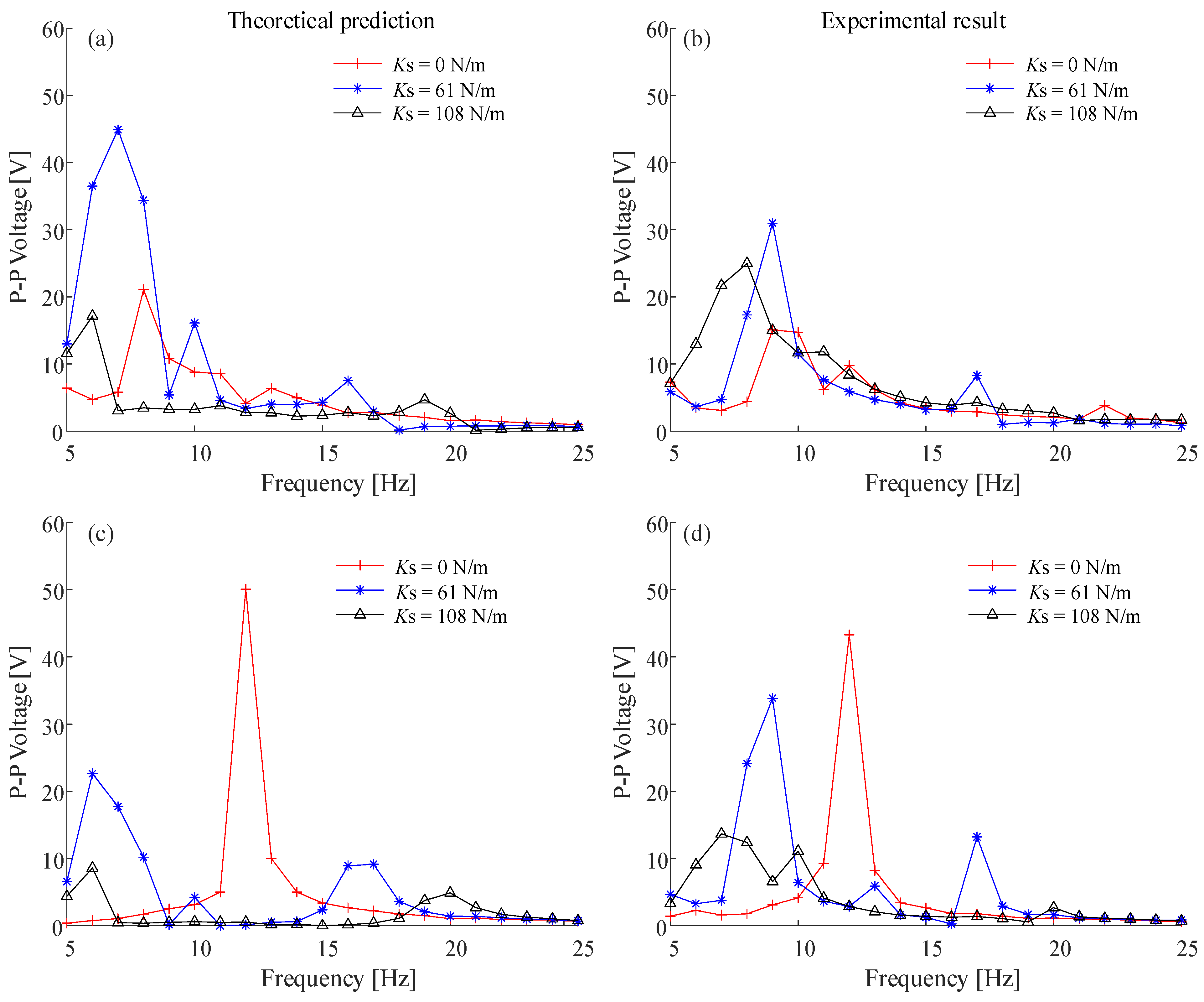
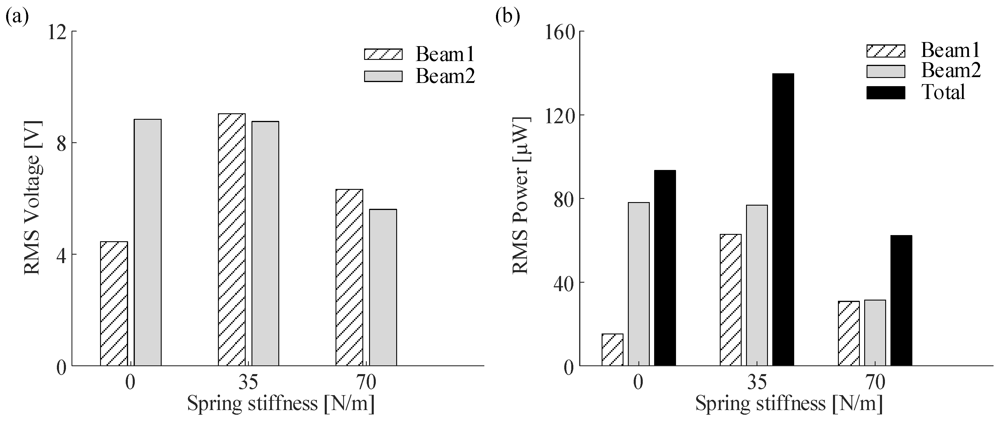
4. Influence of Varying Potential Well Depths on the DEH

In order to analyze the influence of various potential well depths on the performance of the DEH, simulation and experiment were executed under constant frequency excitation.

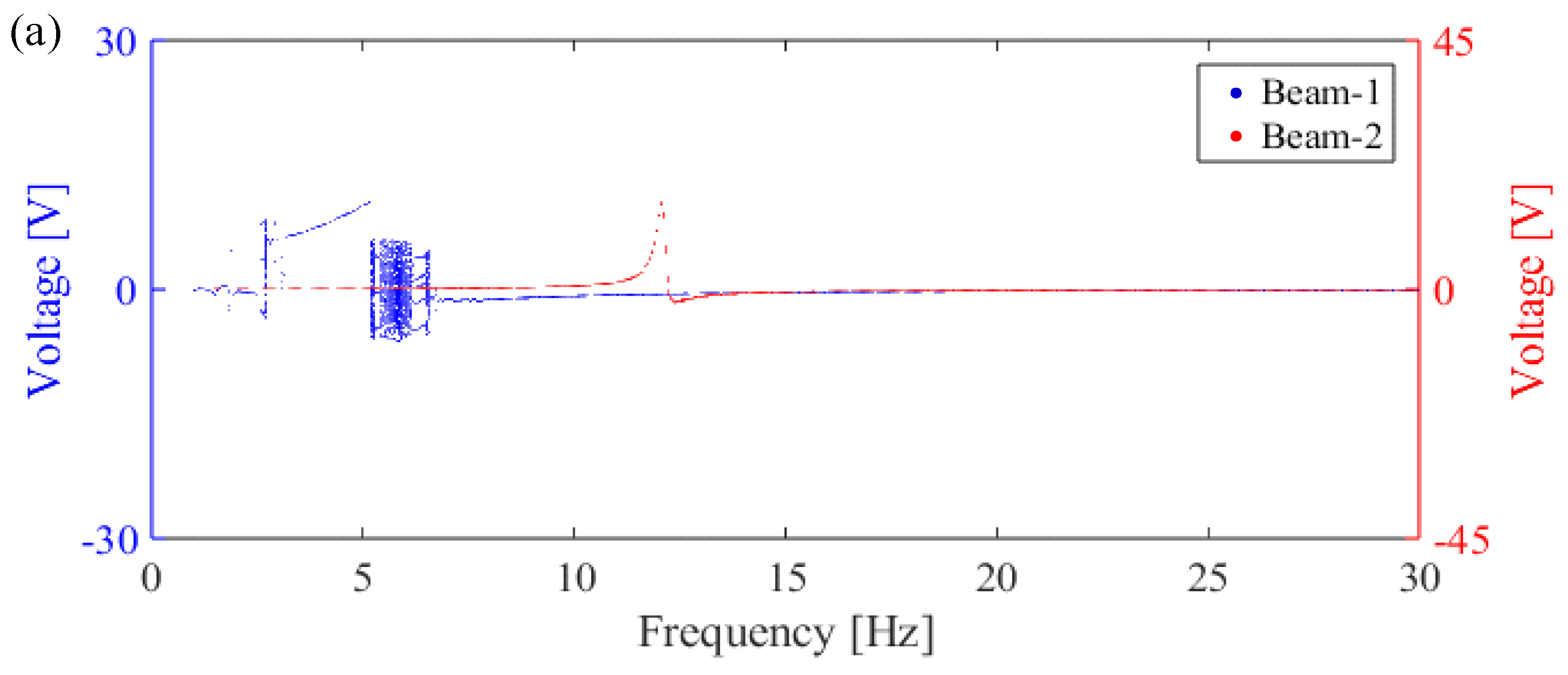
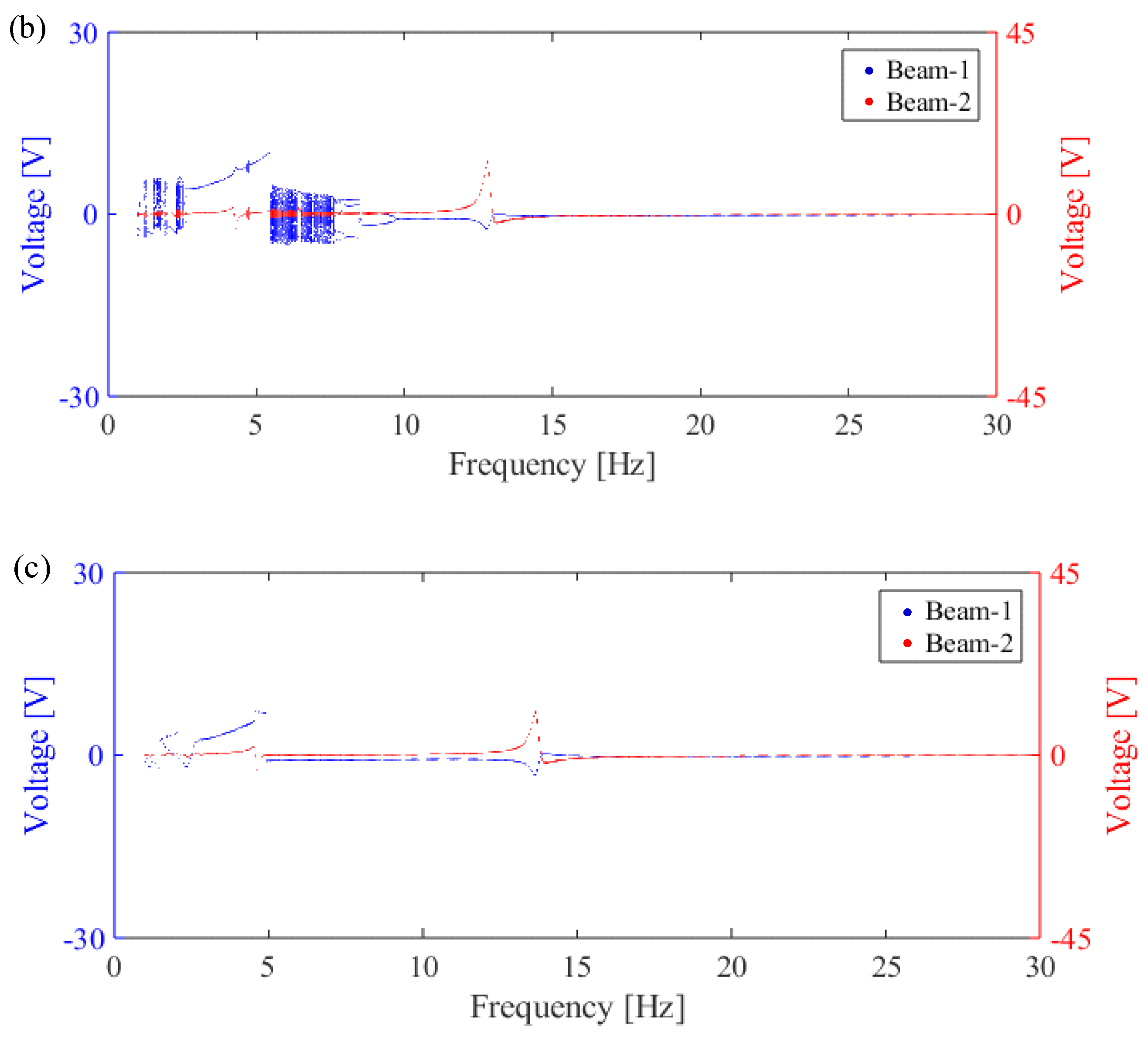
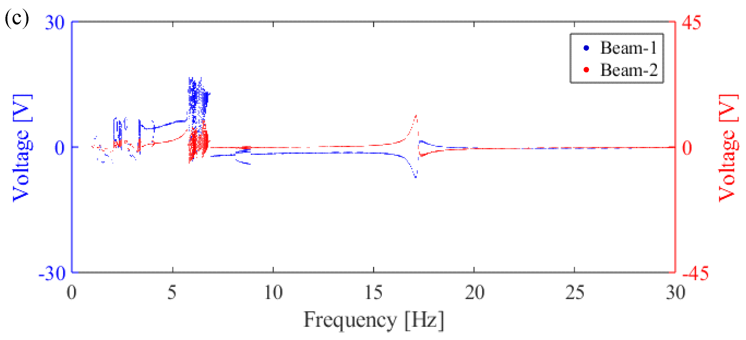
4.1. Numerical Simulation Under Constant Frequency Excitation

In this section, numerical simulations are performed to investigate the response of the DEH under constant frequency excitation. Bifurcation diagrams illustrating open circuit voltage and vibration frequency with various potential well depths are featured in Figure 5, Figure 6 and Figure 7. By applying up−sweep frequency excitation to the DEH, the acceleration threshold of Beam 1 which can maintain high−energy inter−well oscillation can be determined for various potential wells (Case I, Case II, and Case III). The excitation accelerations are 1.9 m/s2 (Case I), 4.5 m/s2 (Case II), and 4.8 m/s2 (Case III), respectively, which are used as the excitation intensity of constant frequency excitation for three cases. The excitation frequency ranges from 1 Hz to 30 Hz with the step size of 0.05 Hz.
As shown in Figure 5a, Figure 6a and Figure 7a, Beam 1 experiences intra−well oscillation, large−amplitude periodic oscillation, chaotic oscillation, and a return to intra−well oscillation. In contrast, the LEH (Beam 2) displays a distinct monostable response and attains its maximum output voltage at a frequency of 12.1 Hz.
When the spring stiffness is half of the (Ks)monostable−to−bistable, the output voltage of Beam 1 and Beam 2 is presented in Figure 5b, Figure 6b and Figure 7b. As shown in Figure 5b, it initially enters a regime of chaotic motion, followed by large−amplitude periodic or quasi−periodic oscillations within the frequency range of 2.7 to 5.5 Hz, and subsequently reverts to a state of chaotic motion between 5.5 and 7.6 Hz. In addition, when the excitation frequency is higher than 7.6 Hz, the bifurcation diagram has some inter−well or intra−well periodic motion branches. Similarly, as shown in Figure 6b and Figure 7b, Beam 1 undergoes chaotic motion, large−amplitude periodic or quasi−periodic motion (4.2–8.1 Hz, 4.45–8.5 Hz), and chaotic motion (8.1–11.3 Hz, 8.5–11.25 Hz).
At the coupling spring stiffness (Ks)monostable−to−bistable, the output voltages for both Beam 1 and Beam 2 are depicted in Figure 5c, Figure 6c and Figure 7c. Within the 2.55–4.7 Hz, 3.6–6.65 Hz, and 4.05–6.95 Hz frequency range, Beam 1 and Beam 2 achieve large−amplitude periodic oscillations. As the stiffness of the coupling spring increases, there is a consequent increase in the kinetic energy transfer from Beam 1 to Beam 2. This transfer results in an output voltage decrease in Beam 1, while leading to an enhancement in the output voltage of Beam 2.
Briefly, numerical results indicate that the traditional BEH and LEH (Ks = 0 N/m) have higher output response and broader operating bandwidth at a deep potential well depth under constant frequency excitation. In addition, the traditional BEH and LEH (Ks = 0 N/m) can achieve better performance in low−frequency vibration when the potential well depth is shallow. However, when the coupling spring is introduced, whether initial potential well depth is shallow or not, the frequency response of the DEH will shift to the low−frequency range. In addition, voltage output and operation bandwidth of the DEH can both be enhanced.

4.2. Experimental Verification of Constant Frequency Excitation

Figure 8, Figure 9 and Figure 10 illustrate the relationship between the excitation frequency and the peak–peak voltage of Beam 1 and Beam 2 under various coupling spring stiffness (Ks).
For traditional BEH and LEH (Ks = 0 N/m), the peak−to−peak voltage of Beam 1 is 13.3 V when the excitation frequency is 6 Hz in Case I. Beam 2 has a peak−to−peak voltage of 28.9 V with a frequency of 12 Hz. In Case II, Beam 1’s peak−to−peak voltage decreases to 14.1 V at 10 Hz, while Beam 2’ s peak−to−peak voltage increases to 38.3 V. In Case III, the peak−to−peak voltage of Beam 1 rises to 15.1 V at 9 Hz and Beam 2 reaches 43.3 V.
The experimental data reveal that Beam 1 has two voltage peaks when Ks is half of (Ks)monostable−to−bistable (Ks = 11 N/m, Ks = 35 N/m, Ks = 61 N/m). These peaks are 15.7 V at a frequency of 6 Hz and 2.6 V at 12 Hz in Case I, respectively. In Case II, the voltage peaks rise to 28.4 V at 8 Hz and 12.4 V at 11 Hz, respectively. Meanwhile, Beam 1 results in peaks of 31 V at 9 Hz and 8.3 V at 17 Hz in Case III. When the coupling spring stiffness is less than the monostable−to−bistable stiffness of the system, the increase in the coupling stiffness will cause the resonance frequency of the system to decrease (shift to the left), which agrees with the numerical results.
However, as the coupling stiffness reaches the (Ks)monostable−to−bistable (Ks = 23 N/m, Ks = 70 N/m, Ks = 108 N/m), the constraints imposed by the spring lead to a reduction in the vibration amplitudes of both Beam 1 and Beam 2.
Figure 11, Figure 12 and Figure 13 are theoretical and experimental comparisons of root mean square (RMS) voltage and RMS power of the DEH with different coupling spring stiffness at various potential well depths. For Case I and Ks = 0 N/m (1.9 m/s2 excitation level), the RMS voltages of two beams are 3.35 V and 6.45 V, respectively. When the coupling spring is introduced, the RMS voltages of Beam 1 will rise to 3.89 V (Ks = 11 N/m) and 4.08 V (Ks = 23 N/m). In Case II and the excitation level of 4.5 m/s2, Beam 1 achieves the RMS voltages of 4.45 V (Ks = 0 N/m), 9.04 V (Ks = 35 N/m), and 6.33 V (Ks = 70 N/m). The RMS voltage of Beam 2 is 8.84 V at Ks = 0 N/m. As shown in Figure 13a, when the excitation level is raised to 4.8 m/s2 for Case III, the RMS voltages of Beam 1 and Beam 2 are 6.22 V and 10.04 V (Ks = 0 N/m), respectively. When the coupling spring is applied, the RMS voltages of Beam 1 will be 8.29 V (Ks = 61 N/m) and 10.48 V (Ks = 108 N/m).
When Ks is half of (Ks)monostable−to−bistable, the total RMS power generated by the DEH increases by 6.4% (from 50.76 μW to 54.01 μW) at Case I, 49.6% (from 93.38 μW to 139.68 μW) at Case II, and 16.4% (from 130.49 μW to 151.85 μW) at Case III, compared to the traditional BEH and LEH (Ks = 0 N/m). When Ks is (Ks)monostable−to−bistable, the total RMS powers of the DEH are 19.43 μW (Case I), 62.3 μW (Case II), and 123.27 μW (Case III). Compared to the traditional BEH and LEH, the RMS power of the DEH is reduced, since the DEH (Ks = (Ks)monostable−to−bistable)) has changed into a linear system.
Figure 14 shows the relationship between the output power of Beam 1 and Beam 2 under different coupling spring stiffness and excitation frequencies in Case II. The output power is calculated by P = V2/R. The results are consistent with the previous discussion of system response. The Sobol method is used to analyze the sensitivity of the system, and the influence of the coupling spring stiffness on the output voltage is explored. In the case of single parameters, the first−order Sobol index is equal to the proportion of the main effect to the total variance [52]. In order to ensure the accuracy of the results, the first−order Sobol index is estimated by cubic polynomial regression. For Case II, the coupling spring stiffness KS sampling range is set to 10–110 N/m, and 100 sample points are generated using Sobol sequence. Figure 15 shows the output voltage of Beam 1 and Beam 2 under constant frequency excitation of A = 4.5 m/s2 and f = 8 Hz using sensitivity analysis. The independent contribution of KS to the output voltage of Beam 1 is about 22.65% (0.2265), and the independent influence of KS on output voltage of Beam 2 is only 10.95% (0.1095). The results show that coupling spring stiffness KS has obvious single−parameter control ability on the output voltage of Beam 1 but has a weak effect on the output voltage of Beam 2. It is worth noting that the variation in voltage is more dominated by other parameters, such as the electromechanical coupling coefficient θ.
On the other hand, the operating bandwidth at various potential well depths is shown in Figure 16. Here, 30%−Hmax is defined as the operational bandwidth of monostable motion [53]. In the 30%−Hmax range, the voltage amplitude of the harvester always exceeds 30% of its maximum relative voltage amplitude. The frequency range from the jump−up frequency to the jump−down frequency is calculated as the operational bandwidth of bistable oscillation. In Case I, the total operating bandwidth of the DEH is 5 Hz when Ks = 11 N/m. When Ks is increased to 23 N/m, the working bandwidth of the DEH extends to 7 Hz. In Case II and Ks = 35 N/m, Beam 1 follows a high−energy inter−well oscillation from 6 to 10 Hz, and the operation bandwidth of the DEH reaches 9 Hz. When Ks = 70 N/m, the DEH yields a total operating bandwidth of 9 Hz. In Case III, the total operating bandwidth of the DEH achieves 9 Hz at Ks = 61 N/m and extends to 13 Hz at Ks = 108 N/m. Finally, it can be concluded that, regardless of the potential well depth, the optimal operating bandwidth of the DEH can be obtained when Ks is (Ks)monostable−to−bistable. Compared with the traditional BEH and LEH (Ks = 0 N/m), the operating bandwidths of the DEH (Ks = (Ks)monostable−to−bistable)) are increased by 133.3%, 80%, and 85.7%, respectively.

5. Conclusions

This paper investigates the influence of varying potential well depths on the performance of dual−coupled beam energy harvester (DEH). At first, three different potential well depths were established with the different polynomial coefficients of nonlinear restoring force and analyzed in simulation. Numerical results revealed that whether initial potential well depth is shallow or not, the optimal power output can be attained when the stiffness of the couple spring is half of the monostable−to−bistable coupling spring stiffness. This was also validated by an experiment. Under constant frequency excitation, the optimal stiffness of coupling spring is 11 N/m for 0.17 mJ potential well depth (Case I), 35 N/m for 0.64 mJ potential well depth (Case II), and 61 N/m for 0.9 mJ potential well depth (Case III), respectively. In such a coupling spring configuration, the total RMS power is improved by 6.4% (from 50.76 μW to 54.01 μW) at Case I, 49.6% (from 93.38 μW to 139.68 μW) at Case II, and 16.4% (from 130.49 μW to 151.85 μW) at Case III, compared to the traditional BEH and LEH (Ks = 0 N/m). On the other hand, the DEH achieves its widest operating bandwidth when the coupling spring stiffness is near the monostable−to−bistable transition region. Compared with the traditional BEH and LEH, the operating bandwidth of the DEH is increased by 133.3%, 80%, and 85.7%, respectively. It is worth noting that the performance of the DEH with different potential well depths is studied by introducing coupling springs with different stiffnesses to alter potential well depths and widths. Consequently, the optimal coupling spring stiffness value presented in the conclusion serves as a reference for a broader range of DEH designs.
Summarily, theoretical and experimental results show the traditional BEH and LEH (Ks = 0 N/m) have higher output voltage and broader operating bandwidth at a deep potential well depth under constant frequency excitation. In addition, the traditional BEH and LEH (Ks = 0 N/m) can achieve better performance in low−frequency vibration when the potential well depth is shallow. However, when the coupling spring is introduced, whether initial potential well depth is shallow or not, the frequency response of the DEH will shift to the low−frequency range, which will definitely benefit the low−frequency vibration energy harvesting. In addition, RMS power and operation bandwidth of the DEH can also be enhanced when optimal coupling spring stiffness is applied. Fatigue testing of the device will be performed in future works to systematically evaluate the long−term mechanical integrity and electrical stability of the DEH.

Author Contributions

Conceptualization, S.R.; Methodology, S.R.; Software, S.R. and L.T.; Validation, S.R.; Investigation, S.R.; Resources, H.S.; Writing—original draft, S.R.; Writing—review & editing, H.S.; Supervision, H.S. All authors have read and agreed to the published version of the manuscript.

Funding

This work was supported by National Natural Science Foundation of China (Grant Numbers 51975303). The authors have no relevant financial or non−financial interests to disclose.

Data Availability Statement

The datasets generated during and/or analyzed during the current study are available from the corresponding author on reasonable request.

Conflicts of Interest

The authors declare no conflict of interest.

References

  1. Lai, Z.; Xu, J.; Bowen, C.R.; Zhou, S. Self-powered and self-sensing devices based on human motion. Joule 2022, 6, 1501–1565. [Google Scholar] [CrossRef]
  2. Yang, Z.; Zhou, S.; Zu, J.; Inman, D. High-performance piezoelectric energy harvesters and their applications. Joule 2018, 2, 642–697. [Google Scholar] [CrossRef]
  3. Zhang, Y.; Cao, J.; Zhu, H.; Lei, Y. Design, modeling and experimental verification of circular Halbach electromagnetic energy harvesting from bearing motion. Energy Convers Manag. 2019, 180, 811–821. [Google Scholar] [CrossRef]
  4. Fan, K.; Hao, J.; Wang, C.; Zhang, C.; Wang, W.; Wang, F. An eccentric mass-based rotational energy harvester for capturing ultralow-frequency mechanical energy. Energy Convers Manag. 2021, 241, 114301. [Google Scholar] [CrossRef]
  5. Zhu, J.; Fan, K.; Wang, W.; Zhai, K.; Zhang, L.; Zhou, J.; Li, C.; Li, Y.; Li, J.; Liu, Y.; et al. A robust hybrid nanogenerator strategy achieved by regenerative motion transmission toward wind energy harvesting and self-powered sensing. Nano Energy 2025, 135, 110697. [Google Scholar] [CrossRef]
  6. Zhao, H.; Fan, K.; Zhao, S.; Wu, S.; Zhang, X.; Hou, Z. Lightweight energy harvesting backpack achieved with a slingshot-inspired flexible accelerator. Appl. Energy 2025, 379, 124993. [Google Scholar] [CrossRef]
  7. Zhang, H.; Zhou, S.; Zhang, J.; Ma, H.; Zhou, S. A sustainable and enhanced-performance vibration energy harvester for application on railway bridge: Design, modeling, and analysis. Mech. Syst. Signal Process. 2025, 225, 112279. [Google Scholar] [CrossRef]
  8. Li, Z.; Lyu, W.; Gong, C.; Zhou, S.; Li, C. Experimental investigation and dynamic analysis of a novel electromagnetic energy harvester based on airfoil flutter. Energy Convers. Manag. 2025, 326, 119471. [Google Scholar] [CrossRef]
  9. Li, Q.; He, L.; Lv, X.; Liu, Z.; Li, Z.; Fan, W. A piezoelectric energy harvester based on center of gravity shift. Appl. Energy 2025, 377, 124394. [Google Scholar] [CrossRef]
  10. Zhou, S.; Cao, J.; Erturk, A.; Lin, J. Enhanced broadband piezoelectric energy harvesting using rotatable magnets. Appl. Phys. Lett. 2013, 102, 173901. [Google Scholar] [CrossRef]
  11. Huguet, T.; Badel, A.; Lallart, M.; Druet, O. Drastic bandwidth enhancement of bistable energy harvesters: Study of subharmonic behaviors and their stability robustness. Appl. Energy 2018, 226, 607–617. [Google Scholar] [CrossRef]
  12. Fang, S.; Chen, K.; Xing, J.W. Liao. Tuned bistable nonlinear energy sink for simultaneously improved vibration suppression and energy harvesting. Int. J. Mech. Sci. 2021, 212, 106838. [Google Scholar] [CrossRef]
  13. Xue, H.; Hu, Y.; Wang, Q.M. Broadband piezoelectric energy harvesting devices using multiple bimorphs with different operating frequencies. IEEE Trans. Ultrason. Ferroelectr. Freq. Control. 2008, 55, 2104–2108. [Google Scholar] [CrossRef] [PubMed]
  14. Sun, R.; Li, Q.; Yao, J.; Scarpa, F.; Rossiter, J. Tunable, multi-modal, and multidirectional vibration energy harvester based on three-dimensional architected metastructures. Appl. Energy 2020, 264, 114615. [Google Scholar] [CrossRef]
  15. Dhote, S.; Yang, Z.; Zu, J. Modeling and experimental parametric study of a tri-leg compliant orthoplanar spring based multi-mode piezoelectric energy harvester. Mech. Syst. Signal Process. 2018, 98, 268–280. [Google Scholar] [CrossRef]
  16. Toyabur, R.M.; Salauddin, M.; Park, J.Y. Design and experiment of piezoelectric multimodal energy harvester for low frequency vibration. Ceram. Int. 2017, 43, S675–S681. [Google Scholar] [CrossRef]
  17. Challa, V.R.; Prasad, M.G.; Shi, Y.; Fisher, F.T. A vibration energy harvesting device with bidirectional resonance frequency tunability. Smart Mater. Struct. 2008, 17, 015035. [Google Scholar] [CrossRef]
  18. Podder, P.; Constantinou, P.; Mallick, D.; Amann, A.; Roy, S. Magnetic tuning of nonlinear MEMS electromagnetic vibration energy harvester. J. Microelectromech. Syst. 2017, 26, 539–549. [Google Scholar] [CrossRef]
  19. Wu, Y.; Li, S.; Fan, K.; Ji, H.; Qiu, J. Investigation of an ultra-low frequency piezoelectric energy harvester with high frequency up-conversion factor caused by internal resonance mechanism. Mech. Syst. Signal Process. 2022, 162, 108038. [Google Scholar] [CrossRef]
  20. Stanton, S.C.; McGehee, C.C.; Mann, B.P. Nonlinear dynamics for broadband energy harvesting: Investigation of a bistable piezoelectric inertial generator. Phys. D Nonlinear Phenom. 2010, 239, 640–653. [Google Scholar] [CrossRef]
  21. Liu, Q.; Qin, W.; Yang, Y.; Zhou, Z. Harvesting weak vibration energy by amplified inertial force and multi-stable buckling piezoelectric structure. Mech. Syst. Signal Process. 2023, 189, 110125. [Google Scholar] [CrossRef]
  22. Liu, Q.; Qin, W.; Yang, T.; Deng, W.; Zhou, Z. Harvesting weak vibration energy by amplified inertial force and super-harmonic vibration. Energy 2023, 263, 125948. [Google Scholar] [CrossRef]
  23. Ma, X.; Ma, H.; Zhou, S. Nonlinear analysis and response identification of tristable energy harvesters under wind and base excitations. Int. J. Non-Linear Mech. 2025, 173, 105052. [Google Scholar] [CrossRef]
  24. Fang, S.; Chen, K.; Lai, Z.; Zhou, S.; Liao, W. Snap-through energy harvester with buckled mechanism and hierarchical auxetic structures for ultra-low-frequency rotational excitations. Appl. Phys. Lett. 2023, 122, 93901. [Google Scholar] [CrossRef]
  25. Tian, L.; Shen, H.; Yang, Q.; Song, R.; Bian, Y. A novel outer-inner magnetic two degree-of-freedom piezoelectric energy harvester. Energy Convers. Manag. 2023, 283, 116920. [Google Scholar] [CrossRef]
  26. Chen, K.; Gao, F.; Liu, Z.; Liao, W. A nonlinear M-shaped tri-directional piezoelectric energy harvester. Smart Mater. Struct. 2021, 30, 045017. [Google Scholar] [CrossRef]
  27. Xing, J.; Fang, S.; Fu, X.; Liao, W.H. A rotational hybrid energy harvester utilizing bistability for low-frequency applications: Modelling and experimental validation. Int. J. Mech. Sci. 2022, 222, 107235. [Google Scholar] [CrossRef]
  28. Xiang, X.; Chen, K.; Yang, Q.; Shen, H. Reversible nonlinear energy harvester tuned by titling angle or clamping distance. Sens. Actuators A Phys. 2024, 366, 115009. [Google Scholar] [CrossRef]
  29. Chen, J.; Bao, B.; Liu, J.; Wu, Y.; Wang, Q. Piezoelectric energy harvester featuring a magnetic chaotic pendulum. Energy Convers. Manag. 2022, 269, 116155. [Google Scholar] [CrossRef]
  30. Li, H.; Qin, W. Dynamics and coherence resonance of a laminated piezoelectric beam for energy harvesting. Nonlinear Dyn. 2015, 81, 1751–1757. [Google Scholar] [CrossRef]
  31. Zhang, H.; Ma, T. Adaptive energy harvesting from low-level ambient vibrations. Appl. Mater. Today 2023, 34, 101911. [Google Scholar] [CrossRef]
  32. Vocca, H.; Neri, I.; Travasso, F.; Gammaitoni, L. Kinetic energy harvesting with bistable oscillators. Appl. Energy 2012, 97, 771–776. [Google Scholar] [CrossRef]
  33. Wang, H.; Zhao, Q.; Song, R.; Guo, J.; Chang, W.; Yang, X.; Zhang, L. Design and performance study of low frequency magnetic coupling bistable piezoelectric and electromagnetic energy harvester. Energy 2025, 320, 135178. [Google Scholar] [CrossRef]
  34. Ma, X.; Litak, G.; Zhou, S. Using 0–1 test to diagnose periodic and chaotic motions of nonlinear vortex-induced vibration energy harvesters. Chaos Solitons Fractals 2025, 192, 116036. [Google Scholar] [CrossRef]
  35. Harne, R.L.; Wang, K.W. A review of the recent research on vibration energy harvesting via bistable systems. Smart Mater. Struct. 2013, 22, 23001. [Google Scholar] [CrossRef]
  36. Deng, H.; Wang, Z.; Du, Y.; Zhang, J.; Ma, M.; Zhong, X. A seesaw-type approach for enhancing nonlinear energy harvesting. Appl. Phys. Lett. 2018, 112, 213902. [Google Scholar] [CrossRef]
  37. Zhou, S.; Cao, J.; Inman, D.J.; Lin, J.; Liu, S.; Wang, Z. Broadband tristable energy harvester: Modeling and experiment verification. Appl. Energy 2014, 133, 33–39. [Google Scholar] [CrossRef]
  38. Zhou, S.; Zuo, L. Nonlinear dynamic analysis of asymmetric tristable energy harvesters for enhanced energy harvesting. Commun. Nonlinear Sci. Numer. Simul. 2018, 61, 271–284. [Google Scholar] [CrossRef]
  39. Wang, C.; Zhang, Q.; Wang, W.; Feng, J. A low-frequency, wideband quad-stable energy harvester using combined nonlinearity and frequency up-conversion by cantilever-surface contact. Mech. Syst. Signal Process. 2018, 112, 305–318. [Google Scholar] [CrossRef]
  40. Lan, C.; Qin, W. Enhancing ability of harvesting energy from random vibration by decreasing the potential barrier of bistable harvester. Mech. Syst. Signal Process. 2017, 85, 71–81. [Google Scholar] [CrossRef]
  41. Mei, X.; Zhou, S.; Yang, Z.; Kaizuka, T.; Nakano, K. Enhancing energy harvesting in low-frequency rotational motion by a quad-stable energy harvester with time-varying potential wells. Mech. Syst. Signal Process. 2021, 148, 107167. [Google Scholar] [CrossRef]
  42. Ma, X.; Li, H.; Zhou, S.; Yang, Z.; Litak, G. Characterizing nonlinear characteristics of asymmetric tristable energy harvesters. Mech. Syst. Signal Process. 2022, 168, 108612. [Google Scholar] [CrossRef]
  43. Xu, H.; Zhou, S. Theoretical analysis and potential engineering application of an energy harvester. Int. J. Mech. Sci. 2024, 275, 109284. [Google Scholar] [CrossRef]
  44. Margielewicz, J.; Gąska, D.; Caban, J.; Litak, G.; Dudziak, A.; Ma, X.; Zhou, S. Double-Versus Triple-Potential Well Energy Harvesters: Dynamics and Power Output. Sensors 2023, 23, 2185. [Google Scholar] [CrossRef]
  45. He, Q.; Daqaq, M.F. Influence of potential function asymmetries on the performance of nonlinear energy harvesters under white noise. J. Sound Vib. 2014, 333, 3479–3489. [Google Scholar] [CrossRef]
  46. Erturk, A.; Inman, D.J. Broadband piezoelectric power generation on high-energy orbits of the bistable Duffing oscillator with electromechanical coupling. J. Sound Vib. 2011, 330, 2339–2353. [Google Scholar] [CrossRef]
  47. Fang, S.; Fu, X.; Liao, W. Modeling and experimental validation on the interference of mechanical plucking energy harvesting. Mech. Syst. Signal Process. 2019, 134, 106317. [Google Scholar] [CrossRef]
  48. Lan, C.; Qin, W. Vibration energy harvesting from a piezo electric bistable system with two symmetric stops. Acta Phys. Sin. 2015, 64, 210501. [Google Scholar] [CrossRef]
  49. Fan, Y.; Niu, M.; Ghayesh, M.H.; Amabili, M.; Chen, L. Nonlinear vibration energy harvesting via parametric excitation: Snap-through with time-varying potential wells. Mech. Syst. Signal Process. 2024, 220, 111625. [Google Scholar] [CrossRef]
  50. Tang, L.; Yang, Y.; Soh, C.K. Improving functionality of vibration energy harvesters using magnets. J. Intell. Mater. Syst. Struct. 2012, 23, 1433–1449. [Google Scholar] [CrossRef]
  51. Chen, K.; Zhang, X.; Xiang, X.; Shen, H.; Yang, Q.; Wang, J.; Litak, G. High performance piezoelectric energy harvester with dual-coupling beams and bistable configurations. J. Sound Vib. 2023, 561, 117822. [Google Scholar] [CrossRef]
  52. Sobol, I.M. Global sensitivity indices for nonlinear mathematical models and their Monte Carlo estimates. Math. Comput. Simul. 2001, 55, 271–280. [Google Scholar] [CrossRef]
  53. Liang, H.; Hao, G.; Olszewski, O.Z.; Pakrashi, V. Ultra-low wide bandwidth vibrational energy harvesting using a statically balanced compliant mechanism. Int. J. Mech. Sci. 2022, 219, 107130. [Google Scholar] [CrossRef]
Figure 1. (a) Schematic of the proposed DEH; (b) static state of the DEH (Fb(t) = 0); (c) motion state of the DEH (Fb(t) > 0).
Energies 18 01984 g001
Figure 2. (a) Experiment setup; (b) detailed view of the DEH.
Energies 18 01984 g002
Figure 3. The nonlinear restoring force of Beam 1 with various coupling spring stiffnesses at differ−ent magnet distances: (a) the static nonlinear restoring force (Ks = 0 N/m); (b) h = 16 mm; (c) h = 15 mm; (d) h = 14 mm.
Energies 18 01984 g003
Figure 4. The potential energy of Beam 1 with various coupling spring stiffnesses at different mag−net distances: (a) potential energy without coupling spring; (b) h = 16 mm; (c) h = 15 mm; (d) h = 14 mm.
Energies 18 01984 g004aEnergies 18 01984 g004b
Figure 5. Bifurcation diagram of the DEH at Case I (A = 1.9 m/s2): (a) 0 N/m; (b) 11 N/m; (c) 23 N/m.
Energies 18 01984 g005aEnergies 18 01984 g005b
Figure 6. Bifurcation diagram of the DEH at Case II (A = 4.5 m/s2): (a) 0 N/m; (b) 35 N/m; (c) 70 N/m.
Energies 18 01984 g006aEnergies 18 01984 g006b
Figure 7. Bifurcation diagram of the DEH at Case III (A = 4.8 m/s2): (a) 0 N/m; (b) 61 N/m; (c) 108 N/m.
Energies 18 01984 g007
Figure 8. Peak–peak voltage of the DEH under constant frequency excitation at Case I (A = 1.9 m/s2): (a,b) Beam 1; (c,d) Beam 2.
Energies 18 01984 g008
Figure 9. Peak–peak voltage of the DEH under constant frequency excitation at Case II (A = 4.5 m/s2): (a,b) Beam 1; (c,d) Beam 2.
Energies 18 01984 g009
Figure 10. Peak–peak voltage of the DEH under constant frequency excitation at Case III (A = 4.8 m/s2): (a,b) Beam 1; (c,d) Beam 2.
Energies 18 01984 g010
Figure 11. RMS voltage and RMS power of the DEH with different coupling spring stiffness under constant frequency excitation (Case I): (a) RMS voltage; (b) RMS power.
Energies 18 01984 g011
Figure 12. RMS voltage and RMS power of the DEH with different coupling spring stiffness under constant frequency excitation (Case II): (a) RMS voltage; (b) RMS power.
Energies 18 01984 g012
Figure 13. RMS voltage and RMS power of the DEH with different coupling spring stiffness under constant frequency excitation (Case III): (a) RMS voltage; (b) RMS power.
Energies 18 01984 g013
Figure 14. The relationship between the theoretical output power of Case II and the coupling spring stiffness and frequency: (a,b) Beam 1; (c,d) Beam 2.
Energies 18 01984 g014
Figure 15. Sobol first−order index of the effect of coupling spring stiffness on output voltage.
Energies 18 01984 g015
Figure 16. Operating bandwidth of the DEH with different coupling spring stiffness at various potential well depths.
Energies 18 01984 g016
Table 1. Material and geometry of the DEH.
DescriptionMaterialValue (mm)
Beam 1, Beam 2Stainless steel (Jiangsu Naite Stainless Steel Co., Ltd., Nantong, China)100 × 30 × 0.4
Piezo elementPZT−5H (Baoding Hongsheng Acoustic Electronic Equipment Co., Ltd., Baoding, China)20 × 10 × 0.5
SpringStainless steel (Ningde Li Spring Manufacturing Company, Dongguan, China)Ф10 × 31
Magnet A, Magnet BNdFeB (Shanghai Tianyu Magnetic Material Company, Shanghai, China)Ф15 × 5, Ф25 × 10
Tip−massBrass (Biling Hardware products Co., Ltd., Changsha, China)15 × 12 × 10
Table 2. Simulation parameters of the DEH.
DescriptionSymbolValue
Equivalent massM1, M218.9, 16.6 (g)
Equivalent dampingC1, C26.48 × 10−2 (Ns/m)
2.4 × 10⁻² (Ns/m)
Equivalent stiffnessK1, K2104, 96 (N/m)
Equivalent capacitanceCp1, Cp212.2, 11.5 (nF)
Load resistanceR1, R21.3, 1 (MΩ)
Equivalent electromechanical
coupling coefficient
θ1, θ22.76 × 10⁻⁵ (N/V)
1.8 × 10⁻⁵ (N/V)
Table 3. Potential well depth with different coupling spring stiffness.
Potential Well DepthCase ICase IICase III
Initial depth (mJ)0.17 (Ks = 0 N/m)0.64 (Ks = 0 N/m)0.9 (Ks = 0 N/m)
Depth 1 (mJ)0.03 (Ks = 11 N/m)0.075 (Ks = 35 N/m)0.02 (Ks = 61 N/m)
Depth 2 (mJ)0 (Ks = 23 N/m)0 (Ks = 70 N/m)0 (Ks = 108 N/m)
Disclaimer/Publisher’s Note: The statements, opinions and data contained in all publications are solely those of the individual author(s) and contributor(s) and not of MDPI and/or the editor(s). MDPI and/or the editor(s) disclaim responsibility for any injury to people or property resulting from any ideas, methods, instructions or products referred to in the content.

