Article

Achieving NOx Emissions with Zero-Impact on Air Quality from Diesel Light-Duty Commercial Vehicles

Chair of Thermodynamics of Mobile Energy Conversion Systems, RWTH Aachen University, 52062 Aachen, Germany
*
Author to whom correspondence should be addressed.
Energies 2025, 18(8), 1882; https://doi.org/10.3390/en18081882
Submission received: 11 February 2025 / Revised: 21 March 2025 / Accepted: 31 March 2025 / Published: 8 April 2025
(This article belongs to the Special Issue Emission Control Technology in Internal Combustion Engines)

Abstract

:
Many cities are still struggling to comply with current air quality regulations. Road transport is usually a significant source of NOx emissions, especially in urban areas. Therefore, NOx from road vehicles needs to be further reduced below current standards to ultra-low or even zero-impact levels. In a novel, holistic powertrain design approach, this paper presents powertrain solutions to achieve zero-impact NOx emissions with an N1 class III diesel light commercial vehicle. The design is based on a compliance test matrix consisting of six real-world scenarios that are critical for emissions and air quality. As a design baseline, a vehicle concept meeting the emission requirements as set out in the European Commission’s 2022 Euro 7 regulation proposal is used. The baseline vehicle concept can achieve zero-impact NOx emissions in 67% of these scenarios. To achieve zero-impact NOx emissions in all scenarios, further advanced emission solutions are mandatory. In congested urban areas, the use of an exhaust gas aftertreatment system preheating device with at least 20 kW of power for 1 min is required. In high-traffic highway situations, an underfloor SCR unit with a minimum volume of 12 l or the restriction of the maximum vehicle speed at 130 km/h is required.

Graphical Abstract

1. Introduction

Striving for high air quality, the efforts to reduce pollutant emissions from all relevant sources keep increasing worldwide. Road traffic, particularly diesel vehicles, has a large share in the local, regional, and global NO2 emission load as a result of vehicle tailpipe NOx emissions released into the air [1,2,3,4].
In order to further improve the air quality, measures are required with regard to both the legal requirements for vehicles and the powertrain technology. In this direction, the European Parliament recently agreed on the new EU rules to reduce road transport emissions [5]. Within the agreed Euro 7 standards, the installation of On-Board Monitoring (OBM) systems in the next generation of vehicles is considered in order to ensure real-world emission compliance over the complete vehicle’s lifetime [6]. However, for light-duty vehicles, the legislated NOx emission limits and the corresponding vehicle testing conditions remain unchanged in comparison to the current Euro 6 regulation [5,6]. Hence, in principle, no substantial hardware and software powertrain upgrades are required for Euro 7 compared with Euro 6 state-of-the-art vehicles.
On the other hand, the European Commission’s Euro 7 regulation proposal of 2022 set ultra-low pollutant emission standards, while the focus was shifted from the strictly prescribed real driving emission (RDE) testing conditions of the Euro 6 regulation to highly emission-challenging yet realistic, RDE conditions of any kind [7,8,9]. Also, for the first time, the new limits were independent of the fuel for the internal combustion engine (ICE) for the same vehicle category. Based on the preceding, it becomes apparent that these interim emission requirements were, in many terms, more ambitious than the 2024 Euro 7 update and release. Furthermore, they were already expected to contribute to a significant reduction in air pollution caused by vehicles.
Going one level deeper into the emissions regulatory frame development, Hausberger et al. [10] and Maurer et al. [11] defined the term “Zero-Impact Emission (ZIE)” and developed a methodology to test the zero-impact emission compliance of a vehicle. In the proposed methodology, a test matrix is introduced, consisting of a total of seven scenarios, including test cycles [12] and boundary conditions. A comprehensive certification procedure is established that can be used either as a tool for local regulations, such as low emission zones, or as an advertisement strategy for the automotive industry targeting ecological-focused customers [11]. Therefore, the methodology presented by Maurer et al. [11] differs from the limited studies on zero-impact emissions that exist in the literature [13], which take a rather fragmented approach to the subject of zero-impact emissions. For example, Koerfer et al. [14,15] showed that an H2 ICE with a tailored exhaust gas aftertreatment system and optimized calibration could achieve near zero tailpipe NOx emission levels in the Nonroad Transient Cycle (NRTC). However, in their work, it is not specified whether the achieved emission level is equivalent to zero-impact emissions and whether it can be achieved under real-operation scenarios. Similarly, Demuynck et al. [16] presented experimental results on NOx emissions from a gasoline car equipped with advanced emission controls and e-fuels. These were obtained in an emission-challenging RDE test on the chassis dynamometer. Although very low NOx emissions were demonstrated (i.e., 9–17 mg/km over the complete cycle), this study does not conclude that such an emission level is equivalent to zero-impact emissions either in this particular cycle or under real-operation scenarios.
In this paper, the authors introduce diesel powertrain solutions that can achieve zero-impact emission compliance in the scenarios developed by Maurer et al. [11]. To this end, an ultra-low emission (ULE) vehicle concept is used as a technology baseline. The adopted technology was introduced and analyzed in detail in a previous publication by the authors [17]. The vehicle concept was specified according to the European Commission’s 2022 Euro 7 regulation proposal [8].
The primary motivation for zero-impact emissions stems from urban areas and the necessity to improve air quality in these environments. Therefore, this research focuses on light-duty vehicles (LDVs), as these have a higher presence in city centers compared with heavy-duty vehicles (HDVs). For the investigations, an N1 Class III diesel-powered light commercial vehicle (LCV) is selected. It has an overall mass of up to 3.5 t, which classifies it to the light-duty vehicle segment (vans). The two smaller van classes (Class I and II) can be regarded as being technically identical to regular passenger cars [18]. The subject of achieving zero-impact emissions with a passenger car has been extensively discussed by the authors in a previous publication [19]. Furthermore, with regard to LCVs, they simultaneously combine the operating characteristics of a light-duty (LD) passenger car (PC) and a larger heavy-duty (HD) truck used for freight transport. In this way, findings are made possible for both vehicle categories. Last, as the N1 Class III vehicle is the heaviest in the N1 category, it can be best compared with the available demonstrator LCV at the Chair of Thermodynamics of Mobile Energy Conversion Systems, which has a maximum permissible mass of 5.5 t [20].
Focusing on currently discussed measures towards zero-impact emissions, Maurer et al. [11] showed that achieving zero-impact NOx emissions with a diesel light-duty vehicle requires advanced technologies to improve the exhaust gas aftertreatment system (EATS) efficiency and lower the ICE raw emissions. In this context, individual advanced technologies have been the subject of extensive discussion in the literature. For example, Matheaus et al. [21] investigated the combination of an electric heater and cylinder deactivation in an HD-ICE with a twin selective catalytic reduction (SCR) system. According to their results, the investigated system could meet the 2027 U.S. emission standards over the Low Load Cycle (LLC) and the Federal Test Procedure (FTP) cycles while saving CO2/fuel. Hassdenteufel et al. [22] reported a significant reduction in gaseous HC, CO, and NOx emissions from a gasoline passenger car at −7 °C, ranging from 45 to 60%. This reduction was achieved within the first 100 s of operation by using a fuel burner in the exhaust system with a preheating time of 2 to 3 s. Demuynck et al. [23] showed that a C-segment diesel vehicle featuring a P0 mild-hybrid powertrain, a close-coupled (cc) lean NOx trap (LNT), and a dual SCR aftertreatment system could achieve ultra-low NOx emission levels in the range of 25 to 33 mg/km, both in the Worldwide harmonized Light vehicles Test Cycle (WLTC) and in RDE tests.
In addition to the installed emission control technology and its aging state [24], there are several external traffic parameters that can affect the emission formation rate of vehicles, as well as its on-board measurement under real driving conditions [25]. These range from the planning of local roads, potentially leading to frequent congestion [26], to local signals for vehicle speed control [27,28]. In this context, connected vehicles are being discussed as a promising solution for managing congestion and other operational deficiencies [29] as well as for improving local air quality [30]. Air pollution can also be effectively reduced through legislative changes and infrastructure improvements. Examples include driving restrictions or low-emission zones [31], the expansion of pedestrian areas [32], parking restrictions [33], and emission-optimized toll systems [34].
From the foregoing, it is clear that achieving zero-impact emissions from diesel vehicles is a multidisciplinary task involving a variety of regulatory, powertrain, and infrastructure measures. This work focuses on powertrain-related solutions. Some of these, or combinations of them, have already been discussed in the literature. However, a study that takes a holistic approach to the design of zero-impact emission diesel powertrains and specifies the required technology solutions while considering vehicle emissions, air quality, and local traffic conditions is missing so far.
Last, this paper focuses on air quality and particularly tailpipe NOx emissions. The investigation is based on simulation. For the holistic analysis of particle emissions, tailpipe emission modeling must also be combined with non-ICE particle sources, such as brake and tire abrasion. This remains out of the scope of this work, which is focused only on combustion engine-induced emission species. CO2 and other greenhouse gas emissions are not the focus of this pollutant emission-oriented study.

2. Materials and Methods

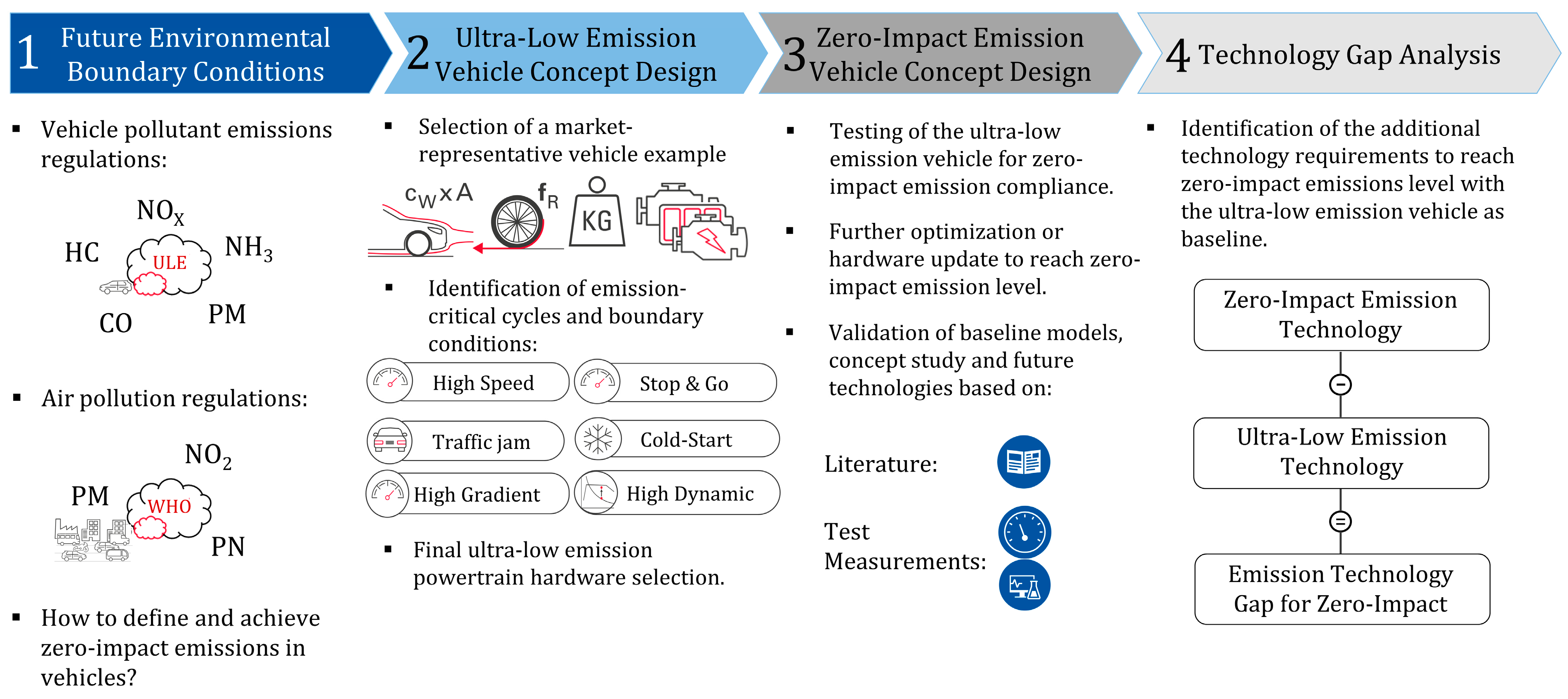
2.1. Research Approach

The research approach followed can be divided into four major individual segments, as depicted in Figure 1. These include (1) the identification of the future environmental boundary conditions for vehicles resulting from a potential vehicle emission regulatory framework and the air quality requirements that define “Zero-Impact Emission”, (2) the design of an ultra-low emission vehicle concept in accordance with the considered potential vehicle emission regulatory framework, (3) the identification of zero-impact emission powertrain technology solutions on the basis of the ultra-low emission vehicle concept, and (4) the identification of the technology “gap” between the ultra-low emission and the zero-impact emission vehicle concepts.
The considered environmental boundary conditions are a result of the synergies between two parallel research projects funded by FVV, “Science for a Moving Society”, and the European Commission’s Euro 7 regulation proposal, published in November 2022 [8]. For the baseline, ultra-low emission vehicle concept design, projections of future powertrain technologies for a market-representative LCV needed to be considered first. These were based on an extended literature study, manufacturer forecasts, and internal research.
The presented investigations are conducted on a virtual basis through simulations. For the simulations, a co-developed Matlab/Simulink (version 9.6)-based simulation platform by the Chair of Thermodynamics of Mobile Energy Conversion Systems of RWTH Aachen University and FEV Europe GmbH is used [35]. The tool enables a holistic longitudinal vehicle simulation approach for predefined driving cycles by combining existing models for all powertrain components (i.e., ICE [36,37,38], vehicle [39], and EATS [40,41,42,43]) in a single simulation environment. The base models used were validated with experimental data as far as possible. The advanced zero-impact emission technology considered is based either on available measurement data from demonstrator components or on model predictions. A more detailed description of the utilized models and simulation platform is given in Section 2.3.

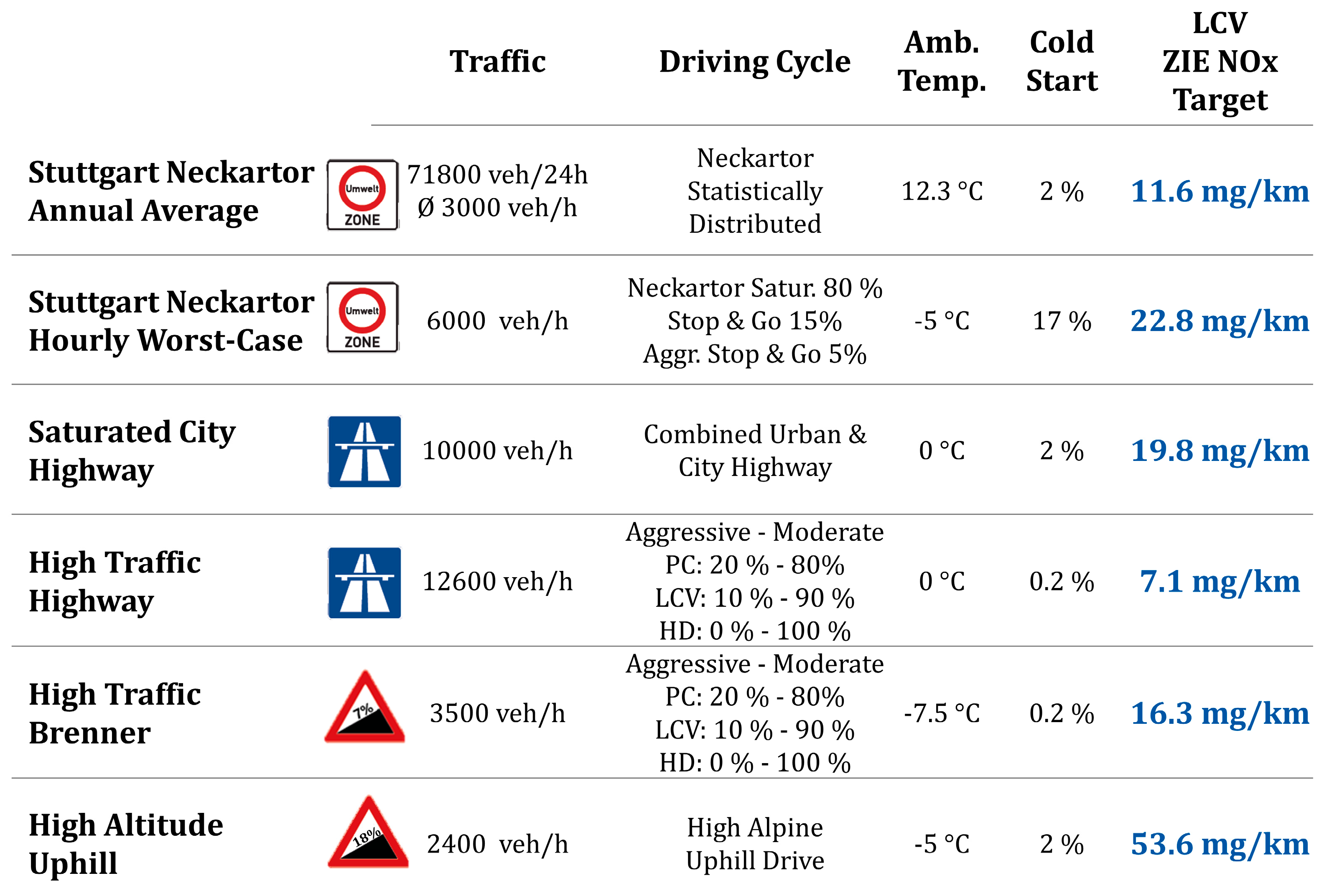
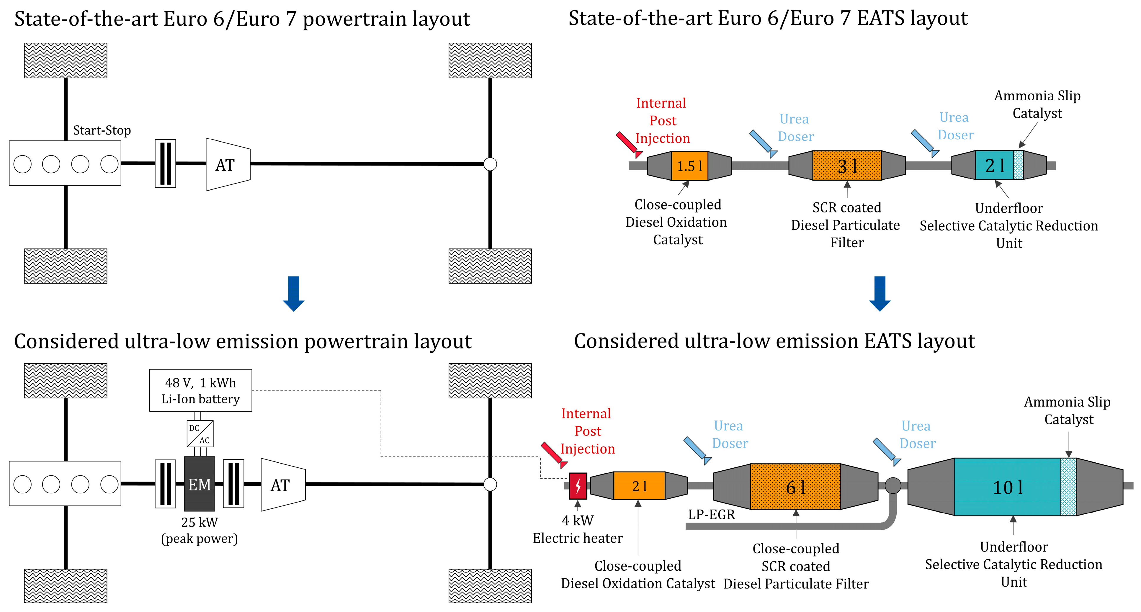
2.2. Considered Future Environmental Boundary Conditions for Vehicles

Even though the proposed Euro 7 regulations aimed to ensure ultra-low emission performance under all possible real-world operating conditions [7,8,9], it is unclear if this would be sufficient to label a generation of vehicles developed under these regulations as zero-impact emission vehicles. To determine this, first, the “Zero-Impact Emission” term must be defined. Second, a methodology for testing a vehicle’s zero-impact emission compliance must be established.
Both topics were studied in detail by Hausberger et al. [10] and Maurer et al. [11]. Based on their findings, the term “Zero-Impact Emission” can be defined as the emission level of a vehicle fleet that ensures road traffic contribution to local air quality that is smaller than a so-called “irrelevance threshold”. This was defined as 3% of the limit value for the annual mean concentration of a pollutant. Considering the WHO air quality standards of 2005 [44] for nitric oxides, this would imply a local road traffic contribution of 1.2 μg/m3 NO2 not to be exceeded in order to ensure zero-impact emission formation from the vehicle fleet.
The next step was to transfer the defined not-to-exceed road traffic contribution to the vehicle level by considering local air dilution characteristics. First, a “fleet average zero-impact emission factor (or target)” was defined as a factor that corresponded to the whole fleet. Second, a “vehicle category zero-impact emission target” was defined to correspond to each individual vehicle category in the assumed fleet of PCs, LCVs, and HDVs. Initially, the zero-impact emission targets were derived for the area of the worst-case air quality measurement station in Germany, Stuttgart at Neckartor [10,11]. The Stuttgart at Neckartor Annual Average scenario was specified. This refers to an average day of the year. The traffic flow was determined based on previous air quality studies for Neckartor, in combination with hourly values of local vehicle velocities from the traffic counting station at the Neckartor in 2016 [10,11]. The traffic flow was then related to four traffic situations according to the Handbook Emission Factors for Road Transport (HBEFA): (1) “Freeflow”, (2) “Heavy”, (3) “Saturated”, and (4) “Stop&Go” [45]. The cold start share of 2% was derived from available literature data on the share of traffic volume in the Neckartor area [11,46].
Next, based on a universal methodology presented by Maurer et al. [11], the zero-impact emission targets and boundaries defined for the Stuttgart at Neckartor Annual Average scenario were transferred to five additional real-world scenarios for LCVs. Boundary conditions, such as vehicle speed limits or fleet composition, have an impact on air quality, especially in air pollution hotspots [28]. Therefore, the additional scenarios developed combined critical aspects from both the vehicle emission formation and the air quality point of view. These can be an increased cold start share or very dynamic driving, along with increased traffic volumes or unfavorable local air ventilation conditions. The combinations cannot be arbitrary and must correspond to realistic real-world conditions [11].
As air pollution is particularly severe in urban environments, in-city vehicle operation is the primary driver for air quality initiatives. Therefore, as a first step, the Stuttgart Neckartor Annual Average scenario was adapted for an hour-specific worst-case situation, the Stuttgart Neckartor Hourly Worst-Case. With this scenario, the aim is to model an urban driving situation in which all emission and air quality relevant parameters considered in this study (i.e., driving style dynamics, the traffic flow, the cold start share, and the ambient conditions) are combined in a mostly unfavorable, yet realistic way. In this scenario, the hourly NO2 air quality target of 200 μg/m3 is applied instead of the annual mean of 40 μg/m3.
A City Highway scenario with saturated traffic is the third and last scenario modeling in-city vehicle operation. At the same time, it forms a transition situation between pure urban and highway scenarios. Next, two pure highway scenarios follow. The first one models driving on the German Highway (Autobahn A4) without a speed limit. The second one models a mountain highway with an increased road gradient, such as the Brenner Autobahn between Austria and Italy. Due to their high mean speed, average slope (in the Brenner case), and traffic flow, the High Traffic Highway and High Traffic Brenner scenarios represent critical cases for zero-impact emissions. While less frequently occurring, the last scenario is of particular interest because of the extreme conditions it represents. It models a touristic mountain road passage with extreme gradients and aggressive driving style because of hairpin turns.
The considered vehicle driving cycles for these six scenarios are derived either from publicly available data, such as the HBEFA 4.1 dataset [45] (Stuttgart scenarios) and the VECTO tool [47] (Saturated City Highway scenario), or from internally available on-road measurements performed by the Chair of Thermodynamics of Mobile Energy Conversion Systems at RWTH Aachen University (High Traffic Highway scenario) or by Professor Hausberger of TU Graz (High Traffic Brenner and High Altitude Uphill scenarios). For each scenario, the information regarding the share of each individual driving profile (i.e., percentages in the Driving Cycle column in Figure 2), the traffic flow, and the fleet composition are based on data obtained from traffic monitoring (e.g., [48,49,50,51]). Additional scenario boundary conditions, such as the cold start share, the ambient temperature, and the air dilution mechanism, are established through the analysis of available local climate data (e.g., [52]) and topography.
Last, the adopted methodology represents a significant advancement in the development of concepts of future vehicle pollutant emission regulations. Up until now, these were primarily defined on a powertrain technology-based approach and its impact assessment on related elements, such as, cost, technology implications, and CO2 emissions [53]. In total, six individual scenarios were developed for LCVs. These scenarios, together with the corresponding boundary conditions for compliance testing, are shown in Figure 2. The resulting “zero-impact emission test matrix” is used in this paper for the zero-impact emission vehicle design. A more detailed description of the driving cycles and the boundary conditions considered in the scenarios of the zero-impact emission test matrix can be found in the work presented by Maurer et al. [11].

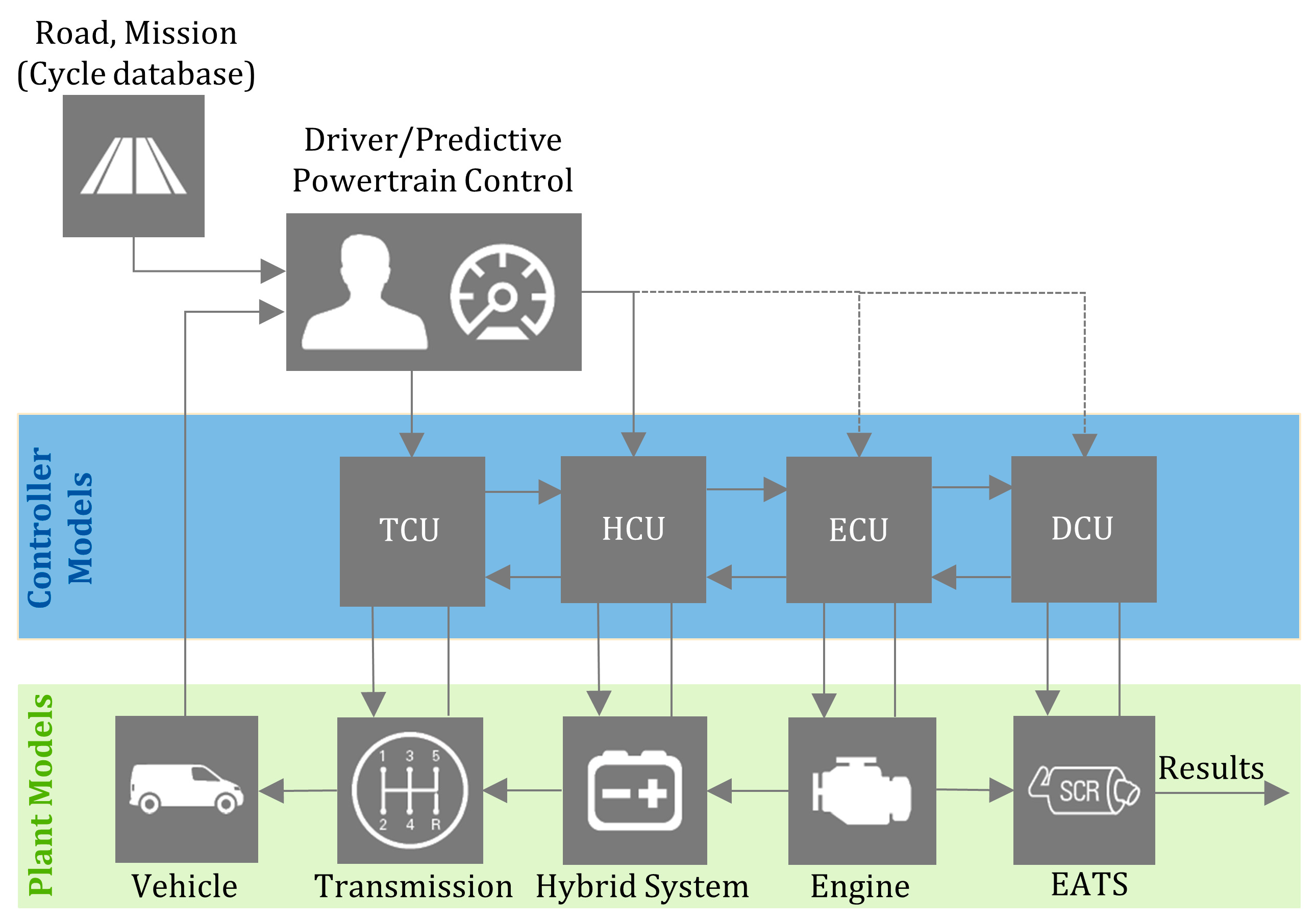
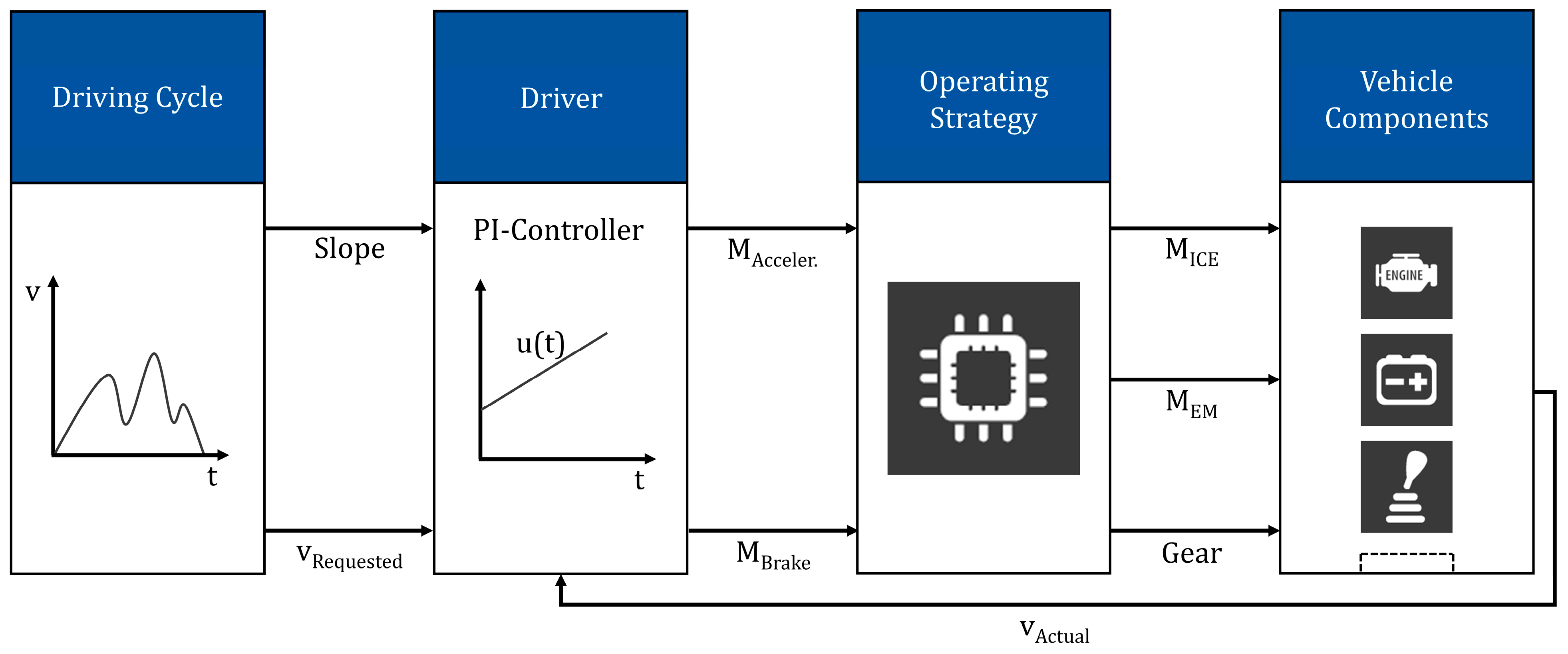
2.3. Utilized Models and Simulation Platform

The modeling principle used in the simulation platform follows a semi-physical approach. This combines parametrized 2D and 3D maps calibrated with experimental data and physical correlations formulated in mathematical equations. In comparison to other simulation and modeling techniques, the biggest advantages of the utilized simulation platform for the analysis of toxic compound emissions are (1) its ability to allow the holistic powertrain analysis, (2) its flexibility to simulate different powertrain layouts, and (3) its scalability to model and assess different applications thanks to the mean value modeling approach. The structure of this simulation platform is illustrated in Figure 3. As shown, the driver model, the control models, and the plant models are integrated into one common frame that enables their communication and synergy.
The vehicle simulation model is depicted in Figure 4. It is a longitudinal dynamics model used for driving cycle simulation. It determines powertrain energy flows and the ICE loading. A forward model is used. It includes the driving cycle, the driver, the operating strategy, and the vehicle components. The driving cycle consists of the vehicle speed and road gradient as a function of time or distance. The driver is modeled as a PI controller with feedforward control. It reacts to deviations between the targeted and the actual vehicle speed. The same applies to the driving distance. The resulting acceleration or braking request is forwarded as torque specification to the operating strategy by the “Driver” block. In order to fulfill the driver’s request, the torque coordination between the ICE and the electric motor (EM) and the gear selection are decided within the operating strategy. In the same block, the operating limits of the components are monitored. Finally, the specified operating strategy is passed on to the physical components and their control units.
This results in a torque at the wheels and, consequently, a change in vehicle speed. This is then fed back to the driver controller.
Focusing on the ICE raw emissions, the mean value engine model (MVEM), available at the Chair of Thermodynamics of Mobile Energy Conversion Systems of RWTH Aachen University, is used to simulate their formation [36,37]. Its structure allows its flexible adaptation to different hardware layouts through the activation and/or deactivation of the relevant model blocks. For the purposes of this study, the model was adapted to the chosen light-duty engine hardware. For its calibration, mapping data from a state-of-the-art Euro 6 ICE were used. These data are derived from measurements on the engine test bench. The considered ICE layout is shown in Figure 5. An overview of the engine-out performance of this ICE is given in [17].
A semi-physical approach is used in the MVEM to model the NOx emission formation. Generally, semi-physical emission modeling has important advantages compared with pure empirical approaches [38]. In the utilized MVEM, the cylinder-out NOx molar fraction is estimated based on the following correlation between O2 and NOx:
ψ N O x = ψ N O x , 0     ψ O 2 ψ O 2,0 k
Here,  ψ N O x , 0  and  ψ O 2,0  describe the previous state of the reference values for NOx and O2 [36]. The calibration of the “k” parameter is typically conducted for various correlations associated with test bench data and based on prior experience with different engines [36]. The newly formed NOx after combustion is estimated through the following formula:
d n N O x , i d t = e i j k i Δ S i ( t ) ,
In which nNOx,i represents the NOx molar quantity. This is estimated as such to equal the NO molar quantity. Each applied correlation ΔSi impacting the reaction is defined by the indices i,j [37]. More details about the modeling approach followed in the utilized MVEM can be found in [36,37,38].
Focusing on the tailpipe emissions, the utilized EATS model combines standalone models for each catalytic converter. These include the diesel oxidation catalyst (DOC), the selective catalytic reduction catalyst (SCR), and the diesel particulate filter with selective catalytic reduction coating (SDPF). The models communicate and interact with each other. An ICE mode-based control structure is implemented. This allows the holistic control of the system and enables its operation with different parametrizations. The ICE mode switch takes place by monitoring the temperature at a specified EATS position. A sensor is also modeled to allow for further EATS control capabilities (e.g., activation/deactivation of the electric heater). Several sensor blocks are included in the EATS model. These can be flexibly moved across the EATS pipeline to model different control concepts.
The SDPF and SCR models are discretized in 10 slices. Each slice includes a temperature and a NOx conversion model. As depicted in Figure 6, those models are interdependent by the parameters heat flow qcat and the catalyst temperature Tcat. To achieve the desired energy balance on a slice level, the temperature model considers temperature losses to the environment and heat from exothermic chemical reactions inside the catalyst [40,41].
The following functions are modeled in the SDPF and SCR catalysts [40,41]: (1) N H 3  storage and slip as a function of temperature and space velocity and (2)  N H 3  and  N O  oxidation. First, the available  N H 3  is oxidized to NO. Afterwards, the resulting total  N O  oxidizes to  N O 2  and shifts the  N O 2 N O x  ratio towards  N O 2 . This reaction is limited by the thermodynamic equilibrium between  N O  and  N O 2 . (3)  N O x  reduction: A priori, the reaction with equal quantities ( N O 2 N O x = 0.5 ) is calculated. In the optimal area of efficiency ( η S C R = 1 ) only one species remains. In the following, the residual  N O  and  N O 2  are reduced.
The model of the DOC catalytic converter follows a similar structure to the SCR catalyst model from the modeling approach point of view. As this catalyst is used to convert other types of emissions, different chemical reactions are modeled in this case. A more detailed description of the modeling and working principle of the DOC catalytic converter is given in [42,43,54].

3. Results and Discussion

For the investigations, an N1 Class III LCV is selected with a curb weight of 2200 kg and a gross combined weight of 3500 kg [17]. The vehicle is powered by a 2 L, 4-cylinder diesel engine with 115 kW rated power, which results in a power-to-mass ratio of less than 35 kW/t. The powertrain comprises an 8-gear automatic (AT) transmission. The aerodynamic frontal area equals 1.57 m2, and the rolling resistance coefficient is 0.0091.

3.1. Achieving Ultra-Low NOx Emissions

Figure 7 illustrates the powertrain technology upgrades considered for a state-of-the-art Euro 6/Euro 7 LCV concept [11,17] to achieve ultra-low NOx emissions.
As shown, the ultra-low NOx emission LCV concept features an EATS with significantly enlarged overall catalysts volume by 2.8 times. It is coupled with an ICE with high and low-pressure (HP and LP) exhaust gas recirculation (EGR) system and dedicated raw NOx emission improvements. To ensure the necessary deNOx performance in low-load cold starts (e.g., urban driving in winter), a 4-kW electric heater in the exhaust system is considered in addition to a 2-l DOC and a 6-l SDPF. Both catalysts are installed in a close-coupled position. For high-load trips (e.g., mountain uphill driving) with high raw emission formation, a 10-l underfloor (uf) SCR is considered. This features an ammonia slip catalyst (ASC) coating in its last part in order to prevent NH3 from slipping into the atmosphere. To enhance the prediction accuracy of the EATS model, the heat-up behavior and deNOx performance of the utilized ufSCR were validated using vehicle measurements in RDE cycles from a comparable LCV with the one investigated. By also considering the CO2 emission reduction targets from road transport until 2030 [55], the implementation of a P2 mild hybrid system can ensure both CO2 and engine raw pollutant emissions decrease, while it can also create more favorable conditions for the EATS [35,56].
The ultra-low emission vehicle concept design is based on four RDE trips. The corresponding driving cycles and operating conditions were selected as such to be challenging for emission formation from all relevant aspects. A detailed description of this design methodology and the corresponding design boundary conditions was presented by Kossioris et al. in previous work [17] and, therefore, is not further discussed here. In the same paper, the system layout and the capacity of individual system components of the adopted vehicle concept were analyzed in detail. The side effects associated with the adopted emission solutions, such as a reduction in the ICE efficiency and an increase in soot emissions, were also discussed. Finally, the tailpipe NOx emission performance of the vehicle concept was presented in detail.

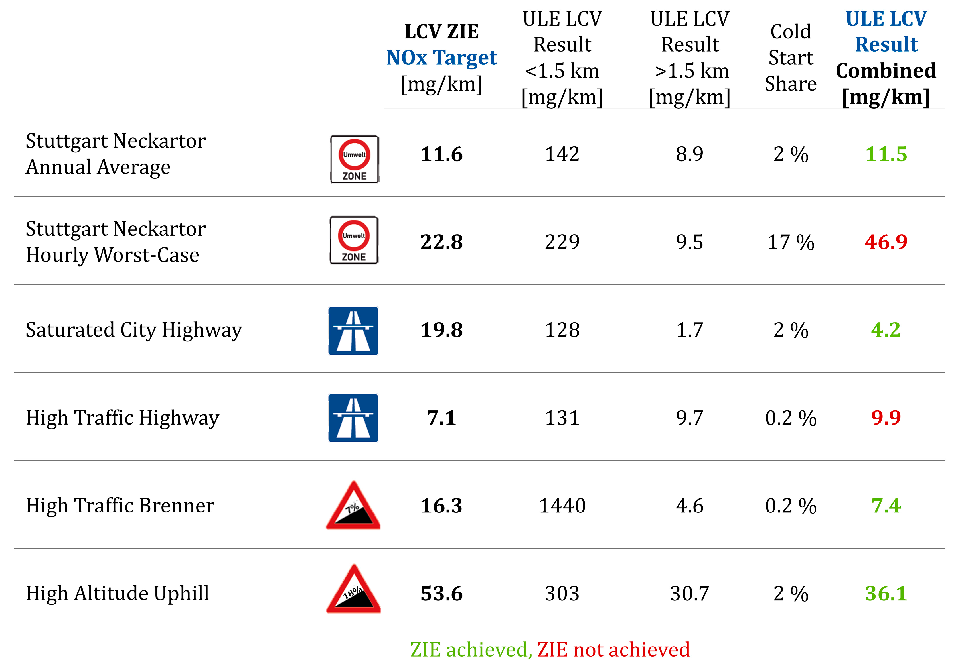
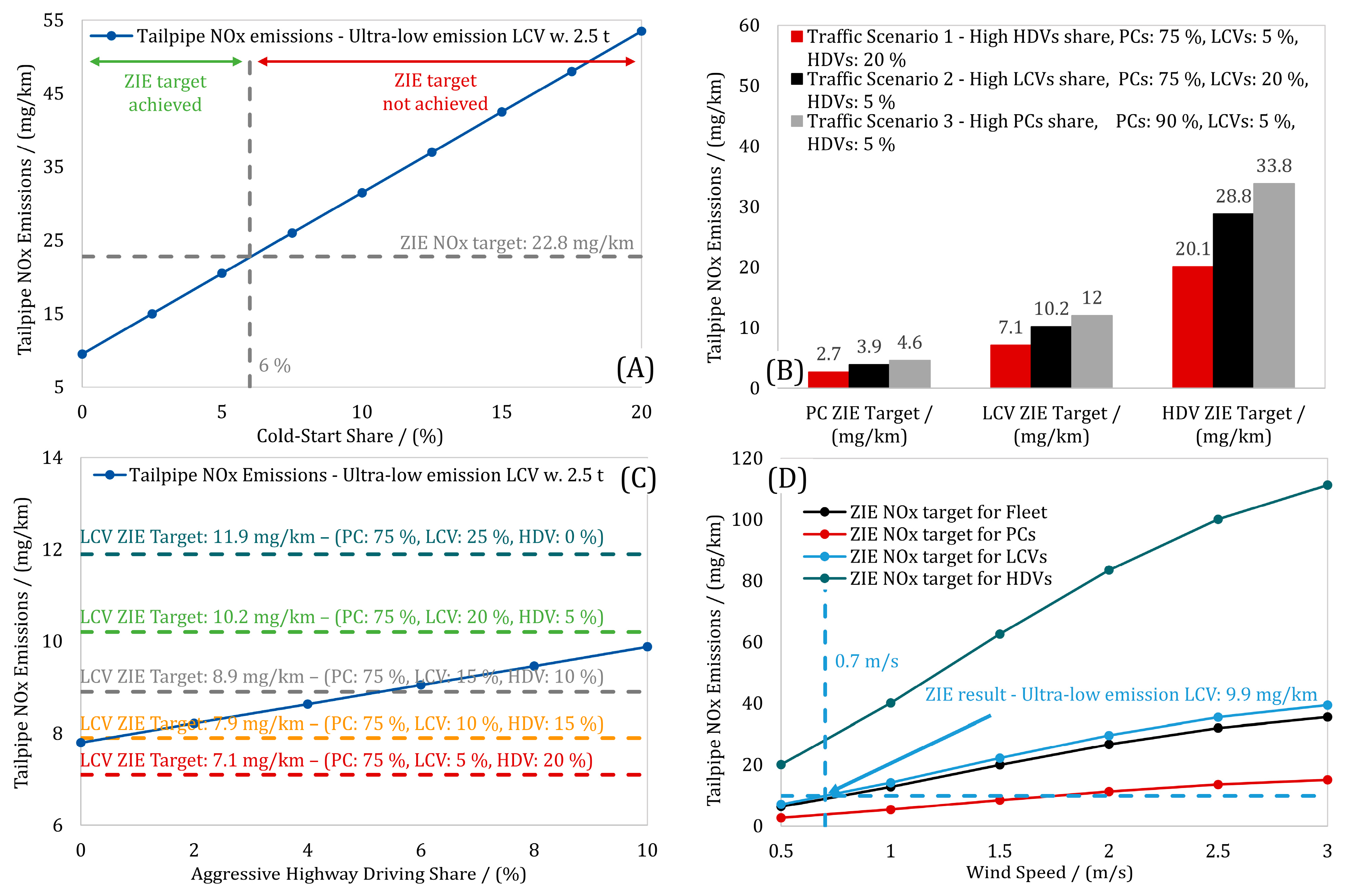
3.2. Challenges in Achieving Full Zero-Impact Emission Compliance with the Ultra-Low Emission Baseline Vehicle and Sensitivity Assessment of Key-Boundary Conditions

To quantify the challenges in achieving zero-impact NOx emissions, it is first necessary to test the ultra-low emission baseline vehicle concept under zero-impact emission boundary conditions. In Figure 8, the simulation results with the designed ultra-low emission LCV powertrain concept are shown. These include the emission result < 1.5 km (emissions impacted by cold start), the emission result > 1.5 km (emissions not impacted by cold start), the proportion of the emissions < 1.5 km in the overall combined emission result, and last, the combined emission result. The latter is the weighted sum of the emissions <1.5 km and >1.5 km, weighted by the cold start share. The methodology for the estimation of the emission results of this matrix was described in detail by Maurer et al. [11] and will not be discussed further here. The goal of this study is to ensure that the average LCV driving on the street achieves emission performance that has zero impact on air quality. Therefore, based on internally available data, an annual average payload of 25% is considered for the simulated N1 Class III LCV [11]. This results in an overall vehicle mass of 2.5 t.
As revealed through the results presented in Figure 8, the ultra-low emission vehicle already achieves zero-impact NOx emission compliance in 67% of the scenarios investigated. Particularly interesting is the fact that the ultra-low emission LCV can achieve zero-impact emissions in the “Stuttgart Neckartor Annual Average” scenario and the two mountain climbing scenarios, the “High Traffic Brenner” and the “High Altitude Uphill”. This indicates that a generation of diesel vehicles complying with the European Commission’s 2022 proposal for a Euro 7 regulation [8] would be able to ensure zero-impact emission operation inside city centers on an average day of the year. Since this can be achieved in Stuttgart at the Neckartor, a measuring point with the worst air quality in Germany and among the worst in Europe [11], zero-impact NOx emission compliance should be possible in any other European city center. This is a significant improvement compared with Euro 7 vehicles, whose NOx emissions are estimated to be approximately 2.5 times higher than the zero-impact NOx emission target in the same scenario [11].
Regarding the uphill scenarios, these are typically very challenging in terms of vehicle emission compliance because of their high average ICE loads that lead to very high raw emission formation [17]. However, from an air quality perspective, these scenarios appear to be the least critical, as shown in the results in Figure 8. This is attributed to the combination of more favorable local conditions. These contribute to higher emission targets and facilitate compliance with the zero-impact emission requirements (see Figure 2).
Looking at the scenarios in which the ultra-low emission concept is not zero-impact emission compliant, the results in Figure 8 reveal two important development challenges: (a) reductions in cold city emissions and (b) reductions in warm highway emissions.
In the first case, the combination of the increased number of vehicles driving right after a cold start and the selection of three city driving profiles with extremely low average loads and aggressive acceleration events form very critical boundary conditions for zero-impact emission compliance. However, as shown in Figure 9A, zero-impact NOx emission compliance is possible with the ultra-low emission vehicle concept up to a cold-start fraction of 6% in the “Stuttgart Neckartor Hourly Worst-Case” scenario. Achieving compliance with the assumed 17% cold-start percentage requires additional measures.
In the case of the “High Traffic Highway” scenario, achieving zero-impact NOx emission compliance is challenging mainly because of two parameters. The first one is the very low zero-impact emission target, and the second one is the aggressive driving style in the fleet. The low zero-impact emission target results from the high share of HDVs in the fleet, the high number of vehicles driving on the highways, as well as the poor local air ventilation conditions [11].
Figure 9B verifies that the higher the percentage of HDVs in the fleet, the lower the necessary emission target to achieve zero-impact NOx emissions for all vehicle classes. Simultaneously, the aggressive driving style causes an increase in transient emissions and hence renders zero-impact emission compliance more difficult. Figure 9C shows the dependency of tailpipe NOx emissions in the High Traffic Highway scenario on the driving style aggressiveness. It also demonstrates the impact of the change in the HDV share on zero-impact emission compliance while keeping the PC share unchanged. With a 10% rate of drivers displaying an aggressive driving style, zero-impact emission compliance can only be achieved when the HDV share in the fleet is lower than 6%. Moreover, even with a 0% rate of drivers displaying an aggressive driving style in the LCV fleet, zero-impact emission compliance can still marginally not be achieved in the assumed scenario. This suggests that the challenge to reach zero-impact emission compliance mainly originates from the traffic and ventilation conditions and not from the driving style.
Local ventilation conditions also play a significant role in achieving the zero-impact emission target. As a final sensitivity assessment, Figure 9D shows the impact of a change in the local wind speed on the fleet average zero-impact NOx emission target and the zero-impact NOx emission target of each individual vehicle category. The same figure also shows the zero-impact NOx emission result of the designed ultra-low emission LCV concept (Figure 8, fourth row). According to the results, the higher the wind speed, the higher the necessary zero-impact emission target for all vehicles. Considering a very challenging low wind speed situation of only 0.5 m/s, which represents the local ventilation conditions that cause the smoke to drift [57], the High Traffic Highway scenario appeared to be very challenging to achieve zero-impact emissions with the ultra-low emission LCV. However, even with a minor wind speed increase of 0.2 m/s, the ultra-low emission LCV can be zero-impact emission compliant.
Based on the above, the baseline ultra-low emission LCV concept can achieve up to 100% zero-impact NOx emission compliance in the prescribed test matrix when the local boundary conditions in the most challenging scenarios appear more relaxed. In the next section, advanced emission solutions to achieve full zero-impact NOx emission compliance are investigated and demonstrated through simulation.

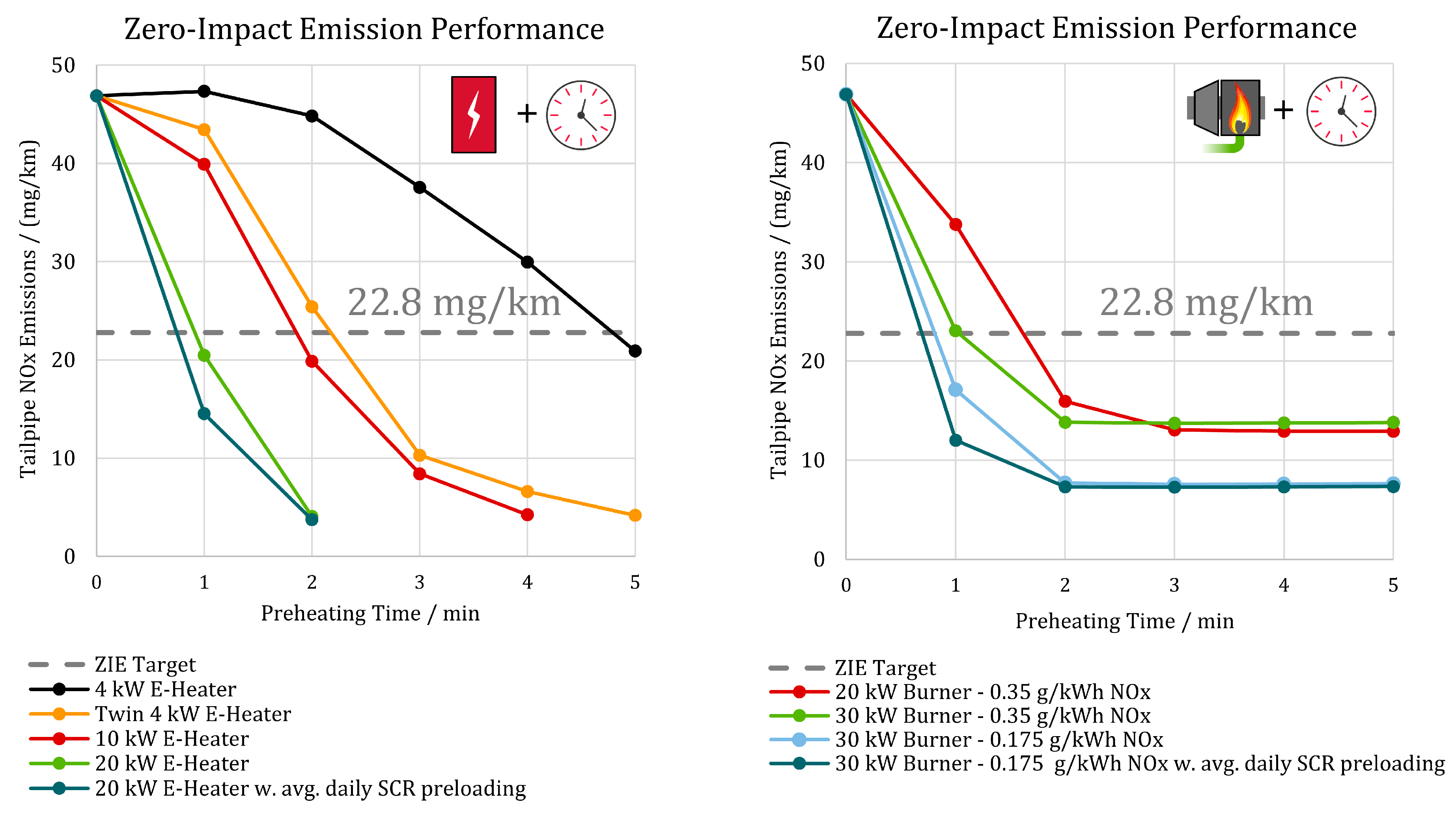
3.3. Advanced Emission Solutions to Achieve Full Zero-Impact Emission Compliance with the Ultra-Low Emission Baseline Vehicle

Figure 10 shows the advanced EATS concepts investigated to achieve zero-impact NOx emission compliance during the cold dynamic urban congestion case. In all concepts, the P2 mild hybrid system of the ultra-low emission baseline powertrain remains unchanged. During the preheating phase, the ICE remains switched off while an air pump supplies ambient air (for the E-Heater-based systems)/hot exhaust gases (for the fuel burner-based system) to the EATS. After the preheating phase, the E-Heater upstream of the ccDOC is operated in all concepts as a 4-kW unit, according to the ultra-low emission principles briefly introduced at the beginning of this section and in detail described by Kossioris et al. in [17]. All simulations were conducted with the same adverse starting boundary conditions as considered for the ultra-low emission powertrain design [17].
In addition to the scenario of adverse NH3 preloading conditions of the SCRs that minimize their deNOx performance directly after a cold start, a case with more representative NH3 values for an average day of the year was also investigated. Here, the NH3 preloading level in the SCRs was assumed to be equal to this at the end of a cold-started WLTC. The aim of the simulation studies is to demonstrate the impact of different preheating boundary conditions on achieving the zero-impact NOx emission target in less than 1 min of preheating time.
In the single E-Heater concept, it is assumed that the E-Heater can operate with different preheating power levels. Three cases of preheating are investigated, namely preheating with 4 kW, 10 kW, and 20 kW electric power. For a given preheating power level, a target air temperature is defined downstream of the E-Heater, and the air mass flow pumped into the EATS is adjusted to achieve the targeted temperature. The latter is selected accordingly to ensure SCR operation in the highest deNOx efficiency range, and restrict the air pumping requirements. These can potentially lead to packaging issues because of the inherently larger dimensioning of the air pump. Based on available measurement data, the electric power requirement for pumping ca. 12 g/s of air is about 300 W. This power requirement is scaled proportionally to the air mass flow rate of the E-Heater.
For 48-V mild hybrid systems, a 4-kW heater is currently a series production-mature technology for electrically heated catalysts, being recently under discussion for Euro 7 vehicles [7]. Therefore, the investigation of a second zero-impact NOx emission EATS concept equipped with two 4-kW E-Heaters powered by the 48-V system battery was additionally considered. In this concept, the first E-Heater should be responsible for preheating the ccDOC and the second E-Heater for the ccSDPF. After the preheating phase is completed, the 4-kW E-Heater upstream of the ccDOC operates according to the ultra-low emission powertrain principles [17], while the E-Heater upstream of the ccSDPF is deactivated. The same air mass flow rate is assumed for the twin and the single 4-kW E-Heater cases. Table 1 summarizes the system boundary conditions for the zero-impact NOx emission compliance in the “Stuttgart at Neckartor Hourly Worst-Case” scenario if electric EATS preheating is considered.
A fuel burner is the second technology option currently available in the market that can be utilized as an external EATS heating device. It is almost completely independent of the available electric energy (electricity is only necessary for the air flow pump), and it does not require an extra air pump since this is typically already part of the fuel burner device. On the market, there are already fuel burner devices with preheating power capacities above 20 kW [22,58,59]. For this study, measurement data of a 30-kW fuel burner designed for cabin heating of an HD bus is used for evaluating the potential of fuel burners in achieving zero-impact emission compliance in the Stuttgart at Neckartor Hourly Worst-Case scenario. Related measurements of energy-specific pollutant emissions from the fuel burner at different operating loads are shown in Table 2.
Two nominal burner power levels were considered, 20 kW and 30 kW. In both cases, the burner is assumed to operate at 100% load and to have the same load-dependent emission performance as the reference 30-kW fuel burner. Hence, the NOx emission level of the burner is assumed to be 0.35 g/kWh for both power levels, according to Table 2, which also represents the worst-case.
To demonstrate the impact of reducing the burner raw emissions on zero-impact emission compliance, a burner concept with 50% lower raw NOx is also investigated as an example. The resulting raw NOx emissions at 0.175 g/kWh are within the range of emissions from fuel burners found in the literature across different applications. More specifically, Battistoni et al. [58] developed a novel fuel burner for supporting the heating-up of exhaust gas aftertreatment systems for gasoline engines after a cold start. This demonstrated a 0.19 g/kWh average NOx emission level during its activation. At the same time, as reported by the Federal Association of the German Heating Industry, the manufacturers of heating oil burners below 120 kW should guarantee less than 0.11 g/kWh NOx emissions in certain test bench measurements [60].
Since the temperature of the exhaust gases leaving the fuel burner was not available, the exhaust gas mass flow rate and the exhaust gas temperatures were assumed accordingly to meet the considered burner power specifications. Similarly to the E-Heater case, the temperature of the exhaust gases leaving the fuel burner was assumed to be 450 °C for this purpose.
Figure 11 shows the impact of the preheating technology package, the preheating duration, and the SCR preloading conditions on the tailpipe NOx emissions in the “Stuttgart Hourly Worst-Case” scenario. If the market-available 4-kW E-Heater technology is used, almost 5 min preheating would be required to reach the zero-impact NOx emission target. The twin E-Heater system shows zero-impact emission performance close to the 10-kW case and can achieve the zero-impact NOx emission target after 131 s of preheating with adverse SCR NH3 preloading conditions. If the electrical preheating power is increased to 20 kW, the zero-impact emission target can be achieved after slightly less than 1 min of preheating time (i.e., 55 s) and after 45 s for more favorable SCR NH3 preloading conditions. Due to the additional NOx emission formation to produce the necessary thermal power, the 20-kW fuel burner-based system can reach the zero-impact NOx emission target after 97 s of preheating. If the burner power is increased to 30 kW with the burner raw emissions formation rate remaining the same, slightly over 1 min of preheating time (i.e., 62 s) is required to achieve the zero-impact emission target. Moreover, with the low-emission burner concept and adverse SCR NH3 preloading conditions, the zero-impact NOx emission target can be achieved after 49 s. With daily average SCR preloading conditions, the necessary preheating time drops down to 41 s.
The second technology development path to achieve full zero-impact NOx emission compliance in the defined test matrix must focus on improving the emission performance during warm highway operation, as shown in Figure 8. The major technical challenges for emission compliance under these operating conditions derive from the high average ICE load, resulting from the very high average vehicle speed. This leads to continuously high raw emission mass flows and simultaneously to high exhaust gas temperatures. Both phenomena can potentially affect the emission conversion efficiency in the SCR units, while appropriate EATS sizing is required to handle the increased emission mass flows. To address these challenges, two main solutions are investigated in this study: reducing the maximum vehicle speed and increasing the underfloor SCR volume.
The measure “reduction of maximum vehicle speed” was preferred to “vehicle power limitation”, as it is considered to be more easily communicated and understood by the driver, e.g., through a relevant warning on the dashboard. Focusing on the EU countries, there are already regulations in effect that limit the maximum permitted vehicle speed on motorways [61].
Based on this, a sensitivity assessment was conducted, and a reduction in the maximum vehicle speed down to 100 km/h was applied to those parts of the cycle where the requested speed exceeds 100 km/h. This results in the ICE operating in a lower engine-specific NOx emission area and avoids the transient acceleration phases at high vehicle speeds, thus reducing transient raw emissions while keeping the SCR inlet temperature and space velocity in a favorable range for good deNOx efficiency. As a result, very low tailpipe emissions are possible. In Figure 12 (left), the sensitivity of the zero-impact NOx emission performance of the 2.5 t ultra-low emission LCV to the reduced maximum vehicle speed in the “High Traffic Highway” scenario is depicted. As can be seen, implementing a maximum vehicle speed limit below 130 km/h (i.e., 129 km/h) can achieve zero-impact NOx emission compliance in this highway driving scenario with high traffic volume.
Another option to achieve zero-impact NOx emission compliance in the “High Traffic Highway” scenario is the increase in the overall system’s deNOx capacity as an alternative to further reduced NOx raw emissions. This can be achieved through the implementation of a larger underfloor SCR (ufSCR) catalyst. Four different ufSCR volumes were investigated namely 10 l (ultra-low emission baseline), 12 l, 14 l, and 16 l. Figure 12 (right) shows the sensitivity of the zero-impact NOx emission performance of the 2.5 t ultra-low emission LCV to an increase in the underfloor SCR volume in the “High Traffic Highway” scenario. It can be seen that the tailpipe NOx emissions decrease with the size of the ufSCR volume. Implementing an underfloor SCR with a volume of 12 l or more can achieve the zero-impact NOx emission target. A small delay in catalyst heating might occur by increasing the ufSCR volume. However, in this temperature range, this has a negligible effect on the tailpipe emissions.

4. Conclusions

In a novel approach, zero-impact NOx emission solutions for a light-duty diesel LCV have to follow a holistic design approach that considers all possible environmental boundary conditions arising from a potential vehicle emission regulation and air quality legislation. Achieving ultra-low emission levels, as set out in the European Commission’s Euro 7 regulation proposal of 2022 [8], and zero-impact emission levels require measures to reduce cold-start low-load and warm high-load emissions, which often overlap. Dynamic urban driving scenarios with congestion and highway driving scenarios with heavy traffic are the biggest challenges for zero-impact emission compliance.
The ultra-low emission baseline vehicle concept could achieve up to 100% zero-impact NOx emission compliance in the defined test matrix if the local boundary conditions, such as the proportion of cold-started vehicles in the fleet or the local wind speed, occur more relaxed in these most challenging scenarios. More specifically, a share of 6% or less of cold-started vehicles in the fleet in dynamic urban driving scenarios with congestion and the presence of light air with wind speeds above 0.7 m/s in high-traffic highway scenarios could qualify the ultra-low emission baseline vehicle already as a zero-impact emission vehicle. Moreover, in contrast to the trends shown in Euro 7 vehicle concepts [11], the ultra-low emission baseline vehicle was able to meet the zero-impact NOx emission target at one of Europe’s worst urban air quality monitoring stations, Stuttgart at the Neckartor, in an annual average driving scenario. The same vehicle in mountain climbing scenarios, such as the Brenner highway or an Alpine pass, appeared to be noncritical in terms of zero-impact emission compliance.
These results highlight that a future generation of diesel vehicles developed in accordance with the stricter Euro 7 regulation proposal than the final version of the regulation is technically feasible and could already be considered as a sustainable technology option for clean cities and transportation. Combined with green e-fuels with a net-zero CO2 footprint [20], their holistic environmental neutrality is given.
Advanced exhaust gas aftertreatment technologies can ensure zero-impact NOx emission compliance even under the most challenging conditions. Two main development directions are emerging. In dynamic urban conditions with congestion, external EATS preheating technologies are essential for the ultra-low emission baseline vehicle. Focusing on what the state-of-the-art technology can achieve, a concept with two 48-V, 4-kW E-Heaters could ensure zero-impact emission compliance after 131 s preheating time in the “Stuttgart at Neckartor Hourly Worst-Case” scenario under adverse SCR NH3 preloading conditions. With an existing 30-kW fuel burner that emits 0.35 g/kWh NOx, zero-impact emission compliance was reached after 62 s of preheating in the same scenario and under the same boundary conditions. By implementing a 20-kW high-power electric heater or a low-emission (i.e., 0.175 g/kWh NOx) 30-kW fuel burner, 55 s and 49 s preheating time is respectively required to achieve the zero-impact NOx emission target under adverse SCR NH3 preloading conditions. For average daily SCR NH3 preloading conditions, the necessary preheating time drops down to 45 s and 41 s, respectively.
For the high-traffic highway emissions, measures are required to either reduce the NOx raw emissions or increase the deNOx capacity of the EATS of the ultra-low emission baseline vehicle. Here, two solutions were examined: reducing the maximum vehicle speed and increasing the underfloor SCR volume. Reducing the ultra-low emission vehicle speed below 130 km/h can reduce the tailpipe NOx emissions to a level below zero-impact emissions. For the second solution, increasing the underfloor SCR volume from 10 l to 12 l can ensure emission levels well below the zero-impact NOx emission target.
Based on the above, several research and development directions for the emission reduction technology of diesel engines emerged. For E-Heaters, a higher power density than modern technology can provide is required if zero-impact NOx emission performance in less than 1 min of preheating is aimed. This necessitates the utilization of improved materials and cooling systems for the battery, as well as battery cells with high power densities. For powertrains requiring higher preheating power than 20 kW, high-voltage battery systems should be considered. For 48-V systems, the 20-kW power requirement is already borderline.
State-of-the-art diesel fuel burners are a step ahead of E-Heater devices in terms of zero-impact NOx emission performance because of their higher power density by almost eight times. To reduce the preheating time to the level for gasoline PCs [19], a further reduction in burner combustion emissions is required. Additional emerging research and development directions related to preheating are as follows: (1) combined preheating systems, (2) optimal selection of the desired preheating power/temperature level and its distribution in the EATS, (3) smart preheating for optimal energy and emission performance depending on the actual catalyst condition (i.e., temperature, NH3 loading), (4) preheating during ICE idling operation, and (5) preheating during pure electric driving.
Further potential towards zero-impact emissions is offered by alternative diesel-like fuels [20,62]. For example, Voelker et al. [20] showed that by making use of the remarkably lower engine-out PM emissions of drop-in, hydroformylated Fischer–Tropsch (HyFiT) e-fuels compared with fossil diesel, significant reductions in engine-out NOx emissions are possible. This can be achieved through an increase in the EGR rate. Consequently, significantly lower tailpipe NOx emissions become possible compared with fossil diesel. This indicates that e-fuel-dedicated ICE operation has the potential to reduce the size of both the deNOx system and the DPF, resulting in improved EATS heat-up behavior in cold start, improved ICE efficiency by reducing EATS-induced backpressure and cost savings [63].
Last, this study results in technical solutions needed to achieve zero-impact NOx emissions under very harsh conditions from both an environmental and a vehicle perspective. However, the situations studied, such as heavy traffic in winter with unfavorable air dilution conditions or vehicle cold starts without NH3 stored in the SCR catalysts, are not typical of everyday vehicle operation. It is likely that the extreme measures required for the adverse scenarios are not necessary in the majority of driving situations. Future research should conduct a techno-economic analysis that assesses the likelihood of these adverse situations and identifies the concepts that achieve zero-impact emissions with cost-justified and competitive additional pollution reduction measures. The zero-impact emission development should be strongly supported by specific measurements of demonstrator vehicles and/or powertrain components.

Author Contributions

Conceptualization, T.K. and R.M.; methodology, T.K. and R.M.; investigation, T.K.; resources, M.G.; writing—original draft preparation, T.K.; writing—review and editing, S.S. and M.G.; visualization, T.K.; supervision, S.P.; project administration, M.G.; funding acquisition, R.M. All authors have read and agreed to the published version of the manuscript.

Funding

This research was funded by FVV e.V., project number 1412.

Data Availability Statement

Data are partly available on request from the corresponding author with the permission of FVV e.V.

Acknowledgments

The authors would like to thank Frank Bunar (IAV GmbH), Markus Ehrly (FEV Europe GmbH), Andreas Balazs (FEV Europe GmbH), Arwa Abidi (TME, RWTH Aachen University) and Abdul Rehman Raza (TME, RWTH Aachen University) for their contribution to this paper.

Conflicts of Interest

The authors declare no conflicts of interest. The funders agreed to publish the results and gave constructive feedback on the study design, data analysis, and interpretation.

Abbreviations

The following abbreviations and symbols are used in this manuscript:
EUEuropean Union
OBMOn-Board Monitoring
RDEReal Driving Emission
ICEInternal Combustion Engine
ZIEZero-Impact Emission
NRTCNonroad Transient Cycle
ULEUltra-low Emission
LCVLight Commercial Vehicle
LDVLight-Duty Vehicle
LDLight-Duty
PCPassenger Car
HDHeavy-Duty
HDVHeavy-Duty Vehicle
LLCLow Load Cycle
FTPFederal Test Procedure
EATSExhaust Gas Aftertreatment System
LNTLean NOx Trap
HBEFAHandbook Emission Factors for Road Transport
WHOWorld Health Organization
TCUTransmission Control Unit
ECU Engine Control Unit
HCUHybrid Control Unit
DCUDoser Control Unit
EMElectric Motor
MTorque
vVehicle Speed
tTime
MVEMMean Value Engine Model
HPHigh-Pressure
LPLow-Pressure
EGRExhaust Gas Recirculation
DOCDiesel Oxidation Catalyst
SCRSelective Catalytic Reduction
DPFDiesel Particulate Filter
SDPFDiesel Particulate Filter with Selective Catalytic Reduction coating
ATAutomatic
ASCAmmonia Slip Catalyst
HPHigh-Pressure
LPLow-Pressure
ccClose-coupled
ufUnderfloor
WLTCWorldwide harmonized Light vehicles Test Cycle
SoCState-of-Charge (battery)
NO2Nitrogen Dioxide
NOxNitrogen Oxides
H2Hydrogen
CO2Carbon Dioxide
HCHydrocarbons
COCarbon Monoxide
NH3Ammonia
O2Oxygen
ψMolar Fraction

References

  1. Krecl, P.; Harrison, R.M.; Johansson, C.; Targino, A.C.; Beddows, D.C.; Ellermann, T.; Lara, C.; Ketzel, M. Long-term trends in nitrogen oxides concentrations and on-road vehicle emission factors in Copenhagen, London and Stockholm. Environ. Pollut. 2021, 290, 118105. [Google Scholar] [CrossRef] [PubMed]
  2. Harrison, R.M.; van Vu, T.; Jafar, H.; Shi, Z. More mileage in reducing urban air pollution from road traffic. Environ. Int. 2021, 149, 106329. [Google Scholar] [CrossRef] [PubMed]
  3. Hwang, H.; Choi, S.R.; Lee, J.Y. Evaluation of roadside air quality using deep learning models after the application of the diesel vehicle policy (Euro 6). Sci. Rep. 2022, 12, 20769. [Google Scholar] [CrossRef]
  4. Anenberg, S.C.; Miller, J.; Minjares, R.; Du, L.; Henze, D.K.; Lacey, F.; Malley, C.S.; Emberson, L.; Franco, V.; Klimont, Z.; et al. Impacts and mitigation of excess diesel-related NOx emissions in 11 major vehicle markets. Nature 2017, 545, 467–471. [Google Scholar] [CrossRef]
  5. European Parliament. Euro 7: Deal on New EU Rules to Reduce Road Transport Emissions; Press Room. 2023. Available online: https://www.europarl.europa.eu/news/en/press-room/20231207IPR15740/euro-7-deal-on-new-eu-rules-to-reduce-road-transport-emissions (accessed on 10 February 2025).
  6. EUR Lex. Regulation (EU) 2024/1257 of the European Parliament and of the Council of 24 April 2024 on Type-Approval of Motor Vehicles and Engines and of Systems, Components and Separate Technical Units Intended for Such Vehicles, with Respect to Their Emissions and Battery Durability (Euro 7), Amending Regulation (EU) 2018/858 of the European Parliament and of the Council and Repealing Regulations (EC) No 715/2007 and (EC) No 595/2009 of the European Parliament and of the Council, Commission Regulation (EU) No 582/2011, Commission Regulation (EU) 2017/1151, Commission Regulation (EU) 2017/2400 and Commission Implementing Regulation (EU) 2022/1362; EUR-Lex: Brussels, Belgium, 2024. [Google Scholar]
  7. Samaras, Z.; Balazs, A.; Ehrly, M.; Kontses, A.; Dimaratos, A.; Kontses, D.; Aakko, P.; Ligterink, N.; Andersson, J.; Scarbarough, T.; et al. LDV Exhaust. In Online AGVES Meeting. 2021. Available online: https://www.readkong.com/page/ldv-exhaust-presenter-prof-zissis-samaras-online-agves-9558553 (accessed on 10 February 2025).
  8. European Parliament; Council of the European Union. Proposal for a Regulation of the European Parliament and of the Council on Type-Approval of Motor Vehicles and Engines and of Systems, Components and Separate Technical Units Intended for Such Vehicles, with Respect to Their Emissions and Battery Durability (Euro 7) and Repealing Regulations (EC) No 715/2007 and (EC) No 595/2009; EUR-Lex: Brussels, Belgium, 2022. [Google Scholar]
  9. Müller, V.; Pieta, H.; Schaub, J.; Ehrly, M.; Körfer, T. On-Board Monitoring to meet upcoming EU-7 emission standards—Squaring the circle between effectiveness and robust realization. Transp. Eng. 2022, 10, 100138. [Google Scholar] [CrossRef]
  10. Hausberger, S.; Uhrner, U.; Toenges-Schuller, N.; Stadlhofer, W.; Jost, S.; Reifeltshammer, R.; Schneider, C. Zero-Impact Vehicle Emissions (Conceptual Study): Definition and Requirements of Vehicle, Zero-Impact Emission Levels “Based on Ambient Air Quality”; FVV: Frankfurt am Main, Germany, 2022. [Google Scholar]
  11. Maurer, R.; Kossioris, T.; Hausberger, S.; Toenges-Schuller, N.; Sterlepper, S.; Günther, M.; Pischinger, S. How to define and achieve Zero-Impact Emissions in road transport? Transp. Res. Transp. Environ. 2023, 116, 103619. [Google Scholar] [CrossRef]
  12. Kossioris, T.; Maurer, R. Zero-Impact Tailpipe Emissions—Test Cycles, Mendeley Data, V1. Available online: https://data.mendeley.com/datasets/z4kdp3k6dp/1 (accessed on 10 February 2025).
  13. Roiser, S.; Beringer, S.; Schutting, E.; Eichlseder, H.; Rabe, T.; Krinn, I.; Adelmann, K. Driving Hydrogen Engines Towards a Zero-Impact Emission Level. In Internationaler Motorenkongress 2023; Heintzel, A., Ed.; Springer Fachmedien Wiesbaden: Wiesbaden, Germany, 2024; pp. 17–37. ISBN 978-3-658-44981-0. [Google Scholar]
  14. Koerfer, T.; Durand, T.; Busch, H. Advanced H2 ICE Development Aiming for Full Compatibility with Classical Engines While Ensuring Zero-Impact Tailpipe Emissions. In SAE Technical Paper Series. CO2 Reduction for Transportation Systems Conference, Turin, Italy; Koerfer, T., Durand, T., Busch, H., Eds.; SAE Internationa l400 Commonwealth Drive: Warrendale, PA, USA, 2024. [Google Scholar]
  15. Koerfer, T. Advanced Engineering Tools and Methodologies to Develop Fuel-Efficient and Zero-Impact H2 Engines for On- and Off-Highway Installations. In SAE Technical Paper Series. Conference on Sustainable Mobility, Catania, Italy; Koerfer, T., Ed.; SAE International: Warrendale, PA, USA, 2024. [Google Scholar]
  16. Demuynck, J.; Mendoza Villafuerte, P.; Bosteels, D.; Kuhrt, A.; Brauer, M.; Sens, M.; Williams, J.; Chaillou, C.; Gordillo, V. Advanced Emission Controls and E-fuels on a Gasoline Car for Zero-Impact Emissions. SAE Int. J. Adv. Curr. Prac. Mobil. 2023, 5, 1063–1069. [Google Scholar] [CrossRef]
  17. Kossioris, T.; Maurer, R.; Sterlepper, S.; Günther, M.; Pischinger, S. Challenges and Solutions to Meet the Euro 7 NOx Emission Requirements for Diesel Light-Duty Commercial Vehicles. Emiss. Control Sci. Technol. 2024, 10, 123–139. [Google Scholar] [CrossRef]
  18. Kühlwein, J. Driving Resistances of Light-Duty Vehicles in Europe: Present Situation, Trends, and Scenarios for 2025. Available online: https://theicct.org/publication/driving-resistances-of-light-duty-vehicles-in-europe-present-situation-trends-and-scenarios-for-2025 (accessed on 10 February 2025).
  19. Maurer, R.; Kossioris, T.; Sterlepper, S.; Günther, M.; Pischinger, S. Achieving Zero-Impact Emissions with a Gasoline Passenger Car. Atmosphere 2023, 14, 313. [Google Scholar] [CrossRef]
  20. Voelker, S.; Groll, N.; Bachmann, M.; Mueller, L.; Neumann, M.; Kossioris, T.; Muthyala, P.; Lehrheuer, B.; Hofmeister, M.; Vorholt, A.; et al. Towards carbon-neutral and clean propulsion in heavy-duty transportation with hydroformylated Fischer–Tropsch fuels. Nat. Energy 2024, 9, 1220–1229. [Google Scholar] [CrossRef]
  21. Matheaus, A.; Neely, G.; Sharp, C.; Hopkins, J.; McCarthy, J. Fast Diesel Aftertreatment Heat-Up Using CDA and an Electrical Heater. SAE Technical Paper 2021-01-0211. 2021. Available online: https://www.sae.org/publications/technical-papers/content/2021-01-0211/ (accessed on 10 February 2025).
  22. Hassdenteufel, A.; Schünemann, E.; Neubert, V.; Hirchenhein, A. Gasoline powertrain solutions with ultra low tailpipe emissions. Transp. Eng. 2022, 8, 100109. [Google Scholar] [CrossRef]
  23. Demuynck, J.; Favre, C.; Bosteels, D.; Randlshofer, G.; Bunar, F.; Spitta, J.; Friedrichs, O.; Kuhrt, A.; Brauer, M. Integrated Diesel System Achieving Ultra-Low Urban and Motorway NOx Emissions on the Road Reduzierung von NOx-Emissionen im realen Stadt- und Autobahnfahrbetrieb mit optimiertem Dieselantrieb. In Proceedings of the 40th Vienna Motor Symposium, Vienna, Austria, 16–17 May 2019. [Google Scholar]
  24. Lau, J.; Hatzopoulou, M.; Wahba, M.M.; Miller, E.J. Integrated Multimodel Evaluation of Transit Bus Emissions in Toronto, Canada. Transp. Res. Rec. 2011, 2216, 1–9. [Google Scholar] [CrossRef]
  25. Coelho, M.C.; Frey, H.C.; Rouphail, N.M.; Zhai, H.; Pelkmans, L. Assessing methods for comparing emissions from gasoline and diesel light-duty vehicles based on microscale measurements. Transp. Res. Transp. Environ. 2009, 14, 91–99. [Google Scholar] [CrossRef]
  26. Coelho, M.C.; Farias, T.L.; Rouphail, N.M. Effect of roundabout operations on pollutant emissions. Transp. Res. Transp. Environ. 2006, 11, 333–343. [Google Scholar] [CrossRef]
  27. Coelho, M.C.; Farias, T.L.; Rouphail, N.M. Impact of speed control traffic signals on pollutant emissions. Transp. Res. Transp. Environ. 2005, 10, 323–340. [Google Scholar] [CrossRef]
  28. Tang, J.; McNabola, A.; Misstear, B.; Pilla, F.; Alam, M.S. Assessing the Impact of Vehicle Speed Limits and Fleet Composition on Air Quality Near a School. Int. J. Environ. Res. Public Health 2019, 16, 149. [Google Scholar] [CrossRef]
  29. Alam, M.S.; Georgakis, P. The State of the Art of Cooperative and Connected Autonomous Vehicles from the Future Mobility Management Perspective: A Systematic Review. Future Transp. 2022, 2, 589–604. [Google Scholar] [CrossRef]
  30. Bandeira, J.M.; Macedo, E.; Fernandes, P.; Rodrigues, M.; Andrade, M.; Coelho, M.C. Potential Pollutant Emission Effects of Connected and Automated Vehicles in a Mixed Traffic Flow Context for Different Road Types. IEEE Open J. Intell. Transp. Syst. 2021, 2, 364–383. [Google Scholar] [CrossRef]
  31. Peters, J.F.; Burguillo, M.; Arranz, J.M. Low emission zones: Effects on alternative-fuel vehicle uptake and fleet CO2 emissions. Transp. Res. Part D Transp. Environ. 2021, 95, 102882. [Google Scholar] [CrossRef]
  32. Sánchez, J.M.; Ortega, E.; López-Lambas, M.E.; Martín, B. Evaluation of emissions in traffic reduction and pedestrianization scenarios in Madrid. Transp. Res. Transp. Environ. 2021, 100, 103064. [Google Scholar] [CrossRef]
  33. Gonzalez, J.N.; Gomez, J.; Vassallo, J.M. Do urban parking restrictions and Low Emission Zones encourage a greener mobility? Transp. Res. Transp. Environ. 2022, 107, 103319. [Google Scholar] [CrossRef]
  34. Sampaio, C.; Coelho, M.C.; Macedo, E.; Bandeira, J.M. Emissions based tolls—Impacts on the total emissions of an intercity corridor. Transp. Res. Part D Transp. Environ. 2021, 101, 103093. [Google Scholar] [CrossRef]
  35. Schaub, J.; Sammito, G.; Lindemann, B.; Kansy, W.; Muthyala, P.P.; Vogt, K.; Ehrly, M.; Lingemann, P.; Pischinger, S. Hybrid Powertrain Concepts for Light Commercial Vehicles. In 29. Aachen Colloquium Sustainable Mobility: October 5th–7th; Institute for Automotive Engineering; RWTH Aachen University: Aachen, Germany, 2020. [Google Scholar]
  36. Picerno, M.; Lee, S.-Y.; Schaub, J.; Ehrly, M.; Millo, F.; Scassa, M.; Andert, J. Co-Simulation of Multi-Domain Engine and its Integrated Control for Transient Driving Cycles. IFAC—PapersOnLine 2020, 53, 13982–13987. [Google Scholar] [CrossRef]
  37. Lee, S.-Y.; Andert, J.; Pischinger, S.; Ehrly, M.; Schaub, J.; Koetter, M.; Ayhan, A.S. Scalable Mean Value Modeling for Real-Time Engine Simulations with Improved Consistency and Adaptability; SAE Technical Paper 2019-01-0195; SAE International: Warrendale, PA, USA, 2019. [Google Scholar] [CrossRef]
  38. Quérel, C.; Grondin, O.; Letellier, C. Semi-physical mean-value NOx model for diesel engine control. Control Eng. Pract. 2015, 40, 27–44. [Google Scholar] [CrossRef]
  39. Maiterth, J.M. Gesamtkosten-und emissionsoptimierte Systemauslegung von Nutzfahrzeug-Hybridantriebssträngen. Ph.D. Thesis, RWTH Aachen University, Aachen, Germany, 2022. [Google Scholar]
  40. Vagnoni, G.; Karim, M.R.; Petri, S.; Lindberg, J.; Pantaleo, A.; Aubeck, F.; Schaub, J.; Mugovski, N.; Gelso, E.R. Predictive engine and aftertreatment control concepts for a heavy-duty long haul truck. In 27. Aachen Colloquium Automobile and Engine Technology: October 8th–10th; Institute for Automotive Engineering (RWTH Aachen): Aachen, Germany, 2018. [Google Scholar]
  41. Schönen, M.; Rosefort, Y.; Das, A.; Özyalcin, I.C.; Koll, V. Improved SCR Simulation and Control by Kinetic Modelling of the SCR Catalyst. In THIESEL Conference 2014: 9th–12th September, 8th Edition of the International Conference on Thermo-and Fluid Dynamic Processes in Direct Injection Engines; Conference Proceedings: Valencia, Spain, 2014. [Google Scholar]
  42. Laible, T. Aufbau eines Laborgasprüfstandes zur Entwicklung und Validierung von kalibrierbaren Katalysatormodellen. Ph.D. Thesis, RWTH Aachen University, Aachen, Germany, 2018. [Google Scholar]
  43. Omari, A. Characterization of Polyoxymethylen Dimethyl Ether for Diesel Engine Applications. Ph.D. Thesis, RWTH Aachen University, Aachen, Germany, 2021. [Google Scholar]
  44. WHO. WHO Air Quality Guidelines: Global Update 2005; World Health Organization: Copenhagen, Denmark, 2006; ISBN 9789289021920. [Google Scholar]
  45. INFRAS. Handbook Emission Factors for Road Transport (HBEFA): 3.1e Dokumentation; Infras: Philadelphia, PA, USA, 2010; Available online: https://www.hbefa.net/e/index.html (accessed on 22 June 2022).
  46. Friedrich, M. PKW-Fahrtweiten und Fahrzeiten zum Neckartor. Memo. 2017. Available online: https://www.isv.uni-stuttgart.de/institut/team/Friedrich-00003/ (accessed on 23 June 2022).
  47. European Commission. Vehicle Energy Consumption Calculation Tool—VECTO. Available online: https://ec.europa.eu/clima/eu-action/transport-emissions/road-transport-reducing-co2-emissions-vehicles/vehicle-energy-consumption-calculation-tool-vecto_en (accessed on 22 June 2022).
  48. LUBW. Traffic Counts in Baden-Württemberg. Available online: https://www7.lubw.baden-wuerttemberg.de/luft/verkehrszaehlungen-in-baden-wuerttemberg (accessed on 22 June 2022).
  49. LUBW. Maximum Traffic Volume per Hour at Neckartor in Stuttgart. E-Mail Correspondence with Mr. Helmut Scheu-Hachtel. 2022. Available online: https://www.lubw.baden-wuerttemberg.de/startseite (accessed on 23 June 2022).
  50. Federal Highway Research Institute. Automatische Zählstellen 2019. Available online: https://www.bast.de/DE/Verkehrstechnik/Fachthemen/v2-verkehrszaehlung/Daten/2019_1/Jawe2019.html?nn=1819490&cms_detail=5037&cms_map=0 (accessed on 22 June 2022).
  51. Federal Highway Research Institute. Automatische Zählstellen 2020. Available online: https://www.bast.de/DE/Verkehrstechnik/Fachthemen/v2-verkehrszaehlung/Aktuell/zaehl_aktuell_node.html (accessed on 22 June 2022).
  52. Zentralanstalt für Meteorologie und Geodynamik. Klimanormalwerte Österreich 1991–2020. Available online: https://www.zamg.ac.at/cms/de/klima/informationsportal-klimawandel/daten-download/copy_of_klimamittel (accessed on 22 June 2022).
  53. CLOVE Consortium. Preliminary Findings on Possible Euro 7 Emission Limits for LD and HD Vehicles. Available online: https://circabc.europa.eu/sd/a/fdd70a2d-b50a-4d0b-a92a-e64d41d0e947/CLOVE%20test%20limits%20AGVES%202020-10-27%20final%20vs2.pdf (accessed on 10 February 2025).
  54. Kwee, J.H.; Abel, D.; Pischinger, S. Gesamtsystembetrachtung Eines Diesel-Elektrischen Hybrid-Linienbusses unter Besonderer Berücksichtigung des SCR-Abgasnachbehandlungssystems: Lehrstuhl für Verbrennungskraftmaschinen und Institut für Thermodynamik. Ph.D. Thesis, Rheinisch-Westfälische Technische Hochschule Aachen, Aachen, Germany, 2019. [Google Scholar]
  55. Suarez, C.J.; Komnos, D.; Ktistakis, M.; Fontaras, G. 2025 and 2030 CO2 Emission Targets for Light Duty Vehicles; Publications Office of the European Union: Luxembourg, 2023. [Google Scholar]
  56. Kossioris, T.; Schaub, J.; Ehrly, M.; Maiterth, J.; Keizer, R.; an der Put, D. Evaluation of a Serial-parallel Hybrid Powertrain Concept for a Heavy Duty Truck. In FISITA World Congress 2021—Technical Programme; FISITA World Congress 2021; FISITA: Bishop’s Stortford, UK, 2021; ISBN 9781916025929. [Google Scholar]
  57. Charles, W.; Finkl, C.M. (Eds.) Encyclope dia of Coastal Science; Springer Nature Switzerland AG: Cham, Switzerland, 2019. [Google Scholar]
  58. Battistoni, M.; Zembi, J.; Casadei, D.; Ricci, F.; Martinelli, R.; Grimaldi, C.; La Sana, M.; Brignone, M.; Mantovanelli, A.; Milani, E. Burner Development for Light-Off Speed-Up of Aftertreatment Systems in Gasoline SI Engines; SAE International: Warrendale, PA, USA, 2022. [Google Scholar] [CrossRef]
  59. zu Schweinsberg, A.S.; Klenk, M.; Degen, A. Engine-Independent Exhaust Gas Aftertreatment Using a Burner Heated Catalyst; SAE International: Warrendale, PA, USA, 2006. [Google Scholar] [CrossRef]
  60. Bundesverband der Deutschen Heizungsindustrie. NOx-Emission bei Feuerungsanlagen. Information Sheet No. 66. 2020. Available online: https://www.bdh-industrie.de/fileadmin/user_upload/Publikationen/Infoblaetter/Infoblatt_Nr_66_NOx-Emission_Feuerungsanlagen_022020.pdf (accessed on 6 June 2023).
  61. European Union. Road Rules and Safety. Available online: https://europa.eu/youreurope/citizens/travel/driving-abroad/road-rules-and-safety/index_en.htm (accessed on 24 September 2024).
  62. Zhang, Z.; Ye, J.; Tan, D.; Feng, Z.; Luo, J.; Tan, Y.; Huang, Y. The effects of Fe2O3 based DOC and SCR catalyst on the combustion and emission characteristics of a diesel engine fueled with biodiesel. Fuel 2021, 290, 120039. [Google Scholar] [CrossRef]
  63. Lehrheuer, B.; Kossioris, T.; Muthyala, P.P.; Neumann, M.; Pischinger, S. Hydroformylated Fischer-Tropsch Fuels for Sustainable Transport. In Proceedings of the Conference on Powertrains with Renewable Energy Carriers, Stuttgart, Germany, 28–29 November 2023. [Google Scholar]
Figure 1. Research approach.
Energies 18 01882 g001
Figure 2. Boundary conditions and NOx emission targets of the zero-impact emission test matrix scenarios [11,12].
Energies 18 01882 g002
Figure 3. Structure of the utilized simulation platform [35].
Energies 18 01882 g003
Figure 4. Structure of the vehicle simulation model [39].
Energies 18 01882 g004
Figure 5. Considered light-duty ICE layout.
Energies 18 01882 g005
Figure 6. Modeling principle of the discrete multi-scale SCR model [40,41].
Energies 18 01882 g006
Figure 7. Considered ultra-low emission technology compared with state-of-the-art Euro 6/Euro 7 technology [17].
Energies 18 01882 g007
Figure 8. NOx performance of the ultra-low emission LCV with 25% payload under the zero-impact emission boundary conditions shown in Figure 2.
Energies 18 01882 g008
Figure 9. (A) Sensitivity of zero-impact NOx emission compliance of the ultra-low emission LCV with 25% payload with respect to the proportion of vehicles that made a cold start shortly before in the hourly worst-case scenario in Stuttgart at Neckartor (B) Sensitivity of the zero-impact NOx emission target to the HDVs share in the High Traffic Highway scenario (C) Sensitivity of zero-impact NOx emission compliance of the ultra-low emission LCV to the proportion of HDVs and the driving style aggressiveness in the High Traffic Highway scenario (D) Impact of wind speed on zero-impact NOx emission compliance of the ultra-low emission LCV with 2.5 t in the High Traffic Highway scenario.
Energies 18 01882 g009
Figure 10. Advanced EATS concepts to achieve zero-impact NOx emission compliance in the Stuttgart at Neckartor Hourly Worst-Case scenario with the investigated N1 Class III P2-MHEV diesel LCV shown in Figure 7 (bottom, left).
Energies 18 01882 g010
Figure 11. Achieving zero-impact NOx emissions in the Stuttgart Hourly Worst-Case scenario with the 2.5 t P2-MHEV diesel LCV equipped with the advanced EATS concepts shown in Figure 10.
Energies 18 01882 g011
Figure 12. Achieving zero-impact NOx emissions in the High Traffic Highway scenario with the 2.5 t P2-MHEV diesel LCV equipped with the ultra-low emission EATS concept shown in Figure 7 (bottom, right).
Energies 18 01882 g012
Table 1. System boundary conditions for the zero-impact NOx emission compliance with the electrically preheated EATS concepts depicted in Figure 10 in the Stuttgart at Neckartor Hourly Worst-Case scenario.
Electric
Preheating
Power
Air Mass Flow Rate/
(g/s)
DOC Inlet Air Temperature/
(°C)
Electric Power Consumed During Preheating/(kWh/min)SoC After
Preheating/
(%)
NH3 Starting
Load/
(-)
4 kW12.43000.072155% of max. storage
8 kW (2 × 4 kW)12.43000.138155% of max. storage
10 kW20.74500.175155% of max. storage
20 kW41.54500.35155% of max. storage
20 kW (avg. NH3 preloading41.54500.3515WLTC end-value
Table 2. Pollutant emissions from the 30-kW diesel fuel burner at different loads.
Load/
(%)
CO/
(g/kWh)
NOx/
(g/kWh)
HC/
(g/kWh)
Soot/
(g/kWh)
257.20.270.020.29
508.50.280.020.30
757.90.30.020.27
1007.90.350.020.18
Disclaimer/Publisher’s Note: The statements, opinions and data contained in all publications are solely those of the individual author(s) and contributor(s) and not of MDPI and/or the editor(s). MDPI and/or the editor(s) disclaim responsibility for any injury to people or property resulting from any ideas, methods, instructions or products referred to in the content.

