Article

Enhanced Harmonic Reduction and Voltage Utilization Ratio Improvement in ANPC Inverters Using an Advanced Hybrid SVPWM Technique

Department of Electrical Engineering, Gachon University, Seongnam-si 13120, Republic of Korea
*
Author to whom correspondence should be addressed.
Energies 2025, 18(7), 1868; https://doi.org/10.3390/en18071868
Submission received: 12 February 2025 / Revised: 18 March 2025 / Accepted: 24 March 2025 / Published: 7 April 2025
(This article belongs to the Section F3: Power Electronics)

Abstract

:
This paper proposes an Advanced Hybrid SVPWM (Space Vector Pulse Width Modulation) technique that integrates the benefits of RPS-PWM (Reference Point Saturation-Based PWM) and SVPWM to enhance the performance of three-level ANPC (Active Neutral Point Clamped) inverters. While RPS-PWM effectively reduces switching harmonics, it suffers from lower voltage utilization. In contrast, SVPWM achieves higher voltage utilization but struggles with harmonic suppression. The proposed Advanced Hybrid SVPWM technique addresses these limitations by maintaining the voltage utilization level of RPS-PWM while significantly reducing harmonic distortion and increasing the output V r m s . To validate the effectiveness of the proposed method, comprehensive PSIM simulations and DSP-based hardware experiments were conducted. Experimental results confirm that the Advanced Hybrid SVPWM achieves superior harmonic suppression compared to conventional RPS-PWM and SVPWM, while also delivering improved output voltage characteristics. These findings highlight the potential of the proposed technique for enhancing the performance of power electronic systems requiring high efficiency and low harmonic distortion.

1. Introduction

With the increasing demand for high-performance power converters, various Pulse Width Modulation (PWM) control techniques have been developed to enhance the efficiency and quality of power conversion [1,2]. PWM is widely employed in power electronic converters to regulate output voltage, minimize harmonic distortion, and optimize overall system performance [3,4,5]. Among the conventional PWM techniques, Sinusoidal Pulse Width Modulation (SPWM) and Space Vector Pulse Width Modulation (SVPWM) have been extensively utilized for three-phase inverters. SPWM is a simple and widely adopted modulation technique that compares sinusoidal reference waveforms with triangular carrier signals to generate switching pulses. While SPWM provides ease of implementation, it suffers from limitations such as poor voltage utilization and increased total harmonic distortion (THD) due to the nature of its modulation scheme. Additionally, SPWM exhibits suboptimal performance in multilevel inverters, where maintaining symmetrical and efficient switching patterns is critical [6]. SVPWM, in contrast, is a more advanced technique that utilizes a space vector representation of the three-phase system to optimize switching sequences. This results in improved voltage utilization and reduced THD compared to SPWM. However, despite its advantages, SVPWM still faces challenges in harmonic suppression, particularly in multilevel inverters such as the three-level Active Neutral Point Clamped (ANPC) inverter. The complexity of its switching pattern calculations also presents implementation challenges, requiring higher computational resources for real-time control [7,8,9]. To address the limitations of conventional PWM techniques, researchers have explored various hybrid modulation strategies that integrate multiple PWM methods to enhance performance. One such approach is the Reference point Saturation-Based (RPS-B) PWM technique, which introduces Reference point saturation pulse switching strategies to mitigate harmonic spikes and distribute switching losses more evenly across semiconductor devices. By reducing the concentration of harmonic components at specific frequencies, RPS-B PWM improves power quality and reduces electromagnetic interference (EMI) issues. However, RPS-B PWM has limitations in terms of voltage utilization, making it less efficient in achieving high output voltage amplitudes [10,11,12]. Given the limitations of existing PWM techniques, this paper proposes an Advanced Hybrid SVPWM technique that integrates the benefits of RPS-B PWM and SVPWM. The proposed method aims to achieve lower harmonic distortion, enhanced voltage utilization, and reduced switching losses, making it particularly suitable for multilevel inverters.

2. Analysis of Various PWM Techniques in Inverters and Application Strategies for the Advanced Hybrid SVPWM Technique

2.1. Analysis of the SPWM Technique

The three-level SPWM (Sinusoidal Pulse Width Modulation) is a fundamental control technique commonly used in multilevel inverters. The reference signal defines the target waveform for the output voltage, and the switching operation is determined based on the intersection points with two carrier signals (upper and lower carrier signals). When the reference signal crosses the carrier signals, the output voltage is modulated to +Vdc/2, 0, or −Vdc/2, resulting in the generation of a three-level voltage. While the SPWM technique enables the generation of an output voltage close to a sine wave with a simple implementation, it has limitations in terms of Total Harmonic Distortion (THD) and switching losses.

2.2. Analysis of the SVPWM Technique

The SVPWM (Space Vector Pulse Width Modulation) technique is a control method based on space vector theory that calculates switching times for each sector to control the three-phase output voltage. The SVPWM (Space Vector Pulse Width Modulation) technique is a control method based on space vector theory (see Figure 1). Figure 1 visually represents the six sectors and the switching states used in each sector, illustrating the process of decomposing the reference voltage vector into two voltage vectors within the corresponding sector. The red dashed circle indicates the trajectory of the space voltage vector, while the asterisk ( V * ) denotes the instantaneous position of the reference voltage vector in the sector. For example, when the reference voltage vector is located in Sector 1, it is expressed as a linear combination of the vectors [1 0 0] and [1 1 0], with the switching times determined by the weighting of each vector. This method effectively reduces Total Harmonic Distortion (THD) of the output voltage and maximizes voltage utilization. However, SVPWM is more complex to implement compared to SPWM and requires real-time computations, posing significant challenges in the design and implementation of the control algorithm [13,14,15,16,17,18,19,20].

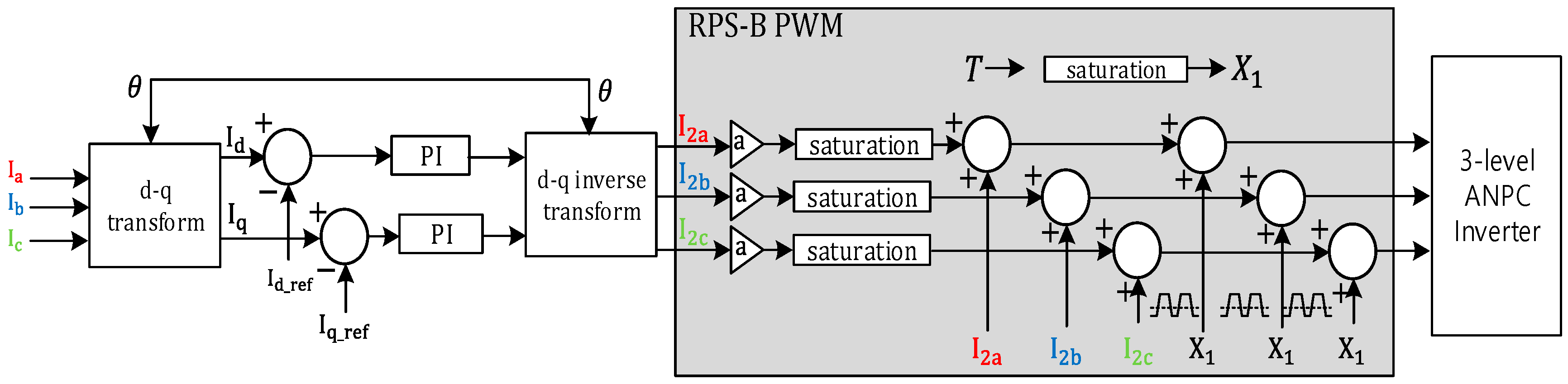
2.3. Analysis of the RPS-B PWM Technique [21]

As shown in Figure 2, the Reference Point Saturation-Based PWM technique features a simpler control algorithm compared to SVPWM and operates by combining modulated signals with saturation signals to enhance the precision of the output signals. This method compensates for current errors using a PI controller in the dq-coordinate system through Park and Clarke transformations and subsequently transforms the signals back to the abc-coordinate system to generate three-phase output signals. The generated modulation signals are integrated with common-mode voltage suppression to improve voltage quality. However, the ability of this technique to suppress common-mode voltage is more limited compared to SVPWM.

2.4. Operation and Control Method of the Proposed Advanced Hybrid SVPWM Technique

The Advanced Hybrid SVPWM technique proposed in this paper is designed to effectively achieve two primary objectives: harmonic suppression and enhancement of output quality. By combining the advantages of the existing RPS-B PWM and SVPWM methods, this technique provides a robust solution for multilevel inverters. Figure 3 visually illustrates the control block diagram of the proposed method, systematically representing the overall operation process.
First, the input signals from the three-phase current sensors are transformed into the rotating dq-coordinate system through the park transformation. In this process, the d-axis component represents the active current, while the q-axis component corresponds to the reactive current, both of which are treated as time-invariant signals. This transformation allows the current controller to apply linear control algorithms, such as PI control, to maximize control efficiency.
The controlled dq signals are then converted back into three-phase signals (abc-coordinate system) via the inverse park transformation. During this process, the d-axis and q-axis signals are transformed into time-varying three-phase sinusoidal signals.
The transformed sinusoidal waveforms are scaled through an adjustment factor ( X 1 ) and input into the RPS-B PWM technique. In this stage, the signals for each phase undergo a saturation process, restricting them within specific limits. The processed signals are then passed to the SVPWM method, which generates the final switching signals. The SVPWM method, based on the space vector diagram, represents the reference vector’s position as a weighted combination of active voltage vectors and zero vectors within a specific sector.
As a result, the Advanced Hybrid SVPWM technique leverages the complementary advantages of RPS-B PWM and SVPWM to maximize harmonic suppression performance and enhance output voltage and current quality. Additionally, this method reduces switching losses that can occur in conventional PWM techniques and ensures stable switching operation.

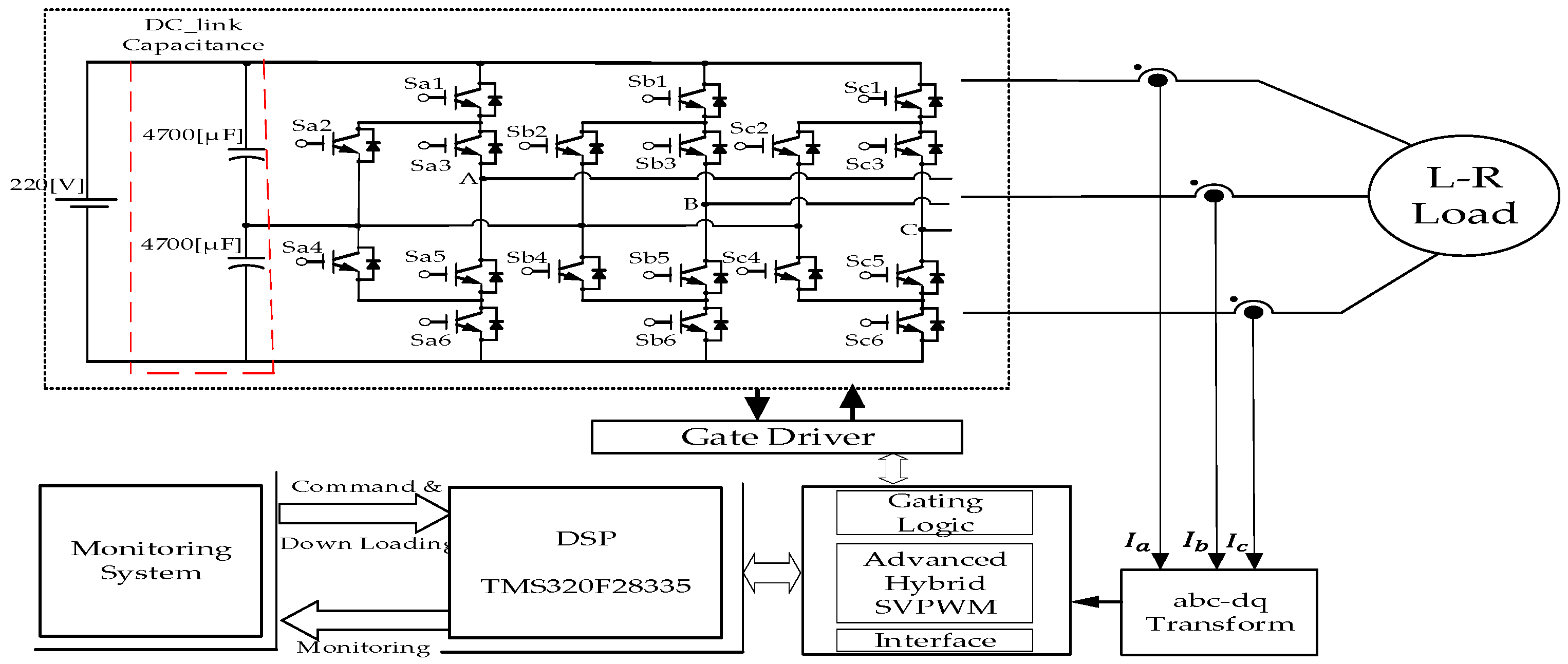
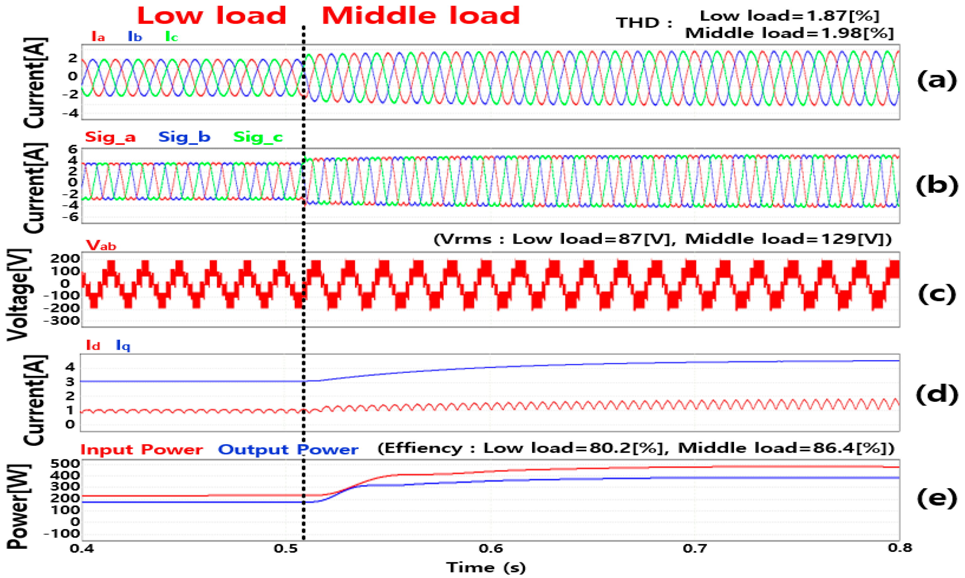
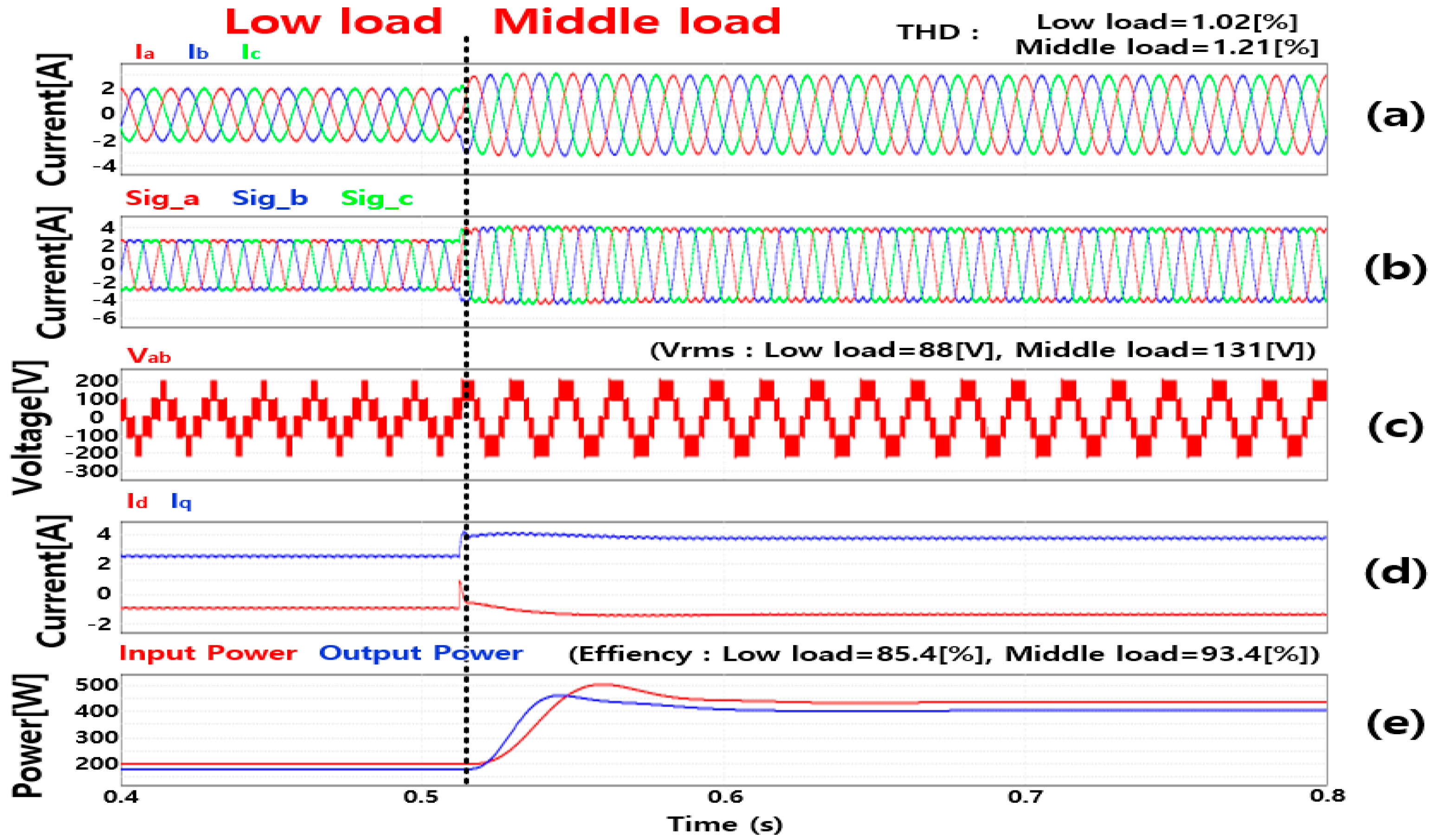
3. Simulation Performance Verification of the Proposed Advanced Hybrid SVPWM Technique

In this paper, simulations were conducted to analyze the performance improvements of the proposed Advanced Hybrid SVPWM technique in a three-level ANPC (Active Neutral Point Clamped) inverter. Figure 4 illustrates the simulation circuit configuration of the ANPC inverter. In this experiment, two DC-link capacitors were used to regulate power supply, and an LR equivalent circuit was applied instead of a motor. The voltage of the DC-link capacitors was set to 220 [V], and the switching frequency was configured to 20 [kHz] to control the inverter’s operation. The LR equivalent circuit consisted of an inductor with a value of 28.14 [mH] and a resistor with a value of 30 [Ω], with the output frequency set to 60 [Hz]. The capacitance of each DC-link capacitor was configured as 4700 [µF].
The PWM techniques were tested under experimental conditions where the current was set to vary dynamically between low load and middle load. These conditions were designed to simulate various load environments for evaluating the inverter’s performance. The focus of the analysis was on how each PWM technique operated in terms of output quality and efficiency under these varying load scenarios.
Figure 5 shows the results of applying the SPWM technique. The load current was measured at THD of 2.35[%] and 2.22[%] under low load and middle load conditions, respectively, and it was confirmed that the output current maintained a sinusoidal shape but contained a relatively high harmonic component. The output signal showed a sinusoidal characteristic including periodic fluctuations due to the switching operation peculiar to the SPWM technique, and the interline voltage was found to be a three-level stepped structure. The V r m s voltage was recorded as 91 [V] at low load and 131 [V] at middle load, and the power efficiency increased from 78.2[%] to 85.3[%].
Figure 6 shows the application result of the SVPWM technique. Compared to the SPWM technique, the load current THD was reduced to 1.87[%] and 1.98[%] under the low load and middle load conditions, respectively, and the output signal was smooth and remained close to the sine wave. V r m s voltage was recorded as 87 [V] and 129 [V], and the power efficiency increased from 80.2[%] to 86.4[%]. In addition, the variability according to the switching operation was reduced, thereby improving the output stability.
Figure 7 is the result of applying the RPS-B PWM technique, and the load current THD is measured at 1.33[%] and 1.67[%], respectively, showing that the harmonic suppression performance is further improved. The V r m s voltage was 85 [V] and 128 [V], and the power efficiency improved from 82.2[%] to 92.6[%].
Finally, Figure 8 shows the application result of the Advanced Hybrid SVPWM technique. THD was recorded as 1.02[%] and 1.21[%] under low load and middle load conditions, respectively, and V r m s voltage was measured as 84 [V] and 124 [V]. The power efficiency was recorded from 85.4[%] to 93.4[%] and the Advanced Hybrid SVPWM technique showed the best performance in terms of harmonic suppression and output quality improvement. To verify this performance, a three-level ANPC inverter was designed based on the simulation results and a demonstration experiment was conducted.

4. Verification of Performance and Analysis of Results Through Demonstration Experiments

An empirical experiment was conducted to prove the performance of the Advanced Hybrid SVPWM technique based on the comparative analysis results of the simulation experiment. To this end, as shown in Table 1 used in the simulation, an inverter was manufactured based on parameters and circuits. In order to prove the performance of the Advanced Hybrid SVPWM technique, the experiment was conducted by comparing it with the SPWM, SVPWM, and RPS-B PWM techniques.
Figure 9 shows a self-built inverter based on Table 1 and Figure 4 to verify the performance of the Advanced Hybrid SVPWM technique.
Figure 10 and Figure 11 show the output waveform and measurement results when the SPWM technique is applied. It can be seen that under the current 2 [A], the current of phase a is maintained in the range of ±2 [A], and the phase voltage and the interline voltage are in the form of three levels. The voltage THD was measured at 5.4[%] at 2 [A] to 4.83[%] at 3 [A], and the V r m s voltage was measured at 50.8 [V] at 2 [A] to 73.6 [V] at 3 [A].
As a result of applying the SVPWM technique in Figure 12(I), it is possible to confirm a stable operation while maintaining a sine wave in the range of ±2 [A]. Figure 13(I) shows the results of harmonic and power analysis, and when the current is 2 [A], the THD is recorded as 2.93[%] when it is 5[%] 3 [A], which improves the harmonic suppression performance compared to SPWM. At current 3 [A], it can be seen that the line-to-line voltage and V r m s value increase and the output quality is improved.
Figure 14 and Figure 15 show the output characteristics and quality analysis results when the RPS-B PWM technique is applied. Under the reference current 3 [A] condition, the current of a phase is stably maintained in the range of ±3 [A], and the current THD is 2.36[%] when 2 [A], suggesting that the harmonic suppression performance has improved. However, additional optimization is required to improve the switching performance.
Figure 16 shows the output characteristics of applying the Advanced Hybrid SVPWM technique proposed under the condition of reference current 2 [A] to an ANPC inverter. The a-phase current waveform in (a) shows that a stable output is achieved while maintaining a sine wave in the range of ±2 [A]. The phase voltage in (b) maintains a frequency with minimized switching fluctuation in the range of ±160 [V], and the inter-line voltage in (c) shows a characteristic that voltage distortion is greatly reduced through a stepped structure in the range of ±320 [V]. The pole voltage in (d) maintains a constant pattern in the range of ±220 [V], and the excellence of output voltage quality can be confirmed.
Figure 17 presents the results of current THD and V r m s analysis, and the THD values of each phase current were measured as 2.6[%], 2.1[%], and 2.4[%]. It was confirmed that the harmonic suppression performance was the best compared to the existing PWM technique and the V r m s value was also the largest. Through this, it was proved that the Advanced Hybrid SVPWM technique provides superior performance than the existing technique in voltage and current quality.
Figure 18 and Table 2 show THD according to each PWM method and V r m s The results are compared. In (I), THD was compared under the conditions of reference currents 2 [A] and 3 [A], SPWM and SVPWM recorded relatively high THD, while RPS-B PWM and Advanced Hybrid SVPWM showed excellent harmonic suppression performance. In particular, the Advanced Hybrid SVPWM recorded the lowest THD of 1.76[%] under the conditions of 3 [A]. In (II) V r m s The results were compared, and the Advanced Hybrid SVPWM showed higher output voltages than other methods at 52.57 [V] and 75.13 [V] under 2 [A] and 3 [A] conditions, respectively. The figures in Table 2 also confirm this trend and show that the Advanced Hybrid SVPWM is effective in achieving high voltage utilization and low harmonic distortion.

5. Discussion

In this study, various PWM techniques were applied to an ANPC inverter to evaluate their effects on output quality, harmonic suppression, and voltage utilization. Through simulation and experimental validation, the proposed Advanced Hybrid SVPWM technique was confirmed to provide superior performance compared to conventional methods. Experimental results revealed that while traditional SPWM and SVPWM exhibited relatively high THD, the RPS-B PWM and Advanced Hybrid SVPWM techniques demonstrated significant harmonic reduction. Notably, the proposed Advanced Hybrid SVPWM achieved the lowest THD of 1.76[%] at 3 [A], outperforming RPS-B PWM, which recorded 2.83[%] under the same conditions. This confirms that the proposed method effectively reduces harmonic distortion, thereby improving power quality. Moreover, the analysis of V r m s results showed that the Advanced Hybrid SVPWM technique achieved the highest output voltages, recording 52.57 [V] at 2 [A] and 75.13 [V] at 3 [A]. This represents an improvement in voltage utilization compared to conventional methods while maintaining the same voltage utilization level as RPS-B PWM. The stepped voltage waveform structure contributed to reduced voltage distortion, enhancing overall system efficiency. In summary, the Advanced Hybrid SVPWM technique successfully maintains the voltage utilization of RPS-B PWM while significantly improving harmonic suppression and increasing V r m s . These findings validate its effectiveness in high-performance power conversion systems. Future research will focus on optimizing the technique for various load conditions and nonlinear environments, as well as enhancing real-time control strategies for industrial and renewable energy applications.

Author Contributions

Conceptualization, G.K. and J.S.; methodology, G.K. and H.L.; software, G.K.; validation, H.L.; formal analysis, G.K.; writing—original draft preparation, G.K.; writing—review and editing, G.K. and H.L.; supervision, J.S. All authors have read and agreed to the published version of the manuscript.

Funding

This work was supported by the IITP (Institute of Information & Coummunications Technology Planning & Evaluation)-ITRC (Information Technology Research Center) grant funded by the Korea government (Ministry of Science and ICT) (IITP-2025-RS-2023-00259004) and this work was partly supported by the Korea Institute of Energy Technology Evaluation and Planning (KETEP) grant funded by the Korea government (MOTIE) (20214000000060, Department of Next Generation Energy System Convergence based-on Techno-Economics-STEP).

Data Availability Statement

Data are contained within the article.

Conflicts of Interest

The authors declare no conflicts of interest.

References

  1. Henderson, R.D.; Rose, P.J. Harmonics: The effects on power quality and transformers. IEEE Trans. Ind. Appl. 1994, 30, 528–532. [Google Scholar] [CrossRef]
  2. Wagner, V.E.; Balda, J.C.; Griffith, D.C.; Mceachern, A.; Barnes, T.M.; Hartmann, D.P.; Phileggi, D.J.; Emannuel, A.E.; Horton, W.F.; Reid, W.E. Effects of harmonics on equipment. IEEE Trans. Power Deliv. 1993, 8, 672–680. [Google Scholar] [CrossRef]
  3. Wang, M.Z.; Sun, D.; Zheng, Z.H.; Nian, H. A Novel Lookup Table Based Direct Torque Control for OW-PMSM Drives. IEEE Trans. Ind. Electron. 2021, 68, 10316–10320. [Google Scholar] [CrossRef]
  4. Manzolini, V.; Rù, D.D.; Bolognani, S. An Effective Flux Weakening Control of a SyRM Drive Including MTPV Operation. IEEE Trans. Ind. Appl. 2019, 55, 2700–2709. [Google Scholar] [CrossRef]
  5. Kim, S.-H.; Sul, S.-K. Maximum Torque Control of an Induction Machine in the Field Weakening Region. IEEE Trans. Ind. Appl. 1995, 31, 787–794. [Google Scholar] [CrossRef]
  6. Siddique, M.D.; Reddy, B.P.; Iqbal, A.; Sarwar, A.; Memon, M.A.; Dahri, K.; Mekhilef, S. A new design of active NPC converter topology with higher voltage gain for solar PV applications. Sustain. Energy Technol. Assess. 2022, 54, 102850. [Google Scholar] [CrossRef]
  7. Ye, M.T.; Shi, T.N.; Wang, H.M.; Li, X.M.; Xia, C.L. Sensorless-MTPA Control of Permanent Magnet Synchronous Motor Based on an Adaptive Sliding Mode Observer. Energies 2019, 12, 3773. [Google Scholar] [CrossRef]
  8. Lee, D.Y.; Lee, J.H. Compensation of Interpolation Error for Look-Up Table-Based PMSM Control Method in Maximum Power Control. Energies 2021, 14, 5526. [Google Scholar] [CrossRef]
  9. Xu, X.; Novotny, D.W. Selecting the flux reference for induction machine drives in the field weakening region. IEEE Trans. Ind. Appl. 1992, 28, 1353–1358. [Google Scholar] [CrossRef]
  10. Sustainable Development Solutions Network. America’s Zero Carbon Action Plan; Sustainable Development Solutions Network: New York, NY, USA, 2020; p. 27. [Google Scholar]
  11. The Government of the Republic of Korea. 2050 Carbon Neutral Strategy of the Republic of Korea Towards a Sustainable and Green Society; The Government of the Republic of Korea: Seoul, Republic of Korea, 2020; pp. 16–17.
  12. Sharifzadeh, M.; Babaie, M.; Chouinard, G.; Al-Haddad, K.; Portillo, R.; Franquelo, L.G.; Gopakumar, K. Hybrid SHM-PWM for Common-Mode Voltage Reduction in Three-Phase Three-Level NPC Inverter. IEEE J. Emerg. Sel. Top. Power Electron. 2021, 9, 4826–4838. [Google Scholar] [CrossRef]
  13. Ahmad, S.; Iqbal, A.; Ashraf, I.; Meraj, M. Improved power quality operation of symmetrical and asymmetrical multilevel inverter using invasive weed optimization technique. Energy Rep. 2022, 8, 3323–3336. [Google Scholar] [CrossRef]
  14. Bin, X.; Ke, D.; Liang, X.L.; Yong, K. Flexible compensate arithmetic of the three-phase four-wire Active Power Filter. In Proceedings of the 2008 IEEE Vehicle Power and Propulsion Conference, Harbin, China, 3–5 September 2008; pp. 1–4. [Google Scholar]
  15. Masachs, M.L.; Heredero-Peris, D.; Montesinos-Miracle, D.; Rull-Duran, J. Understanding the three and four-leg inverter Space Vector. In Proceedings of the 2016 18th European Conference on Power Electronics and Applications, EPE 2016 ECCE Europe, Karlsruhe, Germany, 5–9 September 2016. [Google Scholar]
  16. Qin, L.; Hu, M.; Lu, D.D.-C.; Feng, Z.; Wang, Y.; Kan, J. Buck-boost dual-leg-integrated step-up inverter with low THD and single variable control for single-phase high-frequency AC microgrids. IEEE Trans. Power Electron. 2018, 33, 6278–6291. [Google Scholar] [CrossRef]
  17. Chamarthi, P.; Chhetri, P.; Agarwal, V. Simplified Implementation Scheme for Space Vector Pulse Width Modulation of n-Level Inverter with Online Computation of Optimal Switching Pulse Durations. IEEE Trans. Ind. Electron. 2016, 63, 6695–6704. [Google Scholar] [CrossRef]
  18. Banerjee, T.; Bera, J.N.; Chowdhuri, S.; Sarkar, G. A comparative study between different modulations techniques used in field oriented control induction motor drive. In Proceedings of the 2016 2nd International Conference on Control, Instrumentation, Energy & Communication (CIEC), Kolkata, India, 28–30 January 2016; pp. 358–362. [Google Scholar]
  19. Schäfer, M.; Goetze, W.; Hofmann, M.; Montesinos-Miracle, D.; Ackva, A. Three phase transformation for simplified space vector control of multilevel inverters. In Proceedings of the 2015 IEEE 16th Workshop on Control and Modeling for Power Electronics (COMPEL), Vancouver, BC, Canada, 12–15 July 2015; pp. 1–7. [Google Scholar]
  20. Al-Turki, Y.A.; Al-Howiti, A.H.R. Comparative Analysis of SPWM and SVPWM Control for Inverters. IEEE Trans. Power Electron. 2022, 37, 1595–1606. [Google Scholar]
  21. Haq, S.; Biswas, S.P.; Jahan, S.; Islam, M.R.; Rahman, M.A.; Mahmud, M.P.; Kouzani, A.Z. An Advanced PWM Technique for MMC Inverter Based Grid-Connected Photovoltaic Systems. IEEE Trans. Appl. Supercond. 2021, 31, 0601605. [Google Scholar] [CrossRef]
Figure 1. Space voltage vector and gating signal patterns for inverter switching.
Energies 18 01868 g001
Figure 2. Block diagram for the operation process of the RPS-B PWM technique.
Energies 18 01868 g002
Figure 3. Control block diagram of the proposed Advanced Hybrid SVPWM technique.
Energies 18 01868 g003
Figure 4. Simulation circuit diagram for validating the performance of the Advanced Hybrid SVPWM technique.
Energies 18 01868 g004
Figure 5. When the SPWM technique is applied. (a) Load current waveform. (b) Signal waveform. (c) Line-to-line voltage waveform. (d) I d , I q waveform. (e) Input/output power waveform.
Energies 18 01868 g005
Figure 6. When the SVPWM technique is applied. (a) Load current waveform. (b) Signal waveform. (c) Line-to-line voltage waveform. (d) I d , I q waveform. (e) Input/output power waveform.
Energies 18 01868 g006
Figure 7. When the RPS-B PWM technique is applied. (a) Load current waveform. (b) signal waveform. (c) Line-to-line voltage waveform. (d) I d , I q waveform. (e) Input/output power waveform.
Energies 18 01868 g007
Figure 8. When the Advanced Hybrid SVPWM technique is applied. (a) Load current waveform. (b) Signal waveform. (c) Line-to-line voltage waveform. (d) I d , I q waveform. (e) Input/output power waveform.
Energies 18 01868 g008
Figure 9. ANPC inverter experimental environment for Advanced Hybrid SVPWM verification.
Energies 18 01868 g009
Figure 10. When the SPWM technique is applied. (I) Waveforms at current 2 [A]. (II) Waveforms at current 3 [A]. (a) A phase current. (b) A phase voltage. (c) A-B line voltage. (d) Pole voltage.
Energies 18 01868 g010
Figure 11. When the SPWM technique is applied. (I) Measured at current 2 [A]. (II) Measured at current 3 [A]. (a) Voltage THD. (b) Current THD. (c) RMS results. (d) Power analysis results.
Energies 18 01868 g011
Figure 12. When the SVPWM technique is applied. (I) Waveforms at current 2 [A]. (II) Waveforms at current 3 [A]. (a) A phase current. (b) A phase voltage. (c) A-B line voltage. (d) Pole voltage.
Energies 18 01868 g012
Figure 13. When the SVPWM technique is applied. (I) Measured at current 2 [A]. (II) Measured at current 3 [A]. (a) Voltage THD. (b) Current THD. (c) RMS results. (d) Power analysis results.
Energies 18 01868 g013
Figure 14. When the RPS-B PWM technique is applied. (I) Waveforms at current 2 [A]. (II) Waveforms at current 3 [A]. (a) A phase current. (b) A phase voltage. (c) A-B line voltage. (d) Pole voltage.
Energies 18 01868 g014
Figure 15. When the RPS-B PWM technique is applied. (I) Measured at current 2 [A]. (II) Measured at current 3 [A]. (a) Voltage THD. (b) Current THD. (c) RMS results. (d) Power analysis results.
Energies 18 01868 g015
Figure 16. When the Advanced Hybrid SVPWM technique is applied. (I) Waveforms at current 2 [A]. (II) Waveforms at current 3 [A]. (a) A phase current. (b) A phase voltage. (c) A-B line voltage. (d) Pole voltage.
Energies 18 01868 g016
Figure 17. When the Advanced Hybrid SVPWM technique is applied. (I) Measured at current 2 [A]. (II) Measured at current 3 [A]. (a) Voltage THD. (b) Current THD. (c) RMS results. (d) Power analysis results.
Energies 18 01868 g017
Figure 18. (I) Summary of current THD results according to PWM techniques. (II) Summary of V r m s results according to PWM techniques.
Energies 18 01868 g018
Table 1. Simulation parameters.
ParameterUnitValue
DC-Link Voltage(V)220
Inductance(mH)28
Resistance(Ω)30
DC-link capacitance(μF)4700
Table 2. Comparison of THD and rms voltage for different PWM methods.
PWM MethodTHD (%) 2 [A]THD (%) 3 [A] V r m s (V) 2 [A] V r m s (V) 3 [A]
SPWM5.404.8350.8073.60
SVPWM5.002.9350.8673.73
RPS-B PWM2.362.8351.0373.80
Improved Hybrid PWM2.201.7652.5775.13
Disclaimer/Publisher’s Note: The statements, opinions and data contained in all publications are solely those of the individual author(s) and contributor(s) and not of MDPI and/or the editor(s). MDPI and/or the editor(s) disclaim responsibility for any injury to people or property resulting from any ideas, methods, instructions or products referred to in the content.

