Article

Piezoelectric Energy Harvesting System to Charge Batteries with the Use of a Portable Musical Organ

by
Josué Esaú Vega-Ávila
1,
Guillermo Adolfo Anaya-Ruiz
1,*,
José Joel Román-Godínez
1,
Gabriela Guadalupe Esquivel-Barajas
1,
Jorge Ortiz-Marín
1,
Rogelio Gudiño-Valdez
1 and
Hilda Aguilar-Rodríguez
2
1
Energy Department, Universidad de la Ciénega del Estado de Michoacán de Ocampo (UCEMICH), Avenida Universidad 3000, Col. Lomas de la Universidad, Sahuayo 59103, Michoacán, Mexico
2
Independent Researcher, Morelia 58000, Michoacán, Mexico
*
Author to whom correspondence should be addressed.
Energies 2025, 18(7), 1850; https://doi.org/10.3390/en18071850
Submission received: 21 February 2025 / Revised: 28 March 2025 / Accepted: 1 April 2025 / Published: 6 April 2025
(This article belongs to the Section D2: Electrochem: Batteries, Fuel Cells, Capacitors)

Abstract

In recent years, the increase in energy demand has been an incentive to search for new ways to generate energy. An alternative is producing this energy from daily human activities. To do this, piezoelectric devices have been used in different human activities to collect energy. Some of these potential activities are transportation, biomedicine, and electronic devices. Harvesting energy from the mechanical force applied by a pianist during their performance is one of these activities that can be used. The implementation of piezoelectric devices under the keys of an electric organ was carried out. A theoretical model was developed to estimate the amount of energy we could recover. The system was characterized by controlled forces. The volume generated by the forces was measured via a Musical Instrument Digital Interface (MIDI) using the open-source music production software “LMMS (Linux MultiMedia Studio) 1.2.2 version”. The electric potential difference was measured as a function of the volume generated by the pianist. The voltages generated for different frequencies of the pianist’s rhythm were studied. The efficiency calculated in the mathematical model agreed with that obtained in the implemented system. The study results indicate that the batteries were recharged, which resulted in 53 s of organ operation.

1. Introduction

Energy harvesting, especially through piezoelectric devices, represents an innovative response to the concept of a sustainable and renewable environment. Based on mechanical movements and vibrations, it is possible to transfer energy to a rechargeable battery (RB) by using piezoelectric transducers. By harnessing the mechanical energy from daily activities and transforming it into electricity, it is not just possible to reduce our dependence on traditional energy sources but also to minimize the pollution associated with disposable batteries [1].
There are growing concerns about the environmental impact caused by batteries, especially non-rechargeable disposable batteries, due to the presence of toxic materials, such as mercury, zinc, manganese, nickel, cadmium, and lithium [2]. The improper disposal of batteries, as well as garbage dump fires, promotes the release of these toxic materials into the soil, water, and air [3]. In this context, the development and implementation of piezoelectric devices do not just contribute to clean energy generation but also help to mitigate environmental issues from improper battery management. Ultimately, they reduce greenhouse gas emissions [4].
Advancements in energy harvesting make the number of recharge cycles of the RB the limiting factor for a perpetually self-powered device [5].
Piezoelectric devices have been used in recent years for several applications, such as self-powered sensor devices; these high-performance stretchable piezoelectric nanogenerators based on filler–elastomer composites are similar to elastics bands that generate electrical signals and transmit them without an additional power supply, enabling the monitoring of dynamic body movements [6,7].
In transportation scenarios, piezoelectric applications are found on transport routes [8], roads [9], bridges [10], and speed bumps [11]. In these applications piezoelectric devices take advantage of the passage of vehicles to generate energy. On the other hand, in the context of vehicles, several sensors are self-powered and wireless; these devices collect and transmit information on specific operational characteristics of the engine, tires, and suspension [12].
Furthermore, piezoelectric devices are also found on textiles that focus on energy harvesting on rainy days. These textiles are based on microfibers of Polyvinylidene fluoride or polyvinylidene difluoride (PVDF) fused with a conductive core. The textile fiber was used as a shoulder strap for a backpack and generated a continuous output of 4 µW [13].
Additionally, piezoelectricity has also been used for harnessing the mechanical energy of fluids, such as water [14] or wind [15]. For ground applications, piezoelectric devices are present in houses, busy hallways, and staircase edges; in these cases, energy is generated by the piezoelectric device as an individual passes by, which, in turn, powers emergency lights [16].
The current trend in electronics is to develop smaller devices with reduced power consumption and increased flexibility for their integration through micro-energy harvesting [17].
The use of lead oxide in piezoelectric devices poses a challenge in specific applications due to its toxic nature. Therefore, the development of lead-free piezoelectrics offers several advantages, such as reduced toxicity, operation under lower electric fields, and stability in hostile environments [18]. In biomedicine, the use of lead-free piezoelectric materials is essential. In this regard, piezoresponsive polymers promise to provide a range of alternatives for the design of new energy harvesters [19]. Cardiac energy is utilized in heart rate sensors [20] and blood pressure monitors [21], with wireless monitoring devices also standing out [22]. These devices harness the body’s natural movement to be self-rechargeable, offering multiple benefits, such as eliminating the need for surgery, reducing the risk of complications, and shortening recovery time.
Due to advancements in microelectronics, piezoelectric applications focused on the human body have emerged, enabling energy harvesting by utilizing movements and joint flexion, such as upper limb motion, breathing, and walking [23]. For the latter application, Ref. [24] proposes a synchronized switching interface circuit that involves implementing piezoelectric shoe insoles to recharge a lithium manganese dioxide button-type RB (65 mAh, 3.1 V). In the case of a surgical face mask, Ref. [25] presents a piezoelectric application composed of sustainable thread, functioning as a battery-free, eco-friendly, and cost-effective respiration sensor. This self-powered sensor demonstrated repeatability and reproducibility, with a voltage variation from 0.2 V to 0.4 V during inhalation and exhalation. Ref. [26] proposes the implementation of a biomorphic piezoelectric device in a computer mouse that generated an output of 0.34 mW at a voltage of 5.5 V. The authors of Ref. [27] developed a self-powered, low-level laser curing system for osteogenesis based on the integration of a triboelectric nanogenerator and an infrared laser irradiation unit; the device is held to the leg of a person, and as the person walks, the device charges a capacitor to 5 V, which is then discharged to activate the laser. The authors of Ref. [28] fabricated and implant a triboelectric nanogenerator in a rat to harvest energy from its periodic breathing; the breathing-generated energy was used to power a pacemaker, and the system was able to charge a capacitor from 2 to 3 V in 275 min from 13,750 breathing cycles. Ref. [29] presents an hybrid piezo-dielectric wind energy harvester to efficiently harvest the vortex-induced vibration energy from low-speed wind by putting a cylinder between the air and the piezo-dielectric device, reaching a power of 0.1 mW at a speed of 1 m/s. The authors of Ref. [30] evaluated the performance of an electrostrictive polymer and carbon-filled terpolymer composites as an energy harvester that allowed for harvesting 3 and 2000 times more than unfilled terpolymer and purepolyurethane, respectively. Ref. [31] presents a flexible hybrid dielectric-based triboelectric nanogenerator, built with a triboelectric layer with internal micro/nanopores and a hierarchical structure of superhydrophobic microcilia to effectively harvest energy from various human movements, as well as raindrops and waves. Finally, [32] introduces piezoelectric nanogenerators with anisotropic aerogels with a maximum power density of 0.1 Wm−3 that could be used to power various electronic devices.
Despite continued advances and several applications of piezoelectric materials, there are still unexplored areas, such as their implementation in micro-energy harvesting for portable musical instruments. The scientific literature does not report systems specifically designed to store electrical energy from musical performance on a portable music organ. Furthermore, detailed mechanical models to estimate the energy generated by hand movements during musical execution are lacking. For this reason, this research had as its objective to develop a mathematical formulation that describes the interaction between a pianist and their musical keyboard, as well as design a circuit for energy harvesting through the implementation of piezoelectric devices in a portable musical keyboard. Additionally, this study sought to validate the proposed structure through a prototype.
This paper is organized as follows: Section 2 introduces the material and methods, as well as the proposed modular circuit for energy harvesting from a musical organ. Section 3 presents the mathematical model and the necessary equations for calculating the efficiency of the system. Section 4 shows the design, measurements of forces and efficiency, and implantation results. Section 5 presents the discussion, and finally, in Section 6, the conclusions are presented.

2. Materials and Methods

The implementation of this prototype is observed in Figure 1, where mechanical energy is produced when the pianist touches the musical keyboard by generating mechanical tension over a piezoelectric transductor, which, when they are pressed, produces alternating current electric energy that is stored in an RB.

Proposed Electronic Structure

One of the most popular arrangements used to maximize the harvested energy captured by piezoelectric devices consists of stacks of transductors placed one on top of each other, either in a series or parallel connection; these stacks can reach up to 300 layers [33]. However, in a portable music organ, there is only a thin free space beneath the keys, requiring a different type of arrangement. This alternative configuration includes capacitors that store voltage to optimize the energy harvested with piezoelectric devices.
The implemented system functions as a boost converter, and it was necessary to use filters to reduce the ripple since if the ripple is too high, the filters’ lifespan may also be affected [34]. The proposed structure is modular. Figure 2 shows a module consisting of two general-purpose diodes, a ceramic capacitor, and a piezoelectric device.
The number of interconnected modules can be increased if the specific musical organ requires it, where this depends on the size and number of keys. The circuit diagram used to charge the RB is presented in Figure 3. Diode A avoids an earth discharge while diode B rectifies the current to the capacitor, which charges and eliminates the ripple of the rectified current.
The space between the keys and the structure of a Yamaha SHS-300 (Yamaha Corporation, Iwata, Japan,) is 42 cm × 3 cm, which is why 11 muRata® 7BB-35-3L0 (Murata Manufacturing Co., Ltd., Nagaokakyo, Kyoto Prefecture, Japan) piezoelectric devices were used Figure 4 presents one of the eleven 7BB-35-3L0 piezoelectric device and its dimensions. The selected piezoelectric devices were made of a ceramic material, which offers resistance to failures and impacts. Additionally, their cost is 200 times lower compared with flexible piezoelectric devices available on the market. However, polymer-based devices that adapt to the required size and movement can be custom-designed in specialized laboratories [35,36,37]. In addition, carbon nanotubes [38,39], metal oxides [40,41], and reduced graphene oxide [42], among others, can also be developed and implemented.
The geometry of muRata®’s 7BB-35-3L0 piezoelectric device is circular, with a 3.5 cm diameter, with a 1.7 cm extending beyond the organ, and with a 3 mm gap between each piezoelectric device in order to reduce the contact and energy losses. In the same way, muRata®’s 7BB-35-3L0 is composed of piezotite® P-7B piezoelectric material (Murata Manufacturing Co., Ltd., Nagaokakyo, Kyoto Prefecture, Japan), with a relative dielectric constant of 1510, a curie temperature of 300 °C, a piezoelectric strain coefficient of 271 × 10−12 m/V, and a piezoelectric voltage coefficient of 20 × 10−3 Vm/N [43]. These piezoelectric devices are placed in such a way that they absorb the key strike without adding any force resistance. This piezoelectric device was selected because using a flexible piezoelectric would add additional force resistance to that already present in the keys.

3. Mathematical Model

In this section, the equations necessary for the design and characterization of the piezoelectric device are presented, starting with the equation describing the value of the capacitor when the frequency is equal to the minimal frequency at which a pianist plays and causes a 100% ripple, which is presented in Equation (1):
C = 1 / f R
where C is the capacitance of an electrolytic capacitor [f], f is the frequency at which a pianist plays [Hz], and R is the electrical resistance [Ω].
Equation (2) describes the transduction of the system:
W e = V 2 C 2 = F d ε
where W e is the electric work [J], V is the voltage generated by the system [V], F is the force generated by the mass [N], d is the distance between the key and the piezoelectric device [m], and ε is the efficiency of the piezoelectric system.
In order to obtain the system efficiency when the pianist plays, and taking into account the percentage of force transferred mechanically to the key, Equation (3) is introduced:
ε = V 2 C 2 F d ƞ
where ƞ is the efficiency with which the pianist’s mechanical force is transferred.
To calculate the generated electric power, Equation (4) is presented:
W ˙ e = n V 2 C 2 t t = f V 2 C 2 = V I  
where n is the total number of times the key is pressed; t t is the required time to play a musical note [s], I is the continuous current [A]; and finally, W ˙ e is the generated power [W].
Finally, Equation (5) gives the number of times the pianist needs to press a key of the musical organ in order to charge the batteries in order to use the organ for a specific amount of time.
n = t W ˙ r W ˙ e
where W ˙ r is the power consumption of the on state of the musical organ and t is the time that the musical organ remains on.

4. Design and Development

The design starts with the capacitor size, which was determined to eliminate the circuit’s voltage ripple. Since the frequency corresponds to the number of key presses on the organ per second, the voltage ripple reaches 100% when considering a frequency of 1 Hz (adagio), which is a slow tempo in music. While slower frequencies exist, they are rarely used. Therefore, 1 Hz was defined as the minimum operating frequency, equivalent to pressing one key per second.
In order to calculate the circuit capacitor, the intrinsic resistance of the circuit was measured empirically. Considering a frequency of 1 Hz, Equation (1) was used, which resulted in a capacitor value of 0.44 µF. Consequently, a 0.47 µF capacitor was installed.
In order to achieve maximum efficiency results, the peak force exerted by a pianist [44] was considered, which is 25 N. This force would not represent damage to the muRata® 7BB-35-3L0 piezoelectric device since pulsating tests between 20 and 80 N were performed in [45] without affecting the structure of the component. However, in [46], the author’s results indicate that the pianist’s maximum force was 8.9 N, with most of the force being transferred to the hand while the remainder was applied to the key. Since the maximum force depends on the pianist’s technique and anthropometry [47], different weighted masses were proposed to determine the system’s highest efficiency. The percentage of force transferred by a pianist when using a keyboard was incorporated into Equation (3) to determine the actual efficiency of the piezoelectric system.
To determine the force required to overcome the key resistance, one- and two-peso Mexican coins were used as weights. It was determined that the necessary mass was 50 g, equivalent to a stack of ten coins—nine with a value of two pesos and one with a value of one peso. The weight was measured using a Tefal® BC5304V0 scale (Groupe SEB, Sarcelles, France).
Once the force required to overcome the key resistance was established, eight weights of 60 g each were selected and combined into packages to increase the total mass, as shown in Figure 5. This setup simulated the eight levels of musical intensity, ranging from the softest to the loudest: pianississimo, pianissimo, piano, mezzopiano, mezzoforte, forte, fortissimo, and fortississimo [48].
In total, 66 tests were conducted with each of the eight masses, with six tests performed for each of the 11 piezoelectric devices. The weight was placed on the key and allowed to accelerate due to gravity, as shown in Figure 6.
In this way, the measurements were taken using a Fluke® digital multimeter (Fluke Corporation, Everett, WA, USA). Figure 7 shows the relationship between the force produced by the accelerated masses and the average voltage generated. It can be observed that as the force increased, the voltage increment decreased, which aligned with the expected behavior of these devices.
Considering the 0.47 µF electrolytic capacitor implemented in the system, the following relationship between the electrical work generated and the mechanical work applied was obtained using Equation (2), as shown in Figure 8.
By using Equation (2), the efficiency of the piezoelectric system “ε” when the eight masses were touching was obtained by considering the oppositive force applied to the keys; these results were graphed and are presented in Figure 9.
The highest efficiency was obtained with mass seven, which weighed 420 g.
By substituting the voltage and the capacitor into Equation (2) V 2 C 2 = 4.305   µ J to obtain the output energy, calculating the input energy “ F d ” by considering the force in the opposite direction generated by the key as F d = 0.420   k g 0.050   k g 9.81   m s 2 0.008   m = 29.03   m J , dividing both energies, and solving for ε as the piezoelectric system efficiency from Equation (2), the highest efficiency of the piezoelectric system was 0.0148%.
The next test measured the percentage of the sound volume generated by each of the masses when dropped onto the key under gravitational acceleration. The volume was recorded via a Musical Instrument Digital Interface (MIDI) using the open-source music production software “LMMS (Linux MultiMedia Studio)”, as shown in Figure 10. A linear relationship was observed between the volume percentage and the force exerted by the weights, which showed an increase of 4.5% for every 60 g increment in mass.
Based on the relationship between the force and volume percentage obtained with the weights, the results were extrapolated to reach the maximum volume (99%). Subsequently, the same test was reproduced, but this time recording the pianist’s performance across the eight intensity levels at their usual playing volume, along with an additional test to measure the maximum volume achievable without distortion. Figure 11 shows the relationship between the sound volume and the force exerted by the pianist.
Once the correlation between the force and the percent of sound volume was obtained, the test was repeated to record the potential obtained by the piezoelectric devices, which is presented in Figure 12.
By comparing the results from Figure 7, Figure 10, and Figure 12, it was determined that the pianist generated less voltage at the same volume. Therefore, a Pololu® force-sensitive resistor model 2727 (Pololu Corporation, Las Vegas, NV, USA) was used to measure the pianist’s applied force while they played at the volumes presented in Figure 12. To determine the resulting force exerted by the pianist on the sensor, the strongest intensity levels were considered and are listed in Table 1. Using the forces from Figure 11 as a reference, the opposing force of the key was subtracted. It was observed that the pianist’s maximum exerted force was 9.1233 N, while only 0.9152 N was recorded by the sensor, which corresponded to approximately 10% of the applied force.

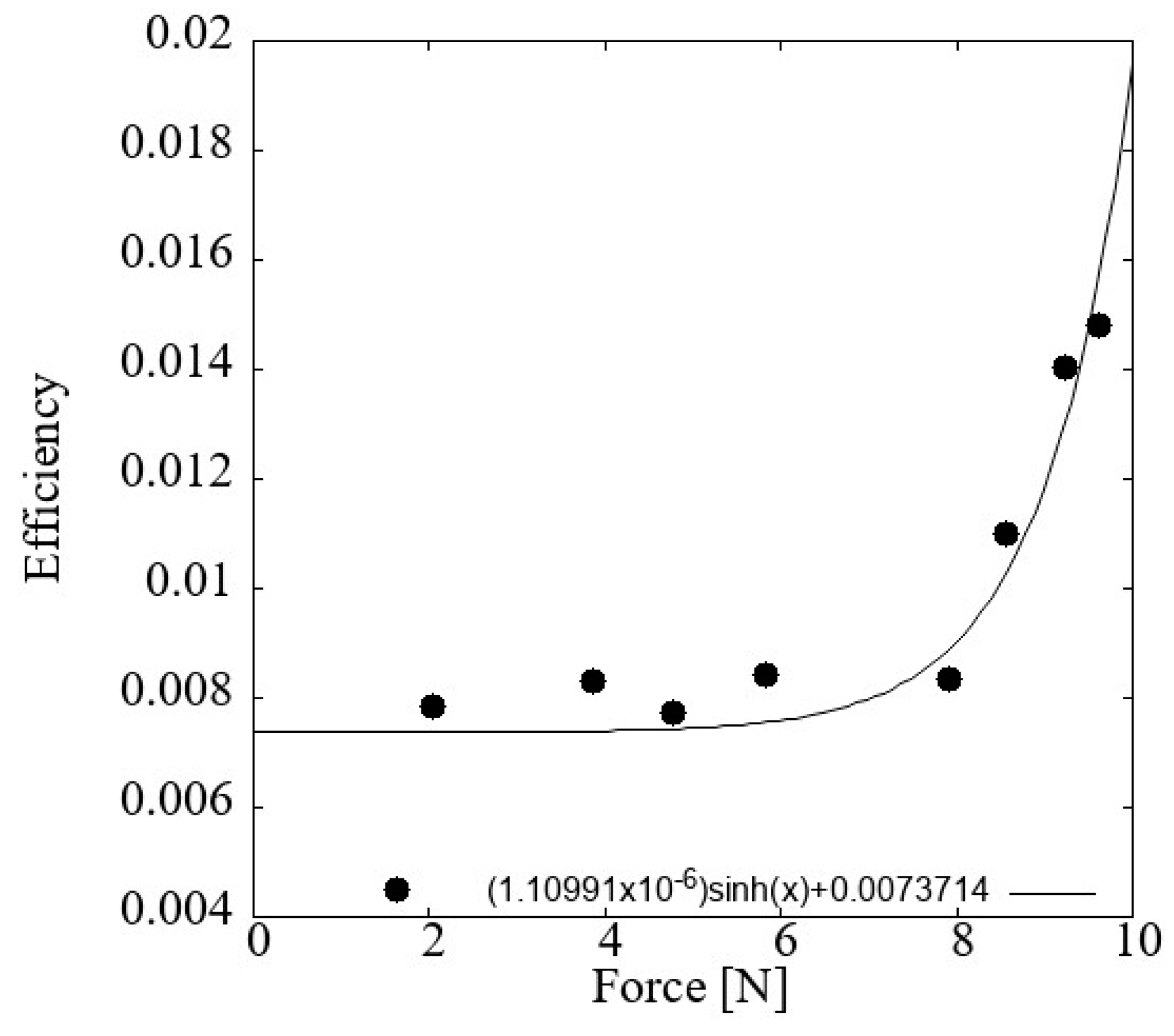
4.1. System Efficiency

A fundamental parameter is the system’s efficiency when the pianist interacts with the keyboard, as shown in Figure 13. It can be observed that similar efficiency values exist within the force range of 2 to 8 N, which corresponds to the working range of forces in this study. From 8 to 10 N, the efficiency value grew according to the behavior of the hyperbolic function, which coincided with what we expected from Equation (3). Therefore, the greater the force, the more the voltage grew. The process began with the determination of the efficiency of the piezoelectric device, followed by the calculation of the overall system efficiency.
The efficiency of the piezoelectric device was calculated using Equation (3), where it was determined that 10% of the applied force was successfully transferred to the piezoelectric system as ε p i e z o   p i a n i s t = 0.0155 % .
The net efficiency of the system was then calculated, and the values V 2 C 2 = 1.1374   µ J and F d ƞ = 76.91   m J were substituted into Equation (3), which resulted in ε s y s t e m = 0.001478 % .
At this point, it was observed that the efficiency of the system reached a value of 0.0014%, which makes sense given the variety of losses found in both the piezoelectric and the pianist’s wrist. However, the performance and operation of the system remained viable for implementation.

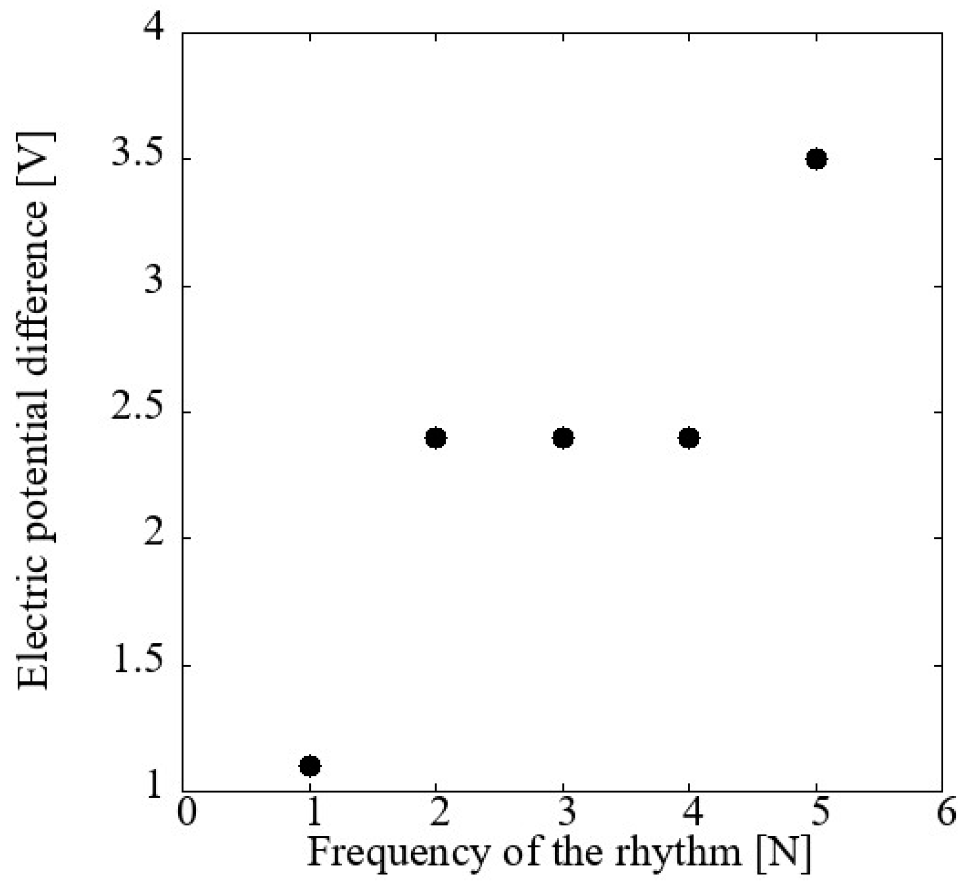
4.2. System Operation for Different Frequency Values

Since the system’s operation considers the time required to formulate a melody, the next test recorded the percentage of the sound volume and voltage generated by the pianist that played at five different frequencies: “Adagio” at 1 Hz; “Allegro” at 2 Hz; “Presto” at 3 Hz; “Prestissimo” at 4 Hz; and 5 Hz as the maximum, as it is a very high speed commonly used in electronic music [49]. The system operated at these frequencies for one minute.
It was observed that the percentage of the sound volume remained at 34.5% while maintaining the same force for each keystroke. Figure 14 shows the relationship between the voltage generation and the frequency increase. It was found that at higher frequencies, the piezoelectric device had less time to capture the transferred force, but the charge also accumulated more quickly. In the range of 2 Hz to 4 Hz, the piezoelectric device operated stably, where it maintained an average voltage parameter due to the capacitor and the piezoelectric characteristics. In addition, a large number of musical melodies fell within this frequency range.

4.3. Battery Charge

The system was implemented to recharge two pairs of Sony® NH-AA HR6 Mignon RB batteries (Sony Corporation, Tokyo, Japan) with the assistance of a pianist at a technical level using a single key on the organ. Considering that the standard number of beats per minute for pop music is 90 and for rock music is 120, a metronome was set at 100 beats per minute for 30 min for a total of two hours.
Thus, the pianist played 3000 notes for each battery, keeping the time intervals between each keystroke as precise as possible within the same force range to maintain a system voltage of 2.5 V. The batteries used were initially discharged until the organ could no longer be switched on. The system voltage values were recorded in Table 2, which corresponded to time zero. In addition, the moments of charge increase for each battery were marked.
Once the four batteries were recharged, they were placed in the musical organ, which allowed the instrument to remain operational for 53 s.
Finally, a test was conducted using an RB battery with the same specifications. This battery initially had a charge equivalent to 44 mV at its terminals. The system was used for 30 min, and its behavior was recorded every five minutes. Figure 15 presents this behavior. In this test, the same parameters were maintained as in the previous test, which allowed the charge increase in the RB to be observed as the pianist played the instrument.
When the rhythm is constant, the frequency can be calculated with the pulses per minute divided by 60 s.
Therefore, the frequency of 1.67 Hz is equivalent to 3000 pulses divided by 1800 s, which is equal to maintaining the rhythm of 100 pulses per minute.
To calculate the power generated, this information was substituted in Equation (4) to give 2.44   µ W .
Furthermore, resolving Equation (4) for I in order to obtain the current gave I = 0.97   µ A .
Once the generated power was obtained, along with the duration for which the organ remained operational with the recharged batteries, and knowing that the organ required 2.4 W per hour, consuming approximately 0.66 mW per second, excluding the startup consumption, it was possible to estimate the number of key presses the pianist must perform to charge the batteries for a specific duration of organ use by substituting into Equation (5), which gave 14,336 pulses.
It is important to highlight that when combining two or more keys to form musical chords, the voltages produced by the piezoelectric devices add up due to the difference in the response time of each piezoelectric. Additionally, melodies are not played continuously (one key at a time); there are also accompaniment chords, ranging from triad chords (three keys played simultaneously) to extended chords, which are commonly used in jazz music (four keys played with each hand simultaneously) [50]. Thus, when playing a different tetra-chord with each hand, the eight keys contribute voltage due to the piezoelectric configuration. Finally, it was observed that sliding the hand across all the keys resulted in an accumulated voltage that reached 14 V.

5. Discussion

The maximum transduction efficiency of the piezoelectric system was 0.001478%, and the voltage remained within the range where the RB was charged. With the generated energy, the organ remained powered for 53 s, and the four RBs were charged with 12,000 key presses, which was close to the estimated 14,336 key presses. The difference in the number of key presses was due to the additional energy consumed during the startup and the occasional increase in the force applied by the pianist. Finally, the RBs were not fully discharged; instead, they only failed to reach the minimum voltage required to power the keyboard. Additionally, a pianist needs to practice for several hours to master the instrument. Just practicing for a performance took more than 4 h in [51] and more than 33 h in [52]. The musical pieces presented consisted of a greater number of notes than simply playing one per second, meaning that these pianists could increase the voltage of the batteries without additional effort.
In Table 3, the results of energy harvesting projects were compared to highlight the possibility of integrating multiple piezoelectric devices as needed. Additionally, no other previous work utilized both hands in its application and the device was designed to operate in a modular fashion.

6. Conclusions

In this work, the structure of a piezoelectric system applied to a portable musical organ was presented. A commercially available piezoelectric model was selected to meet the specific requirements of a portable keyboard, such as the limited space and movement. A mathematical model was developed to relate the transformation of energy from the pianist to the piezoelectric device, and the system’s efficiency was calculated. Subsequently, the system was designed and validated in prototype form. In the first stage of testing, the system was characterized using a combination of masses, and the calculated efficiency was 0.014% with a voltage of 4.2 V in the piezoelectric device. Later, considering the mechanical resistance of the key and limited movement, the efficiency reached a value of 0.0148%, nearly three times lower, demonstrating the effect of the keys’ resistance. In the prototype, the LMMS software was used to relate the force applied by the pianist to the volume, and on this basis, the efficiency of the prototype was determined to be 0.0155%, a value close to the calculated one. Additionally, it was also found that only 10% of the energy applied to the key reached the sensor. Once the system was validated, the battery-charging process was carried out. In this test, the pianist interacted with a constant frequency and force, and only one key was used at a time. Four batteries were charged, and the overall efficiency of the system reached a value of 0.001478%. With the stored energy, the portable keyboard was able to stay on and operate for 53 s, confirming the system’s effectiveness and its ability to generate energy from everyday movements. Based on the formulation and the system, improvements can be made, such as developing a custom flexible piezoelectric device, that could improve the durability of the system by making it more resistant to knocks and falls, unlike ceramic piezoelectric devices, which can break if they are twisted. In the same way, using lead-free ceramic piezoelectric devices would make the system more environmentally friendly, eliminating the risk of improperly managed waste. The system’s energy conversion efficiency could be improved by using more efficient piezoelectric devices and introducing a new electronic configuration to increase the system’s efficiency, making it potentially autonomous. Considering the operation, the next step is to consider a combination of keys and an increase in the frequency, which is the most realistic option for keyboard operation.

Author Contributions

Conceptualization, J.E.V.-Á., G.A.A.-R. and J.J.R.-G.; methodology, G.A.A.-R. and J.O.-M.; performed prototype experiments validation, J.E.V.-Á., R.G.-V. and H.A.-R.; investigation, J.O.-M., G.G.E.-B. and H.A.-R.; writing—original draft preparation, J.E.V.-Á., G.A.A.-R. and G.G.E.-B. All authors have read and agreed to the published version of the manuscript.

Funding

This research received no external funding.

Data Availability Statement

The original contributions presented in this study are included in this article. Further inquiries can be directed to the corresponding author.

Acknowledgments

The authors thank the UCEMICH (Universidad de la Cienega del estado de Michoacán de Ocampo) for supporting our research and projects, which led to the writing of the present paper.

Conflicts of Interest

The authors declare no conflicts of interest.

Abbreviations

The following abbreviations are used in this manuscript:
RBRechargeable battery
LMMSLinux multimedia studio
PVDFPolyvinylidene fluoride or polyvinylidene difluoride
MIDIMusical Instrument Digital Interface

References

  1. Ruda, M.; Bubela, T.; Kiselychnyk, M.; Boyko, O.; Trishch, R.; Kolach, T. Study of the life cycle of the elemental composition of batteries. In Proceedings of the 2022 IEEE 16th International Conference on Advanced Trends in Radioelectronics, Telecommunications and Computer Engineering (TCSET), Lviv-Slavske, Ukraine, 22–26 February 2022; IEEE: Piscataway, NJ, USA, 2022. [Google Scholar] [CrossRef]
  2. dos Santos, K.O.; Guimarães Aniceto Silva, N.; Henrique Gonçalves Reis, O.; de Paula Almeida, J.V.; Galindo de Oliveira, G. Management of toxic waste released by incorrectly discarded batteries in Brazil. Chem. Teach. Int. 2024, 6, 121–125. [Google Scholar] [CrossRef]
  3. Hamade, R.; Ayache, R.A.; Ghanem, M.B.; Masri, S.E.; Ammouri, A. Life cycle analysis of AA alkaline batteries. Procedia Manuf. 2020, 43, 415–422. [Google Scholar] [CrossRef]
  4. Covaci, C.; Gontean, A. Piezoelectric energy harvesting solutions: A review. Sensors 2020, 20, 3512. [Google Scholar] [CrossRef]
  5. Harb, A. Energy harvesting: State-of-the-art. Renew. Energy 2011, 36, 2641–2654. [Google Scholar] [CrossRef]
  6. Liu, Y.; Khanbareh, H.; Halim, M.A.; Feeney, A.; Zhang, X.; Heidari, H.; Ghannam, R. Piezoelectric energy harvesting for self-powered wearable upper limb applications. Nano Sel. 2021, 2, 1459–1479. [Google Scholar] [CrossRef]
  7. Chou, X.; Zhu, J.; Qian, S.; Niu, X.; Qian, J.; Hou, X.; Mu, J.; Geng, W.; Cho, J.; He, J.; et al. All-in-one filler-elastomer-based high-performance stretchable piezoelectric nanogenerator for kinetic energy harvesting and self-powered motion monitoring. Nano Energy 2018, 53, 550–558. [Google Scholar] [CrossRef]
  8. Li, R.; Yu, Y.; Zhou, B.; Guo, Q.; Li, M.; Pei, J. Harvesting energy from pavement based on piezoelectric effects: Fabrication and electric properties of piezoelectric vibrator. J. Renew. Sustain. Energy 2018, 10, 054701. [Google Scholar] [CrossRef]
  9. Moure, A.; Rodríguez, M.I.; Rueda, S.H.; Gonzalo, A.; Rubio-Marcos, F.; Cuadros, D.U.; Pérez-Lepe, A.; Fernández, J.F. Feasible integration in asphalt of piezoelectric cymbals for vibration energy harvesting. Energy Convers. Manag. 2016, 112, 246–253. [Google Scholar] [CrossRef]
  10. Karimi, M.; Karimi, A.H.; Tikani, R.; Ziaei-Rad, S. Experimental and theoretical investigations on piezoelectric-based energy harvesting from bridge vibrations under travelling vehicles. Int. J. Mech. Sci. 2016, 119, 1–11. [Google Scholar] [CrossRef]
  11. del Castillo-García, G.; Blanco-Fernandez, E.; Pascual-Muñoz, P.; Castro-Fresno, D. Energy harvesting from vehicular traffic over speed bumps: A review. Proc. Inst. Civ. Eng.-Energy 2018, 171, 58–69. [Google Scholar] [CrossRef]
  12. Sezer, N.; Koç, M. A comprehensive review on the state-of-the-art of piezoelectric energy harvesting. Nano Energy 2021, 80, 105567. [Google Scholar] [CrossRef]
  13. Lund, A.; Rundqvist, K.; Nilsson, E.; Yu, L.; Hagström, B.; Müller, C. Energy harvesting textiles for a rainy day: Woven piezoelectrics based on melt-spun PVDF microfibres with a conducting core. NPJ Flex. Electron. 2018, 2, 9. [Google Scholar] [CrossRef]
  14. Taylor, G.W.; Burns, J.R.; Kammann, S.A.; Powers, W.B.; Welsh, T.R. The Energy Harvesting Eel: A small subsurface ocean/river power generator. IEEE J. Ocean. Eng. 2001, 26, 539–547. [Google Scholar] [CrossRef]
  15. Orrego, S.; Shoele, K.; Ruas, A.; Doran, K.; Caggiano, B.; Mittal, R.; Kang, S.H. Harvesting ambient wind energy with an inverted piezoelectric flag. Appl. Energy 2017, 194, 212–222. [Google Scholar] [CrossRef]
  16. Puscasu, O.; Counsell, N.; Herfatmanesh, M.R.; Peace, R.; Patsavellas, J.; Day, R. Powering lights with piezoelectric energy-harvesting floors. Energy Technol. 2018, 6, 906–916. [Google Scholar] [CrossRef]
  17. Riaz, A.; Sarker, M.R.; Saad, M.H.M.; Mohamed, R. Review on comparison of different energy storage technologies used in micro-energy harvesting, wsns, low-cost microelectronic devices: Challenges and recommendations. Sensors 2021, 21, 5041. [Google Scholar] [CrossRef]
  18. Khaliq, A.; Sheeraz, M.; Ullah, A.; Seog, H.J.; Ahn, C.W.; Kim, T.H.; Cho, S.; Kim, I.W. Ferroelectric seeds-induced phase evolution and large electrostrain under reduced poling field in bismuth-based composites. Ceram. Int. 2018, 44, 13278–13285. [Google Scholar] [CrossRef]
  19. Surmenev, R.A.; Orlova, T.; Chernozem, R.V.; Ivanova, A.A.; Bartasyte, A.; Mathur, S.; Surmeneva, M.A. Hybrid lead-free polymer-based nanocomposites with improved piezoelectric response for biomedical energy-harvesting applications: A review. Nano Energy 2019, 62, 475–506, Accedido el 25 de marzo de 2025. [En línea]. [Google Scholar] [CrossRef]
  20. Zheng, Q.; Shi, B.; Li, Z.; Wang, Z.L. Recent progress on piezoelectric and triboelectric energy harvesters in biomedical systems. Adv. Sci. 2017, 4, 1700029. [Google Scholar] [CrossRef]
  21. Heidenreich, P.A.; Trogdon, J.G.; Khavjou, O.A.; Butler, J.; Dracup, K.; Ezekowitz, M.D.; Finkelstein, E.A.; Hong, Y.; Johnston, S.C.; Khera, A.; et al. Forecasting the future of cardiovascular disease in the united states. Circulation 2011, 123, 933–944. [Google Scholar] [CrossRef]
  22. Meng, K.; Chen, J.; Li, X.; Wu, Y.; Fan, W.; Zhou, Z.; He, Q.; Wang, X.; Fan, X.; Zhang, Y.; et al. Flexible weaving constructed self-powered pressure sensor enabling continuous diagnosis of cardiovascular disease and measurement of cuffless blood pressure. Adv. Funct. Mater. 2018, 29, 1806388. [Google Scholar] [CrossRef]
  23. He, Z.; Gao, B.; Li, T.; Liao, J.; Liu, B.; Liu, X.; Wang, C.; Feng, Z.; Gu, Z. Piezoelectric-Driven self-powered patterned electrochromic supercapacitor for human motion energy harvesting. ACS Sustain. Chem. Eng. 2018, 7, 1745–1752. [Google Scholar] [CrossRef]
  24. Ben Ammar, M.B.; Sahnoun, S.; Fakhfakh, A.; Viehweger, C.; Kanoun, O. Self-Powered synchronized switching interface circuit for piezoelectric footstep energy harvesting. Sensors 2023, 23, 1830. [Google Scholar] [CrossRef]
  25. Maria Joseph Raj, N.P.; Alluri, N.R.; Vivekananthan, V.; Chandrasekhar, A.; Khandelwal, G.; Kim, S.-J. Sustainable yarn type-piezoelectric energy harvester as an eco-friendly, cost-effective battery-free breath sensor. Appl. Energy 2018, 228, 1767–1776. [Google Scholar] [CrossRef]
  26. Chinachatchawarat, T.; Pattarapongsakorn, T.; Ploypray, P.; Jintanawan, T.; Phanomchoeng, G. Optimizing piezoelectric bimorphs for energy harvesting from body motion: Finger movement in computer mouse clicking. Energies 2024, 17, 4121. [Google Scholar] [CrossRef]
  27. Tang, W.; Tian, J.; Zheng, Q.; Yan, L.; Wang, J.; Li, Z.; Wang, Z.L. Implantable Self-Powered Low-Level Laser Cure System for Mouse Embryonic Osteoblasts’ Proliferation and Differentiation. ACS Nano 2015, 9, 7867–7873. [Google Scholar] [CrossRef]
  28. Zheng, Q.; Shi, B.; Fan, F.; Wang, X.; Yan, L.; Yuan, W.; Wang, S.; Liu, H.; Li, Z.; Wang, Z.L. In Vivo Powering of Pacemaker by Breathing-Driven Implanted Triboelectric Nanogenerator. Adv. Mater. 2014, 26, 5851–5856. [Google Scholar] [CrossRef]
  29. Lai, Z.; Wang, S.; Zhu, L.; Zhang, G.; Wang, J.; Yang, K.; Yurchenko, D. A hybrid piezo-dielectric wind energy harvester for high-performance vortex-induced vibration energy harvesting. Mech. Syst. Signal Process. 2021, 150, 107212. [Google Scholar] [CrossRef]
  30. Lallart, M.; Cottinet, P.J.; Lebrun, L.; Guiffard, B.; Guyomar, D. Evaluation of energy harvesting performance of electrostrictive polymer and carbon-filled terpolymer composites. J. Appl. Phys. 2010, 108, 034901. [Google Scholar] [CrossRef]
  31. Wang, J.; Ma, L.; He, J.; Yao, Y.; Zhu, X.; Peng, L.; Yang, J.; Li, K.; Qu, M. Superwettable hybrid dielectric based multimodal triboelectric nanogenerator with superior durability and efficiency for biomechanical energy and hydropower harvesting. Chem. Eng. J. 2022, 431, 134002. [Google Scholar] [CrossRef]
  32. George, A.; Varghese, H.; Chandran, A.; Surendran, K.P.; Gowd, B. Directional freezing-induced self-poled piezoelectric nylon 11 aerogels as high-performance mechanical energy harvesters. J. Mater. Chem. A 2023, 12, 911–922. [Google Scholar] [CrossRef]
  33. Xu, T.-B.; Siochi, E.J.; Kang, J.H.; Zuo, L.; Zhou, W.; Tang, X.; Jiang, X. A piezoelectric PZT ceramic multilayer stack for energy harvesting under dynamic forces. In Proceedings of the ASME 2011 International Design Engineering Technical Conferences and Computers and Information in Engineering Conference, ASMEDC, Washington, DC, USA, 28–31 August 2011. [Google Scholar] [CrossRef]
  34. Yang, W.; Yao, F.; Zhou, Y. Voltage ripple suppression methods for the capacitor in modular multilevel converter submodules employing a reversed pulse width modulation-switching channel. Electronics 2022, 11, 2193. [Google Scholar] [CrossRef]
  35. Yaqoob, U.; Habibur, R.M.; Sheeraz, M.; Kim, H.C. Realization of self-poled, high performance, flexible piezoelectric energy harvester by employing PDMS-rGO as sandwich layer between P(VDF-TrFE)-PMN-PT composite sheets. Compos. Part B Eng. 2019, 159, 259–268. [Google Scholar] [CrossRef]
  36. Pîrvu, C.I.; Sover, A.; Abrudeanu, M. Participation of polymer materials in the structure of piezoelectric composites. Polymers 2024, 16, 3603. [Google Scholar] [CrossRef]
  37. Cédric, L.; Anis, K.; Sophie, B.; Frédéric, G. Piezoelectric polymer characterization setup for active energy harvesting. Polym. Adv. Technol. 2025, 36, e70056. [Google Scholar] [CrossRef]
  38. Lee, S.; Lim, Y. Generating Power Enhancement of Flexible PVDF Generator by Incorporation of CNTs and Surface Treatment of PEDOT:PSS Electrodes. Macromol. Mater. Eng. 2018, 303, 1700588. [Google Scholar] [CrossRef]
  39. Manna, S.; Nandi, A.K. Piezoelectric β Polymorph in Poly(vinylidene fluoride)-Functionalized Multiwalled Carbon Nanotube Nanocomposite Films. J. Phys. Chem. C 2007, 111, 14670–14680. [Google Scholar] [CrossRef]
  40. Thakur, P.; Kool, A.; Hoque, N.A.; Bagchi, B.; Khatun, F.; Biswas, P.; Brahma, D.; Roy, S.; Banerjee, S.; Das, S. Superior performances of in situ synthesized ZnO/PVDF thin film based self-poled piezoelectric nanogenerator and self-charged photo-power bank with high durability. Nano Energy 2018, 44, 456–467. [Google Scholar] [CrossRef]
  41. Dutta, B.; Kar, E.; Bose, N.; Mukherjee, S. NiO@SiO2/PVDF: A Flexible Polymer Nanocomposite for a High Performance Human Body Motion-Based Energy Harvester and Tactile e-Skin Mechanosensor. ACS Sustain. Chem. Eng. 2018, 6, 10505–10516. [Google Scholar] [CrossRef]
  42. Habibur, R.M.; Yaqoob, U.; Muhammad, S.; Uddin, A.I.; Kim, H.C. The effect of RGO on dielectric and energy harvesting properties of P(VDF-TrFE) matrix by optimizing electroactive β phase without traditional polling process. Mater. Chem. Phys. 2018, 215, 46–55. [Google Scholar] [CrossRef]
  43. Gino, M.E.; Selleri, G.; Cocchi, D.; Brugo, T.M.; Testoni, N.; De Marchi, L.; Zucchelli, A.; Fabiani, D.; Focarete, M.L. On the design of a piezoelectric self-sensing smart composite laminate. Mater. Des. 2022, 219, 110783. [Google Scholar] [CrossRef]
  44. Timmermans, S.; Dehez, B.; Fisette, P. Multibody-Based piano action: Validation of a haptic key. Machines 2020, 8, 76. [Google Scholar] [CrossRef]
  45. Samia, A.; Mohammed, E.-G.; Yoen, M.; Jean-Christophe, T.; Raynald, S. Mechanical characterization of a piezoelectric sensor for podiatrist applications. In Proceedings of the 2022 IEEE International Systems Conference (SysCon), Montreal, QC, Canada, 25–28 April 2022; pp. 1–5. [Google Scholar] [CrossRef]
  46. Harding, D.C.; Brandt, K.D.; Hillberry, B.M. Finger joint force minimization in pianists using optimization techniques. J. Biomech. 1993, 26, 1403–1412. [Google Scholar] [CrossRef]
  47. Turner, C.; Visentin, P.; Oye, D.; Rathwell, S.; Shan, G. Pursuing artful movement science in music performance: Single subject motor analysis with two elite pianists. Percept. Mot. Ski. 2021, 128, 1252–1274. [Google Scholar] [CrossRef]
  48. Gordon, E.E. An approach to the quantitative study of dynamics. J. Res. Music. Educ. 1960, 8, 23–30. [Google Scholar] [CrossRef]
  49. Tase, A.; Tase, A.; Dumitrache, M.; Calina, F.C.; Stanciulescu, L.; Stoiculescu, A. Could piano music therapy alleviate high sinus rhythm in subjects with controlled hypertension? Eur. Heart J. 2024, 45 (Supp. S1), ehae666-2953. [Google Scholar] [CrossRef]
  50. Bowling, D.L.; Purves, D.; Gill, K.Z. Vocal similarity predicts the relative attraction of musical chords. Proc. Natl. Acad. Sci. USA 2017, 115, 216–221. [Google Scholar] [CrossRef]
  51. Chaffin, R. Learning clair de lune: Retrieval practice and expert memorization. Music. Percept. 2007, 24, 377–393. [Google Scholar] [CrossRef]
  52. Chaffin, R.; Imreh, G.; Lemieux, A.F.; Chen, C. Seeing the big picture: Piano practice as expert problem solving. Music. Percept. 2003, 20, 465–490. [Google Scholar] [CrossRef]
Figure 1. Implementation diagram.
Energies 18 01850 g001
Figure 2. Electronic module for piezoelectric implementation in a portable musical organ.
Energies 18 01850 g002
Figure 3. Modular diagram of the proposed circuit for battery charging.
Energies 18 01850 g003
Figure 4. muRata® 7BB-35-3L0 piezoelectric device.
Energies 18 01850 g004
Figure 5. Masses one and six on a balance used for characterization: (a) mass one with a weight of 60 g; (b) mass six with a weight of 360 g.
Energies 18 01850 g005
Figure 6. Masses under gravity acceleration for characterization: (a) frontal view; (b) lateral view.
Energies 18 01850 g006
Figure 7. Generated voltage based on response of different forces generated for each of eight masses.
Energies 18 01850 g007
Figure 8. Electrical work obtained from the mechanical work supplied to the system.
Energies 18 01850 g008
Figure 9. Efficiency of the piezoelectric system depending on the applied force.
Energies 18 01850 g009
Figure 10. Percent of volume generated by each of the masses when dropped onto the key under gravitational acceleration.
Energies 18 01850 g010
Figure 11. Relationship between the percent of sound volume and the force exerted by the pianist, and the comparison with the relationship between the percent of sound volume and the force exerted by the masses.
Energies 18 01850 g011
Figure 12. Relationship between the percent of sound volume and the voltage generated by the pianist that played at different strength levels.
Energies 18 01850 g012
Figure 13. System efficiency ratio vs. pianist strength.
Energies 18 01850 g013
Figure 14. Graph of the voltage generated versus the frequency of the pianist.
Energies 18 01850 g014
Figure 15. Voltage increases of an AA RB while the pianist played for 30 min.
Energies 18 01850 g015
Table 1. Relationship between the forces exerted by the pianist vs. those measured by the Pololu® force-sensitive resistor model 2727 sensor.
MatizSound Volume
(%)
Resultant Force
(N)
Sensor
(N)
Force Comparison
(%)
Forte867.42290.73249.86%
Fortissimo918.07690.78459.71%
Fortississimo968.73090.84999.73%
Maximum999.12330.915210.03%
Table 2. Rechargeable battery voltages in volts through the time played by the pianist, moments of charge increase for each battery were marked.
MinutesRB 1RB 2RB 3RB 4
01.2261.2261.0041.004
51.2261.2261.0041.004
101.2271.2261.0051.004
151.2271.2271.0051.005
301.2271.2271.0051.005
Table 3. Piezoelectric device applications presented in literature as harvesting systems.
ReferenceType of MovementVmWKeyboard Implementation
This proposalSwipe hand over keyboard140.04606Yes
This proposalPress a key at 5 Hz with one finger3.50.01439Yes
[7]Stretch200.011No
[23]Impacts on the palm20.00018No
[24]Footsteps7.23.6No
[26]Press with finger5.50.34No
[13]Climbing stairs with a backpack40.004No
Disclaimer/Publisher’s Note: The statements, opinions and data contained in all publications are solely those of the individual author(s) and contributor(s) and not of MDPI and/or the editor(s). MDPI and/or the editor(s) disclaim responsibility for any injury to people or property resulting from any ideas, methods, instructions or products referred to in the content.

