Abstract
In the present study, a numerical simulation and optimization combined approach is applied to investigate the thermal performance of a solar air heater (SAH). Numerical simulation of the solar air heater is performed based on computational fluid dynamics (CFDs) via ANSYS Fluent 2023R1 software. The solar air heater includes a corrugated absorber plate with a Chevron-type design. Present study was conducted in Al-Kharj, Saudi Arabia on August 15. The optimization process is used to enhance the thermal efficiency of the solar system. In the optimization process, several geometric parameters of the solar air heater, including the wave height and pitch length of the corrugated absorber plate and the height of the airflow channel under the absorber plate, have been evaluated. The wave height is between 10 and 20 mm, the pitch length is between 50 and 90 mm, and the channel height is between 70 and 90 mm. Therefore, the design of experiment (DOE) and response surface methodology (RSM) are utilized to estimate temperature rise and thermal efficiency. The thermal analysis shows that increasing the wave height, decreasing the pitch length, and shortening the channel height enhances both the temperature rise coefficient and the thermal efficiency.
1. Introduction
In recent decades, the world has tended towards sustainable energy, caused by rising environmental concerns and finite fossil energy resources. So, utilizing renewable and sustainable energy has become a global necessity [1,2]. Compared to renewable energy sources, solar energy has become the leading choice because of its wide availability, freeness, and capability to be used in various applications [3,4]. Solar systems are one of the highly efficient ways to employ solar energy sources. For example, there are different solar collector designs, from flat plate to evacuated tube, parabolic compound to parabolic dish, etc. [5,6]. However, solar air heaters (SAHs) are known as one of the most widely used solar heating systems [7,8]. Due to their uncomplicated design, SAHs are cost-effective and widely popular as collection devices. These heat devices are utilized in various applications, from heating buildings to industrial processes [9,10]. There are different types of solar air heaters in diverse configurations. Solar air heaters are available in two design configurations: single-pass and double-pass systems [11,12]. They can be integrated with porous media or photovoltaic elements or used with concentrators or extended surfaces with different shapes. Also, they can include phase change materials (PCMs), packing beds, and coated absorption surfaces [13,14,15]. Numerous experimental studies have been carried out to analyze the solar heater operation. Several experimental tests were implemented and compared based on different design conditions and different operating conditions [16,17]. In addition, using computational fluid dynamics (CFDs) methods for the numerical simulation of solar heaters and thermal analysis of their systems has become popular among researchers. CFD is a simulation technology to predict the behavior of a solar air heater and reach an optimal design [18,19]. So, researchers have employed numerical modeling to analyze hydraulic and thermal behaviors within solar heating systems. In numerical methods, various factors, including system designs and dimensions, turbulence models, material properties, solar radiation, different thermal conditions, etc., are studied [20,21,22]. The absorber plate is a crucial component in the solar heater, which plays an essential role in solar energy absorption and heat transfer into the airflow inside the system. Absorber plates are designed in different configurations, and hence, different forms, shapes, and sizes of the absorber plates are analyzed [23,24]. For example, applying artificially roughened surfaces for absorber plates, such as transverse rectangular ribs, quarter-circle ribs, etc., can affect convective heat transfer and thermohydraulic performance. So, several studies have investigated the thermal behavior of the absorber plate on the system’s efficiency [25,26,27,28]. In recent studies, applying the corrugated absorber plates as an effective solution to raise the heat exchange and develop the thermal operation of solar heaters has attracted the attention of researchers. Corrugated absorber plates can accelerate the thermal exchange in the airflow channel, resulting in improved system efficiency. Different corrugation types on the absorber plates, such as V-corrugated, sinusoidal-corrugated, etc., have been studied [29,30,31]. In addition, other works have been conducted on Chevron designs in thermal systems due to generating turbulence and rising heat transmission. For example, thermal and hydraulic characteristics are analyzed in plate heat exchangers with the Chevron design [32,33]. In recent years, optimization studies have also played a crucial role in developing and progressing the operating efficiency of solar heating systems. Therefore, researchers have employed the design of experiments (DOEs) method to determine the most effective geometric factors for solar systems optimization. In some studies, like Reynolds [34,35], the thermal efficiency of solar heaters is optimized by evaluating several geometric parameters such as different artificial roughness elements or operating factors. Also, researchers have used the response surface methodology (RSM) to optimize thermal systems. In these studies, objective parameters such as thermal efficiency are investigated based on the values of the variable parameters by adopting the RSM technique [36,37]. After reviewing the procedure of numerous recent studies on solar air heaters, it is motivating to integrate different design ideas to achieve an attractive idea. So, in the present CFD work, the initiative was taken to model a solar air heater containing an absorber plate of a Chevron type mounted with a corrugated design on the air channel. Then, it was decided to focus on dimensional analysis in the design of the solar air heater. The purpose of the present study is to optimize the design of a solar air heater to significantly increase the thermal efficiency of its system.
2. Methodology
2.1. Geometry Definition
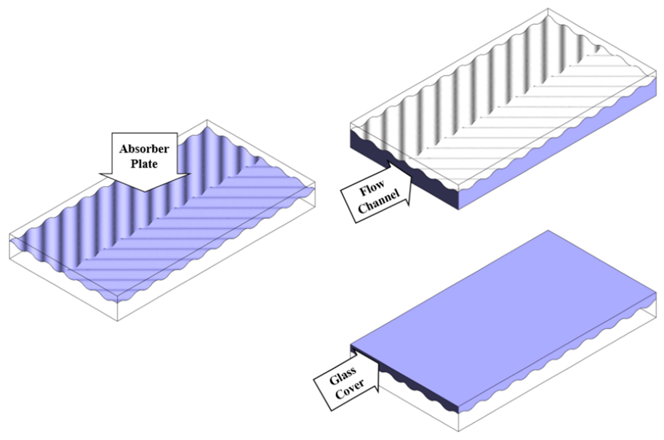
The solar air heater is modeled as shown in Figure 1. The overall dimensions of this heater are 60 cm and 110 cm. The solar air heater contains an absorber plate between the airflow channel and the glass cover. The absorber plate of the heater is a corrugated type; it consists of a Chevron design.

Figure 1.
View of Geometry.
2.2. CFD Methodology
In this CFD study, the numerical simulation of a solar air heater is performed via ANSYS Fluent 2023R1 software [38]. In the solar heater system, radiation heat transfer is significant. Therefore, the discrete ordinates (DO) radiation model is used. The present project was implemented in Al-Kharj city at 12:00 on 15 August. So, the solar ray tracing model was applied. Therefore, the solar radiation intensity is 897.9 w/m2.
2.2.1. Materials
The absorber plate of the solar air heater is aluminum material, and a glass cover is on it. Table 1 describes the characteristics of materials utilized in solar heaters.

Table 1.
Properties of the materials.
The characteristics of air are dependent on the air bulk temperature, Equations (1)–(3) [39].
2.2.2. Boundary Conditions
The airflow temperature is considered 307.15 K, which flows at 0.2 m/s velocity through the inlet, and a 0 Pascal pressure gauge is applied to the outlet. The turbulent intensity is 5%, and the turbulent viscosity ratio is 10. The absorber plate is defined as an opaque wall to absorb solar heat well. The absorptivity of the absorber plate is considered to be 0.8. The air channel walls (including the bottom and side walls) are assumed to be insulated. The glass cover is defined as a semi-transparent wall, while there is convection heat transfer with the surrounding environment.
2.2.3. Turbulence Model
The airflow becomes turbulent under the influence of the rough wave-shaped plate. The characteristic length is not constant due to the changing geometric dimensions of the air channel, so the Reynolds number varies from about 2440 to 3630. The renormalization group (RNG) k-ε turbulent model is applied to simulate the turbulence inside the air channel.
2.3. Governing Equations
General equations are solved for the airflow, including continuity, momentum, and energy, as presented in Equations (4)–(6) [40].
The continuity equation is as follows:
The momentum equation is as follows:
The energy equation is as follows:
The overall radiative transfer equation (RTE) at position r and direction s is presented according to Equation (7), where ω is the solid angle and I is the radiation intensity based on position (r) and direction (s).
In the present simulation, the discrete ordinates (DOs) model is used to solve the radiation equation for a finite number of discrete solid angles. Every solid angle is related to a vector direction (s) in the global Cartesian coordinate system. In other words, the DO radiation model converts Equation (7) into a transport equation for the radiation intensity in spatial coordinates (X, Y, Z), computing individual transport equations for every directional vector (s). Thus, the DO radiation model accounts for the radiative transfer equation as a field equation, according to Equation (8) [41].
Radiative heat transfer between surfaces is considered according to Equation (8). The absorber plate only absorbs and reflects radiation heat, while the cover glass allows radiation rays to pass through partially.
2.4. Performance Parameters
For the solar heater evaluation, the thermal parameters are studied, such as thermal efficiency and the temperature rise coefficient.
Thermal efficiency is measured by the ratio of usable heat absorption in the air into the incident solar energy on the absorber plate. The thermal efficiency of the solar heaters, useful heat gain, and incident solar radiation are computed according to Equations (9)–(11), respectively [42,43].
where mf is the mass flow rate, Tf is the temperature of the air, I is the solar radiation intensity, and Ap is the area surface of the absorber plate.
The temperature rise coefficient is a dimensionless parameter that indicates the ratio of temperature gain to the inlet air temperature (according to Equation (12)) [43].
2.5. Grid Study
The unstructured mesh is applied to the model domain. A view of the mesh is shown in Figure 2.
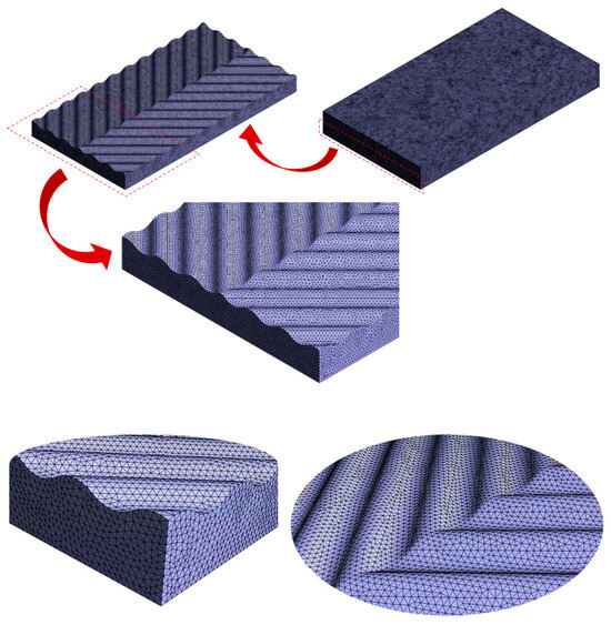
Figure 2.
View of mesh.
The grid independence process is implemented based on air temperature at the channel outlet. For this, calculations are run in the cases with different cell numbers. As shown in Table 2, the mesh becomes independent in the 1,500,000-element case.
Table 2.
Grid independence tests.
3. Validation
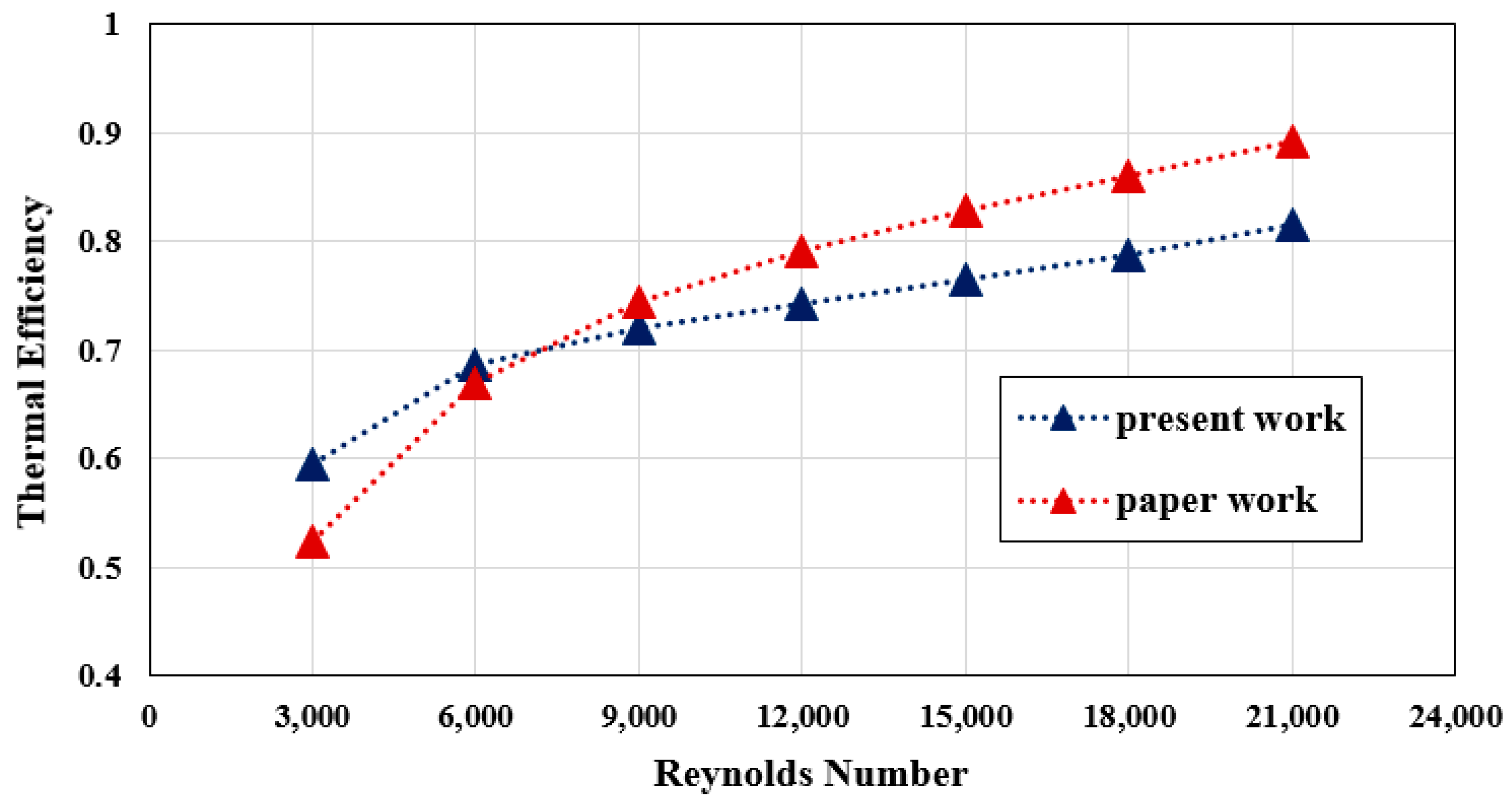
A study by [39] has investigated the performance of a solar air heater. In the mentioned study, a solar air heater having a circular perforated absorber plate is analyzed. CFD analysis has been conducted on the solar heater utilizing the DO radiation model and solar ray tracing approach. Different case studies have been investigated based on the number of vents and the diameter of the vents. So, a numerical simulation was performed based on one of the case studies (having 24 vents with 8 mm diameter) in the reference article by [39]. Then, the results obtained from the present numerical work are compared with the reference article based on thermal efficiency. The comparison of the results of the present work with the results of the article is shown in Figure 3 and Table 3.
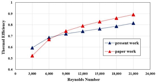
Figure 3.
Comparison between present study and reference paper [39].
Table 3.
Comparison between present study and reference paper [39].
4. Results and Discussion
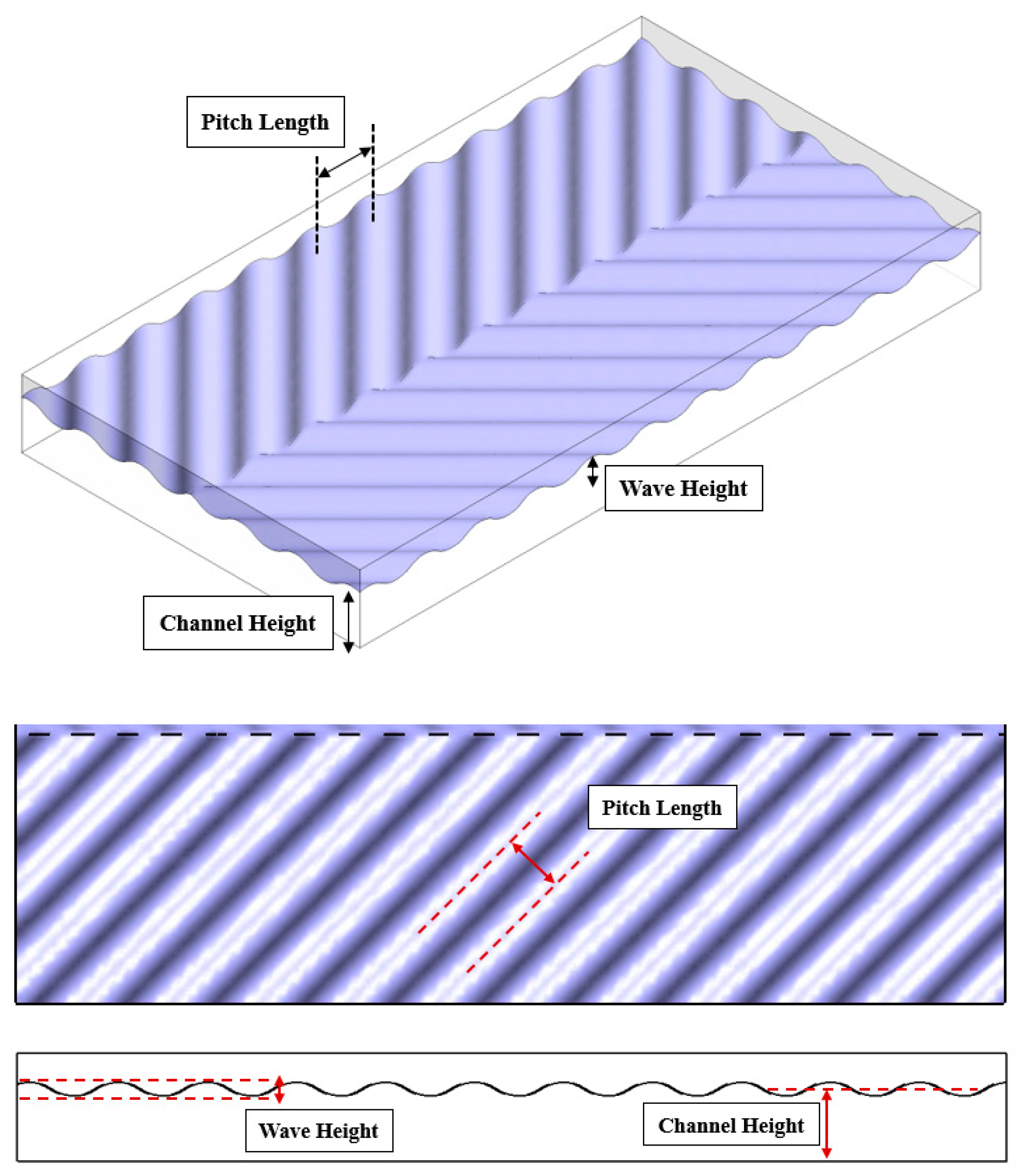
In this CFD work, the effects of three geometric parameters on thermal performance have been studied. These input parameters include the wave height of the corrugated absorber plate, the pitch length of the corrugated absorber plate, and the height of the channel under the absorber plate, which are shown in Figure 4. It is assumed that the wave height is 10 to 20 mm, the pitch length is 50 to 90 mm, and the channel height is 70 to 90 mm.
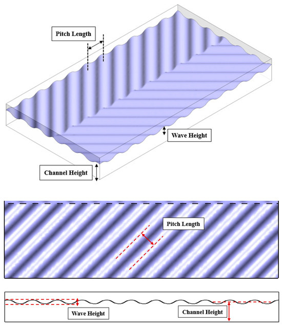
Figure 4.
View of geometric parameters.
4.1. Thermal Analysis
Figure 5 shows the temperature distribution on the absorber plate at different wave heights. In these cases, the pitch length and the flow channel height are assumed to be constant. The results show that in the lower wave height, the absorber plate has a higher temperature. In other words, when the wave height is higher, air flow under the absorber plate inside the channel becomes more turbulent. As a result, the absorber plate has more heat transfer with the airflow inside the channel, and as a consequence, the temperature of the absorber decreases.
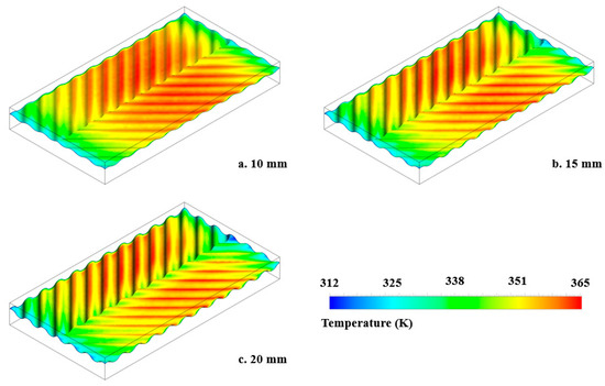
Figure 5.
Contours of temperature on absorber plate. (a) Wave height = 10 mm, (b) wave height = 15 mm, (c) wave height = 20 mm.
Figure 6 shows the temperature distribution on the absorber plate in different pitch lengths. In these cases, the wave height and the flow channel height are assumed to be constant. The results show that in the higher pitch length, the absorber plate has a higher temperature. In other words, when the pitch length is lower, air flow under the absorber plate inside the channel becomes more turbulent. As a result, the absorber plate has more heat transfer with the airflow inside the channel, and as a consequence, the temperature of the absorber decreases.
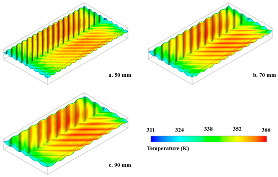
Figure 6.
Contours of temperature on absorber plate. (a) Pitch length = 50 mm, (b) pitch length = 70 mm, (c) pitch length = 90 mm.
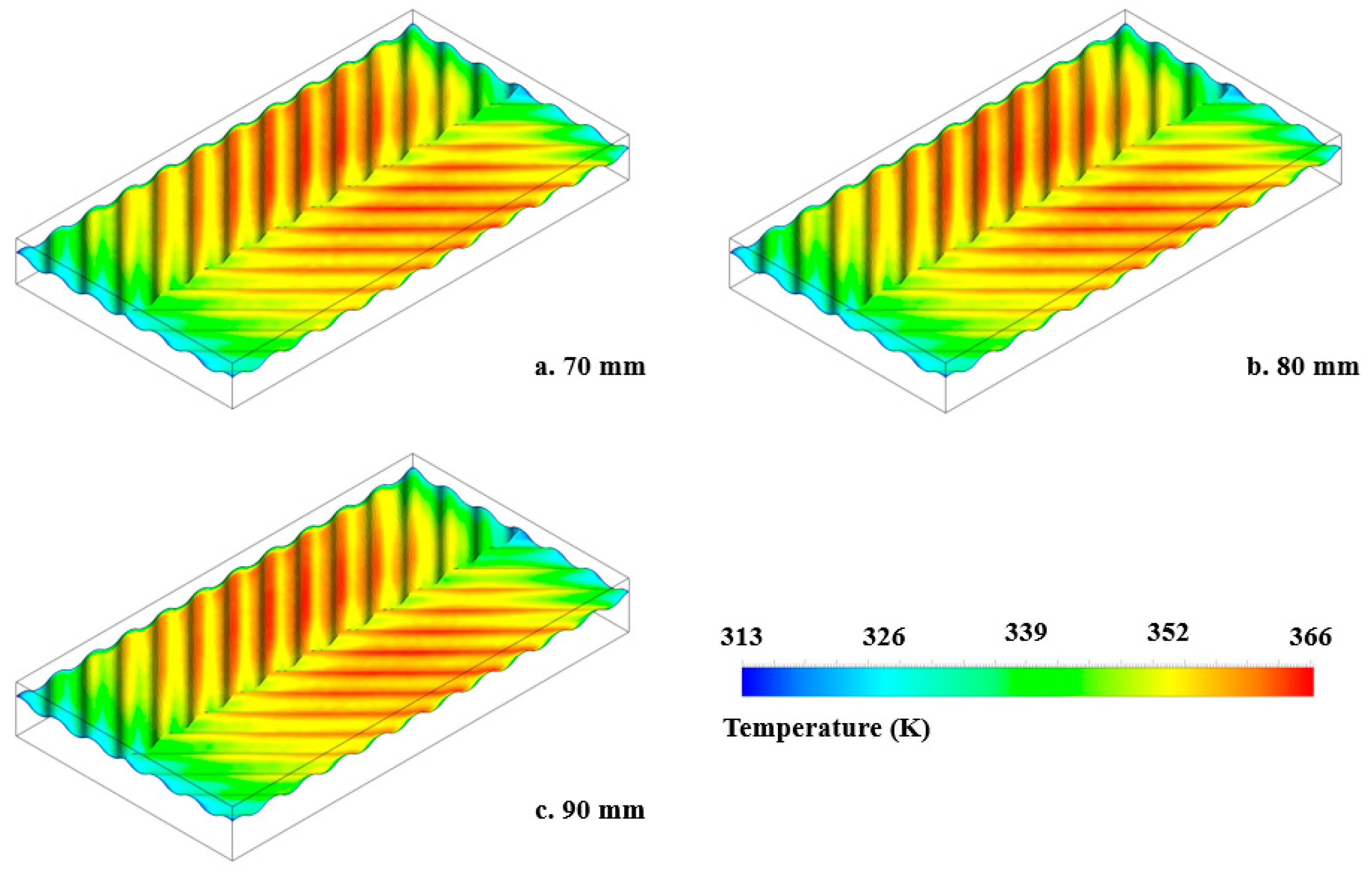
Figure 7 shows the temperature distribution on the absorber plate in different heights of the flow channels. In these cases, the wave height and the pitch length are assumed to be constant. This means that the plate absorber has a constant effect on the airflow turbulence. Therefore, the results show that the influence of the channel height on the temperature of the absorber plate isn’t considerable.

Figure 7.
Contours of temperature on absorber plate. (a) Channel height = 70 mm, (b) channel height = 80 mm, (c) channel height = 90 mm.
4.2. Optimization
After independent analysis of the input parameters, including wave height, pitch length, and channel height, the simultaneous analysis of them is investigated. The present work aims to achieve the best value for each input parameter to obtain the optimal design state. Therefore, the optimization process has been conducted using ANSYS Workbench 2023R1 software.
First, the design of experiment (DOE) tool is used to provide several design points. These design points are a set of sample values according to the range variation of three input parameters (wave height, pitch length, and channel height). In the present work, 15 design points are produced based on the central composite design (CCD) algorithm [44,45]. The central composite design (CCD) is utilized to optimize thermal performance in solar air heaters because this method allows for investigating parametric interactions with fewer experiments and has better predictive capabilities for modeling the behavior of complex thermal systems. Then, the output parameters are obtained at each of the design points. These output parameters include the temperature rise coefficient of the air and the thermal efficiency of the solar heater. These design points are shown in Table 4.
Table 4.
Design points in the design of experiments (DOEs).
Next, the response surface methodology (RSM) is used to estimate the value of the output parameters (i.e., temperature rise coefficient and thermal efficiency) in the entire range of input parameters [44,45]. In other words, RSM obtains the output values in the entire range based on the output values of each sample design point. In the present work, RSM operates based on the genetic aggregation algorithm. This algorithm is the most common method used in optimization processes.
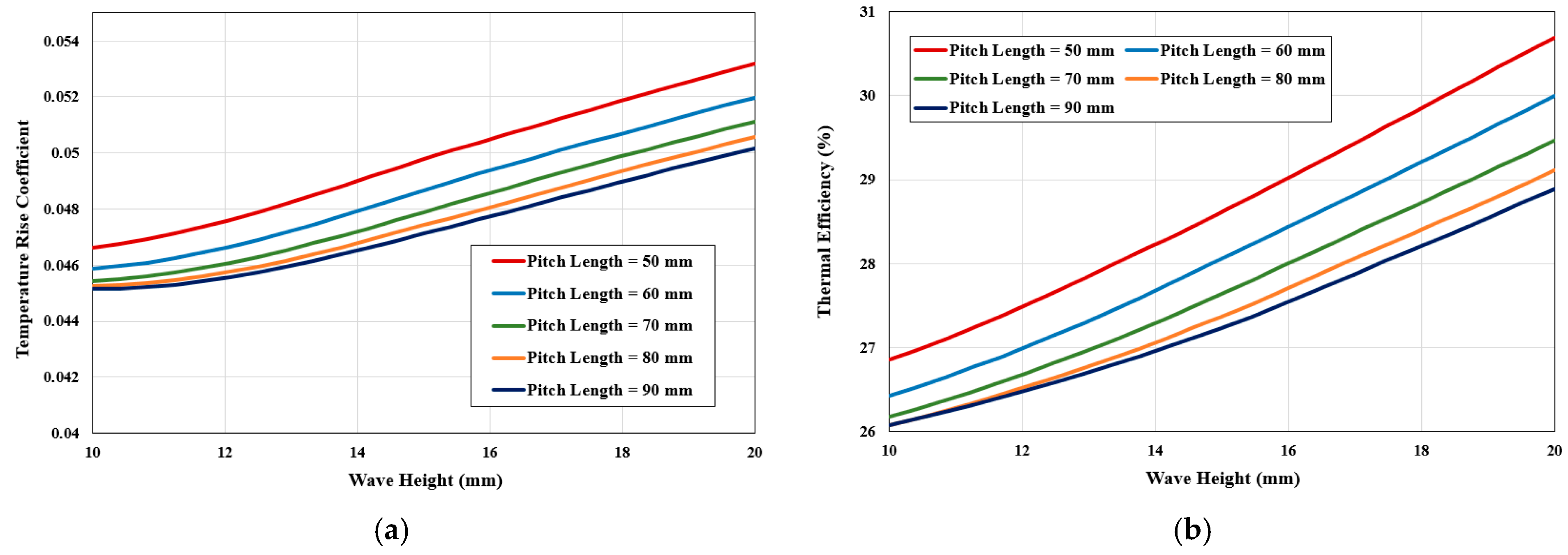
Figure 8 shows 2D plots of temperature rise coefficient variation and thermal efficiency variation based on the wave height for different pitch lengths. Figure 8 shows that the lower the pitch length, the higher the temperature rise coefficient and thermal efficiency. Also, the wave height increase causes an increase in the temperature rise coefficient and thermal efficiency in the entire range of the pitch lengths. This is because increasing the wave height and decreasing the pitch length causes the airflow inside the channel to have more opportunity for heat transfer due to promoting mixing in greater contact with the absorber plate. So, by increasing wave height at a low pitch length, the temperature rise reaches up to 0.0532 and the thermal efficiency up to 30.69%.
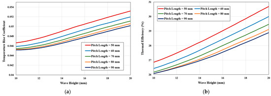
Figure 8.
2D plot based on wave height and pitch length. (a) Temperature rise coefficient, (b) thermal efficiency.
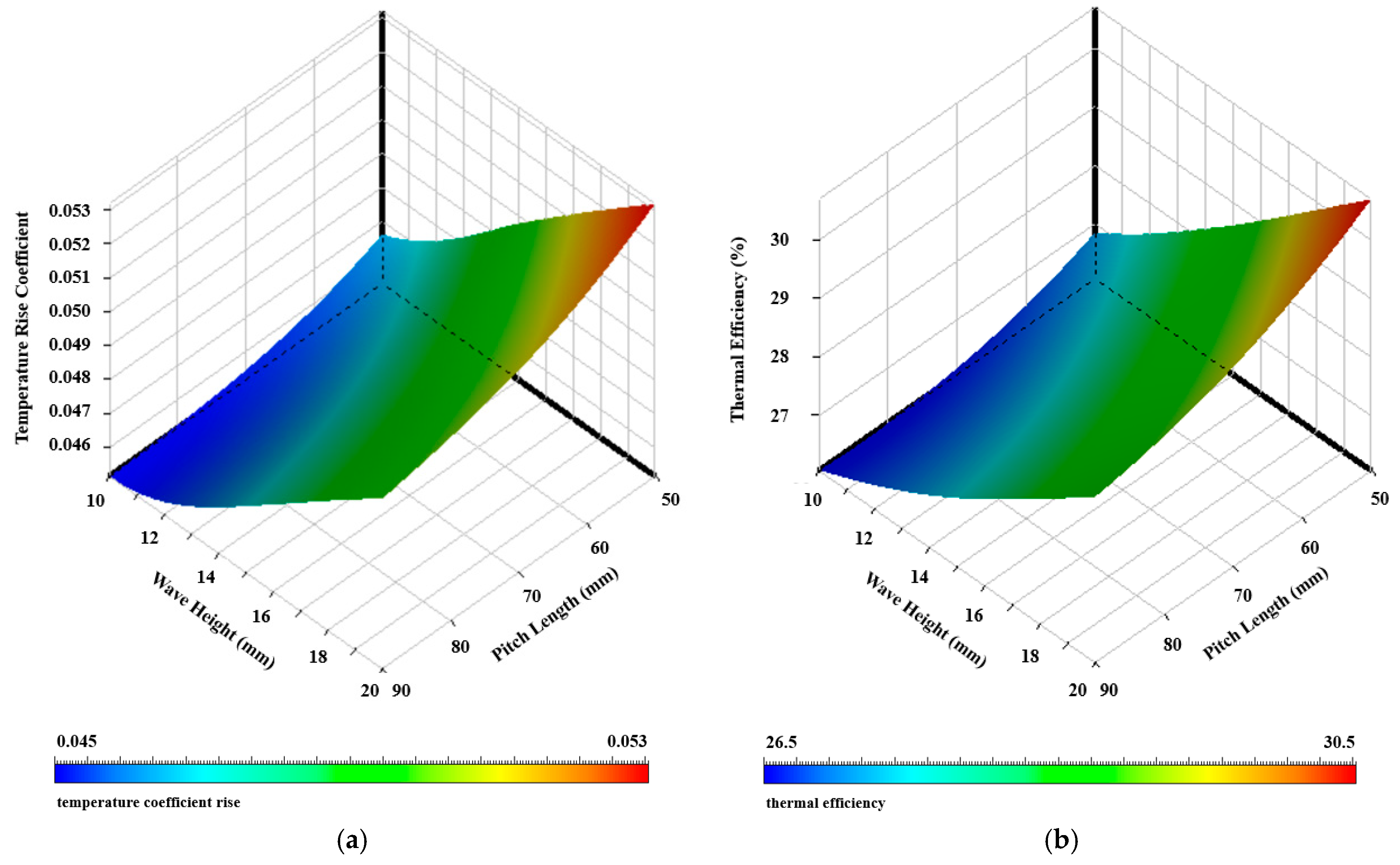
Figure 9 shows the 3D plots of the variation in the temperature rise coefficient and thermal efficiency based on the wave height and pitch length, respectively. Figure 9 confirms that increasing the wave height and decreasing the pitch length lead to an air temperature increase and thermal efficiency augment.

Figure 9.
3D plot based on wave height and pitch length. (a) Temperature rise coefficient, (b) thermal efficiency.
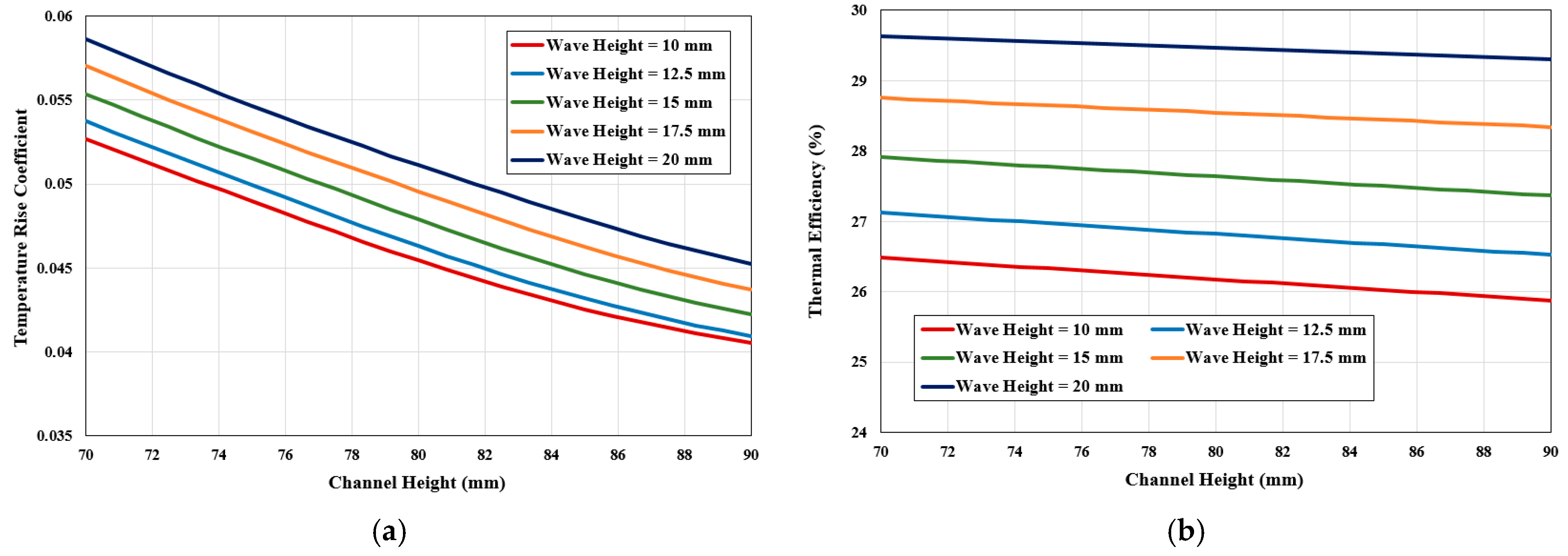
Figure 10 shows 2D plots of temperature rise coefficient variation and thermal efficiency variation based on the channel height for different wave heights. Figure 10 shows that the higher the wave height, the higher the temperature rise coefficient and thermal efficiency. Also, the channel height increase causes a decrease in the temperature rise coefficient and thermal efficiency in the entire range of the wave heights. This is because by shortening the channel height and, as a consequence, decreasing the size of the interior of the channel, heat distribution in the air is formed rapidly. So, by increasing the channel height at a low wave height, the temperature rise drops to 0.0405 and the thermal efficiency to 25.88%.
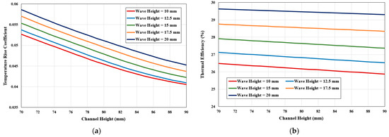
Figure 10.
2D plot based on wave height and channel height. (a) Temperature rise coefficient, (b) thermal efficiency.
Figure 11 shows the 3D plots of variation of the temperature rise coefficient and thermal efficiency based on the wave height and channel height, respectively. Figure 11 confirms that increasing the wave height and decreasing the channel height leads to an air temperature increase and thermal efficiency augment.
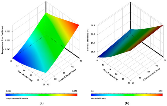
Figure 11.
3D plot based on wave height and channel height. (a) Temperature rise coefficient, (b) thermal efficiency.
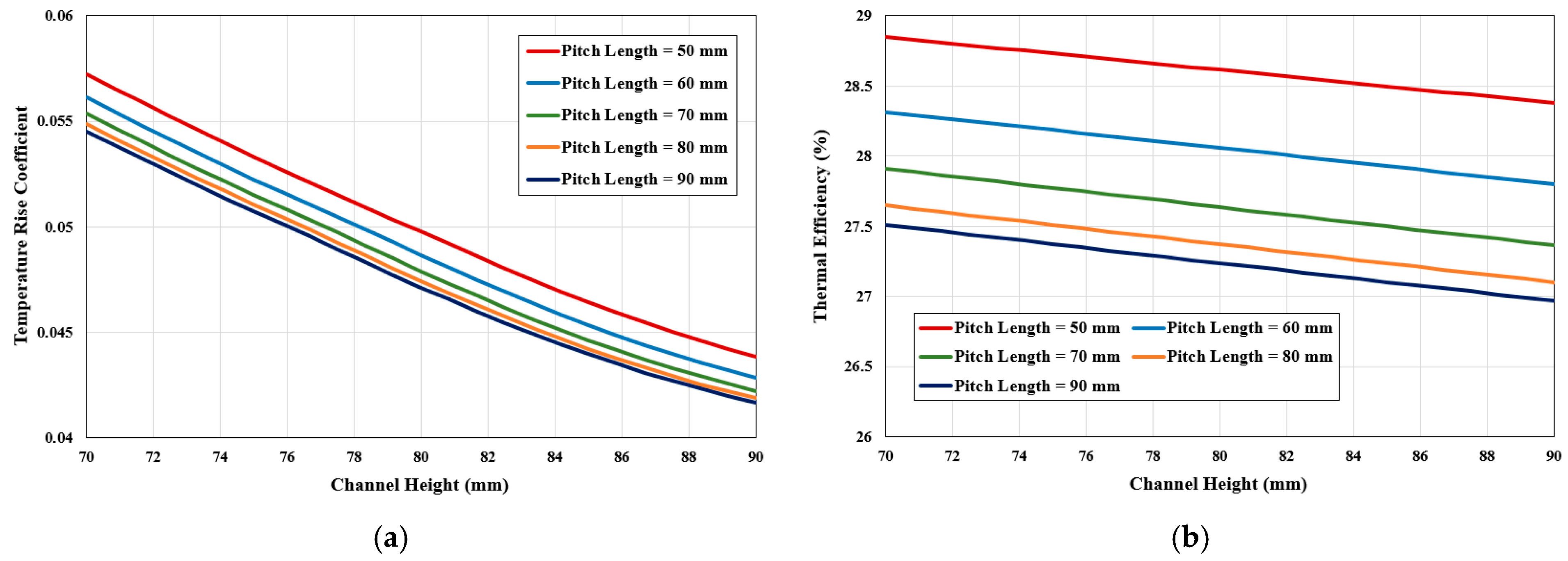
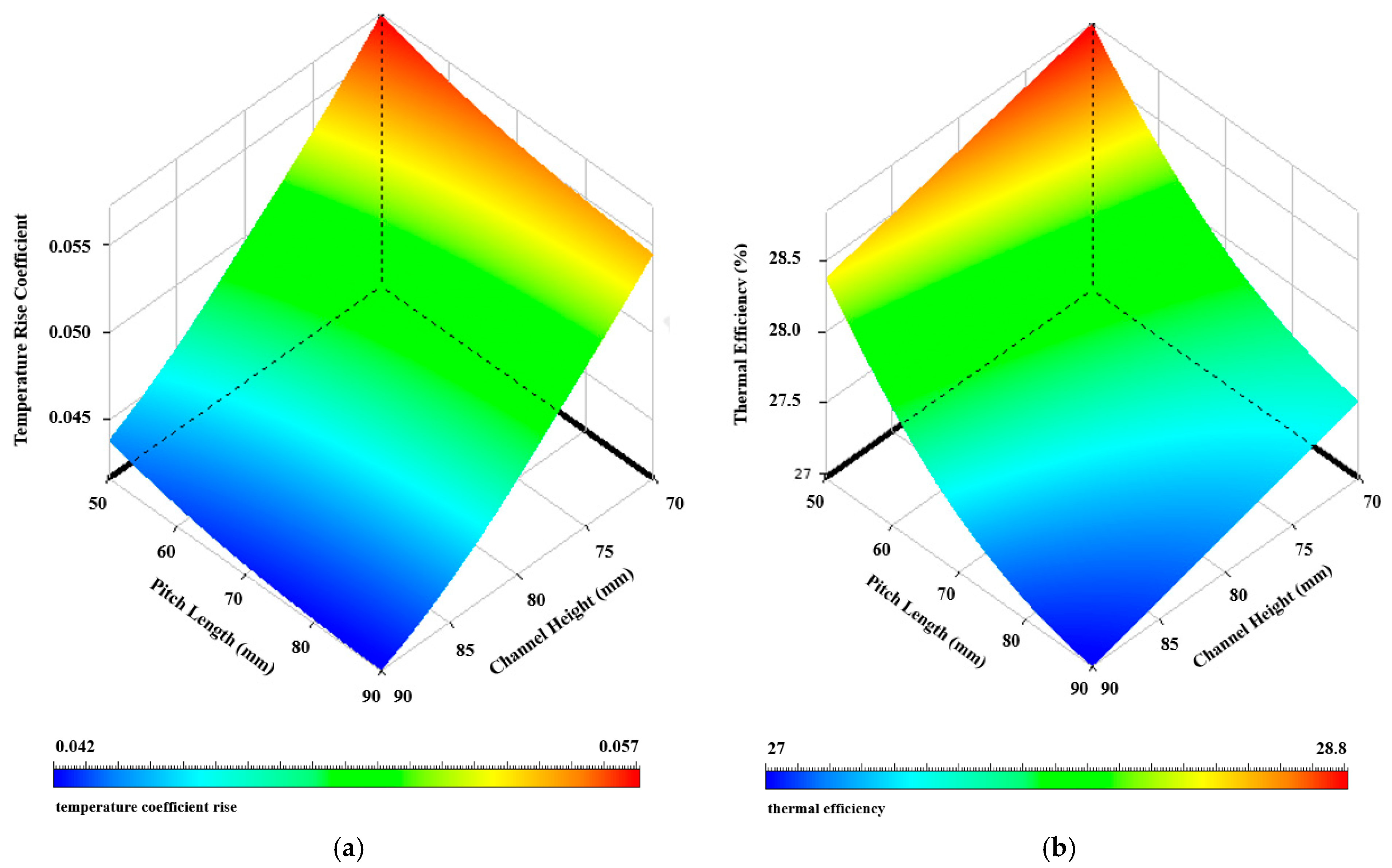
Figure 12 shows 2D plots of temperature rise coefficient variation and thermal efficiency variation based on the channel height for different pitch lengths. Figure 12 shows that the lower the pitch length, the higher the temperature rise coefficient and thermal efficiency. Also, the channel height increase causes a decrease in the temperature rise coefficient and thermal efficiency in the entire range of the pitch lengths. So, by decreasing channel height at a low pitch length, the temperature rise reaches up to 0.0572 and the thermal efficiency up to 28.84%.
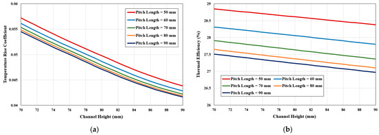
Figure 12.
A 2D plot based on pitch length and channel height. (a) Temperature rise coefficient, (b) thermal efficiency.
Figure 13 shows the 3D plots of variation in the temperature rise coefficient and thermal efficiency based on the pitch length and channel height, respectively. Figure 13 confirms that decreasing the pitch length and decreasing the channel height leads to an air temperature increase and thermal efficiency augment.

Figure 13.
3D plot based on pitch length and channel height. (a) Temperature rise coefficient, (b) thermal efficiency.
Input parameters, including wave height, pitch length, and channel height, have unequal effects on output parameters, including temperature rise coefficient and thermal efficiency. So, the dependence degree of the output parameters on each input parameter is analyzed. Figure 14 shows the influence of input parameters on output parameters as a plot of local sensitivity. According to the local sensitivity, the channel height has the most effect on the temperature rise coefficient, while the wave height has the most impact on the thermal efficiency. In other words, it can be concluded that the temperature rise coefficient is less dependent on wave height and pitch length, while thermal efficiency has less dependence on pitch length and channel height. In addition, the local sensitivity plot confirms that the temperature rise coefficient and thermal efficiency have a direct relation with the wave height and an inverse relation with the pitch length and channel height.
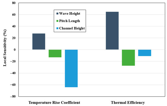
Figure 14.
Local sensitivity.
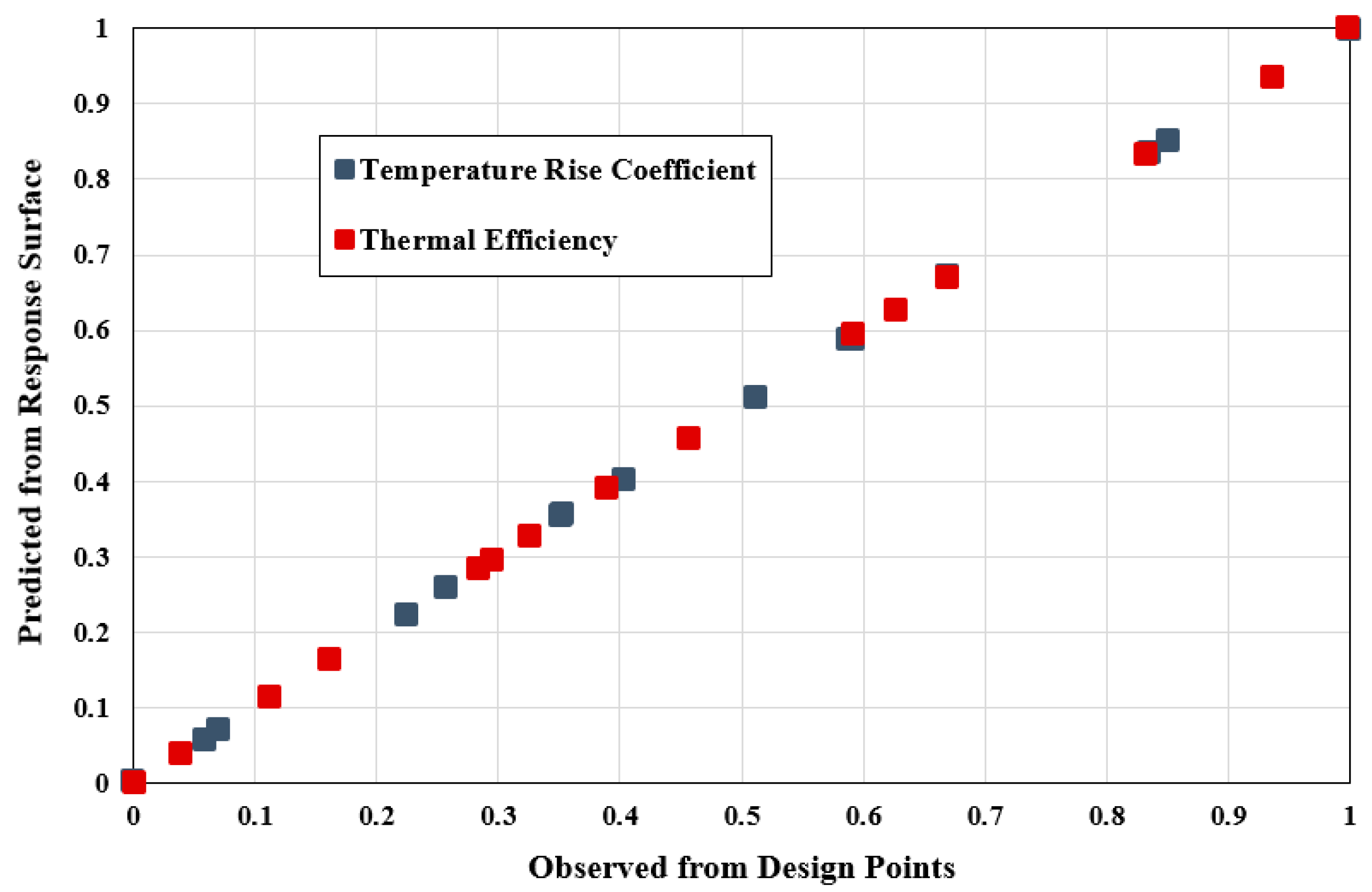
The accuracy of the RSM process is presented in Figure 15 as a goodness-of-fit plot. The goodness-of-fit plot shows how much the estimated values for the output parameters based on RSM match the values obtained from run calculations of different cases in the design points. According to this plot, it can be concluded that the values obtained from RSM have an acceptable accuracy.
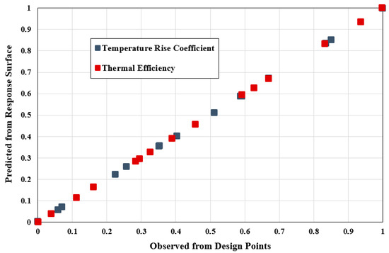
Figure 15.
Goodness of fit.
4.3. Pressure Analysis
Figure 16 shows the 3D plots of variation of the pressure drop based on the wave height, pitch length, and channel height. When the wave height increases and the pitch length decreases, the pressure drop augments because the roughness of the absorber plate rises, and more turbulence is generated in the airflow. However, when the channel height increases, the pressure drop decreases because the airflow passes more freely through the rough absorber in the channel.
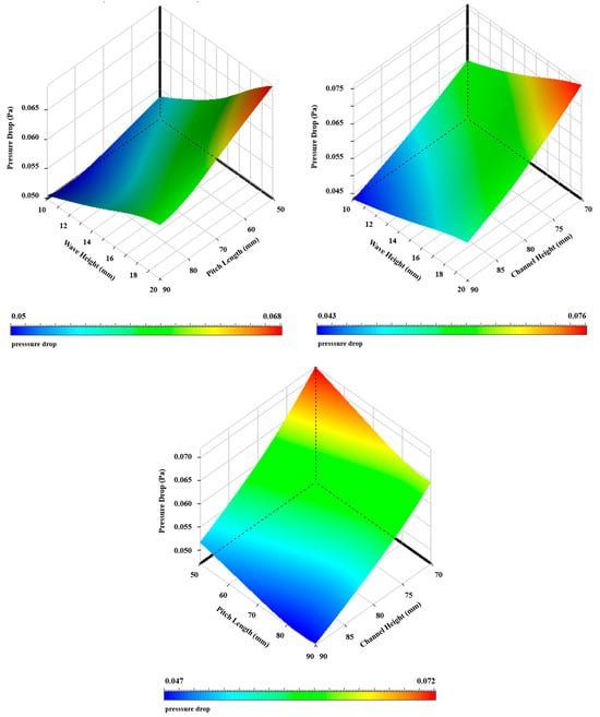
Figure 16.
3D plot of pressure drop based on wave height, pitch length, and channel height.
5. Conclusions
In this study, the influence of several geometric parameters on the thermal performance of a solar air heater has been investigated. In order to analyze the simultaneous influence of several geometric parameters on the temperature rise coefficient and thermal efficiency, an optimization process has been used. Therefore, by using the design of experiment (DOE) method, different cases have been run based on different values of input parameters. Then, by using response surface methodology (RSM), the output parameters were estimated for the entire range of input parameters. The results show that decreasing the channel height increases the temperature rise of the airflow inside the channel and augments the thermal efficiency of the solar system. In addition, enlarging the contact surface of the absorber plate due to the increasing wave height and reducing pitch length causes more heat transfer. So, it increases both the temperature rise of the airflow and the thermal efficiency of the system. Therefore, based on the optimization analysis, the optimal condition for the design of the solar air heater is obtained where the channel height of the airflow is 70 mm, the pitch length is 50 mm, and the wave height is 20 mm, which leads to a thermal efficiency equal to 30.841% and a temperature rise coefficient equal to 0.0608. In conclusion, this optimized design can be utilized in manufacturing solar air heaters, industrial and agricultural dryers, and building heating systems. Optimal design with appropriate geometric dimensions can lead to economic savings and reduced energy consumption compared to conventional designs.
Funding
This research received no external funding.
Data Availability Statement
The original contributions presented in this study are included in the article. Further inquiries can be directed to the corresponding author.
Acknowledgments
This study is supported via funding from Prince sattam bin Abdulaziz University project number (PSAU/2025/1446).
Conflicts of Interest
The author declares no conflict of interest.
Nomenclature
| Ap | area of absorber plate (m2) | r | direction vector |
| a | absorption coefficient | s | position vector |
| Bi | body force (N/m3) | T | air temperature (K) |
| Cpf | specific heat of air (J/kg.K) | Tfi | inlet air temperature (K) |
| Ct | temperature rise coefficient | Tfo | outlet air temperature (K) |
| e | specific internal energy (J/kg) | u, v, w | air velocity component (x,y,z) (m/s) |
| I | radiation intensity (W/m2) | ηth | thermal efficiency |
| k | thremal conductivity of air (W/mK) | μ | dynamic viscosity of air (kg/m.s) |
| ṁf | mass flow rate (kg/s) | ρ | air density (kg/m3) |
| n | refractive index | σs | scattering coefficient |
| P | pressure (Pa) | φ | phase function |
| Q̇c | incident solar radiation (W) | ω | solid angle (radians) |
| Q̇u | useful heat gained (W) |
References
- Panwar, N.L.; Kaushik, S.C.; Kothari, S. Role of renewable energy sources in environmental protection: A review. Renew. Sustain. Energy Rev. 2011, 15, 1513–1524. [Google Scholar] [CrossRef]
- Owusu, P.A.; Asumadu-Sarkodie, S. A review of renewable energy sources, sustainability issues and climate change mitigation. Cogent Eng. 2016, 3, 1167990. [Google Scholar] [CrossRef]
- Kannan, N.; Vakeesan, D. Solar energy for future world: A review. Renew. Sustain. Energy Rev. 2016, 62, 1092–1105. [Google Scholar] [CrossRef]
- Pourasl, H.H.; Barenji, R.V.; Khojastehnezhad, V.M. Solar energy status in the world: A comprehensive review. Energy Rep. 2023, 10, 3474–3493. [Google Scholar] [CrossRef]
- Kalogirou, S.A. Solar thermal collectors and applications. Prog. Energy Combust. Sci. 2004, 30, 231–295. [Google Scholar] [CrossRef]
- Mund, C.; Rathore, S.K.; Sahoo, R.K. A review of solar air collectors about various modifications for performance enhancement. Sol. Energy 2021, 228, 140–167. [Google Scholar] [CrossRef]
- Saxena, A.; El-Sebaii, A.A. A thermodynamic review of solar air heaters. Renew. Sustain. Energy Rev. 2015, 43, 863–890. [Google Scholar] [CrossRef]
- Almutairi, K.; Almutairi, M.; Harb, K.; Marey, O.; Aungkulanon, P. An updated review on solar air heating systems. Sustain. Energy Technol. Assess. 2022, 53, 102573. [Google Scholar] [CrossRef]
- Markam, B.; Maiti, S. Artificial enhancer for small-scale solar air heater-A comprehensive review. Clean. Energy Syst. 2023, 4, 100046. [Google Scholar] [CrossRef]
- Hegde, A.K.; Pai, R.; Karanth, K.V. Performance augmentation of solar air heaters: A comprehensive analysis. Sol. Energy 2023, 253, 527–553. [Google Scholar] [CrossRef]
- Shrivastava, V.; Yadav, A.S.; Shrivastava, N. Comparative Study of the Performance of Double-Pass and Single-Pass Solar Air Heater with Thermal Storage. In Proceedings of the International Conference on Recent Advancements in Mechanical Engineering, Silchar, India, 8–9 July 2020; Springer Nature: Singapore, 2021. [Google Scholar] [CrossRef]
- Mohamed Salih, M.M.; Alomar, O.R.; Aziz Ali, F. An experimental investigation of a double pass solar air heater performance: A comparison between natural and forced air circulation processes. Solar Energy 2019, 193, 184–194. [Google Scholar] [CrossRef]
- Kabeel, A.E.; Hamed, M.H.; Omara, Z.M.; Kandeal, A.W. Solar air heaters: Design configurations, improvement methods and applications, A detailed review. Renew. Sustain. Energy Rev. 2017, 70, 1189–1206. [Google Scholar] [CrossRef]
- Chamoli, S.; Chauhan, R.; Thakur, N.S.; Saini, J.S. A review of the performance of double pass solar air heater. Renew. Sustain. Energy Rev. 2012, 84, 285–307. [Google Scholar] [CrossRef]
- Parsa, H.; Saffar-Avval, M.; Hajmohammadi, M.R. Improvement of solar air heaters performance with PCM-filled baffles and storage bed. Mech. Sci. 2023, 260, 108629. [Google Scholar] [CrossRef]
- Omojaro, A.P.; Aldabbagh, L.B.Y. Experimental performance of single and double pass solar air heater with fins and steel wire mesh as absorber. Appl. Energy 2010, 87, 3759–3765. [Google Scholar] [CrossRef]
- Akpinar, E.K.; Koçyiğit, F. Energy and exergy analysis of a new flat-plate solar air heater having different obstacles on absorber plates. Appl. Energy 2010, 87, 3438–3450. [Google Scholar] [CrossRef]
- Potgieter, M.S.W.; Bester, C.R.; Bhamjee, M. Experimental and CFD investigation of a hybrid solar air heater. Sol. Energy 2020, 195, 413–428. [Google Scholar] [CrossRef]
- Singh, A.P.; Singh, O.P. Performance enhancement of a curved solar air heater using CFD. Sol. Energy 2018, 174, 556–569. [Google Scholar] [CrossRef]
- Yadav, A.S.; Bhagoria, J.L. Heat transfer and fluid flow analysis of solar air heater: A review of CFD approach. Renew. Sustain. Energy Rev. 2013, 23, 60–79. [Google Scholar] [CrossRef]
- Kumar, A.; Kim, M.H. CFD Analysis on the Thermal Hydraulic Performance of an SAH Duct with Multi V-Shape Roughened Ribs. Energies 2016, 9, 415. [Google Scholar] [CrossRef]
- Yusaidi, N.J.; Fauzan, M.F.; Abdullah, A.F.; Ibrahim, A.; Ishak, A.A. Theoretical and experimental investigations on the effect of double pass solar air heater with staggered-diamond shaped fins arrangement. Case Stud. Therm. Eng. 2024, 60, 104619. [Google Scholar] [CrossRef]
- Tanda, G. Performance of solar air heater ducts with different types of ribs on the absorber plate. Energy 2011, 36, 6651–6660. [Google Scholar] [CrossRef]
- Borah, P.P.; Pathak, K.K.; Gupta, A.; Roy, S.; Das, B. Experimental study of a solar air heater with modified absorber plate through square obstacles with threaded pin fins. Appl. Therm. Eng. 2023, 228, 120544. [Google Scholar] [CrossRef]
- Kumar, A.; Kim, M.-H. Thermohydraulic performance of rectangular ducts with different multiple V-rib roughness shapes: A comprehensive review and comparative study. Renew. Sustain. Energy Rev. 2016, 54, 635–652. [Google Scholar] [CrossRef]
- Bhushan, B.; Singh, R. A review on methodology of artificial roughness used in duct of solar air heaters. Energy 2010, 35, 202–212. [Google Scholar] [CrossRef]
- Boulemtafes-Boukadoum, A.; Benzaoui, A. CFD based Analysis of Heat Transfer Enhancement in Solar Air Heater Provided with Transverse Rectangular Ribs. Energy Procedia 2014, 50, 761–772. [Google Scholar] [CrossRef]
- Mahanand, Y.; Senapati, J.R. Thermo-hydraulic performance analysis of a solar air heater (SAH) with quarter-circular ribs on the absorber plate: A comparative study. Int. J. Therm. Sci. 2021, 161, 106747. [Google Scholar] [CrossRef]
- Karim, M.A.; Hawlader, M.N.A. Performance investigation of flat plate, v-corrugated and finned air collectors. Energy 2006, 31, 452–470. [Google Scholar] [CrossRef]
- Gao, W.; Lin, W.; Liu, T.; Xia, C. Analytical and experimental studies on the thermal performance of cross-corrugated and flat-plate solar air heaters. Appl. Energy 2007, 84, 425–441. [Google Scholar] [CrossRef]
- Yehualashet, K.N.; Fatoba, O.; Asfaw, S.M. Experimental study and numerical analysis of thermal performance of corrugated plate solar collector. Mater. Today Proc. 2022, 62, 2849–2856. [Google Scholar] [CrossRef]
- Dović, D.; Palm, B.; Švaić, S. Generalized correlations for predicting heat transfer and pressure drop in plate heat exchanger channels of arbitrary geometry. Int. J. Heat Mass Transf. 2009, 52, 4553–4563. [Google Scholar] [CrossRef]
- Ham, J.; Kim, E.; You, N.; Cho, H. Comparison of thermal performance in solution heat exchangers with different chevron angles in absorption system. Case Stud. Therm. Eng. 2023, 51, 103598. [Google Scholar] [CrossRef]
- Varun; Siddhartha. Thermal performance optimization of a flat plate solar air heater using genetic algorithm. Appl. Energy 2010, 87, 1793–1799. [Google Scholar] [CrossRef]
- Salarpour, N.; Azadani, L.N. Optimization and evaluation of thermo-hydraulic performance of solar air heaters equipped with different roughness geometries. Case Stud. Therm. Eng. 2024, 61, 105037. [Google Scholar] [CrossRef]
- Mohammed, N.A.; Alwared, A.I.; Shakhir, K.S.; Sulaiman, F.A. Synthesis, characterization of FeNi3@SiO2@CuS for enhance solar photocatalytic degradation of atrazine herbicides: Application of RSM. Results Surf. Interfaces 2024, 16, 100253. [Google Scholar] [CrossRef]
- Matheswaran, M.M.; Arjunan, T.V.; Muthusamy, S.; Natrayan, L.; Panchal, H.; Subramaniam, S.; Khedkar, N.K.; El-Shafay, A.S.; Sonawane, C. A case study on thermo-hydraulic performance of jet plate solar air heater using response surface methodology. Case Stud. Therm. Eng. 2022, 34, 101983. [Google Scholar] [CrossRef]
- ANSYS Inc. ANSYS Fluent 2023 R1, Theory Guide; ANSYS Inc.: Canonsburg, PA, USA, 2023. [Google Scholar]
- Shetty, S.P.; Madhwesh, N.; Vasudeva Karanth, K.V. Numerical analysis of a solar air heater with circular perforated absorber plate. Sol. Energy 2021, 215, 416–433. [Google Scholar] [CrossRef]
- Manjunath, M.S.; Vasudeva Karanth, K.; Yagnesh Sharma, N. Numerical Analysis of the Influence of Spherical Turbulence Generators on Heat Transfer Enhancement of Flat Plate Solar Air Heater. Energy 2017, 121, 616–630. [Google Scholar] [CrossRef]
- Arunkumar, H.S.; Kumar, S.; Vasudeva Karanth, K. Energy exergy and economic analysis of a multiple inlet solar air heater for augmented thermohydraulic performance. Therm. Eng. 2024, 246, 122981. [Google Scholar] [CrossRef]
- Ghritlahre, H.K.; Verma, M.; Parihar, J.S.; Mondloe, D.S.; Agrawal, S. A detailed review of various types of solar air heaters performance. Sol. Energy 2022, 237, 173–195. [Google Scholar] [CrossRef]
- Arunkumar, H.S.; Kumar, S.; Vasudeva Karanth, K. Experimental study on thermo-hydraulic performance of a solar air heater with rectangular perforated duct inserts. Sol. Energy 2021, 227, 179–189. [Google Scholar] [CrossRef]
- Korpale, V.S.; Deshmukh, S.P.; Mathpati, C.S.; Dalvi, V.H. Numerical simulations and optimization of solar air heaters. Therm. Eng. 2020, 180, 115744. [Google Scholar] [CrossRef]
- Qader, B.S.; Supeni, E.E.; Ariffin, M.K.A.; Abu Talib, A.R. RSM approach for modeling and optimization of designing parameters for inclined fins of solar air heater. Renew. Energy 2019, 136, 48–68. [Google Scholar] [CrossRef]


Disclaimer/Publisher’s Note: The statements, opinions and data contained in all publications are solely those of the individual author(s) and contributor(s) and not of MDPI and/or the editor(s). MDPI and/or the editor(s) disclaim responsibility for any injury to people or property resulting from any ideas, methods, instructions or products referred to in the content. |
© 2025 by the author. Licensee MDPI, Basel, Switzerland. This article is an open access article distributed under the terms and conditions of the Creative Commons Attribution (CC BY) license (https://creativecommons.org/licenses/by/4.0/).