Article

A Combined LPTN-FETM Approach for Dual-Mode Thermal Analysis of Composite Cage Rotor Bearingless Induction Motor (CCR-BIM) with Experimental Verification

1
School of Electrical and Photoelectric Engineering, West Anhui University, Lu’An 237012, China
2
School of Electrical and Information Engineering, Jiangsu University, Zhenjiang 212013, China
*
Author to whom correspondence should be addressed.
Energies 2025, 18(7), 1816; https://doi.org/10.3390/en18071816
Submission received: 25 February 2025 / Revised: 29 March 2025 / Accepted: 1 April 2025 / Published: 3 April 2025
(This article belongs to the Section F: Electrical Engineering)

Abstract

:
This paper proposes a dual-mode thermal analysis framework for the composite cage rotor bearingless induction motor (CCR-BIM), which combines lumped parameter thermal network (LPTN) and finite element thermal model (FETM) methods with experimental verification. The CCR-BIM, an advanced motor design combining torque and suspension windings within a single stator core, offers significant advantages in high-speed and high-precision applications. However, accurate thermal management remains a critical challenge due to its complex structure and increased losses. An LPTN model tailored to the unique thermal characteristics of the CCR-BIM is proposed, and detailed FETM simulations and experimental tests are validated. The LPTN model employs a meshing method to discretize the motor into orthogonal thermal nodes, enabling the rapid and accurate calculation of steady-state temperatures. The FETM further verifies the LPTN results by simulating the transient and steady-state temperature fields. Experimental validation using a 2 kW CCR-BIM test platform confirms the effectiveness of both models, with temperature predictions closely matching measured values. This study provides a reliable thermal analysis method for CCR-BIM.

1. Introduction

Bearingless induction motors (BIMs) have emerged as critical components in high-speed precision applications due to their non-contact operation and reduced maintenance costs [1,2,3,4]. The composite cage rotor bearingless induction motor (CCR-BIM) is an improved motor obtained by designing the rotor structure based on BIM [5]. Compared with the rotor structure of traditional BIMs, the composite rotor adds the solid layer of the outer rotor, and the squirrel cage rotor of the inner rotor has also been redesigned. Because the motor winding adopts the double stator winding structure and the existence of rotor solid layer, the loss of the CCR-BIM will increase, and the temperature will also increase. The rise in temperature will change the impedance and electromagnetic path of each component of the CCR-BIM, which will affect the driving and the suspension performance. Therefore, the thermal analysis and fast thermal calculation of the CCR-BIM have important research value for motor performance analysis. It is also of great significance to study the temperature rise distribution law of the windings and rotors in the motor for motor protection and fault diagnosis. For the study of motor temperature, the development of modern numerical methods and computer technology provides powerful tools for studying temperature fields. At present, the lumped parameter thermal network (LPTN) method and the finite element thermal model (FETM) method have become the hot application methods of motor thermal analysis research [6,7]. The LPTN model is a method to analyze the thermal field through the network topology of the motor by applying the principle of graph theory. The physical laws that followed have a similar relationship to the circuit network, and the temperature of each part of the motor can be calculated. The key to the research of the LPTN method is to find the heat source of the motor and accurately divide the thermal circuit based on the LPTN [8]. The FETM has good boundary adaptability and high calculation accuracy and can obtain the motor temperature field distribution and any hot spot location [9]. Scholars have performed a lot of research on the thermal analysis of various motors using these two methods. In the study of [10], the LPTN and the FETM method are used to calculate the temperature distribution of the conical rotor motor, and the results are verified by the experimental platform. In the study of [11], an LPTN equation is proposed for the multi-layer switched reluctance motor applied in electric vehicles and confirmed by the FETM method and experiments. In the study of [12], the LPTN method is used for thermal analysis of the interior permanent magnet synchronous machine (IPMSM), and the results of the three-dimensional liquid-solid coupling model are compared with those obtained by the LPTN. The effectiveness of the two methods is verified through the experimental platform, which provides a way for thermal analysis of the IPMSM. In [13], the LPTN and FETM are used to calculate and compare the temperature of motor core loss, which is verified by the experimental platform. Reference [14] uses the LPTN model and the FETM to the axial permanent magnet bearingless flywheel motor (APM-BFM) and verifies the effectiveness of the two methods in the temperature analysis of the APM-BFM. In the study of [15], the LPTN method is used to calculate the temperature rise in a small induction motor, which is verified by the FETM. The designed thermal model can be successfully used to predict the temperature rise in the small induction motor. This simplified node thermal model can not only provide satisfactory accuracy but also carry out fast and robust thermal calculation. In the study of [16], aiming at the problem of insufficient thermal analysis of the brushless modular spoke permanent magnet motor, a bidirectional coupling electromagnetic thermal analysis method using the LPTN model and FETM is proposed. The experimental verification shows that this method has advantages in calculation efficiency and accuracy. To sum up, scholars at home and abroad have carried out a lot of research on the calculation of temperature rise in different types of motors, all of which have proved that the LPTN method and the FETM method are feasible in the study of motor temperature rise.
Based on the structure of the CCR-BIM, this article proposes an LPTN parameter model according to the different thermal resistances and heat sources. On the basis of calculating the thermal resistance and heat source, the heat balance equation matrix is constructed to obtain the temperature of each node. The steady-state temperature of the CCR-BIM is carried out by using the FETM. To further verify the two thermal analysis models, a 2 kW CCR-BIM temperature test platform is built. The steady-state temperature under rated working conditions is tested. The temperature results obtained by the three methods are compared. The validity of the LPTN and FETM for the CCR-BIM is verified. It provides a reference for the rapid temperature calculation of the same type of motor. The contents of article are arranged as follows: In Section 2, the topology of the CCR-BIM is analyzed. In Section 3, the LPTN model of the CCR-BIM is established and solved. In Section 4, the thermal model is simulated based on the FETM. In Section 5, the prototype experimental platform is constructed, and the experimental research is carried out to verify the effectiveness of the LPTN model. A summary is given in Section 6.

2. Basic Structure and Principle of CCR-BIM

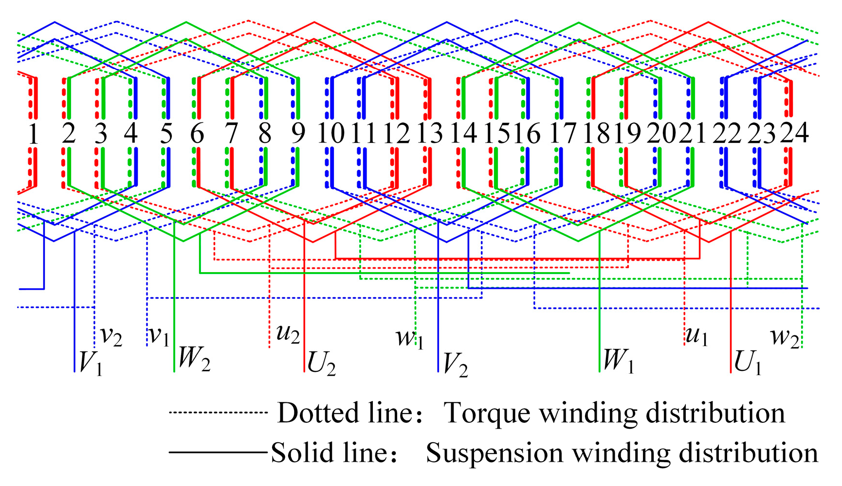
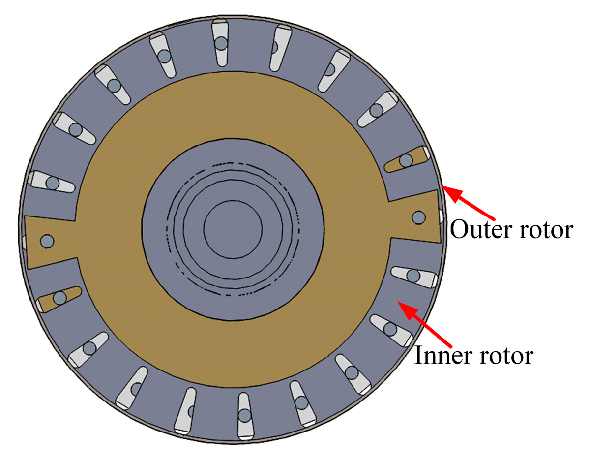
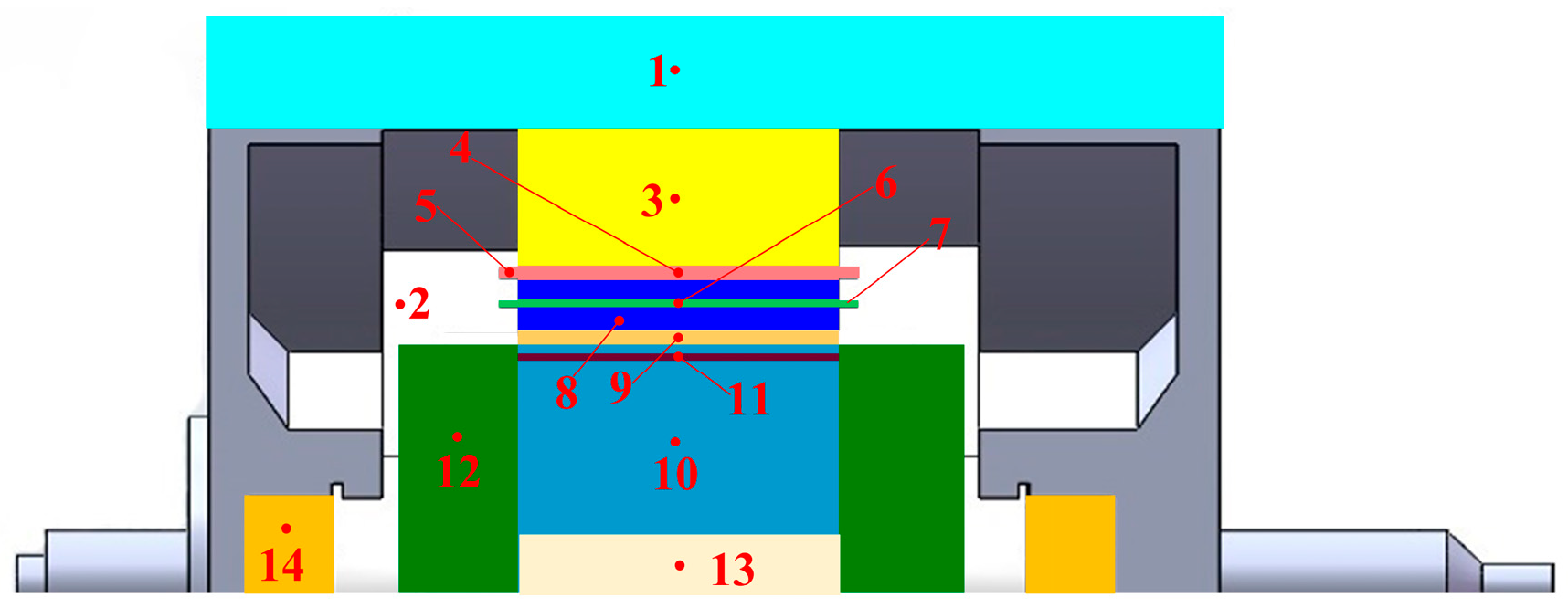
The structure of the CCR-BIM is shown in Figure 1. The CCR-BIM consists of two parts: stator and rotor. The stator is composed of two parts: the stator core and the stator winding. The stator core is made of laminated silicon steel sheets in the same way as the traditional induction motor manufacturing process. There are 24 slots on the stator core. The stator winding is embedded and wound by the torque winding and the suspension winding. Both the torque winding and the suspension winding adopt a three-phase single-layer distributed connection mode. As illustrated in Figure 2, the distribution of torque winding and suspension winding is given. The torque winding is wound as one pair of poles, and the suspension winding is wound as two pairs of poles. The torque winding is placed at the bottom of the stator slot, and the suspension winding is placed at the top of the stator slot. For the composite rotor part, the outer rotor is a solid layer. The inner rotor is an improved special pole rotor structure [17]. There are 20 slots on the inner rotor core. The inner rotor is inside the outer rotor. The outer rotor and the inner rotor are closely attached through the insulating layer. Figure 3 is a sectional view of the composite rotor.
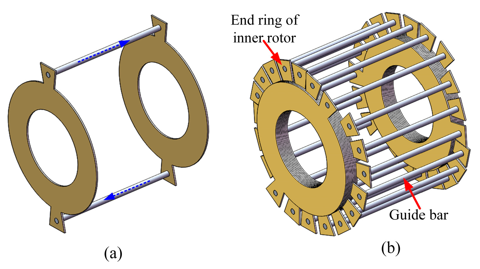
Compared with the traditional squirrel cage rotor, Single rotor guide rod set is an annular structure composed of two independent guide bars connected head and tail through two end rings, as shown in Figure 4a. Ten independent annular structures are combined into a cage rotor structure, as shown in Figure 4b. As analyzed in reference [18], the rotor with this structure only induces the torque winding (P1 = 1) and shields the suspension winding (P2 = 2), which can prevent the interference of the suspension winding to the torque. This cage structure is called a special pole structure.
According to the suspension mechanism of the bearingless motor, under the conditions that the difference between the pole pairs of torque winding and suspension winding is ±1, the angular frequency of torque winding and suspension winding is equal. The rotation directions of the two windings are consistent, the stable suspension force controllable in any direction can be generated by adjusting the initial phase angle difference in the two windings [19,20]. The difference between the pole pairs of the torque winding and the suspension winding of the proposed motor is −1. By setting the angular frequency and rotation direction of the two windings, the controllable radial suspension force can be realized, and the rotor can realize stable suspension.
This article takes the rated power 2 kW CCR-BIM as the research object. The main parameters of the motor are shown in Table 1.

3. LPTN Model of CCR-BIM

The motor is a complex thermal field system. When calculating the motor temperature using the LPTN model, some necessary simplifications need to be made according to the actual situation. Based on this, the following assumptions are put forward: (1) The inner cavity structure of CCR-BIM is symmetrical. (2) The temperature field distribution of CCR-BIM is symmetrical along the circumferential direction of the motor, and the cooling conditions in the circumferential direction are the same. (3) The external temperature conditions of CCR-BIM are the same at any point. (4) The skin effect of torque winding and suspension winding is ignored. (5) The effect of radiation heat dissipation on the temperature field distribution is ignored. (6) Due to the particularity of CCR-BIM, air cooling and other heat dissipation methods are ignored.

3.1. Modeling

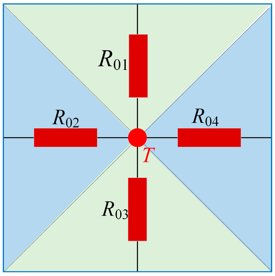
Based on the motor topology analysis and considering the above assumptions, the motor topology was divided into an infinite number of orthogonal thermal network nodes. The centers of these network elements were defined as the nodes of the thermal network, and the scattered parameters were converted into centralized parameters. Thermal network node connections make up the thermal network model. In this article, the meshing method was used to establish the thermal network nodes. Figure 5 shows the cross-shaped mesh used in the LPTN model [21,22,23].
In the cross-shaped grid, the center of the grid temperature field was set to the temperature node T, and its heat was dissipated to the surroundings. The basic grid element contains four thermal resistances in the tangential and radial directions, respectively, and the equivalent area was replaced by thermal resistances R01, R02, R03 and R04. If it is adiabatic in one direction, that is, there is no heat transfer, the thermal resistance is considered infinite. If there is complete heat transfer in one direction, the thermal resistance is considered to be zero. The more orthogonal thermal network nodes, the more accurate the calculated temperature nodes, but the greater the amount of calculation.
The proposed motor temperature network node selection is shown in Figure 6. Node 1 is the motor casing temperature; the iron loss of the stator yoke is distributed at node 2; the iron loss of the stator teeth is distributed at node 8; the copper loss of the torque winding is distributed at nodes 4 and 5, where 4 represents the copper loss in the torque winding slot, and 5 represents the copper loss at the end of the torque winding; the copper loss of the suspension winding is distributed at nodes 6 and 7, where 6 represents the copper loss in the suspension winding slot, and 7 represents the copper loss at the suspension winding end; the composite rotor loss is distributed at nodes 9, 10, 11, 12, 13, 14, among which the eddy current loss of the outer rotor is distributed at node 9, the aluminum loss is distributed at node 11 of the aluminum bar, the loss of rotor core is distributed at node 10 of the inner rotor core, and the end ring loss of inner rotor is distributed at node 12; the temperature of the center of the rotating shaft is Node 13; and the temperature of the shaft end is node 14.
Based on the axial symmetry of the CCR-BIM, 1/4 of the proposed motor was selected as the modeling area of the LPTN model. The selected area of the CCR-BIM was divided into multiple orthogonal thermal network nodes by the orthogonal grid, and the network nodes were connected by thermal resistance. The LPTN model of the CCR-BIM is shown in Figure 7. Among them, T1 represents the motor casing temperature node; T2 represents the ambient temperature node in the motor; T3 represents the stator yoke temperature node; T4 and T5 represent the torque winding temperature node, where T4 represents the torque winding temperature node in the stator core slot, and T5 represents the temperature node at the end of the torque winding; T6 and T7 represent the temperature node of the motor suspension winding, where T6 represents the temperature node of the suspension winding in the stator core slot and T7 represents the temperature node of the end of the suspension winding; T8 represents the temperature node of the stator tooth; T9T14 represents the motor composite rotor temperature nodes, where T9 represents the outer rotor temperature node, T10 represents the rotor core temperature node, T11 represents the inner rotor bar temperature node, T12 represents the end ring temperature node of the inner rotor; and T13T14 represents the shaft temperature node, where T13 represents the center point temperature of the shaft, and T14 represents the temperature of the shaft end in the motor cavity.
T1, T2, T13, and T14 are zero heat source nodes, and T3T12 are heat source nodes. Considering that the CCR-BIM has no friction with the auxiliary bearing during operation, the bearing temperature node is ignored.

3.2. Thermal Resistance

The essential expression for the definition of thermal resistance is R = ΔT/P, ∆T is the temperature difference between two temperature nodes, and P is the heat flow between the two temperature nodes. Thermal resistance Ri,j represents the thermal resistance between temperature nodes Ti, Tj, where |Ri,j| = |Rj,i|. The modes of heat transfer between temperature nodes include thermal conduction, convection thermal dissipation, and thermal radiation. But due to the small power and low temperature of the motor proposed in this article, the thermal radiation was ignored. The thermal resistance is only conduction thermal resistance and the convective heat dissipation thermal resistance. In Figure 7, R1R14 represent the conduction thermal resistance between the heat sources, and R15R23 represent the convective heat dissipation thermal resistance between the heat sources.
The equation for calculating the conduction thermal resistance is as follows:
R d = d S d λ
where Rd is the conduction thermal resistance, d is the distance between temperature nodes, Sd is the thermal conduction contact surface area, and λ is the thermal conductivity of the material. It can be seen from Equation (1) that the conduction thermal resistance is related to the thermal conductivity of the material and the structural size of the analyzed motor.
The equation for calculating the convective heat dissipation thermal resistance is as follows:
R v = 1 S v α v
where Rv is the convective heat dissipation thermal resistance, Sv is the heat dissipation contact surface area, and αv is the heat dissipation coefficient. It can be seen from Equation (2) that the convective heat dissipation thermal resistance is related to the area of the convective heat dissipation surface and the convective heat dissipation coefficient. And the convective heat dissipation coefficient is related to the physical properties of the fluid, the flow state, and the surface condition of the convective heat dissipation surface.
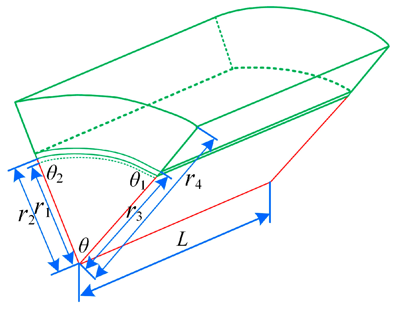
According to the setting of the orthogonal thermal network nodes, and considering the cylindrical shape of the motor and the symmetry of its operation, any small θ angle on the motor circumference is taken as the selected area to calculate the conduction thermal resistance and convective heat dissipation thermal resistance. The selected area is shown in Figure 8. Where r1 is the radius of the inn er rotor, r2 is the radius of the outer rotor, r3 is the radius of the stator, r4 is the radius of the stator, and L is the effective length of the thermal model.
The conduction thermal resistance R10 in the thermal network model was analyzed as an example. The heat dissipation area between nodes T9 and T10 is as follows:
S 9 , 10 = θ r a L
where ra = (r1 + r2)/2.
The conduction thermal resistance R10 is as follows:
R 10 = d 0 S 9 , 10 λ 0
where d0 is the distance between the temperature nodes of the outer rotor and the inner rotor, and λ0 is the thermal conductivity between the temperature nodes of the outer rotor and the inner rotor. By consulting the data, the thermal conductivity of silicon steel material can be obtained, and, then, the value of thermal conductivity R10 can be obtained.
A similar process can obtain the values of R1, R2, R6R8 and R13.
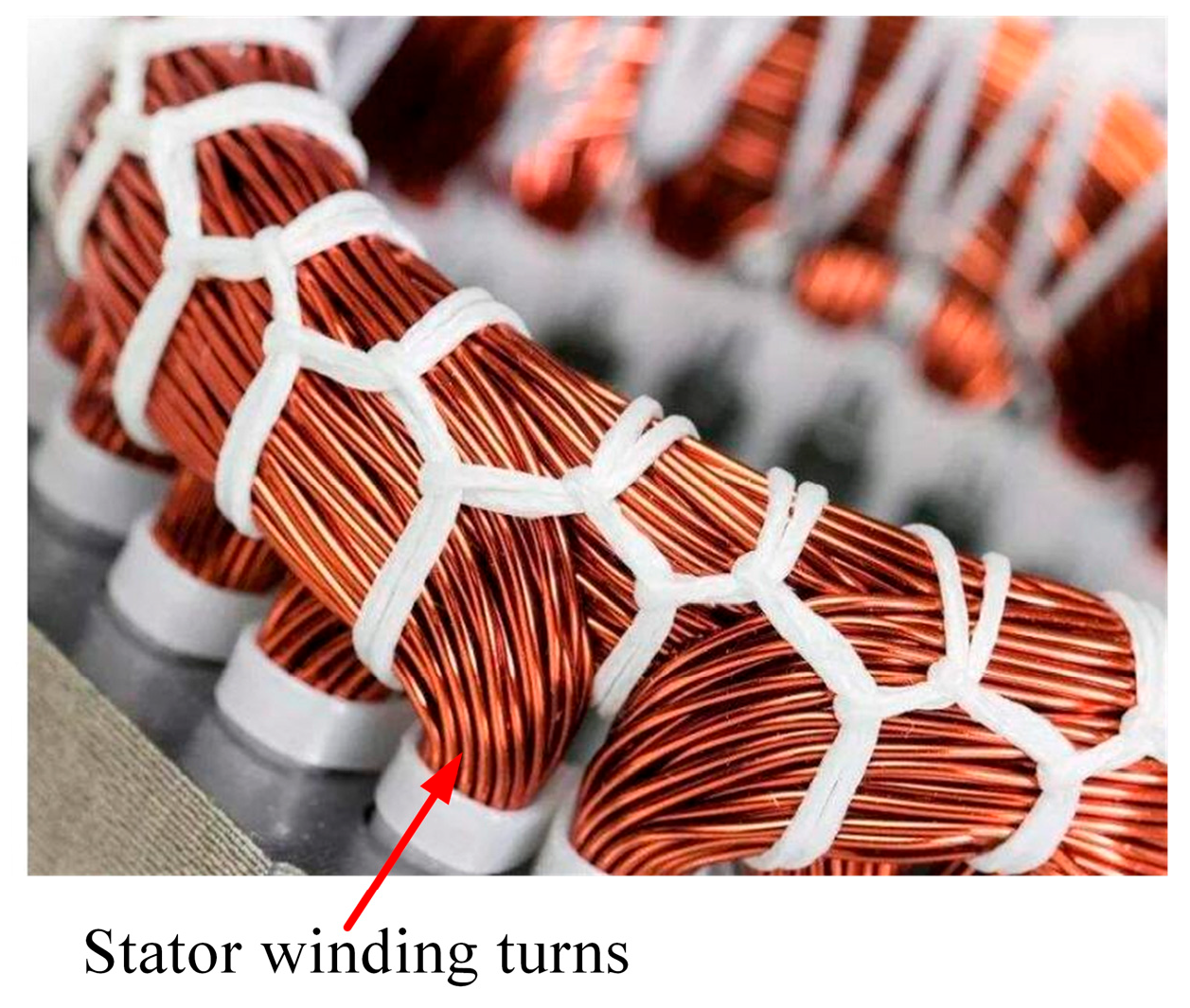
The conduction thermal resistance R4 in the thermal network model was analyzed as an example. The cross-sectional area of the torque winding between nodes T4 and T5 is composed of stator winding turns, as shown in Figure 9.
The cross-sectional area of the harness is as follows:
S 4 , 5 = A π r b 2
where A is the number of a single conductor, and rb is the radius of a single conductor.
The conduction thermal resistance R4 is as follows:
R 4 = d 1 S 4 , 5 λ 1
where d1 is the distance between the torque winding temperature node in the stator core slot and the temperature node at the end of the torque winding. λ0 is the thermal conductivity between the torque winding temperature node in the stator core slot and the temperature node at the end of the torque winding. By consulting the data, the thermal conductivity of the copper conductor can be obtained, and, then, the value of thermal conductivity R4 can be obtained.
A similar process can obtain the values of R3, R5, R11R14.
The convective heat dissipation thermal resistance R23 in the thermal network model was analyzed as an example. The heat exchange in the air gap between stator and rotor was carried out in the centrifugal force field, and there is secondary flow. The outer cylinder of the stator was fixed, while the inner cylinder of the rotor was rotating. The air gap heat dissipation coefficient between T8 and T9 is expressed as follows [23]:
α a i r = N u λ g
where Nu is the dimensionless Nusselt coefficient. g is the air gap length, and g = θrc. When Ta < 41.2, the fluid in the air gap is in a laminar flow state, Nu = 2; when Ta > 41.2, the fluid in the air gap is in a turbulent flow state, Nu = 0.42 T 0.5 a P 0.25 r , Ta is the Teilor number, and Pr is the dimensionless Prandtl coefficient.
The Teilor number Ta is defined as
T a = r c 0.5 g 1.5 ω v
where rc = (r2+ r3)/2, ω is the rotor angular velocity, and v is the air viscosity.
The heat conduction area between temperature nodes 8 and 9 is as follows:
S 8 , 9 = θ r c L
The heat dissipation resistance R23 is as follows:
R 23 = 1 S 8 , 9 α a i r
A similar process can obtain the values of R15R22.
The thermal resistance calculations are based on the material properties listed in Table 2, which includes thermal conductivity λ, specific heat capacity, and density of key components.

3.3. Heat Sources

In the process of rotor suspension and electromechanical energy conversion of the CCR-BIM, the motor loss will be generated and become the heat source in the equivalent thermal network model of the motor lumped parameters. The losses in the CCR-BIM mainly include the copper loss of the torque winding PCu1, the copper loss of the suspension winding PCu2, the copper loss of the end ring PCu3, the iron loss of the stator core PFe1, the iron loss of the stator teeth PFe2, the eddy current loss of the outer rotor PEc, and aluminum loss of rotor bars PAL.
(1)
Copper loss of the two windings
Winding copper loss is determined by winding current and winding coil resistance. When the winding is powered by three-phase AC, the coil will produce additional loss, and the loss value increases with the increase in current frequency. However, due to the low current frequency, the additional loss is ignored. The calculation formula of winding copper loss is as follows [24]:
P C u = 3 I C u 2 R C u
where ICu is the winding current, and RCu is winding copper resistance.
(2)
Copper loss of the end ring
The end ring loss P C u 3 = I r o 2 R r o consists of the end ring loss of the inner rotor and the outer rotor. The end ring loss is caused by the current flowing through the end ring resistance. The calculation formula is the following:
P C u 3 = I r o 2 R r o
where Iro is the end ring current, and Rro is the end ring resistance.
(3)
Iron loss of the stator core
Stator core loss is affected by magnetic density amplitude, magnetic field frequency, core lamination coefficient and manufacturing process. Under the excitation of a sinusoidal alternating magnetic field, the loss in unit weight core is expressed as follows [25]:
P F e = K s e f 2 B s max 2 + K s h f B s max 2
where f is the frequency; Ks–e and Ks–h are eddy current loss coefficient and hysteresis loss coefficient, respectively; and Bs–max is the maximum magnetic flux density of stator core when excited by AC power supply. Items 1 and 2 on the right of Equation (13) are eddy current loss and hysteresis loss of stator core, respectively.
(4)
Iron loss of the stator teeth
The iron loss of the stator teeth adopts the volume calculation method, and the unit iron loss of the stator teeth is determined according to the material, lamination coefficient and manufacturing process. Then, the iron loss of the stator teeth is determined by calculating the volume of the stator teeth [26].
P T = 2.5 p V T
where p is the unit iron loss of the stator teeth, and VT is the volume of the stator teeth.
(5)
Eddy current loss of the outer rotor
In the solid layer of the outer rotor, only eddy current loss is considered, and magnetic field loss is no longer considered.
P E c = K r e f 2 B r max 2
where Kr–e is the eddy current loss coefficient of the solid layer, and Bs–max is the maximum magnetic flux density of the solid layer when excited by the AC power supply.
(6)
Aluminum loss of rotor bar
The aluminum loss of the guide bar is calculated according to Joule’s law:
P A L = I A L 2 R A L
where IAL is the induced current in the guide bar, and RAL is the resistance of the guide bar.

3.4. Thermal Network Matrix

The thermal network matrix formula is as follows:
G T = W
where G is the thermal conductivity matrix, G = 1/R, and R is the thermal resistance matrix; T is the temperature node array; and W is the node heat source array [27].
There are 14 thermal nodes in the thermal network model of the CCR-BIM, i.e., n = 14. According to the nodal method of Kirchhoff’s law, the heat balance equations of each node are established, and, finally, the heat balance equations of the CCR-BIM are obtained:
G 1 , 1 G 1 , 2 G 1 , j G 1 , N 1 G 1 , N G 2 , 1 G 2 , 2 G 2 , j G 2 , N 1 G 2 , N G j , 1 G j , 2 G j , j G j , N 1 G j , N G N 1 , 1 G N 1 , 2 G N 1 , j G N - 1 , N 1 G N 1 , N G N , 1 G N , 2 G N , j G N , N 1 G N , N T 1 T 2 T j T N - 1 T N = W 1 W 2 W j W N - 1 W N
where GN,N is the self-derivation of the Nth unit, and G(i,j) (ij) is the mutual conductance between the ith node and the jth node, G(i,j) = G(j,i). The Gauss–Seidel iteration method was used to solve these equations in Matlab 2016b. The temperature node values of the CCR-BIM calculated by the equivalent thermal network method are obtained. The calculated values of LPTN nodes are shown in Table 3.

4. FETM Analysis of Motor Temperature Field

4.1. Finite Element Modeling

To verify the correctness of the LPTN model of the CCR-BIM and further study the motor temperature distribution, the FETM method is introduced in this article. In the Cartesian coordinate system, the solution of the temperature field of the CCR-BIM finite element calculation element can be attributed to the boundary value problem of Formula (19) [28].
( K x T x ) x + ( K y T y ) y + ( K z T z ) z = q T ( x , y , z ) | S 1 = T 1 h S 2 ( T T 0 ) | S 2 = K T n
where T is the temperature; Kx, Ky and Kz are the thermal conductivity along the x, y and z directions, respectively; T1 is the given temperature on the boundary surface S1; n is the normal vector on the boundary surface (S1, S2); hS2 is the heat dissipation coefficient of the surface S2; T0 is the temperature of the medium around S2; and q is the heat flux density of the heating source.
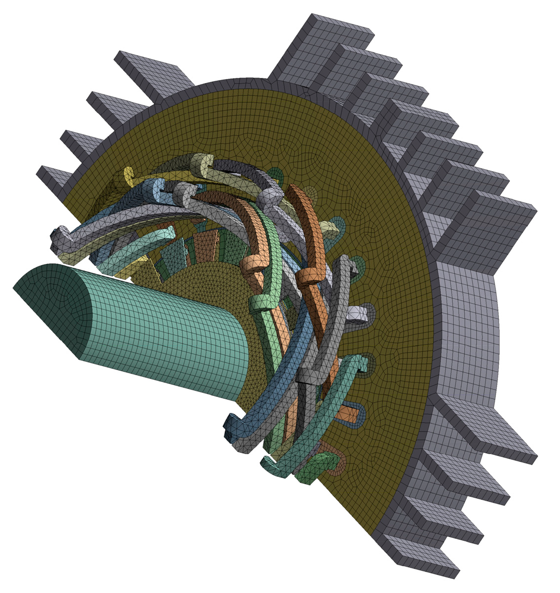
The temperature field modeling and simulation of the CCR-BIM are carried out under the rated operating conditions. First, considering the equivalent insulation and air gap, a finite element structural model of the CCR-BIM is established based on the motor structure. Second, the finite element structural model of the CCR-BIM is coupled to the steady-state temperature field of ANSYS Workbench 8.0. The meshing of the thermal model is shown in Figure 10. The finer the mesh division, the closer the obtained temperature value is to the actual value, but the finer the division, the greater the amount of calculation and the longer the calculation time. The heat source and heat transfer medium, torque windings, suspension windings, bars, and other vital areas have smaller mesh, while non-key areas have slightly larger meshes. Third, the parameters including the conductivity of each material are set, and the heat source and convection coefficient are set. Finally, the thermal model is solved to obtain the temperature field distribution of each component of the CCR-BIM. Temperature nodes such as stator core, torque winding, suspension winding, outer rotor, inner rotor, inner rotor aluminum strip and motor shaft were observed.
The key simulation parameters, including mesh configuration, boundary conditions and solver settings, are systematically summarized in Table 4 to enhance methodological transparency.

4.2. Simulation Results and Analysis of FETM

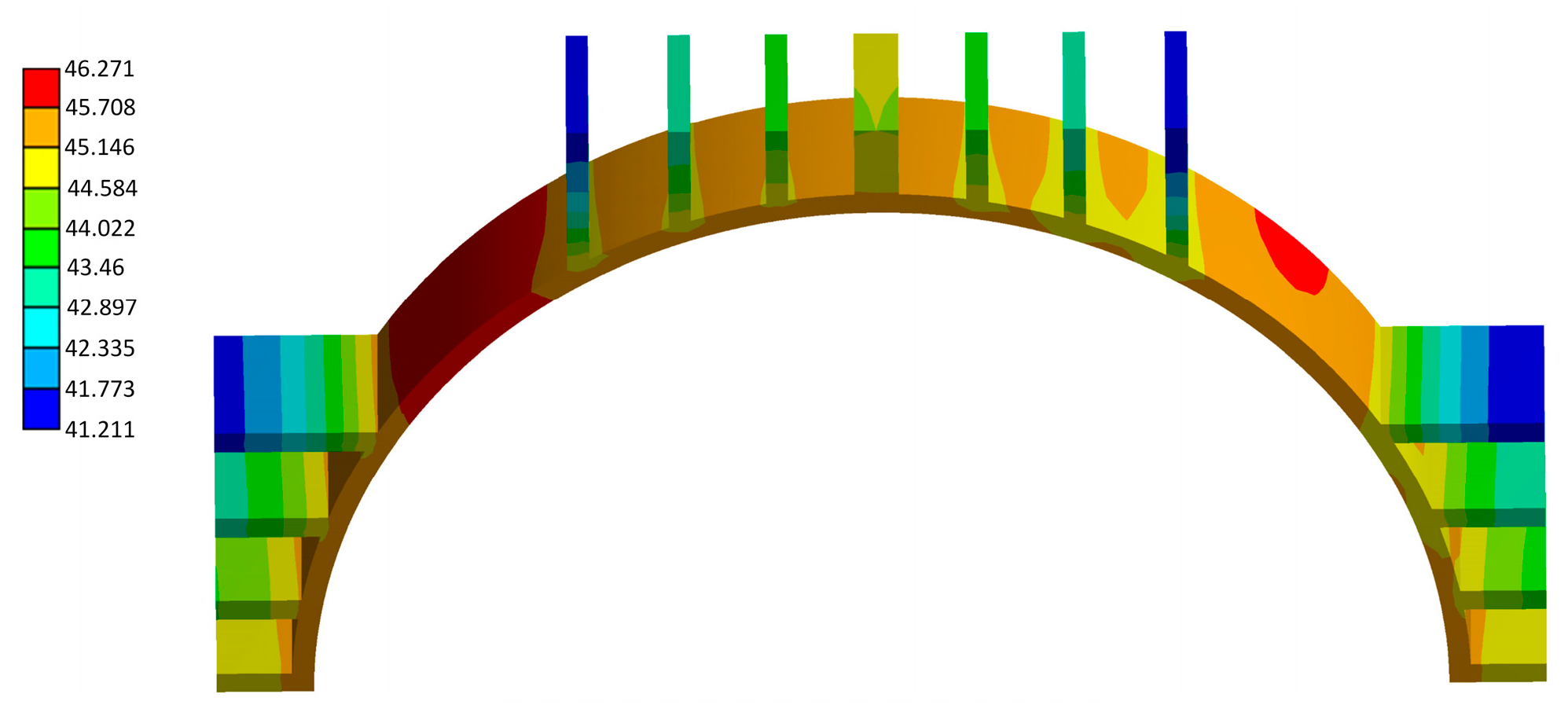
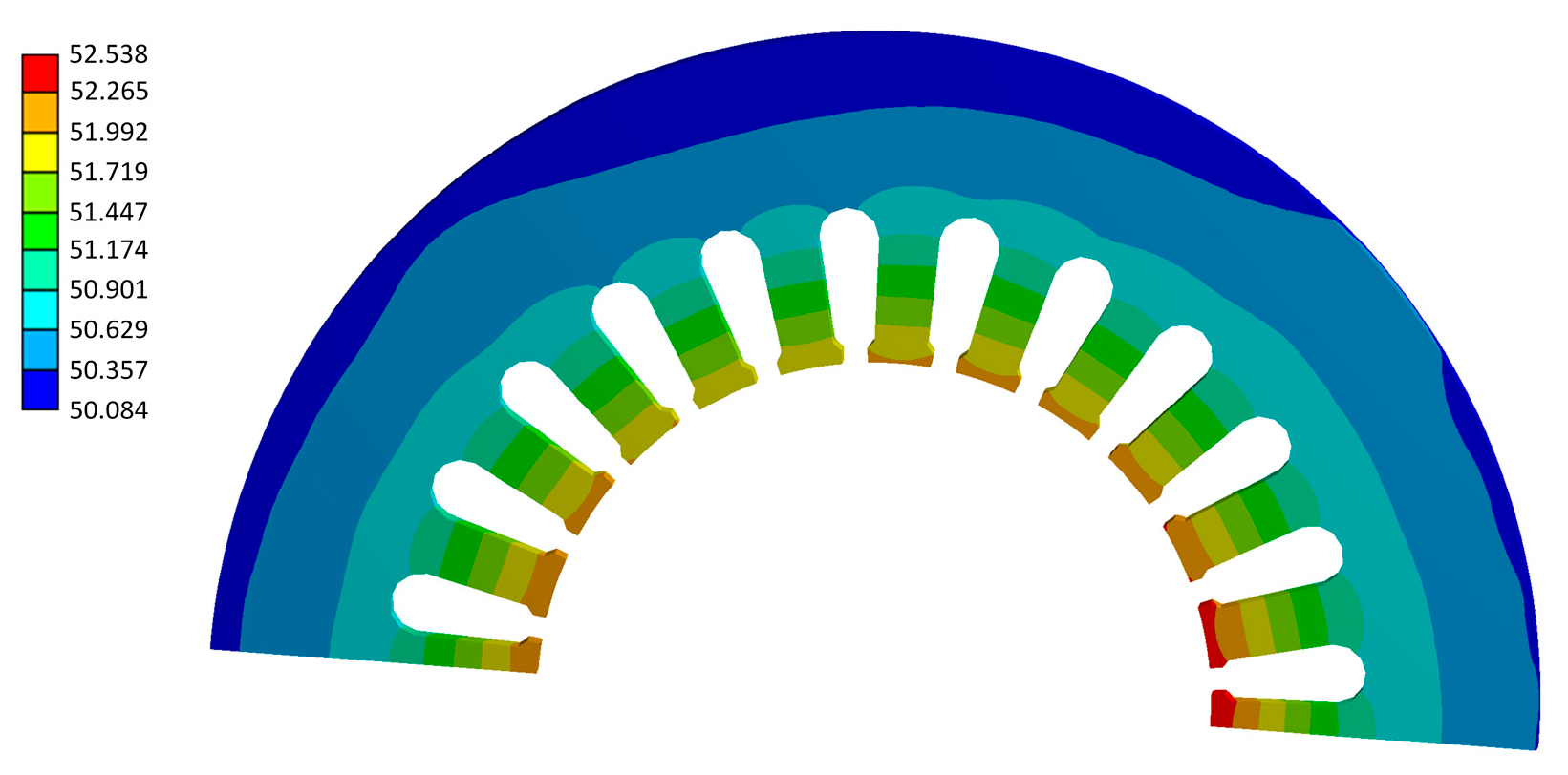
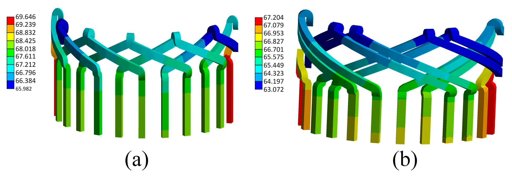
According to the FETM, the temperature distribution of the CCR-BIM under rated conditions is obtained. As shown in Figure 11, Figure 12, Figure 13 and Figure 14, thermal analysis on critical components of the motor is carried out.
Figure 11 shows the temperature distribution of the motor casing, which is mainly derived from the heat conduction of the stator core. Due to the unbalanced magnetic field, the temperature distribution at each point is slightly different.
Figure 12 shows the temperature distribution of the stator core. There are two windings in the middle part of the stator core to generate heat. The heat dissipation is slow, and the temperature is high. The temperature of the head and tail ends of the stator core is lower than the temperature of the middle part. Because the head and tail ends are in contact with the air inside the motor, the heat dissipation area is large, which can effectively dissipate heat. The temperature of the stator teeth is higher than that of the stator yoke because the iron loss of the stator teeth is higher than that of the stator yoke, and the teeth are close to the stator winding and the rotor heat source.
Figure 13 shows the temperature distribution of torque winding and suspension winding. The wiring distribution of the two windings is similar, and the two windings are stacked to transfer heat to each other. However, the torque winding current is larger than the suspension winding current. Under the same heat dissipation environment, the torque winding temperature is higher than the suspension winding temperature. The middle part of the windings is in a closed environment, resulting in poor heat dissipation and high temperature. The head and tail ends of the two windings have a large contact surface with the air, and the temperature is lower than that of the winding part.
Figure 14 shows the temperature distribution of the composite rotor. During the rotor rotation, the frequency of the inner rotor core is low, and the iron loss is small. The primary source of the temperature rise is the Joule heat of the aluminum bar. The temperature distribution of the rotor core and the rotor bar is shown in Figure 14a,b. In the start-up stage, the major loss of the outer rotor is eddy current loss. In the stable operation stage, the rotor frequency is low, and the solid layer loss is small. The solid layer is in close contact with the inner rotor core, and the temperature distribution of the two is similar. The temperature distribution of the outer rotor is shown in Figure 14c. The rotating shaft is embedded in the rotor iron core, and heat exchange is carried out through the rotor iron core. By setting the length of the rotating shaft, the part longer than the rotor iron core is in contact with the air temperature inside the motor. The temperature is low. The heat dissipation of the part in contact with the rotor iron core is poor. The temperature is high. The temperature distribution of the rotating shaft is shown in Figure 14d.
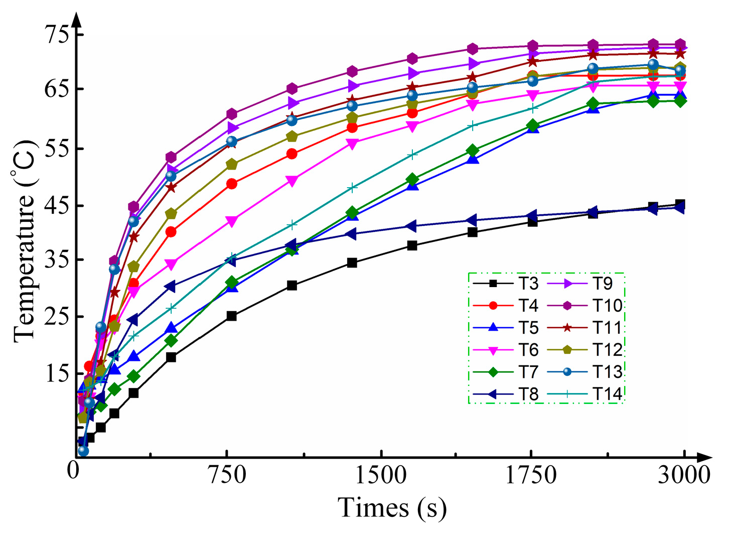
The temperature rise process of each component can be obtained in the FETM. The motor temperature rise curve of key component is shown in Figure 15. It takes about 30 min for each motor component to reach a stable temperature.
The temperature node values of the CCR-BIM obtained by the FETM are shown in Table 5.

5. Temperature Test Platform of CCR-BIM

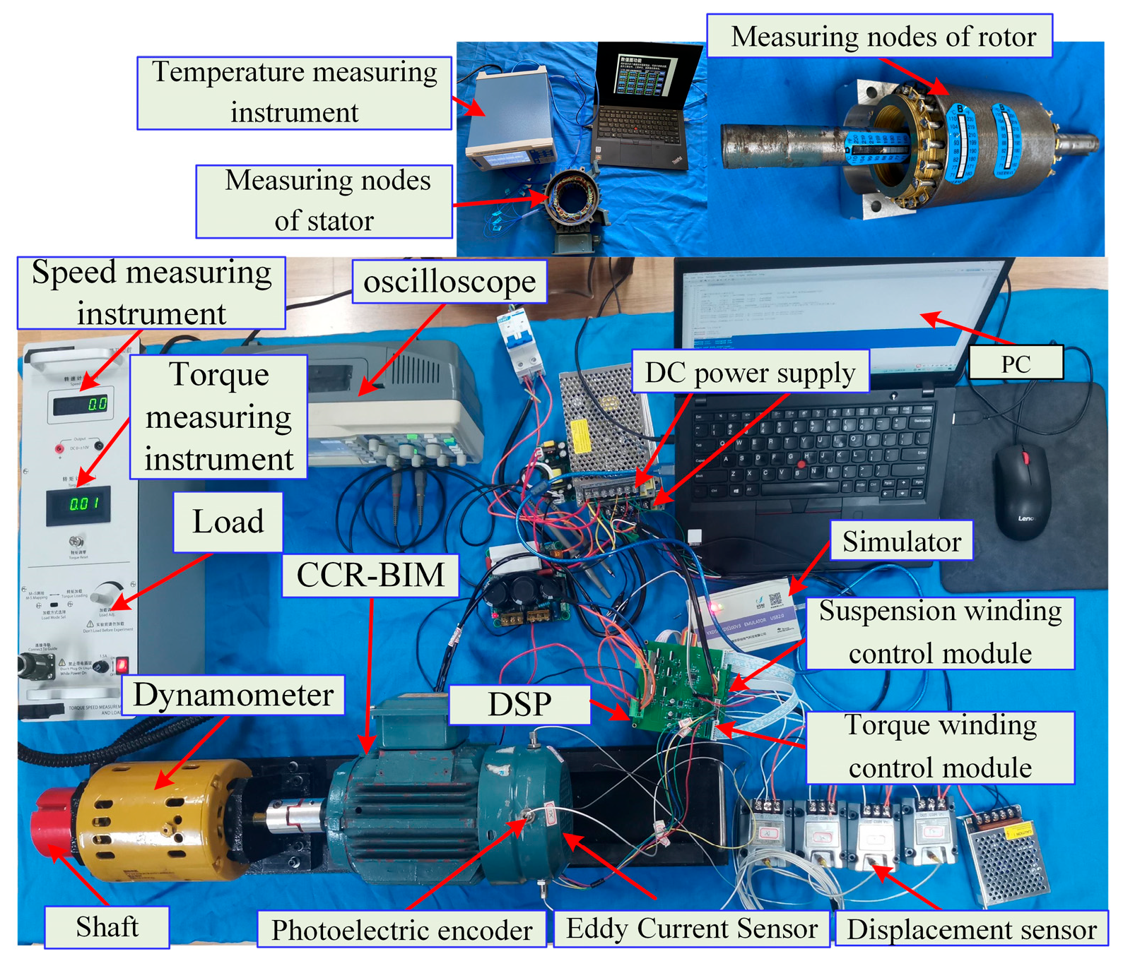
To further verify the effectiveness of the LPTN model and FETM, the temperature test platform of CCR-BIM is built, and the temperature test of the motor is carried out. The temperature test experimental platform of the CCR-BIM is composed of the motor, controller, driving circuit, multi-channel temperature measuring instrument, K-type temperature probe, Thermax temperature paper, etc. The experimental platform is shown in Figure 16.
The motor casing, the ambient temperature node in the motor, the stator core yoke, the end of the stator core, the stator winding center, and the stator winding end are measured by the embedded K-type temperature probe. Stator teeth, outer rotor, end ring and rotating shaft end are measured by Thermax temperature paper. Thermax temperature paper is used, combined with rapid motor disassembly, to measure and read the temperature. T10, T11 and T13 could not be obtained due to measurement constraints. The steady-state temperature node values of the motor under rated operating conditions are shown in Table 6.
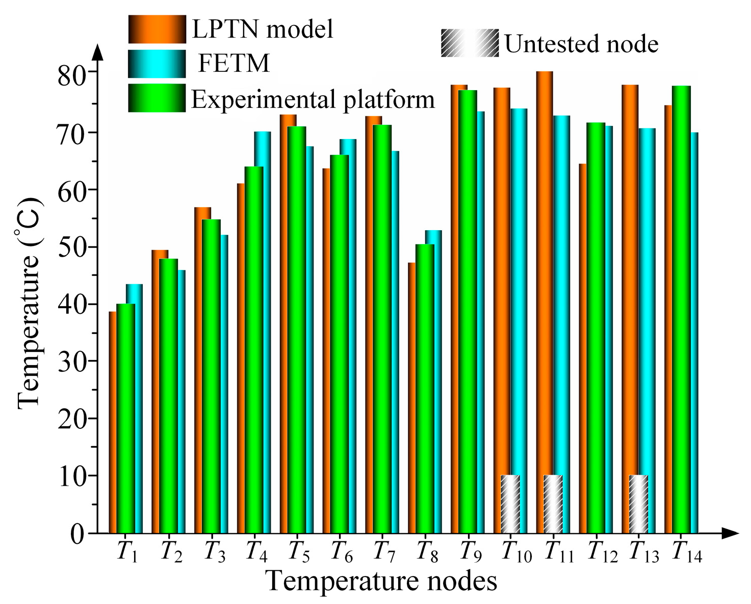
As shown in Figure 17, the results were obtained by the LPTN method, and comparisons were made between the results of the LPTN method, FETM, and temperature testing platform. There are resultant errors due to the precise calculation error of thermal resistance, the position error between the calculation nodes and the measurement nodes, and the deviation between the ideal condition and the experimental condition. However, there is a small error between the calculated data and the experimental data. The maximum error of the three is 13.5%, and the minimum error is 4.3%, indicating that the calculated results are in good agreement with the experimental results.

6. Conclusions

This study successfully integrates lumped parameter thermal network (LPTN) and finite element thermal model (FETM) methods to analyze the thermal performance of composite cage rotor bearingless induction motors (CCR-BIM). The LPTN model, developed through a meshing-based discretization approach, provides a computationally efficient means of predicting steady-state temperatures. The FETM further validates the LPTN results by simulating detailed temperature distributions and transient behaviors.
Experimental validation using a 2 kW CCR-BIM test platform demonstrates the accuracy and reliability of both models, with temperature predictions closely aligning with measured data. The maximum error between the predicted and experimental temperatures is 13.5%, highlighting the reliability of the proposed dual-model approach.
The dual-model framework provides a comprehensive and efficient solution for thermal analysis, enabling rapid and accurate temperature prediction. This approach not only facilitates the design and optimization of CCR-BIM but also enhances their performance and reliability in high-speed and high-precision applications.

Author Contributions

Methodology, C.D.; Software, J.F.; Validation, C.L., J.Z. and J.C.; Formal analysis, C.L., J.Z. and J.C.; Investigation, C.D. and C.L.; Resources, J.F.; Data curation, C.L.; Writing—original draft, C.D. and C.L.; Writing—review & editing, C.L., J.Z. and J.C.; Visualization, C.D.; Project administration, C.D.; Funding acquisition, J.F. All authors have read and agreed to the published version of the manuscript.

Funding

This work was supported by the Doctoral Research and Innovation Project of Jiangsu Province (KYCX213362), and Start-up Fund for Distinguished Scholars of West Anhui University by Chengling Lu.

Data Availability Statement

The original contributions presented in the study are included in the article, further inquiries can be directed to the corresponding author/s.

Conflicts of Interest

The author declares no conflicts of interest.

References

  1. Tera, T.; Yamauchi, Y.; Chiba, A.; Fukao, T.; Rahman, M. Performances of bearingless and sensorless induction motor drive based on mutual inductances and rotor displacements estimation. IEEE Trans. Ind. Electron. 2006, 53, 187–194. [Google Scholar] [CrossRef]
  2. De Freitas Nunes, E.A.; Salazar, A.O.; Villarreal, E.R.L.; Souza, F.E.C.; Dos Santos, L.P.; Lopes, J.S.B.; Luque, J.C.C. Proposal of a Fuzzy Controller for Radial Position in a Bearingless Induction Motor. IEEE Access 2019, 7, 114808–114816. [Google Scholar] [CrossRef]
  3. Chen, J.; Fujii, Y.; Johnson, M.W.; Farhan, A.; Severson, E.L. Optimal Design of the Bearingless Induction Motor. IEEE Trans. Ind. Appl. 2020, 57, 1375–1388. [Google Scholar] [CrossRef]
  4. Victor, V.F.; Quintaes, F.O.; Lopes, J.S.B.; Junior, L.d.S.; Lock, A.S.; Salazar, A.O. Analysis and Study of a Bearingless AC Motor Type Divided Winding, Based on a Conventional Squirrel Cage Induction Motor. IEEE Trans. Magn. 2012, 48, 3571–3574. [Google Scholar] [CrossRef]
  5. Lu, C.; Yang, Z.; Sun, X.; Ding, Q.; Zhao, Q. A decoupling control of composite cage rotor bearingless induction motor based on SA-PSO support vector machine inverse. Int. Trans. Electr. Energy Syst. 2021, 31, e12988. [Google Scholar] [CrossRef]
  6. Kauh, S.; Hahn, S.-Y.; Lee, Y. Thermal analysis of induction motor with forced cooling channels. IEEE Trans. Magn. 2000, 36, 1398–1402. [Google Scholar] [CrossRef]
  7. Kokate, R.; Seele, J.; Park, C.; Mitsingas, C.; Schroen, E.; Kweon, C.-B. Thermal Modeling and Analysis of an Axial Flux Permanent Magnet Motor. In Proceedings of the AIAA AVIATION FORUM AND ASCEND 2024, Las Vegas, NV, USA, 29 July–2 August 2024. [Google Scholar]
  8. Ebrahimi, Y.; Feyzi, M.R. Lumped Parameter Thermal Model for Axial Flux Switched Reluctance Motors. Electr. Power Components Syst. 2017, 45, 2318–2326. [Google Scholar] [CrossRef]
  9. Arbab, N.; Wang, W.; Lin, C.; Hearron, J.; Fahimi, B. Thermal Modeling and Analysis of a Double-Stator Switched Reluctance Motor. IEEE Trans. Energy Convers. 2015, 30, 1209–1217. [Google Scholar] [CrossRef]
  10. Guo, B.; Huang, Y.; Guo, Y.; Zhu, J. Thermal Analysis of the Conical Rotor Motor Using LPTN with Accurate Heat Transfer Coefficients. IEEE Trans. Appl. Supercond. 2016, 26, 0611507. [Google Scholar] [CrossRef]
  11. Vahedi, P.; Ganji, B.; Afjei, E. Lumped thermal model for the multi-layer switched reluctance motor. IET Electr. Power Appl. 2020, 14, 1873–1885. [Google Scholar] [CrossRef]
  12. Chen, Q.; Zou, Z.; Cao, B. Lumped-parameter thermal network model and experimental research of interior pmsm for electric vehicle. CES Trans. Electr. Mach. Syst. 2017, 1, 367–374. [Google Scholar] [CrossRef]
  13. Huang, Y.; Zhu, J.; Guo, Y. Thermal Analysis of High-Speed SMC Motor Based on Thermal Network and 3-D FEA with Rotational Core Loss Included. IEEE Trans. Magn. 2009, 45, 4680–4683. [Google Scholar] [CrossRef]
  14. Zhu, Z.; Zhang, W.; Li, Y.; Guo, J. Thermal Analysis of Axial Permanent Magnet Flywheel Machine Based on Equivalent Thermal Network Method. IEEE Access 2021, 9, 33181–33188. [Google Scholar] [CrossRef]
  15. Staton, D.; Popescu, M. Analytical thermal models for small induction motors. COMPEL—Int. J. Comput. Math. Electr. Electron. Eng. 2010, 29, 1345–1360. [Google Scholar] [CrossRef]
  16. Yu, W.; Hua, W.; Qi, J.; Zhang, H.; Zhang, G.; Xiao, H.; Xu, S.; Ma, G. Coupled Magnetic Field-Thermal Network Analysis of Modular-Spoke-Type Permanent-Magnet Machine for Electric Motorcycle. IEEE Trans. Energy Convers. 2020, 36, 120–130. [Google Scholar] [CrossRef]
  17. Ye, X.; Yang, Z.; Zhang, T. Modelling and performance analysis on a bearingless fixed-pole rotor induction motor. IET Electr. Power Appl. 2019, 13, 251–258. [Google Scholar] [CrossRef]
  18. Yang, Z.; Ding, Q.; Sun, X.; Lu, C. Design and Analysis of a Three-Speed Wound Bearingless Induction Motor. IEEE Trans. Ind. Electron. 2021, 69, 12529–12539. [Google Scholar] [CrossRef]
  19. Bu, W.; Huang, Y.; Li, Z.; Shi, H.; Shi, J. Diaplacement sensorless control strategy of bearingless induction motor. Int. J. Appl. Electromagn. Mech. 2017, 54, 597–610. [Google Scholar] [CrossRef]
  20. Yang, Z.; Sun, C.; Sun, X.; Sun, Y. An Improved Dynamic Model for Bearingless Induction Motor Considering Rotor Eccentricity and Load Change. IEEE Trans. Ind. Electron. 2022, 69, 3439–3448. [Google Scholar] [CrossRef]
  21. Chen, W.; Wu, G.; Li, Y.; Ma, J. Coupled magnetic-thermal fields analysis using an adaptive single-mesh method. Int. J. Appl. Electromagn. Mech. 2019, 62, 45–57. [Google Scholar] [CrossRef]
  22. Zhao, W.; Cao, D.; Ji, J.; Huang, L.; Liu, T. A Generalized Mesh-Based Thermal Network Model for SPM Machines Combining Coupled Winding Solution. IEEE Trans. Ind. Electron. 2021, 68, 116–127. [Google Scholar] [CrossRef]
  23. Zhang, F.; Jiang, X.; Li, Y.; Zhang, Y.; Wang, J. Thermal Calculation on Brushless Doubly-fed Machines with a Magnetic Barrier Rotor. Proc. Chin. Soc. Electr. Eng. 2018, 38, 2745–2752. [Google Scholar] [CrossRef]
  24. Ahmed, F.; Ghosh, E.; Kar, N.C. Transient thermal analysis of a copper rotor induction motor using a lumped parameter temperature network model. In Proceedings of the 2016 IEEE Transportation Electrification Conference and Expo (ITEC), Dearborn, MI, USA, 27–29 June 2016; pp. 1–6. [Google Scholar]
  25. Amara, Y.; Wang, J.; Howe, D. Stator iron loss of tubular permanent-magnet machines. IEEE Trans. Ind. Appl. 2005, 41, 989–995. [Google Scholar] [CrossRef]
  26. Chen, M.; Zhuang, W.; Deng, S.; Zhu, C. Thermal analysis of the triple-phase asynchronous motor-reducer coupling system by thermal network method. Proc. Inst. Mech. Eng. Part D J. Automob. Eng. 2020, 234, 2851–2861. [Google Scholar] [CrossRef]
  27. Benedik, B.; Duhovnik, J.; Rihtaršič, J.; Tavčar, J. Thermal model of through flow universal motor by means of lumped parameter network. Teh. Vjesn. 2017, 24, 405–412. [Google Scholar] [CrossRef]
  28. Zhang, Y.; Ruan, J.; Huang, T.; Yang, X.; Zhu, H.; Yang, G. Calculation of Temperature Rise in Air-cooled Induction Motors Through 3-D Coupled Electromagnetic Fluid-Dynamical and Thermal Finite-Element Analysis. IEEE Trans. Magn. 2012, 48, 1047–1050. [Google Scholar] [CrossRef]
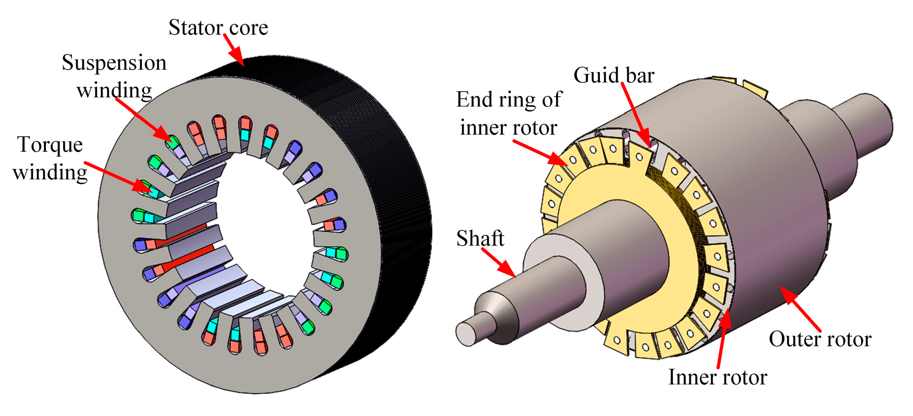
Figure 1. Structure of CCR-BIM.
Energies 18 01816 g001
Figure 2. Distribution of torque winding and suspension winding.
Energies 18 01816 g002
Figure 3. Section of composite rotor.
Energies 18 01816 g003
Figure 4. Cage structure of the inner rotor. (a) Single rotor guide rod set. (b) cage rotor structure.
Energies 18 01816 g004
Figure 5. Cross-shaped grid of LPTN.
Energies 18 01816 g005
Figure 6. Heat source distribution of CCR-BIM.
Energies 18 01816 g006
Figure 7. Thermal network model.
Energies 18 01816 g007
Figure 8. Calculation of unit heat volume.
Energies 18 01816 g008
Figure 9. Turns of two windings.
Energies 18 01816 g009
Figure 10. Meshing of thermal model.
Energies 18 01816 g010
Figure 11. Temperature distribution of motor casing.
Energies 18 01816 g011
Figure 12. Temperature distribution of stator core.
Energies 18 01816 g012
Figure 13. Temperature distribution of two windings. (a) Torque winding. (b) Suspension winding.
Energies 18 01816 g013
Figure 14. Temperature distribution of rotor components: (a) Iron core of inner rotor, (b) Guide bar, (c) Outer rotor, and (d) Rotating shaft.
Energies 18 01816 g014
Figure 15. Temperature rise trend of FETM.
Energies 18 01816 g015
Figure 16. Temperature test platform.
Energies 18 01816 g016
Figure 17. Comparison of results between LPTN model, FETM and experiment.
Energies 18 01816 g017
Table 1. Main parameters of the proposed motor.
ItemValueItemValue
Rated current of torque winding3 ATurns of torque winding60
Rated current of suspension winding0.8 ATurns of suspension winding50
Thickness of outer rotor0.35 mmStator outer diameter/inner diameter125/65 mm
Rated speed3000 rpmOuter diameter of composite rotor64.4 mm
Core length83 mmShaft diameter20 mm
Table 2. Thermal physical parameters of materials.
MaterialThermal Conductivity (W/m·K)Specific Heat (J/kg·K)Density (kg/m³)
Silicon Steel28.54607650
Copper (Winding)4013858960
Aluminum (Bar)2379002700
Shaft Steel434757850
Table 3. Temperature node values from LPTN nodes.
NodeTemperature/°CNodeTemperature/°C
T138.4T846.9
T249.1T977.7
T356.5T1077.2
T460.6T1182.2
T572.6T1264.1
T663.3T1377.7
T772.3T1474.2
Table 4. FEA simulation parameters and boundary conditions.
CategorySpecification
Software PlatformANSYS Workbench 2020 R1
Mesh TypeSOLID187
Mesh SizeCritical Regions (Winding/Rotor): 0.5 mm; Non-critical Regions: 2 mm
Boundary ConditionsAmbient Temperature: 25 °C (Fixed)
Convergence CriteriaRelative Energy Error < 1 × 10⁻⁴
Solver SettingsSteady-State (Newton–Raphson Iterative Method)
Table 5. Temperature node values from FETM.
NodeTemperature/°CNodeTemperature/°C
T143.2T852.5
T245.6T973.1
T352.9T1073.6
T469.6T1172.4
T567.1T1270.6
T668.3T1370.2
T766.3T1468.5
Table 6. Temperature node values from experimental platform.
NodeTemperature/°CNodeTemperature/°C
T139.7T850.1
T247.6T976.8
T354.4T10/
T463.6T11/
T570.5T1271.2
T665.6T13/
T770.8T1477.5
Disclaimer/Publisher’s Note: The statements, opinions and data contained in all publications are solely those of the individual author(s) and contributor(s) and not of MDPI and/or the editor(s). MDPI and/or the editor(s) disclaim responsibility for any injury to people or property resulting from any ideas, methods, instructions or products referred to in the content.