
Research Progress on the Performance Enhancement Technology of Ice-on-Coil Energy Storage


Abstract
1. Introduction
2. Research on Ice-on-Coil Type Ice Melting Methods
2.1. Ice-on-Coil Type Ice Melting Method
2.1.1. Internal Ice Melting Method
2.1.2. External Ice Melting Method
2.1.3. Combined Internal and External Ice Melting Methods
3. Research on Enhanced Heat Transfer of Ice-on-Coil
4. Research on Operation Strategy of the Ice Storage System
5. Discussion and Conclusions
Author Contributions
Funding
Data Availability Statement
Conflicts of Interest
References
- Xie, H.; Jiang, M.; Zhang, D.; Goh, H.H.; Ahmad, T.; Liu, H.; Wu, T. IntelliSense technology in the new power systems. Renew. Sustain. Energy Rev. 2023, 177, 113229. [Google Scholar]
- Li, Z.; Deusen, D. Role of energy storage technologies in enhancing grid stability and reducing fossil fuel dependency. Int. J. Hydrogen Energy 2025, 102, 1055–1074. [Google Scholar]
- Pata, S.K.; Pata, U.K.; Wang, Q. Ecological power of energy storage, clean fuel innovation, and energy-related research and development technologies. Renew. Energy 2025, 241, 122377. [Google Scholar]
- Erdogan, S.; Pata, U.K.; Solarin, S.A. Towards carbon-neutral world: The effect of renewable energy investments and technologies in G7 countries. Renew. Sustain. Energy Rev. 2023, 186, 113683. [Google Scholar]
- Ahmad, E.; Khan, D.; Anser, M.K.; Nassani, A.A.; Hassan, S.A.; Zaman, K. The Influence of Grid connectivity, Electricity Pricing, Policy-driven Power Incentives, and Carbon Emissions on Renewable Energy Adoption: Exploring Key Factors. Renew. Energy 2024, 232, 121108. [Google Scholar]
- Serat, Z. Optimizing renewable energy systems for 100% clean energy target: A comparative study of solar, hydro, pumped hydro, and battery storage technologies. J. Energy Storage 2024, 104, 114441. [Google Scholar]
- Yang, M.; Wang, J.; Chen, Y.; Zeng, Y.; Su, X. Data-driven robust optimization scheduling for microgrid day-ahead to intra-day operations based on renewable energy interval prediction. Energy 2024, 313, 134058. [Google Scholar]
- Heine, K.; Tabares-Velasco, P.C.; Deru, M. Energy and cost assessment of packaged ice energy storage implementations using OpenStudio Measures. Energy Build. 2021, 248, 111189. [Google Scholar]
- Yuan, Z.; Guo, P.; Liu, G.; Zhao, Y.; Shi, Z. Review on control and protection for renewable energy integration through VSC-HVDC. High Volt. Eng. 2020, 46, 1460–1475. [Google Scholar]
- Yang, H.; Chen, Q.; Liu, Y.; Ma, Y.; Zhang, D. Demand response strategy of user-side energy storage system and its application to reliability improvement. J. Energy Storage 2024, 92, 112150. [Google Scholar]
- Ren, H.; Jiang, Z.; Wu, Q.; Li, Q.; Yang, Y. Integrated optimization of a regional integrated energy system with thermal energy storage considering both resilience and reliability. Energy 2022, 261, 125333. [Google Scholar]
- Guo, W.; Kong, F.; Shen, M.; Tong, L.; Jin, Y.; Feng, W.; Ding, Y. A novel liquid natural gas combined cycle system integrated with liquid nitrogen energy storage and carbon capture for replacing coal-fired power plants: System modelling and 3E analysis. Energy Convers. Manag. 2023, 298, 117755. [Google Scholar]
- Miri, S.M.; Farzaneh-Gord, M.; Kianifar, A. Evaluating the dynamic behaviour of wind-powered compression refrigeration cycle integrated with an ice-storage tank for air conditioning application. Energy Convers. Manag. 2022, 269, 116093. [Google Scholar]
- Wenninger, S.; Kaymakci, C.; Wiethe, C. Explainable long-term building energy consumption prediction using QLattice. Appl. Energy 2022, 308, 118300. [Google Scholar]
- Lyu, J.; Shi, Y.; Du, H.; Lian, Z. Sex-based thermal comfort zones and energy savings in spaces with joint operation of air conditioner and fan. Build. Environ. 2023, 246, 111002. [Google Scholar]
- Gao, M.; Han, Z.; Zhang, C.; Li, P.; Wu, D. Optimal configuration for regional integrated energy systems with multi-element hybrid energy storage. Energy 2023, 277, 127672. [Google Scholar]
- Ye, A.; Zhao, Z.; Liu, S.; Liu, X.; Zhang, T.; Liu, X.; Wang, J. Flexible energy utilization potential of demand response oriented photovoltaic direct-driven air-conditioning system with energy storage. Energy Build. 2024, 323, 114818. [Google Scholar]
- Xia, T.; Ji, J.; Ke, W. Case study of variable speed photovoltaic direct-driven ice-storage air conditioning system in Wuhu. Appl. Therm. Eng. 2024, 248, 122896. [Google Scholar]
- Liu, Y.; Li, M.; Hassanien, R.H.E.; Wang, Y.; Tang, R.; Zhang, Y. Fabrication of shape-stable glycine water-based phase-change material using modified expanded graphite for cold energy storage. Energy 2024, 290, 130306. [Google Scholar]
- Reboli, T.; Ferrando, M.; Traverso, A.; Chiu, J.N. Thermal energy storage based on cold phase change materials: Charge phase assessment. Appl. Therm. Eng. 2022, 217, 119177. [Google Scholar]
- Wei, G.; Wang, G.; Xu, C.; Ju, X.; Xing, L.; Du, X.; Yang, Y. Selection principles and thermophysical properties of high temperature phase change materials for thermal energy storage: A review. Renew. Sustain. Energy Rev. 2018, 81, 1771–1786. [Google Scholar] [CrossRef]
- Rismanchi, B.; Saidur, R.; BoroumandJazi, G.; Ahmed, S. Energy, exergy and environmental analysis of cold thermal energy storage (CTES) systems. Renew. Sustain. Energy Rev. 2012, 16, 5741–5746. [Google Scholar] [CrossRef]
- Hasnain, S.M. Review on sustainable thermal energy storage technologies, Part II: Cool thermal storage. Energy Convers. Manag. 1998, 39, 1139–1153. [Google Scholar] [CrossRef]
- Kang, Z.; Wang, R.; Zhou, X.; Feng, G. Research status of ice-storage air-conditioning system. Procedia Eng. 2017, 2, 1741–1747. [Google Scholar] [CrossRef]
- Lu, Z.; Wang, S.; Ying, H.; Liu, B.; Jia, W.; Xie, J.; Sun, Y. Preparation and thermal properties of eutectic phase change materials (EPCMs) with nanographite addition for cold thermal energy storage. Energy 2024, 290, 130148. [Google Scholar] [CrossRef]
- Cheng, C.; Wang, F.; Tian, Y.; Wu, X.; Zheng, J.; Zhang, J.; Zhao, J. Review and prospects of hydrate cold storage technology. Renew. Sustain. Energy Rev. 2020, 117, 109492. [Google Scholar] [CrossRef]
- Yau, Y.H.; Rismanchi, B. A review on cool thermal storage technologies and operating strategies. Renew. Sustain. Energy Rev. 2012, 16, 787–797. [Google Scholar] [CrossRef]
- Ajarostaghi, S.S.M.; Poncet, S.; Sedighi, K.; Amiri, L. Solidification analysis in an ice-on-coil ice storage system: Experimental and numerical approaches. J. Energy Storage 2023, 65, 107291. [Google Scholar] [CrossRef]
- Mousavi Ajarostaghi, S.S.; Poncet, S.; Sedighi, K.; Aghajani Delavar, M. Numerical modeling of the melting process in a shell and coil tube ice storage system for air-conditioning application. Appl. Sci. 2019, 9, 2726. [Google Scholar] [CrossRef]
- Zhou, Z.; Zhang, G.; Lu, W.; Luo, M.; Wu, Z. Review on high ice packing factor (IPF) ice slurry: Fabrication, characterization, flow characteristics and applications. J. Energy Storage 2024, 81, 110378. [Google Scholar] [CrossRef]
- Liu, Z.; Chen, H. A numerical simulation and analysis of the discharge characteristics and heat transfer performance during the ice-storage system. J. Energy Storage 2023, 68, 107623. [Google Scholar]
- López-Navarro, A.; Biosca-Taronger, J.; Torregrosa-Jaime, B.; Corberán, J.M.; Bote-García, J.L.; Payá, J. Experimental investigations on the influence of ice floating in an internal melt ice-on-coil tank. Energy Build. 2013, 57, 20–25. [Google Scholar]
- Siahtiri, M.; Jannesari, H.; Chini, S.F. Polytetrafluoroethylene coating effects on the ice formation rate over the submerged tubes with various materials and roughness: An experimental study. J. Energy Storage 2024, 85, 111081. [Google Scholar]
- Toffoletti, G.; Cortella, G.; D’Agaro, P. Thermodynamic and economic seasonal analysis of a transcritical CO2 supermarket with HVAC supply through ice thermal energy storage (ITES). Journal of Cleaner Production 2024, 434, 139832. [Google Scholar]
- Li, H.; Hu, C.; He, Y.; Tang, D.; Wang, K. Influence of fin parameters on the melting behavior in a horizontal shell-and-tube latent heat storage unit with longitudinal fins. J. Energy Storage 2021, 34, 102230. [Google Scholar]
- Wang, B.; Li, X.; Zhang, M.; Yang, X. Experimental investigation of discharge performance and temperature distribution of an external melt ice-on-coil ice-storage tank. HVACR Res. 2003, 9, 291–308. [Google Scholar]
- Chang, C.; Xu, X.; Guo, X.; Rasakhodzhaev, B.; Zhao, M.; Yuan, G. Experimental and numerical study of ice storage and melting process of external melting coil. J. Energy Storage 2024, 77, 109961. [Google Scholar]
- Aljuneidi, N.; Heine, K.; Rodriguez, R.M.; Boetcher, S.K.S. Ice thermal energy storage modeling: A review. Adv. Heat Transf. 2024, 58, 155–206. [Google Scholar]
- Lee, Y.T.; Chien, L.H.; Cheung, F.B.; Yang, A.S. Numerical and experimental investigations on melting heat transfer performance of PCM in finned cold thermal energy storage. Int. J. Heat Mass Transf. 2023, 210, 124199. [Google Scholar]
- Zhang, Y.; Yang, X.; Zou, S.; Xu, X.; Tu, Y.; Tian, Y.; Ke, Z. Enhancing the phase change material based shell-tube thermal energy storage units with unique hybrid fins. Int. Commun. Heat Mass Transf. 2024, 157, 107763. [Google Scholar]
- Xu, X.; Chang, C.; Guo, X.; Zhao, M. Experimental and Numerical Study of the Ice Storage Process and Material Properties of Ice Storage Coils. Energies 2023, 16, 5511. [Google Scholar] [CrossRef]
- Hamzeh, H.A.; Miansari, M. Numerical study of tube arrangement and fin effects on improving the ice formation in ice-on-coil thermal storage systems. Int. Commun. Heat Mass Transf. 2020, 113, 104520. [Google Scholar]
- Talukdar, S.; Afroz, H.M.M.; Hossain, M.A.; Aziz, M.A.; Hossain, M.M. Heat transfer enhancement of charging and discharging of phase change materials and size optimization of a latent thermal energy storage system for solar cold storage application. J. Energy Storage 2019, 24, 100797. [Google Scholar]
- Nóbrega, C.R.; Ismail, K.A.; Lino, F.A. Enhancement of ice formation around vertical finned tubes for cold storage applications. Int. J. Refrig. 2019, 99, 251–263. [Google Scholar]
- Nóbrega, C.R.; Ismail, K.A.; Lino, F.A. Solidification around axial finned tube submersed in PCM: Modeling and experiments. J. Energy Storage 2020, 29, 101438. [Google Scholar]
- Xie, J.; Yuan, C. Parametric study of ice thermal storage system with thin layer ring by Taguchi method. Appl. Therm. Eng. 2016, 98, 246–255. [Google Scholar]
- Jannesari, H.; Abdollahi, N. Experimental and numerical study of thin ring and annular fin effects on improving the ice formation in ice-on-coil thermal storage systems. Appl. Energy 2017, 189, 369–384. [Google Scholar]
- Xie, J.; Yuan, C. Numerical study of thin layer ring on improving the ice formation of building thermal storage system. Appl. Therm. Eng. 2014, 69, 46–54. [Google Scholar]
- Huang, Y.; Sun, Q.; Yao, F.; Zhang, C. Performance optimization of a finned shell-and-tube ice storage unit. Appl. Therm. Eng. 2020, 167, 114788. [Google Scholar] [CrossRef]
- Li, Z.; Wu, Z.G. Analysis of HTFs, PCMs and fins effects on the thermal performance of shell–tube thermal energy storage units. Sol. Energy 2015, 122, 382–395. [Google Scholar]
- Hosseinzadeh, K.; Alizadeh, M.; Tavakoli, M.H.; Ganji, D.D. Investigation of phase change material solidification process in a LHTESS in the presence of fins with variable thickness and hybrid nanoparticles. Appl. Therm. Eng. 2019, 152, 706–717. [Google Scholar] [CrossRef]
- Tay, N.H.S.; Bruno, F.; Belusko, M. Comparison of pinned and finned tubes in a phase change thermal energy storage system using CFD. Appl. Energy 2013, 104, 79–86. [Google Scholar] [CrossRef]
- Sciacovelli, A.; Gagliardi, F.; Verda, V. Maximization of performance of a PCM latent heat storage system with innovative fins. Appl. Energy 2015, 137, 707–715. [Google Scholar] [CrossRef]
- Sheikholeslami, M.; Haq, R.U.; Shafee, A.; Li, Z.; Elaraki, Y.G.; Tlili, I. Heat transfer simulation of heat storage unit with nanoparticles and fins through a heat exchanger. Int. J. Heat Mass Transf. 2019, 135, 470–478. [Google Scholar] [CrossRef]
- Hajizadeh, M.R.; Keshteli, A.N.; Bach, Q.V. Solidification of PCM within a tank with longitudinal-Y shape fins and CuO nanoparticle. J. Mol. Liq. 2020, 317, 114188. [Google Scholar] [CrossRef]
- Alizadeh, M.; Hosseinzadeh, K.; Shahavi, M.H.; Ganji, D.D. Solidification acceleration in a triplex-tube latent heat thermal energy storage system using V-shaped fin and nano-enhanced phase change material. Appl. Therm. Eng. 2019, 163, 114436. [Google Scholar] [CrossRef]
- Guo, H.; Tian, M. Enhancing the energy discharging performance by novel V-shaped branch fins in a triple-tube latent heat storage unit. J. Energy Storage 2024, 96, 112757. [Google Scholar] [CrossRef]
- Johnson, M.; Vogel, J.; Hempel, M.; Hachmann, B.; Dengel, A. Design of high temperature thermal energy storage for high power levels. Sustain. Cities Soc. 2017, 35, 758–763. [Google Scholar] [CrossRef]
- Karim, M.A.; Hasan, M.M.; Khan, M.I.H. A simplistic and efficient method of estimating air-conditioning load of commercial buildings in the sub-tropical climate. Energy Build. 2019, 203, 109396. [Google Scholar] [CrossRef]
- Shaibani, A.R.; Keshtkar, M.M.; Sardari, P.T. Thermo-economic analysis of a cold storage system in full and partial modes with two different scenarios: A case study. J. Energy Storage 2019, 24, 100783. [Google Scholar] [CrossRef]
- Odufuwa, O.Y.; Kusakana, K.; Numbi, B.P.; Tartibu, L.K. Optimal energy management of grid-connected PV for HVAC cooling with ice thermal storage system. J. Energy Storage 2024, 77, 109844. [Google Scholar]
- Song, X.; Zhu, T.; Liu, L.; Cao, Z. Study on optimal ice storage capacity of ice thermal storage system and its influence factors. Energy Convers. Manag. 2018, 164, 288–300. [Google Scholar]
- Sun, Y.; Wang, S.; Xiao, F.; Gao, D. Peak load shifting control using different cold thermal energy storage facilities in commercial buildings: A review. Energy Convers. Manag. 2013, 71, 101–114. [Google Scholar] [CrossRef]
- Cui, B.; Gao, D.C.; Xiao, F.; Wang, S. Model-based optimal design of active cool thermal energy storage for maximal life-cycle cost saving from demand management in commercial buildings. Appl. Energy 2017, 201, 382–396. [Google Scholar] [CrossRef]
- Cui, B.; Wang, S.; Sun, Y. Life-cycle cost benefit analysis and optimal design of small scale active storage system for building demand limiting. Energy 2014, 73, 787–800. [Google Scholar] [CrossRef]
- Thiem, S.; Born, A.; Danov, V.; Vandersickel, A.; Schäfer, J.; Hamacher, T. Automated identification of a complex storage model and hardware implementation of a model-predictive controller for a cooling system with ice storage. Appl. Therm. Eng. 2017, 121, 922–940. [Google Scholar]
- Chen, H.J.; Wang, D.W.; Chen, S.L. Optimization of an ice-storage air conditioning system using dynamic programming method. Appl. Therm. Eng. 2005, 25, 461–472. [Google Scholar]
- Lu, Y.; Wang, S.; Sun, Y.; Yan, C. Optimal scheduling of buildings with energy generation and thermal energy storage under dynamic electricity pricing using mixed-integer nonlinear programming. Appl. Energy 2015, 147, 49–58. [Google Scholar] [CrossRef]
- Sait, H.H. Experimental study of water solidification phenomenon for ice-on-coil thermal energy storage application utilizing falling film. Appl. Therm. Eng. 2019, 146, 135–145. [Google Scholar]
- Morgan, S. Experimental Analysis of Optimal Control of Passive and Active Building Thermal Storage Inventory. Master’s Thesis, University of Colorado at Boulder, Boulder, CO, USA, 2007. [Google Scholar]
- Habeebullah, B.A. Economic feasibility of thermal energy storage systems. Energy Build. 2007, 39, 355–363. [Google Scholar]
- Henze, G.P.; Felsmann, C.; Knabe, G. Evaluation of optimal control for active and passive building thermal storage. Int. J. Therm. Sci. 2004, 43, 173–183. [Google Scholar]
- Sakamoto, Y.; Nagaiwa, A.; Kobayasi, S.; Shinozaki, T. An optimization method of district heating and cooling plant operation based on genetic algorithm. ASHRAE Trans. 1999, 105, 104. [Google Scholar]
- Cox, S.J.; Kim, D.; Cho, H.; Mago, P. Real time optimal control of district cooling system with thermal energy storage using neural networks. Appl. Energy 2019, 238, 466–480. [Google Scholar]
- Braun, J.E. A comparison of chiller-priority, storage-priority, and optimal control of an ice-storage system. Ashrae Trans. 1992, 98, 893–902. [Google Scholar]
- Candanedo, J.A.; Dehkordi, V.R.; Stylianou, M. Model-based predictive control of an ice storage device in a building cooling system. Appl. Energy 2013, 111, 1032–1045. [Google Scholar]
- Lee, W.S.; Chen, Y.T.; Wu, T.H. Optimization for ice-storage air-conditioning system using particle swarm algorithm. Appl. Energy 2009, 86, 1589–1595. [Google Scholar]
- Ashok, S.; Banerjee, R. Optimal cool storage capacity for load management. Energy 2003, 28, 115–126. [Google Scholar]
- Gao, J.; Kang, J.; Zhang, C.; Gang, W. Energy performance and operation characteristics of distributed energy systems with district cooling systems in subtropical areas under different control strategies. Energy 2018, 153, 849–860. [Google Scholar]
- Garnier, A.; Eynard, J.; Caussanel, M.; Grieu, S. Predictive control of multizone heating, ventilation and air-conditioning systems in non-residential buildings. Appl. Soft Comput. 2015, 37, 847–862. [Google Scholar]
- Chaichana, C.; Charters, W.W.; Aye, L. An ice thermal storage computer model. Appl. Therm. Eng. 2001, 21, 1769–1778. [Google Scholar]
- Sameti, M.; Haghighat, F. Hybrid solar and heat-driven district cooling system: Optimal integration and control strategy. Sol. Energy 2019, 183, 260–275. [Google Scholar]
- Dovrtel, K.; Medved, S. Weather-predicted control of building free cooling system. Appl. Energy 2011, 88, 3088–3096. [Google Scholar]
- Shin, M.; Kim, S.; Kim, Y.; Song, A.; Kim, H.Y. Development of an HVAC system control method using weather forecasting data with deep reinforcement learning algorithms. Build. Environ. 2024, 248, 111069. [Google Scholar]
- Yang, T.; Sun, Q.; Wennersten, R. The impact of refrigerant inlet temperature on the ice storage process in an ice-on-coil storage plate. Energy Procedia 2018, 145, 82–87. [Google Scholar]
- Yan, W.M.; Huang, C.Y.; Gao, K.E.; Amani, M.; Chien, L.H.; Homayooni, A. Study on the performance enhancement of ice storage and melting processes in an ice-on-coil thermal energy storage system. J. Energy Storage 2023, 72, 108410. [Google Scholar]
- Zhang, Y.; Liu, Z.; Chen, H.; Li, G.; Zhang, J. Experimental study on the influence of gas-blowing flow rate on the cold discharge characteristics of external ice-melting ice storage system. Renew. Energy 2024, 230, 120864. [Google Scholar]
- Tay, N.H.S.; Bruno, F.; Belusko, M. Experimental validation of a CFD model for tubes in a phase change thermal energy storage system. Int. J. Heat Mass Transf. 2012, 55, 574–585. [Google Scholar]
- Abdelrahman, H.E.; Refaey, H.A.; Alotaibi, A.; Abdel-Aziz, A.A.; Abd Rabbo, M.F. Experimental investigations on the thermal performance of an ice storage system using twin concentric helical coil. Appl. Therm. Eng. 2020, 179, 115737. [Google Scholar]
- Bi, Y.; Yu, M.; Wang, H.; Huang, J.; Lyu, T. Experimental investigation of ice melting system with open and closed ice-storage tanks combined internal and external ice melting processes. Energy Build. 2019, 194, 12–20. [Google Scholar]
- Eames, I.W.; Adref, K.T. Freezing and melting of water in spherical enclosures of the type used in thermal (ice) storage systems. Appl. Therm. Eng. 2002, 22, 733–745. [Google Scholar]
- Fang, G.; Liu, X.; Wu, S. Experimental investigation on performance of ice storage air-conditioning system with separate heat pipe. Exp. Therm. Fluid Sci. 2009, 33, 1149–1155. [Google Scholar]
- Han, K.; Ji, J.; Cai, J.; Gao, Y.; Zhang, F.; Uddin, M.M.; Song, Z. Experimental and numerical investigation on a novel photovoltaic direct-driven ice storage air-conditioning system. Renew. Energy 2021, 172, 514–528. [Google Scholar]


| Type | Technical Characteristics | Energy Storage Density (kJ/kg) | Evaporating Temperature (°C) | System Efficiency (%) | Cooling Temperature (°C) | Cold Storage Medium | Heat Transfer Performance | Operation and Maintenance Costs |
|---|---|---|---|---|---|---|---|---|
| Water storage | Water storage | 20.9 | 0.0 | 90.0 | 5.0–13.0 | Water | relatively good | Low |
| Eutectic salt | Eutectic salt | 96.0 | 0.0 | 90.0 | 9.0–10.0 | Eutectic salt | general | High |
| Ice storage | Coil | 384.0 | −10.0 | 70.0 | 1.0–3.0 | ice | good | High |
| ice ball | 350.0 | −10.0 | 70.0 | 1.0–3.0 | ice | general | High | |
| slushy | 208.0 | −3.0 | 85.0 | 1.0–3.0 | slushy | good | High | |
| Gas hydrate | Gas hydrate | 302.0–464.0 | 0.0–3.0 | 90.0–95.0 | 6.0–3.0 | hydrate | good | High |
| Ice Storage Cases | RT | Type | Refrigeration Machine | Cold Storage Technology |
|---|---|---|---|---|
| Marina Bay Cooling Project, Singapore | 26,000 | Office building | 16 refrigeration units | Ice-on-coil |
| Qatar Pearl Tower | 30,000 | Shopping centers | 52 refrigeration units | Ice-on-coil |
| Cooling for Business Bay Administration Building, UAE | 32,500 | High-rise office Building | 16 refrigeration units | Ice-on-coil |
| Texas Medical Center Cooling System | 120,000 | Buildings | Absorption and electric chillers | Ice-on-coil |
| Type | Num. | Parameters and Dimensions | Main Contents | Main Conclusions | Figures | Ref. |
|---|---|---|---|---|---|---|
| Fins | 1 | (a) Four fins of 4 × 7 mm; (b) Four fins of 2 × 8 mm; (c) Eight fins of 2 × 3.5 mm; (d) Eight fins of 1 × 4 mm. | Comparison of the enhancement effect of four different parameters of fins on the ice storage capacity of coils. | As the number of fins increases and their height decreases, the solidification rate of the fins diminishes. |  | [42] |
| 2 | Pitch: 20, 30, 40, 50, 60, 70 mm; height: 30 mm ring fins. | Study of optimal spacing between ring fins. | The 50 mm spacing is optimized and the ring fins have a high ice storage rate of 21%. |  | [47] | |
| 3 | The number of fins is 6, 8, and 10; the height of the fins is 20, 30, and 40 mm; and the thickness of the fins is 1, 3, and 5 mm. | The effects of fin height, fin thickness, and number of fins on the ice storage process are analyzed. New evaluation criteria are proposed to optimize the fin parameters. | The optimal fin thickness and fin number are recommended to be 3 mm and 8 mm to achieve the largest performance enhancement with the least mass penalty. |  | [49] | |
| 4 | Six fins; fins and tube thicknesses are the same; Ro = 4 Ri; Hf = 2.5 Ri; | Study the effect of fins of different lengths and PCM materials on heat transfer time. | Increasing fin length reduces melting and solidification time by over 14%, while composite PCM reduces it by over 20%. |  | [50] | |
| 5 | Four fins; the height is 45 mm. | Study of optimum height and angle of variable thickness fins. | Fastest heat transfer at half-fin angle (β = 8°). |  | [51] | |
| 6 | (a) Pinned tube: 16 pins, spacing 3~9.5 mm, length 20~40 mm; (b) Ring finned tube: five fins, spacing 52~92 mm, thickness 0.3~1.0 mm. | Analyze and compare the effects of different parameters of pinned and finned tubes on the heat transfer rate. | Finned tubes have a larger heat transfer area than pinned tubes and store ice faster. | 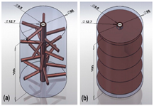 | [52] | |
| 7 | Y-fins; L1 = 0~11 mm; L2 = 0~28.5 mm; L3 = 4.5 mm; L4 = 28.5 mm; β = 13.4°~35.4°. | Single and double bifurcated Y-fins are proposed and geometrically optimized. | Double bifurcation increases discharge efficiency by about 24%; a smaller beta angle results in shorter run times. | 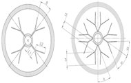 | [53] | |
| 8 | Five fins; Height is 0.2, 0.4, 0.6, 0.8 times pipe diameter; 0°, 45°, 60°, 72°. | Study of the effect of angle between fins on heat transfer performance. | Using fins concentrated at the bottom improves efficiency and reduces heat transfer time by up to 50%. |  | [54] | |
| 9 | New symmetrical fins. | Fills a gap in previous studies when buoyancy effects are present in the solidification process. | Efficiency increased by 14.3% with the addition of nano thermal conductive particles combined with fins. |  | [55] | |
| 10 | Eight V-shaped fins; The angle of the fin is 45°. | Study of the effect of V-fin and nanoparticles on heat transfer time in triplex-tube heat transfer. | The use of fins has a greater impact on heat transfer than the addition of nanoparticles. |  | [56] | |
| 11 | New V-fins. | The ice storage performance of V-shaped fins was compared with that of straight fins; the effects of V-shaped fin angle, length, and sub-width on ice storage were investigated. | The smaller length or width ratio of the V-fin has a shorter ice storage time. Compared to straight fins, V-shaped fins reduce the total ice storage time by 64.2%. | 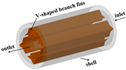 | [57] | |
| 12 | Bionic fins. | Proposed new annular and axial fins, design and optimization of tree branch bionic fins. | The radial fin design in Figure (a) has a tube spacing of 100 mm. The axial fin design with a tube spacing of 160 mm, as shown in Figure (b), was designed for longer charging and discharging times. The new axial fin design with a tube spacing of 70 mm, as shown in Figure (c). The Axial-70 fin design has a high power rate during the heat discharging of the storage unit. | 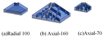 | [58] | |
| Thin rings | 1 | Thin ring thickness is 0.25, 0.5, 1, 2, and 3 mm. | Study of the effect of thin rings of different thicknesses on the rate of ice storage. | Thin ring tubes had a 34% higher ice storage rate than smooth tubes. |  | [47] |
| 2 | Single parallel; Double parallel; Staggered; The thickness is 0.25, 1, 2, 3 mm. | Study of the effect of the parameters of thin rings on the heat transfer time. | Staggering the thin rings and setting the thickness to 1 mm optimizes the overall heat transfer performance. |  | [48] |
| Main Factors | Numbers | Technical Approach | Main Contents | Main Conclusions | Ref. |
|---|---|---|---|---|---|
| Cold storage capacity | 1 | Cooling model optimization. | Taking four typical buildings as the research object, the influence of different control strategies and electricity price structures on the optimal ice storage rate was studied. | When the ice storage rate is less than 0.267, the cooler priority control strategy will be more appropriate to the optimized control strategy; when the ice storage rate is >0.35, the ice storage priority control strategy is more appropriate to the optimized control strategy. | [62] |
| 2 | Particle swarm optimization. | Outlines a study of load-shifting control strategies using different hot and cold energy storage facilities. | Load-shifting controls using building thermal mass can achieve more than a 30% reduction in daily peak loads and significant total cost savings from 8.5% to 29%. | [63] | |
| 3 | Model optimization. | A model-based optimal design method using genetic algorithms is developed to actively optimize the storage capacity. | Significant net annual cost savings of up to over USD 80,000 can be achieved by utilizing relatively small-scale active thermal and cooling energy storage systems, which is equivalent to 6.7% of a typical daily cooling load. | [64] | |
| A simulation-based approach to optimize the design of small-scale active energy storage systems in buildings to limit their power demand is proposed. | Demand-limiting controls using small storage tanks can save about 7% of a building’s total annual power consumption costs each year. The optimal storage capacity is less than 5% of the daily cooling load. | [65] | |||
| running cost | 1 | Forward dynamic programming algorithm. | An efficient model prediction controller for the charging and discharging of the ice storage part was developed (energy costs, equipment costs). | The model-predictive controller (MPC) receives tariff updates and re-optimizes the cooling system strategy according to the new prices. The open-loop optimal control does not have this information and operates the chiller at a very high price, resulting in operating costs that are approximately 40% higher. | [66] |
| 2 | Dynamic programming algorithm. | Discussing the optimization of the ice storage air conditioning system under the condition of considering the minimum life cycle cost and efficiency of ice storage tank. | In the ice priority mode, life cycle costs are lower than for a conventional air conditioning system from the fourth year of operation, and under the 10-year life cycle, nine ice-storage units with an ice charging rate of 36.2% incur minimum cost. | [67] | |
| The cost optimization analysis is carried out on the selection of cold storage equipment and chiller, and the influence of charge and discharge strategy and electricity price strategy on system operation is determined. | The optimal operating protocol for storage charging and discharging is determined by a dynamic programming method that minimizes the operating cost over an entire year. | [68] | |||
| 3 | Nonlinear programming methods. | A strategy based on mixed integer nonlinear programming is proposed to optimize the running schedule of building energy systems. | This strategy can significantly reduce operating energy costs (about 25%), reducing or even increasing to about 47% when using thermal energy storage systems. | [69] | |
| 4 | Model optimization. | Model-based real-time predictive optimal control of active and passive building thermal storage inventories in a test facility using time-of-use differentiated tariffs without demand charges is demonstrated. | When the optimal controller is given an imperfect weather forecast, the utility cost of the energy resource station can save 17% over the base case and 27% over the reference case. | [70] | |
| 5 | Mathematical modeling. | Optimized for life cycle economics. | Under the full load storage scenario and the base tariff structure, the daily savings would be USD 549.4/day, with the energy storage capital costs being paid off over 10 years, afterwards the daily saving in operational cost will be USD 4011.76/day. | [71,72] | |
| 6 | Neural network model. | Combination of neural network-based model prediction and genetic algorithm. | When time-of-use pricing or real-time pricing are adopted, the operating costs of district cooling networks are reduced by approximately 16% and 13%, respectively. | [73,74,75] | |
| 7 | Software modeling. | A model-based predictive control algorithm for cooling systems of small commercial buildings is proposed. | The proposed MPC algorithm can save about 5–20% per year, and the chiller priority strategy can save 20–30% per year. | [76] | |
| Operational Energy Consumption | 1 | Particle swarm optimization. | Study of system energy consumption and CO2 emissions. | The optimum capacity of the chiller is estimated to be 250 RT when the ice storage capacity is set to 1800 RT-h. | [77] |
| 2 | Model optimization. | A methodology is presented for determining the optimal chilled water storage (CWS) capacity and corresponding operating strategy for air conditioning loads at different electricity rates. | The optimal CWS strategy reduces peak demand by 38% under time-of-use (TOU) tariffs. Accordingly, customers can save 5.9% on operating costs. | [78] | |
| 3 | Strategy optimization. | The energy performance of a distributed energy system with a district cooling system (DES&DCS) was evaluated under four different control strategies. Comparisons were made with DCS and stand-alone cooling systems that are fully dependent on the grid. | Compared with the system that also adopts DCSs but only depends on the grid, the DES&DCS can save more than 10% of primary energy. Compared with the system that adopts an individual cooling system and only depends on the grid, the energy saving can be more than 16% and up to 19.1%. | [79] | |
| 4 | Software modeling. | Using EnergyPlus software modeling to validate a prediction methodology specifically designed to control multi-zone heating, ventilation, and air conditioning systems. | Regardless of the mode of operation (heating or cooling) and the time of year, energy consumption is significantly reduced by about 5 to 15%. | [80] | |
| Development of a dynamic computer model for ice thermal storage systems to compare energy use in conventional air-cooled systems and ice thermal storage systems. | Full ice storage can save up to 55% of the monthly cost of electricity needed for cooling compared to traditional air-cooling systems. Using the full storage option can reduce the total energy consumption of a selected building by up to 5%. | [81] | |||
| 5 | Mathematical modeling. | A detailed mathematical model is proposed for the combination of heating and cooling chemistries in district energy to achieve the best performance of the whole system. | Effective savings in total annual costs and CO2 emissions. More than 67% of the CO2 reductions are achieved by mixing heat and district cooling. | [82] | |
| External factors | 1 | Weather incorporated into the control system. | Consider the temperature parameters required for the indoor environment. | Significant increase in system operational capacity. | [83] |
| A novel HVAC control method is proposed to minimize energy consumption while maintaining comfortable indoor temperatures based on short-term future predictions from weather forecasting models. | Energy savings of up to 58.79% have been demonstrated in EnergyPlus simulations. | [84] |
Disclaimer/Publisher’s Note: The statements, opinions and data contained in all publications are solely those of the individual author(s) and contributor(s) and not of MDPI and/or the editor(s). MDPI and/or the editor(s) disclaim responsibility for any injury to people or property resulting from any ideas, methods, instructions or products referred to in the content. |
© 2025 by the authors. Licensee MDPI, Basel, Switzerland. This article is an open access article distributed under the terms and conditions of the Creative Commons Attribution (CC BY) license (https://creativecommons.org/licenses/by/4.0/).
Share and Cite
Guo, X.; Xu, X.; Wang, Z.; Chang, Z.; Chang, C. Research Progress on the Performance Enhancement Technology of Ice-on-Coil Energy Storage. Energies 2025, 18, 1734. https://doi.org/10.3390/en18071734
Guo X, Xu X, Wang Z, Chang Z, Chang C. Research Progress on the Performance Enhancement Technology of Ice-on-Coil Energy Storage. Energies. 2025; 18(7):1734. https://doi.org/10.3390/en18071734
Chicago/Turabian StyleGuo, Xinxin, Xiaoyu Xu, Zhixin Wang, Zheshao Chang, and Chun Chang. 2025. "Research Progress on the Performance Enhancement Technology of Ice-on-Coil Energy Storage" Energies 18, no. 7: 1734. https://doi.org/10.3390/en18071734
APA StyleGuo, X., Xu, X., Wang, Z., Chang, Z., & Chang, C. (2025). Research Progress on the Performance Enhancement Technology of Ice-on-Coil Energy Storage. Energies, 18(7), 1734. https://doi.org/10.3390/en18071734