Abstract
The low thermal conductivity of phase change materials (PCMs) limits their widespread application in practical energy storage systems. The integration of fins has emerged as an effective approach to enhance PCM melting rates. This study numerically investigates the effects of fin length and tilt angle variations on PCM melting processes through two-dimensional modeling. A rectangular container with vertical constant-power heating was simulated, which incorporated natural convection effects. Initially, the analysis of equal-length fins with varying dimensions revealed that longer fins and appropriate tilt angles could significantly accelerate the PCM melting. Subsequent investigation under constant total fin lengths demonstrated that two factors enhanced the heat transfer and reduced the melting duration: large fin length differences and the enclosed regions between the fins and the container bottom. Studies of extreme tilt angles during angular variation indicated that the configuration with a 30 mm length difference with limit angles could positively affect the melting performance. The findings offer valuable insights for the optimal design of phase change energy storage systems.
1. Introduction
Against a carbon reduction background, the application of renewable energy has become a trend in industrial development, including solar energy. Due to the fact that solar energy can only be collected and applied during the daytime, it is necessary to combine energy storage technology to prolong its utilization duration and thus to improve its working efficiency [1,2]. Energy storage mainly includes the storage of electricity, hydrogen, and thermal energy. Among them, the cost of thermal energy storage is relatively low, hence it has become a focused research field.
Latent heat thermal energy storage (LHTES) achieves superiority in thermal storage technology due to its high storage density and stable storage temperature and thus has been applied in battery thermal management systems [3,4], waste heat recovery systems [5,6], building energy management systems [7,8], vehicle cooling [9,10], and solar stills [11,12]. However, the low thermal conductivity of phase change materials limits its storage rate and efficiency. In this regard, a common way to improve this is to insert fins into the storage installation. The existing literature has usually concentrated on the design of fins, mainly including materials, quantities, lengths, arrangements, and shapes.
Tian et al. [13] studied the effect of fin material in the research of PCM melting in a rectangular enclosure. Compared with the no-fin condition, the melting time was decreased by 41.6%, 41.0%, 40.1%, and 37.2% by inserting copper, aluminum, carbon steel, and steel 302 fins, respectively. However, among these materials, aluminum was recommended as the best fin material after evaluation regarding stored energy per mass and cost per energy stored. Rawat et al. [14] selected copper, aluminum, and carbon steel as the materials of T-shaped fins. They installed double fins on the side of the storage container and evaluated the effect of the size and the materials of the T-shaped fins on the melting rate. The results showed that the ratio between the length of the upper fin and the lower fin will weaken the melting rate, and the maximum reduction of the melting time is achieved by the copper material, 48.36% less than the no-fin PCM enclosure.
For T-shaped fins, Rawat et al. [15] also found for the same fin area that PCM melting with two regular fins was faster compared to two T-shaped fins. However, the fastest melting rate was achieved by a single T-shaped fin with the longest length and positioned in the lower part of the container. Wang et al. [16] designed fins with an “L” shape. Dimensions of vertical (LV) and horizontal (LH) parts were considered as the varying parameters. The best melting performance was achieved by the design of LH of 40 mm and LV of 20 mm, presenting about 45% enhancement compared to the conventional double 30 mm fins. Bianco et al. [17] applied a density-based topology method to optimize the fins for enhancing the melting of PCM. The conventional fins were converted into tree-like shapes. When heated with a temperature of 44 °C, compared with the plate fin, the optimized fins showed a significant effect on reducing the melting duration by 62.5%.
The effects of fin specifications, such as the quantity, length, and thickness of fins, were investigated in Hosseinizadeh et al.’s research [18]. In their experimental and numerical work, they found that the fin quantity and fin length were more effective than the fin thickness, and they also indicated a saturated fin thickness above which the melting process cannot be further improved. They also found, during the melting process, that natural convection could enhance the melting process. In the research of Abdi et al. [19], they installed fins vertically in an aluminum container heated from the bottom. By varying the fin quantity from 0 to 5, and the fin length from 0.25 to 0.75 of the container height, they found that a vertical arrangement of fins does not suppress the natural convection compared with horizontal fins. In the case with long fins, by heating with a constant temperature, the mean power absorbed could be elevated by about 200%, although the amount of PCM in the container was reduced by 12% due to the installation of fins. Wu et al. [20] embedded a single fin in a square container to study the effect of fin length and position on the melting and solidification processes of PCM separately. The results showed the total melting time was reduced obviously with a longer fin and a lower position. Conversely, they found a higher fin position could encourage solidification. Oliveski et al. [21] analyzed the effect of fin aspect ratio and fin position in the melting and solidification process in a rectangular cavity. Four fin aspect ratios and three positions were applied during the study. Results indicated that fins with a higher aspect ratio showed better performance than those with a lower aspect ratio, and a 16% difference was achieved when positioned in the lower part of the cavity; however, the solidification processes were almost independent of the fin position. Cui et al. [22] enhanced the melting rate of the PCM by positioning fins off the heating surface, and for the top-heated condition, the melting duration was reduced by 8.2%.
PCM melted in a vertical heated container embedded with double fins was investigated by Ji et al. [23]. The ratio between the fin lengths of the upper fin and lower fin was found to lower the melting rate, and with a length ratio at 0.25, the total melting time can be reduced by about 25% based on the equal length scheme. They attributed the enhancement to intensified natural convection. Ji et al. [24] continued to assess melting rate enhancement by using fins with an inclined angle ranging from −30° to +30°. The shortest melting time was achieved by the fins of −15°, reduced by 23.8% compared with the fins of 0°. They found, for the longer fin lengths, that fins of −15° could modify the non-uniform temperature distribution and enhance the melting rate by 62.7%. Qin et al. [25] experimentally validated the hypothesis that angled metallic fins could enhance the melting rate for a sidewall-heated cubic container, proposed in the previous work. Compared to the conventional horizontal fins, fins with angles of +30° and +15° prolonged the melting time by 4.0% and 3.8%, respectively. For the fins of −15° and −30°, the melting time could be reduced by up to 5.2%.
From the literature review, it can be seen that diverse research has been performed on finned enhancement of PCM melting rate, mainly aiming to expand the heat transfer area, improve thermal conductivity, and promote the enhancement of natural convection. Recent research has mainly focused on the design of non-uniform fin lengths (e.g., Ji et al. [23]) or inclined angles (e.g., Ji et al. [24]). As mentioned in these references, the PCM melts slower in the lower section of a rectangular container or cavity. Thus, the researchers prolonged the fin length in the lower section or inclined the fin angle downwards. However, they did not concentrate on the section of the corner of the container where the PCM is normally the last to melt. Thus, in this paper, we designed the fins by integration of these two aspects to include the corner by varying the inclined fin angle from 0° to its maximum by which it can touch the bottom of the container or prolonging the length of the fin to reach the corner of the container. The optimal combination was found, and the mechanism was investigated and elaborated. The findings in this work will be helpful for fin design applied in LHTES systems.
2. Description of Numerical Model
2.1. Physical Model
As shown in Figure 1, a two-dimensional physical model was proposed to simulate the melting process of PCM in a square cavity with dimensions of 100 × 100 mm (length × height). In Ji et al.’s work [24], 1.5–3.5 W/m2 was applied to study the heating power effect on PCM melting with inclined fins and indicated a narrowing discrepancy between the angled fins for the higher heating power. Thus, in this research, a constant heating power of 2.5 kW/m2 was selected and applied to the side wall. And, similar to their model, the other 3 walls were set as adiabatic. In this research, two equidistantly distributed 2 mm thick copper fins were attached to the left wall of the cavity. The effects of the fin tilt angle and length on the melting behavior were systematically investigated. The PCM used in this study was RT42 with a melting temperature range of 38–42 °C. Table 1 summarizes the thermophysical properties of RT42 and copper in this work. To simplify the numerical calculation, the following assumptions were employed:
- (1)
- The thermophysical properties of PCM and fins are assumed as constant;
- (2)
- The PCM RT42 is considered as an incompressible fluid and is adherent to Boussinesq approximation;
- (3)
- Viscous dissipation occurring in the liquid PCM is ignored;
- (4)
- The volume variation in the phase change process is not considered;
- (5)
- The heating resistance at the heating surface is neglected.
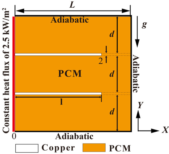
Figure 1.
Numerical configuration and boundary condition of the physical model.

Table 1.
Thermal and physical properties of the materials [24].
Table 1.
Thermal and physical properties of the materials [24].
| Property | RT42 | Copper |
|---|---|---|
| Density of solid ρs (kg/m3) | 880 | 8978 |
| Density of liquid (kg/m3) | 760 | |
| Heat capacity (J/kg·K) | 2000 | 381 |
| Latent heat (kJ/kg) | 165 | |
| Thermal conductivity k (W/m·K) | 0.2 | 387.6 |
| Dynamic viscosity (kg/m·s) | 0.0235 | |
| Melting temperature Tl (°C) | 42 | |
| Solid temperature Ts (°C) | 38 | |
| Thermal expansion coefficient β (K−1) | 0.0001 |
2.2. Governing Equations
Regarding the PCM melting process, the liquid PCM motion was assumed to be laminar, unsteady, and incompressible. The volume change during the solid-to-liquid phase transition was considered negligible, and the motion of solid PCM was disregarded in the simulation. The following thermophysical properties of PCM were treated as constants: thermal conductivity, viscosity, and specific heat. Natural convection was considered to dominate the heat transfer once sufficient PCM melted into the liquid phase. Boussinesq approximation was invoked to account for density variations induced by buoyancy forces, and it is specifically applicable to thermally driven flow conditions. The continuity equation, momentum equation, and energy equation used for the simulation are
where ρ is the density, is the velocity vector, H is the enthalpy, P is the pressure, μ is the dynamic viscosity, k is the thermal conductivity, and is the gravitational acceleration, which was set to 9.8 m/s2. Due to the reduced porosity in the mushy region, the source term in the momentum equation takes the following form:
where , the mushy zone constant, measures the amplitude of the damping. The higher this value, the steeper the transition of the velocity to zero when the material solidifies. It varies from to and is set at in this paper, where ε is a small value to prevent division by zero and was set to 0.001 in this study. β is the liquid fraction and characterizes the phase transition between solid and liquid when the temperature is in the range (TS < T < TL). It is defined as:
where TS is the temperature at which the solid phase begins to melt, and TL is the temperature at which the material fully transitions into the liquid phase.
The enthalpy H in the energy equation is computed as the sum of the sensible and latent enthalpy,
and the sensible enthalpy h can be expressed as
where is the reference enthalpy at the reference temperature , and is the specific heat. The latent enthalpy ΔH can be written in terms of the latent heat of the material ,
which changes between zero (for a solid) and (for a liquid), as 0 < < 1. The heat transfer process in the metallic fins is expressed as:
The governing equations proposed above were solved by using the software COMSOL Multiphysics 6.0. The non-linear time-dependent solver and the consistent Newtonian iteration scheme were selected for the simulation, with eight iterations for each time step. To guarantee convergence robustness, the damping factor was fine-tuned to 0.9. Moreover, a rigorous tolerance threshold of 0.001 was used to preserve the precision of the solution. The initial temperature was set to 298.15 K, the initial pressure was set to 1 atm, and the heating power at the bottom surface was maintained constant at 2500 W/m2.
2.3. Grid and Time Step Independence Tests
To mitigate the influence of the grid resolution and temporal discretization on the numerical accuracy, as shown in Figure 2 a grid independence study was conducted for the finned configuration for three mesh sizes: 8757 elements, 15,438 elements, and 31,929 elements. Time steps of 0.5, 1, and 2 s were also tested to identify the optimal temporal resolution. The resulting curves in Figure 3 show a similar relationship with the grid test. Through comparative analysis, the configuration with 15,438 elements and a 1 s time step were selected for this study to balance computational efficiency and solution accuracy. Figure 4 shows the mesh grid with 15,438 elements.
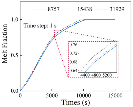
Figure 2.
Mesh size independence analysis.
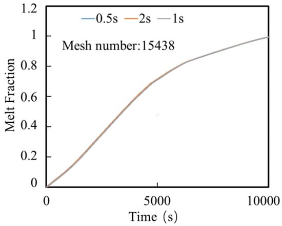
Figure 3.
Time step size independence analysis.
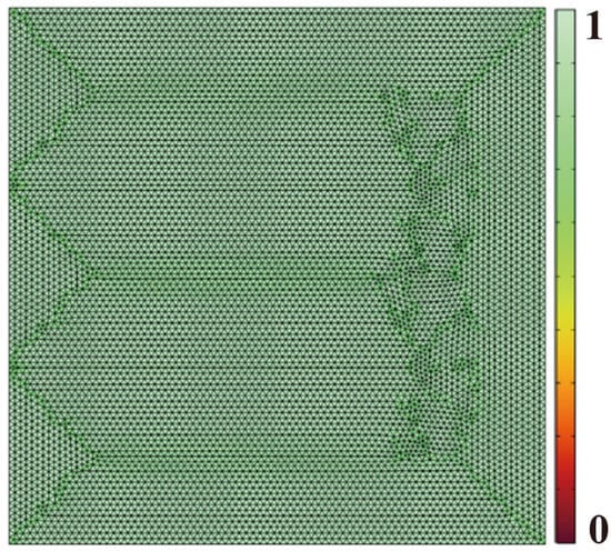
Figure 4.
The quality of the mesh grid for the simulation.
2.4. Model Verification
To validate the developed simulation model, preliminary simulations were performed and compared against experimental tests conducted by Kamkari et al. [25] and the simulation results from Ji et al. [24]. The experimental work focused on the dynamic behaviors of the PCM melting in a rectangular enclosure at various inclination angles. Lauric acid was used as the PCM, and one set of their experiments with the enclosure inclination angle of 90° and input wall temperature of 70 °C were chosen for the validation of the present simulation. By using the material properties and the geometry of the container given in the experimental work, the simulation results as shown in Figure 5 generally agreed with the experimental results. The observed minor discrepancies may be attributed to temperature-dependent variations in the thermophysical properties of the PCM during experimental testing. Furthermore, comparing the evolving liquid contours at different stages shown in Figure 6, the tiny difference may lie in the mesh settings. Consequently, the developed numerical model was proved valid for simulating phase change thermal energy storage.
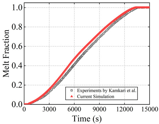
Figure 5.
Comparison with melt fraction results of Kamkari et al. [26].
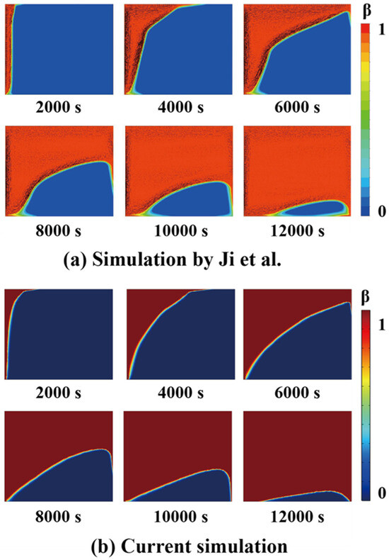
Figure 6.
Melting evolution simulated by Ji et al. [24] (a) and the current work (b).
3. Results and Discussion
3.1. Effects of the Total Fin Length and Inclination Angle Variation
To investigate the impact of the fin geometry on the phase change dynamics, numerical simulations were conducted for configurations that featured two identical fins with lengths of 20, 40, and 60 mm under varying inclination angles. Figure 7 summarizes the total melting duration for these configurations. The results reveal a positive correlation between total fin length and melting rate: longer fins exhibited accelerated phase change processes. The influence of the inclination angle became more pronounced with increasing fin length, as evidenced by steeper slopes in the melting duration curves. For the 60 mm fins, the melt duration was shortened by 6.1%.
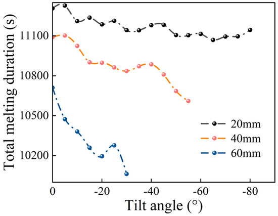
Figure 7.
Total melting duration for each angle at equal fin lengths.
The optimal inclination angles were identified as 65°, 55°, and 30° for fins of 20, 40, and 60 mm, respectively. For the 40 mm and 60 mm configurations, these optimal angles coincide with their maximum allowable downward inclination angles under the tested conditions. Thus, the heat transfer efficiency at larger inclination angles may be enhanced by improving the convective flow patterns and increasing the interfacial contact area between the fins and the PCM.
Figure 8a shows the melting process reached 0.4 for the fins with a tilt angle of 25° and different lengths (20, 40, and 60 mm). The liquid fraction had completely enveloped the 20 mm fin. Beyond this point, the fin contributed minimally to the system melting, which resulted in relatively low heat transfer efficiency, thus the shorter fin requires a longer melting time (approximately 2976 s) to reach this fraction. Compared to 20 mm fin, only a large portion of the fin became wrapped by the liquid phase for the 40 mm fin, and the liquid expansion was accelerated, which reduced the melting time to 2942 s. For the 60 mm fin, a large part of the fin was covered with thin liquid. The expansion of the liquid nearly reached the maximum extent of the fin, and the melting time further decreased to 2898 s, which is the shortest among the three examined fin lengths.
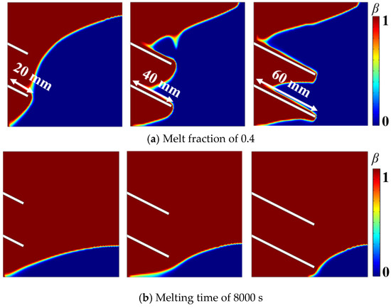
Figure 8.
Liquid phase distribution at various stages for different fin lengths.
Figure 8b illustrates the distribution of the liquid phase fraction in the later stages of melting at 8000 s. The solid phase in the lower right corner was more resistant to melting. Longer fins, due to their increased effective tilt (i.e., a larger tilt angle relative to the hard-to-melt region), were positioned closer to this region, which amplified the effect of the tilt angle. Consequently, the relative change in distance during the tilting process is more pronounced for longer fins and more significantly impacts on the melting behavior.
The region in the lower right section of the container consistently exhibited delayed melting, which suggests that the continued use of fins with uniform lengths may result in a suboptimal utilization of the heat transfer capability of upper fins. This phenomenon is primarily attributed to the driving effect of natural convection: when the higher-temperature liquid phase change material ascends after melting, the temperature in the upper region rapidly increases, whereas the phase change material in the lower region remains below the melting point. Under these circumstances, an important question arises: Can extending the length of the lower fins while maintaining the total fin length yield a beneficial effect on the overall phase change process?
To investigate this topic, the optimized design was divided into three groups with different fin configurations. In the first group, both fins measured 75 mm in length; in the second group, the fin lengths were 60 and 90 mm; in the third group, the fin lengths were 50 and 100 mm. In all three configurations, the combined fin length was maintained at 150 mm. The fins were rotated downward by various angles using the apex of each fin as the center of rotation.
Figure 9 and Figure 10 show the melting curves and the melting process of the PCM. As indicated in Figure 10, initially at t = 2000 s, the PCM surrounding the fins began to melt due to thermal conduction. At t = 4000 s, the onset of natural convection induced a flow of the liquid PCM. At 6000 and 8000 s, the PCM in the inter-fin regions became fully melted, and the influence of the fins on the melting process gradually diminished. In all cases, the evolution of the solid–liquid interface of the PCM depended on the fin orientation: when the fins were horizontal, they were enclosed by the melted PCM at 8000 s, whereas for the inclined fins, especially for the fins with length differences, part of their length was surrounded by melted PCM. On this occasion, the fins with both an inclined angle and length difference still worked well in the melting and accelerated the melting of the PCM in the lower region of the container.
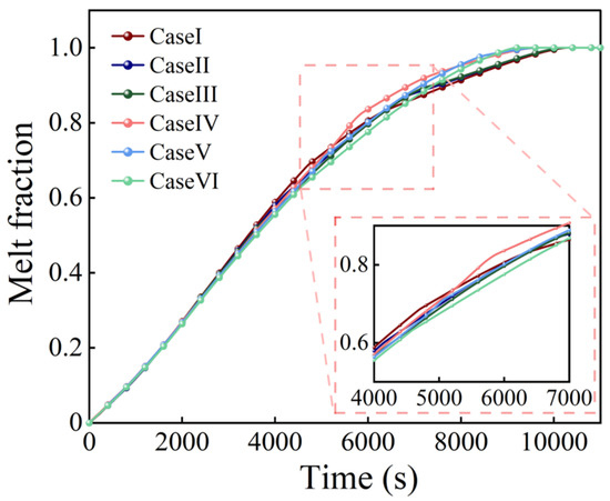
Figure 9.
Melt fraction curves for different fin designs with identical total fin lengths.
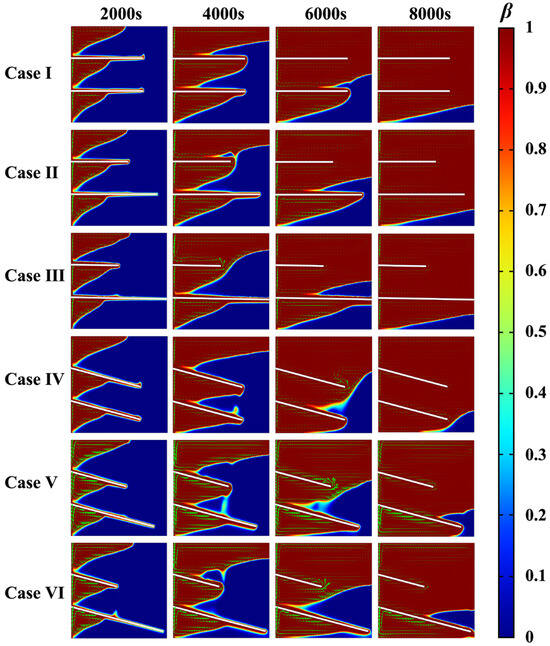
Figure 10.
Melting process for different fin designs with identical total fin length.
Figure 11 illustrates the relationship between the complete melting time and the fin inclination angle for configurations with fin length differences of 0, 30, and 50 mm. When the tilt angle increased, the complete melting time for the 0 mm and 30 mm cases remained relatively stable over the entire range of angles with only a noticeable decrease at the maximum tilt angle. In contrast, the curve for the 50 mm length difference first decreased and subsequently increased with the minimum melting time at a tilt angle of 13°. This behavior is attributed to the gradual optimization of the available space for bottom melting due to the progressive adjustment of the lower fin’s angle, whereas the influence on the natural convection in the upper region remained minimal. Due to the combined effect of these two mechanisms, an optimal tilt angle relative to the 0 mm configuration led to a maximum improvement of approximately 7%, as depicted in Figure 12. Compared with the horizontal fins with equal length, the enhancement is 12.3%.
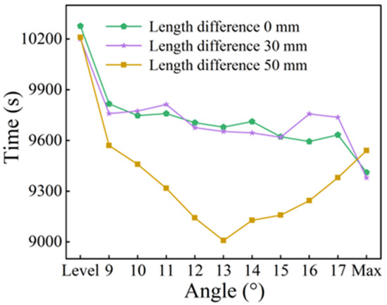
Figure 11.
Complete phase change time at different angles.
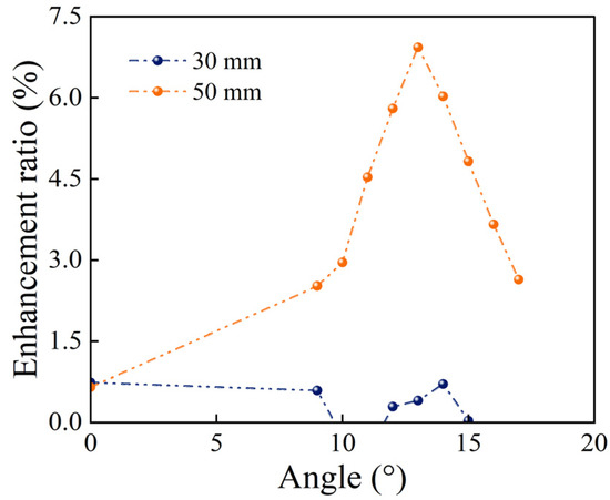
Figure 12.
Enhancement rate relative to the 0 mm length difference.
Figure 13 and Figure 14 depict the temporal evolution of both the maximum temperature at the heating surface and average temperature at the PCM surface under varying fin length differences (0, 30, and 50 mm) and tilt angles (0° and 15°). Regardless of whether one considers the maximum heating surface temperature or the average PCM surface temperature, the horizontal fin configuration (0° tilt) exhibited higher temperatures after 4000 s. As previously discussed, under horizontal conditions, the phase change proceeds more slowly. This slower melting process results in an uneven distribution of heat in the system, which more rapidly increases the temperature. In this context, the latent heat is released as sensible heat and increases the heating surface temperature.
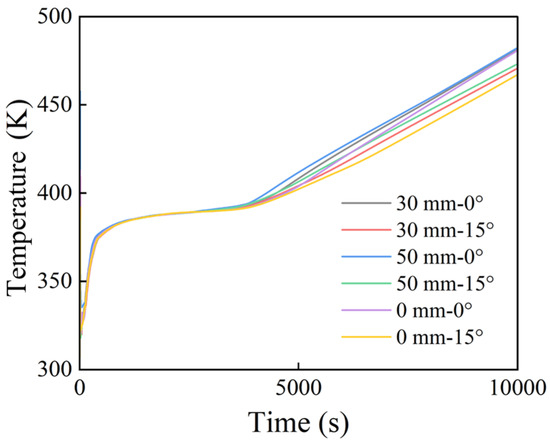
Figure 13.
Maximum temperature on the heating surface.
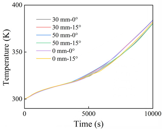
Figure 14.
Average temperature of PCM.
The curves for the maximum temperature and average PCM surface temperature reveal that configurations with a larger fin length difference tend to exhibit higher maximum temperatures. The reason may be that, when the fin length difference is small, the disparity in heat transfer between the two fins is minimal. Conversely, a larger fin length difference induces significant disparities: the shorter fin transfers heat in a more concentrated manner, which leads to a higher peak temperature.
3.2. Effects of the Limit Tilt Angle on the Melting Rate
Based on the preceding studies, when the fin tilt angle was gradually varied, the extension of the lower fin increased its likelihood of contacting the container boundary. At a certain limit tilt angle, the fin formed an enclosed region with the container. This section investigates the impact of the fin contacting the melt pool bottom in the melting process of the PCM. The results indicate that, under certain conditions (e.g., for a 30 mm fin length difference), the enclosed state formed upon contact between the fin and the melt pool bottom can increase the local flow velocity along the fin surface, enhance natural convection, and reduce the overall PCM melting time. However, under other conditions, the formation of an enclosed region may impede the melting process. The following discussion will examine in depth the mechanisms by which this enclosed state affects the PCM melting behavior.
Figure 15 visualizes the melting process in different fin configurations. Cases VII and VIII correspond to a fin length difference of 30 mm with tilt angles of 15° (suboptimal configuration) and the limit tilt angle (optimal configuration), respectively. Cases IX and X correspond to a fin length difference of 50 mm with tilt angles of 13° (the optimal configuration) and the limit tilt angle. These visualizations encompass the liquid phase distribution and velocity vector fields at three distinct liquid phase fractions. The limit tilt angles for Cases IX and X were 21° and 19°, respectively.
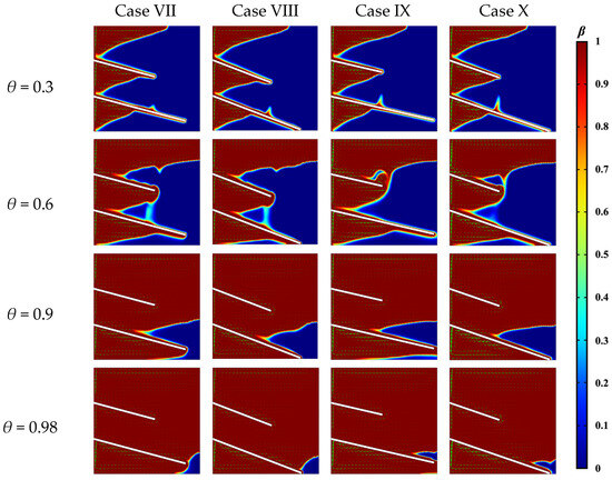
Figure 15.
Liquid phase and velocity distribution for limit angle vs. non-limit angle.
Cases VII and VIII had similar solid–liquid interface contours for the two tilt angles at a liquid phase fraction of 0.3. However, when the liquid phase fraction reached 0.6, a marked difference was observed: the solid PCM under the lower fin in the enclosed region (as observed in Case VIII) melted significantly faster. At a liquid phase fraction of 0.9, the solid PCM under the lower fin in Case VII remained partially unmelted. At a liquid phase fraction of 0.98, although the final remaining unmelted portion in both cases was confined to the lower right corner, the solid PCM under the lower fin in Case VIII had completely melted. This enhanced melting occurred because convective heat transfer more effectively promotes the melting of the PCM above the fin, which yielded a higher overall melting rate in Case VIII.
At liquid phase fractions of 0.3 and 0.6, the melting behavior in Cases IX and X was similar to that observed in Cases VII and VIII. However, when the liquid phase fraction reached 0.9, Case IX exhibited two distinct liquid regions: one above and one below the lower fin, whereas Case X maintained a single, contiguous unmelted region. At a liquid phase fraction of 0.98, only minimal amounts of PCM remained unmelted in Case IX, which were localized in the upper fin region and near the lower edge. In this case, the upper residual PCM was particularly limited, rapidly melts due to upward convection, and resulted in a shorter overall melting time. In contrast, in Case X, a small amount of solid PCM persisted to the right of the lower fin; since this region primarily relies on conductive heat transfer for melting, its melting rate was comparatively slower.
Figure 16 presents the surface maximum velocity profiles for Cases VII–X. The velocity generally increased before 5000 s, reached a peak at approximately 5000 s, and subsequently gradually decreases. Considering the liquid phase fraction curves in Figure 17, the period of 5000–8000 s corresponded to the transition phase during which the liquid phase fraction increased from 0.6 to 0.9. During this phase, detailed comparisons of Cases VII and VIII and Cases IX and X reveal that the maximum surface velocity was consistently higher for the configurations at the limit tilt angle. Thus, the enhanced convective flow in these cases enhanced the overall melting process by 2.5%. Table 2 shows the melt duration for different cases, which clearly demonstrates the effect of different angles, length differences, and extreme inclinations.
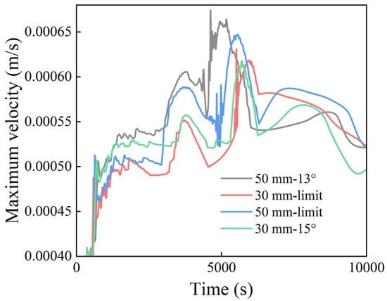
Figure 16.
Maximum velocity evolution during the melting process.
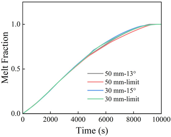
Figure 17.
Melt fraction curves regarding fin length difference and tilt angle.
Table 2.
Phase transition times for different cases.
4. Conclusions
In this study, a comprehensive numerical analysis was conducted to investigate the effects of various fin geometric parameters on the melting process of PCM. The study focused on the combined influence of the fin length differences, tilt angles, and formation of enclosed regions. The key findings were as follows.
- The tilt angle of the fins significantly impacted the melting rate. When the tilt angle increased, the melting rate of the PCM in the lower regions was enhanced. This effect was particularly pronounced with longer fin configurations, and the melting rate can be enhanced by up to 6.1%.
- When the total fin length was constant, fins with a larger length difference were more effective at promoting the melting of the lower regions, especially when an appropriate tilt angle was applied. Compared with the horizontal fins of equal length, the melt duration can be reduced by 12.3%.
- When the fins tilted to the limit angle, creating an enclosed space, the flow velocity increased and the convective heat transfer was strengthened, which could reduce the overall melting time by about 2.5%.
The findings in this research will be helpful for fin designs in a rectangular container for LHTES, especially for the lateral heating condition with a moderate flux.
Author Contributions
Conceptualization, software, and writing—original draft, X.Z.; Supervision, writing—review and editing, W.C.; Validation, S.Y. and Z.W.; Funding acquisition Z.X.; Supervision, S.Z. All authors have read and agreed to the published version of the manuscript.
Funding
This research was funded by the National Natural Science Foundation of China (No. 52006023), the Fundamental Research Funds for the Central Universities (No. 3132023223), and the College Students’ Innovation and Entrepreneurial Training Plan Program (No. 202310151114).
Data Availability Statement
The data presented in this study are available on request from the corresponding author.
Conflicts of Interest
The authors declare no conflicts of interest.
References
- Cui, W.; Guo, T.; Yuan, X.; Ma, H.; Liang, D.; Dong, J. Experimental study on the supercooling and heat transfer performance during the solidification of sodium acetate trihydrate composites. Sol. Energy Mater. Sol. Cells 2023, 250, 112098. [Google Scholar] [CrossRef]
- Kapsalis, V.; Karamanis, D. Solar thermal energy storage and heat pumps with phase change materials. Appl. Therm. Eng. 2016, 99, 1212–1224. [Google Scholar] [CrossRef]
- Huang, P.; Wei, G.; Cui, L.; Xu, C.; Du, X. Experimental and numerical optimization of cascaded PCM heat sink by using low melting point alloys. Energy Convers. Manag. 2022, 269, 116149. [Google Scholar] [CrossRef]
- Javani, N.; Dincer, I.; Naterer, G.F.; Yilbas, B.S. Exergy analysis and optimization of a thermal management system with phase change material for hybrid electric vehicles. Appl. Therm. Eng. 2014, 64, 471–482. [Google Scholar] [CrossRef]
- Merlin, K.; Soto, J.; Delaunay, D.; Traonvouez, L. Industrial waste heat recovery using an enhanced conductivity latent heat thermal energy storage. Appl. Energy 2016, 183, 491–503. [Google Scholar] [CrossRef]
- Xu, H.; Romagnoli, A.; Sze, J.Y.; Py, X. Application of material assessment methodology in latent heat thermal energy storage for waste heat recovery. Appl. Energy 2017, 187, 281–290. [Google Scholar] [CrossRef]
- Jaworski, M. Thermal performance of building element containing phase change material (PCM) integrated with ventilation system-an experimental study. Appl. Therm. Eng. 2014, 70, 665–674. [Google Scholar] [CrossRef]
- Rouault, F.; Bruneau, D.; Sebastian, P.; Nadeau, J.P. Use of a latent heat thermal energy storage system for cooling a light-weight building: Experimentation and co-simulation. Energy Build. 2016, 127, 479–487. [Google Scholar] [CrossRef]
- Nicolalde, J.F.; Cabrera, M.; Martínez-Gómez, J.; Salazar, R.B.; Reyes, E. Selection of a phase change material for energy storage by multi-criteria decision method regarding the thermal comfort in a vehicle. J. Energy Storage 2022, 51, 104437. [Google Scholar] [CrossRef]
- Mat, S.; Al-Abidi, A.A.; Sopian, K.; Sulaiman, M.Y.; Mohammad, A.T. Enhance heat transfer for PCM melting in triplex tube with internal–external fins. Energy Convers. Manag. 2013, 74, 223–236. [Google Scholar] [CrossRef]
- Sangeetha, A.; Shanmugan, S.; Alrubaie, A.J.; Jaber, M.M.; Panchal, H.; Attia ME, H.; Elsheikh, A.H.; Mevada, D.; Essa, F.A. A review on PCM and nanofluid for various productivity enhancement methods for double slope solar still: Future challenge and current water issues. Desalination 2023, 551, 116367. [Google Scholar] [CrossRef]
- Shalaby, S.M.; El-Bialy, E.; El-Sebaii, A.A. An experimental investigation of a V-corrugated absorber single-basin solar still using PCM. Desalination 2016, 398, 247–255. [Google Scholar] [CrossRef]
- Tian, L.; Liu, X.; Chen, S.; Shen, Z. Effect of fin material on PCM melting in a rectangular enclosure. Appl. Therm. Eng. 2020, 167, 114764. [Google Scholar] [CrossRef]
- Rawat, P.; Ashwni, A.F.; Sherwani, A.F. A numerical study on the impact of fin length arrangement and material on the melting of PCM in a rectangular enclosure. Int. J. Heat Mass Transf. 2023, 205, 123932. [Google Scholar] [CrossRef]
- Rawat, P.; Goyal, A.; Sherwani, A.F. A comparative numerical study about the impact of rectangular and T shaped fins on melting of PCM in a rectangular enclosure. Appl. Therm. Eng. 2023, 228, 12046. [Google Scholar] [CrossRef]
- Ao, C.; Yan, S.; Hu, W.; Zhao, L.; Wu, Y. Heat transfer analysis of a PCM in shell-and-tube thermal energy storage unit with different V-shaped fin structures. Appl. Therm. Eng. 2022, 216, 119079. [Google Scholar] [CrossRef]
- Bianco, N.; Fragnito, A.; Iasiello, M.; Mauro, G.M. Design of PCM-based heat sinks through topology optimization. J. Phys. Conf. Ser. 2023, 2509, 012001. [Google Scholar] [CrossRef]
- Hosseinizadeh, S.F.; Tan, F.L.; Moosania, S.M. Experimental and numerical studies on performance of PCM-based heat sink with different configurations of internal fins. Appl. Therm. Eng. 2011, 31, 3827–3838. [Google Scholar] [CrossRef]
- Abdi, A.; Martin, V.; Chiu, J.N.W. Numerical investigation of melting in a cavity with vertically oriented fins. Appl. Energy 2019, 235, 1027–1040. [Google Scholar] [CrossRef]
- Wu, J.; Chen, Q.; Zhang, Y.; Sun, K. Phase change material heat transfer enhancement in latent heat thermal energy storage unit with single fin: Comprehensive effect of position length. J. Energy Storage 2021, 42, 103101. [Google Scholar] [CrossRef]
- Oliveski, R.D.C.; Tacques Filho, A.D.Q.; Schroer, I.A. Melting and solidification in thermal storage: Influence of fin aspect ratio and positioning in a full charging and discharging cycle. J. Energy Storage 2022, 50, 104303. [Google Scholar] [CrossRef]
- Cui, W.; Zhang, S.; Zhang, J.; Fan, H.; Zhang, X. Numerical investigation on the melting delay of PCM top heated with a constant heat flux. Int. Commun. Heat Mass Transf. 2025, 163, 108779. [Google Scholar] [CrossRef]
- Ji, C.; Qin, Z.; Dubey, S.; Choo, F.H.; Duan, F. Simulation on PCM melting enhancement with double-fin length arrangements in a rectangular enclosure induced by natural convection. Int. J. Heat Mass Transf. 2018, 127, 255–265. [Google Scholar] [CrossRef]
- Ji, C.; Qin, Z.; Low, Z.; Dubey, S.; Choo, F.H.; Duan, F. Non-uniform heat transfer suppression to enhance PCM melting by angled fins. Appl. Therm. Eng. 2018, 129, 269–279. [Google Scholar] [CrossRef]
- Qin, Z.; Low, Z.; Ji, C.; Duan, F. Efficacy of angled metallic fins for enhancing phase change material melting. Int. Commun. Heat Mass Transf. 2022, 132, 105921. [Google Scholar] [CrossRef]
- Kamkari, B.; Shokouhmand, H.; Bruno, F. Experimental investigation of the effect of inclination angle on convection-driven melting of phase change material in a rectangular enclosure. Int. J. Heat Mass Transfer 2014, 72, 186200. [Google Scholar] [CrossRef]
Disclaimer/Publisher’s Note: The statements, opinions and data contained in all publications are solely those of the individual author(s) and contributor(s) and not of MDPI and/or the editor(s). MDPI and/or the editor(s) disclaim responsibility for any injury to people or property resulting from any ideas, methods, instructions or products referred to in the content. |
© 2025 by the authors. Licensee MDPI, Basel, Switzerland. This article is an open access article distributed under the terms and conditions of the Creative Commons Attribution (CC BY) license (https://creativecommons.org/licenses/by/4.0/).