Article

Sulfur Emission Dependence on Various Factors During Biomass Combustion

by
Giedrius Jomantas
1,*,
Kęstutis Buinevičius
1 and
Justas Šereika
2
1
Department of Energy, Faculty of Mechanical Engineering and Design, Kaunas University of Technology, 51424 Kaunas, Lithuania
2
Laboratory of Heat Equipment Research and Testing, Lithuania Energy Institute, 44403 Kaunas, Lithuania
*
Author to whom correspondence should be addressed.
Energies 2025, 18(7), 1701; https://doi.org/10.3390/en18071701
Submission received: 11 February 2025 / Revised: 20 March 2025 / Accepted: 21 March 2025 / Published: 28 March 2025
(This article belongs to the Section A4: Bio-Energy)

Abstract

:
The transition from fossil fuels to renewable energy sources often requires shifting toward biomass fuels such as agriculture residues and waste, which tend to emit higher emission rates during combustion, and one of them is sulfur compounds. The main objective of this study is to clarify the regularities of the formation of sulfur compounds depending on the technological factors when burning sulfur-containing biomass. The experiments were conducted on two experimental stands—models of 20 kW and 25 kW capacities of industrial boilers equipped with reciprocating grates—by burning sunflower husk pellets and meat bone meal. The influence of incomplete combustion (indicator CO concentration), flue gas recirculation, and combined effects of both factors on concentrations of SO2, SO3, and H2S were investigated during experiments. In addition, 20–90% of the sulfur in the fuel is converted to SO2, contingent upon the combustion conditions. These findings have practical implications for the design and operation of biomass combustion systems. The highest SO2 emissions were observed when primary air was mixed with flue gas recirculation and at the highest content of CO. The correlation of SO2 and SO3 and SO2 and H2S concentrations in flue gases of boilers was investigated. The conversion ratio of SO2 to SO3 was determined under different combustion modes and showed that this ratio can reach up to 5%. The sulfur content in ash deposits in different areas of the actual industrial boiler was analyzed. The highest percent of sulfur (S = 20%) in ash was found on the first boiler pass.

1. Introduction

The use of biomass in combustion processes is increasingly important as it offers a more economical, sustainable, and renewable energy source compared to fossil fuels. However, it is known that during biomass combustion, a number of pollutants resulting from both complete and incomplete combustion, e.g., sulfur oxides (SOx), nitrogen oxides (NOx), carbon monoxide (CO), hydrocarbons, and particular matter [1], are found in the flue gas. Emissions of SO2, NOx, and particulate matter are limited according to European standards: EU Directive 2015/2193 [2] is for sources of pollution up to 50 MW and 2010/75/ES [3] for sources over 50 MW. According to EU Directive 2015/2193, SO2 must not exceed 200 mg/m3 for biomass combustion and 400 mg/m3 for other solid fuels. According to 2010/75/ES, SO2 must not exceed 200 mg/m3 in the region of 50–300 MW of total pollution sources and 150 mg/m3 for emission sources exceeding the total capacity of 300 MW for biomass combustion.
Sulfur oxides are among the most undesired pollutants contributing to atmospheric pollution, equipment corrosion, and deposit formation within the boiler [4]. When the concentration reaches its dew point, a mixture of sulfuric and sulfurous acids can condense on heat exchangers (boilers, economizers), ducts, dampers, fly ash separators, and stacks. This corrosion and the resulting acid condensate pose significant problems, especially for large industrial or utility boilers [5]. Therefore, researching the formation of sulfur oxides in flue gas remains highly relevant.
It was established that theoretical calculations and practical measurements of sulfur dioxide (SO2) concentrations during biomass combustion do not always align, as the experimentally measured SO2 values are lower. The sulfur from the combustion process can form SO2, sulfur trioxide (SO3), or hydrogen sulfide (H2S) emissions or be bound in solid deposit compounds to settle in the ash. If emissions measurements are taken after passing through the industrial biomass boiler, some sulfur is likely to have already settled as deposits on boiler tube walls, contributed to particulate matter, or condensed as H2SO4 and H2SO3 mixture under certain conditions.
In boiler systems, sulfur from the fuel is oxidized to SO2. According to Spörl et al. [6] The key parameters influencing the concentration of sulfur oxides in the flue gas include the following:
  • Stoichiometric ratio/oxygen partial pressure.
  • The sulfur content of fuel.
  • Alkaline/earth–alkaline content of the ash.
  • Temperature.
  • Residence time.
According to Spörl et al. [6], alkaline and earth–alkaline compounds can absorb sulfur oxides from flue gas and form solid sulfates during the combustion of solid fuels. In particular, alkaline compounds, primarily calcium, play a significant role in reducing SO2 emissions from combustion systems. The reactions involved are as follows:
CaCO3 →CaO + CO2
CaO + SO2 + 1/2O2→CaSO4
This applies primarily to coal ash but can also be applied to biomass or other Ca-rich fuels such as bone meal.
According to Musademba et al. [7], during the combustion process, theoretically, over 95% of the fuel sulfur is converted to SO2 of sulfur, which is removed from fuel during combustion; 1–5% is oxidized to SO3; and 1–3% is emitted as sulfate particulates. Other articles [8,9] specify that 57–65% of sulfur contributes to emissions, while the remainder remains in the ash.
The oxidation reaction of SO2 is an equilibrium process as follows:
2SO2 + O2 ↔ 2SO3
Coykendall et al. [4] state that the equilibrium can be shifted to either side by changing the temperature and pressure. Increasing pressure causes a shift in the direction of SO3 formation, whereas increasing temperature shifts to the left, so high temperatures favor SO2, while SO3 predominates at low temperatures. The concentration of SO2 in the flue gas of biomass combustion is 0.1 to 0.25% by volume, and the conversion of SO2 to SO3 is generally thought to be 1 to 5%. However, Loj et al. [10] state that at higher temperatures, the SO3 formation rate is faster due to the higher O and OH radical concentrations from water vapor. The rate of SO2/SO3 conversion is typically well promoted in certain conditions with the use of chemical additives, such as ammonia (NH3) and vanadium pentoxide (V2O5) [11]. However, turbulence and heterogeneous reactions can significantly impact the conversion of SO2 to SO3 [12]. Fang and Bos [13] studied turbulent combustion, showing that local fluctuations in temperature and species concentrations can lead to deviations from the equilibrium state. The authors also showed that heterogeneous reactions occurring on particle surfaces or at gas–solid interfaces introduce complexities accounted in homogeneous gas-phase equilibrium calculations.
From the perspective of boiler operation and prevention of air pollution, the ideal solution would be to eliminate the problem by removing the sulfur from the fuel. However, it is not economically feasible, so it is necessary to focus on removing sulfur oxides from flue gas [4]. The primary emissions control methods must be used alone to avoid forming undesired sulfur compounds. The control measures require careful optimization of fuel quality and the combustion process [14]. When firing sulfur-containing fuels, sulfur partly oxidizes to form SO3, which forms vapors of sulfuric acid after having reacted with water vapor present in the flue gas; when cooled, the mixture of H2SO4 and H2O condensates [15].
Among the most conventional methods used for reducing SOx are optimizing the co-firing process, including the different fuel ratios [16]; wet flue gas desulfurization (wet FGD) [17]; fuel mixing and interactions with other components such as ashes and sorbents [18]; and injecting alkali into the flue gas stream [19]. There are several modern methods for cleaning flue gases from sulfur gases: physical adsorption, chemical absorption, the use of deep eutectic solvents (DESs), etc. Physical adsorption using zeolites is a promising SO2 removal method. Zewdie et al. [20] investigated the CO2, SO2, and H2S removal from biomass-derived flue gas. The research showed that physical adsorption using zeolites had several advantages, including low corrosion, tolerable cavities and pore sizes, high surface area, excellent thermal stability, low thermal expansion, ease of synthesis, high adsorption capacity, and selectivity.
Another promising method for SO2 removal is chemical absorption, particularly flue gas desulfurization (FGD). There are several types of FGD systems: wet, semi-dry, and dry. Koech et al. [21] analyzed different FGD processes available in the market and presented a critical assessment of their respective designs and operations. The authors showed that spray-drying absorption (SDA) technology has emerged as a viable alternative and offers energy, water, operating cost, and maintenance savings. Additionally, the authors mentioned that recent advances in SDA have been made by improving sorbent utilization and enhancing performance through inorganic salt additives.
An alternative method for SO2 removal is the use of DESs. Wang et al. [22] reviewed capturing acidic gases from flue gas by using DESs. The authors claimed that DESs can effectively absorb SO2, especially by using DESs synthesized with halogen salt hydrogen bond acceptors and functionalized hydrogen bond donors, which show high absorption capacities and low viscosities after the absorption.
Air staging is known to control NOx emissions from solid fuel combustion boilers. The research of Sher et al. [23] also significantly reduced CO emissions due to the higher temperatures in the freeboard and longer residence time in the primary combustion zone. SOx emission reduction by implementing air staging has been chiefly investigated alongside NOx emission reduction and said to reduce SOx emissions effectively—emissions are reduced at an air stoichiometric ratio of 0.85 and 0.95, but SOx emissions increased at a ratio of 0.75; the index of SOx emissions monotonically decreased with the increasing location of over-fire air injection ports [24]. SO2 emissions have also been shown to be dependent on air staging ratio and bed temperature by Khan and Gibbs [25]. The authors achieved a maximum SO2 reduction of 82% at a bed temperature of 830 °C and 15% secondary air. Musademba et al. [7], in their review on fluidized bed combustion systems, concluded that air staging intensity coupled with precisely defined operational temperatures at conditions would result in lowered SO2 emission. As an organic material, biomass fuel naturally contains hydrogen atoms as part of its chemical composition, and it is about 6% in dry mass. During staged combustion, in reducing conditions, hydrogen can separate from fuel compounds and interact with sulfur [26]. The formation of H2S mainly occurs in the primary combustion zone of the gaseous products of biomass gasification (H2S is formed by pyrolysis or gasification combustion), where volatile substances burn in the lack of oxygen. In cases where a large enough amount of flue gas is supplied at a high recirculation ratio, a complete conversion of H2S to SO2 is promoted according to the following reactions [27].
Fuel-S + O2 → SO2
Fuel-S + H2 → H2S
SO2 + 0.5O2 → SO3
H2S + 3/2O2 = SO2 + H2O
SO2 + 3H2→H2S + 2H2O
Liang et al. state the key reaction paths from fuel-S to different S products, where SO and HSO act as the major precursors to form SO2, and SH is an important intermediate product that participates in the sulfur transformation of both H2S and COS [28].
Combustion temperature can potentially impact the amount of carbon monoxide (CO), which could further influence the number of other emissions, such as NOx and SOx [29]. There is a lack of studies investigating CO effects as well as the method of gasification on SOx emissions, knowing that during the combustion process, elements found in biomass react under high temperatures, resulting in chemical compounds, such as calcium sulfate (CaSO4), and the calcium sulfate then reacts with CO present from incomplete combustion or flue gas recirculation (FGR) under temperatures over 850 °C, releasing additional amounts of SO2 [30]:
CaSO4 + CO → CaO + SO2 + CO2
What has also already been studied is that with the increase in CO, SO2 emissions increased gradually and reached 150 mg/m3. However, regarding SO3 and H2S, it appears that high concentrations of CO (up to 2500 mg/m3) proved to affect the concentration reduction of said compounds [31]. Shahzad et al. [32] state that when the secondary air flow rate exceeds the primary air flow rate, reducing conditions are established, leading to increased CO formation. This, in turn, accelerates the decomposition of CaSO4 and results in a higher production of SO2, i.e., CO ↑ → SO2 ↑. Other studies investigating SO2 and SO3 emissions from biomass combustion have reported the following emission levels: Combustion of wood pellets (S = 0.009%) in a 12 MW bubbling fluidized bed resulted in SO2 emissions of 25 mg/m3 and SO3 = 0 mg/m3 [14]; combustion of coal (S = 1.55%) produced SO2 = 2421 mg/m3 [16]; combustion of coal (S = 0.53%) resulted in SO2 = 786 mg/m3 and SO3 = 26 mg/m3; combustion of anthracite (S = 0.72%) led to peak SO2 emissions of 1800 mg/m3 and SO3 formation of 1.1 g/kg [33]; combustion of dried sawmill sludge (S = 0.3%) resulted in SO2 = 600 mg/m3 and SO3 = 0 [34].
In biomass boiler houses, reciprocating grates are commonly installed to enhance processes of combustion. For instance, a moving step grate furnace is more effective for burning agricultural biomass compared to retort or horizontal feed furnaces because the reciprocation of the pushing bars helps remove slag [35]. However, the movement of the grate in a biofuel boiler can cause fluctuations in pollutant concentrations over short intervals. However, the movement of the grate in a biofuel boiler can cause fluctuations in pollutant concentrations over short intervals. This is because the timing of these concentration changes coincides with the periodic movement of the reciprocating grate. Additionally, the decrease in excess oxygen during the grate movement leads to a sudden increase in the concentrations of SO2 and H2S [36]. Jančauskas et al. state that the decrease in excess oxygen during the movement of the grate causes a jump in the increase of SO2 and H2S concentrations. Average H2S concentration values reached 7 mg/m3 for wood pellets and 16 mg/m3 for sunflower husk pellets.
The operational modes of a boiler significantly affect sulfur deposition, primarily influenced by how combustion is organized. If the furnace is designed to be relatively small and supplied air or flue gas itself velocities are relatively high, it can lift ashes from the grate, walls, or arc and transport them into the boiler. In this scenario, the removal of particulates from the furnace leads to an increased deposition of particulates in the boiler, flue gas ducts, and other equipment, along with the sulfur in ash. Another important factor is the type of fuel being burned. It is known that the melting point of ash produced from agricultural materials with higher potassium (K) and sodium (Na) content is often lower than 850 °C; for example, wheat straw is 840 °C, sunflower husk pellets are 810 °C, and oat straw is 770 °C [35]. The sulfur tends to form sulfates as NaSO4 or K2SO4 and settle as deposits on boiler surfaces or remain in ash. Loj et al. [10] state that potassium plays a major role in biomass deposits, as it forms potassium sulfate (K2SO4) and the average composition of the examined boiler superheater deposits was K = 28–38%, Cl = 14–22%, Si = 5–7%, S = 4.7–5.4%, and Ca = 3.1–6.0%. Therefore, combustion must be conducted at lower temperatures; otherwise, the ash alongside sulfates can melt and adhere to the grate as well as the boiler flame tube and tubes.
During the combustion process at low O2 concentrations, significant fluctuations in SO2 emissions have been observed. The formation of SO2 shows trends related to the stoichiometric levels of combustion. The maximum SO2 levels occur when the excess air coefficient, λ, is 0.85. As this coefficient decreases to 0.75, SO2 levels drop by 5%. This type of combustion happens under reducing conditions, leading to an increase in H2S. Conversely, as the stoichiometric level increases and λ reaches 1.7, SO2 levels decrease by 50%, with a transition to SO3 beginning at 5% [6].
The overall chemical composition of ashes obtained from biomass combustion is diverse. It depends on the type of biomass, plant age, harvest time and techniques, transport and storage conditions, processing methods, and the process of combustion itself: fuel preparation, combustion technology, and other technical conditions. Inorganic elements in the ash can be divided into three categories: macroelements (P, K, Ca, and S), microelements (Mn, Fe, Cu, and Zn), and toxic elements (Cr, Ni, As, and Pb). Regarding wood and woody biomass, the content of S in biomass ash ranges between 0.18% and 0.85% (wood residue chips) [37].
A key focus of this article is the observation that not all sulfur from the fuel is oxidized to SO2 during combustion. Some of the sulfur oxidizes to SO3, while another portion in reductive conditions forms H2S. A fraction remains in the bottom ash, and a portion reacts with alkaline metals to produce sulfates that adhere to solid particles and are carried away with fly ash. This study determines how sulfur emissions evolve and how ash/deposits containing sulfur are distributed along the flue gas pathway. The emissions of various sulfur-based compounds, specifically SO2, SO3, and H2S are experimentally examined and measured. Additionally, CO emissions are analyzed, along with their relationships to the previously mentioned emissions, including the correlation between SO2 and both H2S and SO3.
Given that the sulfur balance derived from the fuel does not correspond with the measured emission values, this study also involved analyzing deposits from various locations along the flue gas pathway. Deposit samples were collected from the walls of an 8 MW industrial boiler along the flue gas route.

2. Materials and Methods

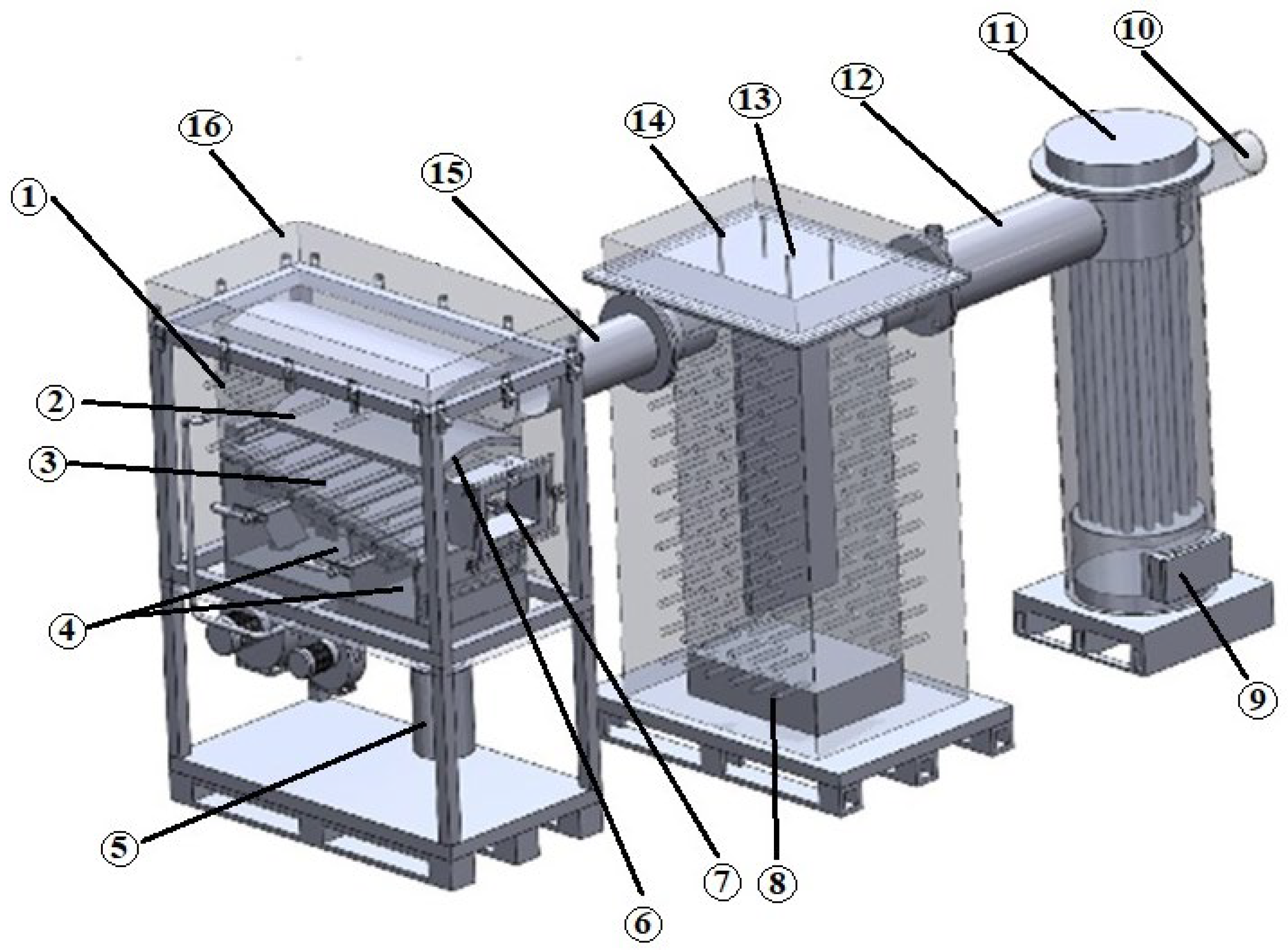
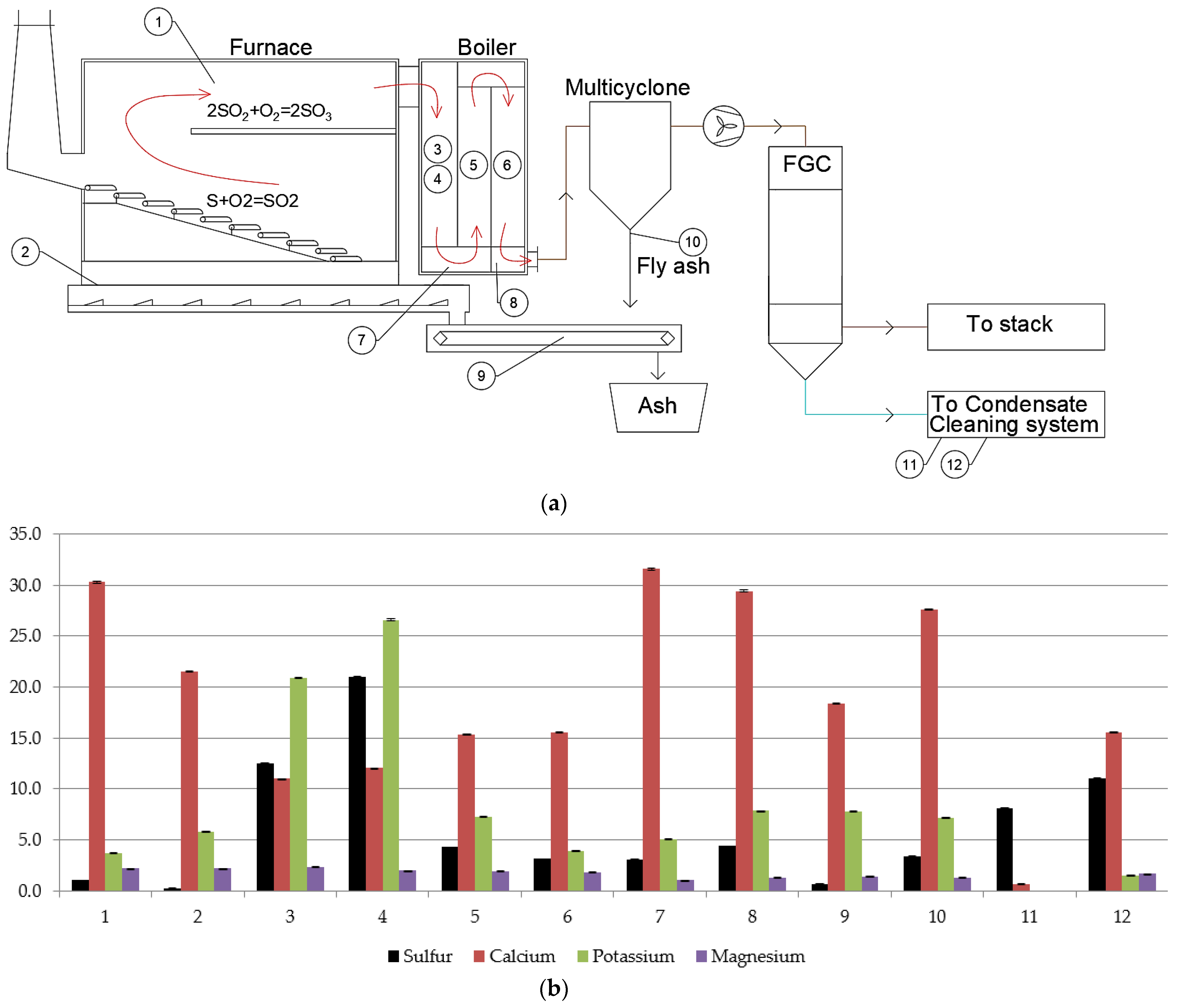
2.1. Description of the Experiments Using Experimental Stands

The sulfur emissions research was executed using two experimental stands, while ash samples were taken from an industrial boiler flue gas pathway. Experimental stand A (Figure 1) was 20 kW capacity, while experimental stand B (Figure 2) was 25 kW capacity. They were both technologically identical to industrial boiler aggregates: the furnace was equipped with a screw fuel feeder, an inclined reciprocating grate with a speed regulation system, fans for primary and secondary air supply for combustion, and a flue gas removal fan, such as in an industrial boiler. The furnace was equipped with an inspection window to monitor the combustion process. These stands were chosen because they are technologically capable of replicating the combustion that takes place in an industrial incinerator; similar proportions of air can be supplied in the same places, the identical combustion temperature, the same number of combustion zones, and similar residence times of emissions in the furnace are achieved. The water temperature to and out of the boiler is in the range of the real hot water network, and the flue gas temperature after the boiler is of the industrial one. Based on that, the formation of the emissions is identical to what it is in industrial-size furnaces and boilers. The main differences between the stands were that stand A had a short final combustion zone, i.e., just after the secondary combustion zone, the shell boiler rapidly cooled the combustion products, and the reactions were stopped. In this case, the composition of the combustion products showed what came out of the secondary combustion zone. In stand B, the path for combustion products is lengthened by including an uncooled section—a 2-stage experimental section. This design allows the combustion products to maintain a high temperature for a duration similar to an actual biomass boiler, specifically around 1 to 2 s. Prolonging the time at high temperatures facilitates chemical processes that closely resemble those occurring in an actual boiler.
The fuel was supplied from the fuel bunker to the combustion chamber and onto the moving grate. In all cases, primary air was supplied below the grate using a primary air fan. In some experiments, the primary air was mixed with recirculated flue gas extracted after the boiler. In these cases, up to 50% of the primary air consisted of recirculated flue gas, with the remaining portion being fresh air. In both stands, secondary air was supplied above the furnace intermediate arc using a separate air fan. The furnaces were adiabatic, without heat exchange surfaces, and the combustion temperature was maintained in the range of 900–1200 °C.
In the first stand, the combustion products after the furnace were supplied to the horizontal shell boiler and then directed to the flue gas outlet using the main flue gas fan. Flue gas measurement points were installed along this pathway. In the second stand, the flue gas from the furnace passed into an experimental section designed to inject various materials; however, the injections of CaO in this study were performed directly to the furnace. Subsequently, the flue gas was directed to a vertical boiler, after which it was discharged into the chimney using the flue gas fan. Measurement points were positioned between the boiler and the flue gas fan. Water temperature regime was maintained at 80–90 °C in both boilers to prevent flue gas condensation.
All emissions measurements were converted to the standard oxygen content in the flue gas, O2 = 6% vol. dry, according to the EU directive 2015/2193 [2]. The flue gas volume was recalculated to standard conditions, i.e., at a temperature of 0 °C (273.15 K) and an atmospheric pressure of 101.325 kPa.
In addition to emission measurements, biomass fuel ashes were studied in the final part of this work, where the sulfur distribution along the flue gas tract was analyzed. These samples were collected from an industrial biomass boiler and examined for their elemental composition using energy-dispersive X-ray spectroscopy (EDS). EDS analysis was employed to characterize the sample’s elemental and chemical composition. The analysis results were presented in chromatograms with assigned peaks of characteristic elements and a table with the calculated percentage composition of the sample.

2.2. Experimental Fuel

The experiments were carried out by separately burning various fuel types with different chemical compositions. For the leading experiments in Section 3, these fuels were sunflower husk pellets and meat bone meal. Woodchips were also compared, as their ash and deposits were taken from the industrial boiler using this fuel for combustion. The specifications of fuel sulfur content, moisture, and lower calorific values are given in Table 1 as dry matter.
The physical and chemical properties of the S content in the fuel and the fuel moisture were determined in accredited laboratories. The chemical composition of sulfur was determined based on EN ISO 16994:2016 [38]. The physical properties of the fuel moisture were determined by EN ISO 18134-2:2024 [39]. The physical properties of the fuel’s lower calorific value were determined by EN ISO 18125-1:2017 [40].

2.3. Description of the Measuring Equipment

The experiments were conducted using electrochemical cells MRU Vario Luxx (MRU Messgerate fur Rauchgase un Umwektschutz GmbH, Neckarsulm, Germany), which was used for continuous emission measurements and loggings of mainly SO2, H2S, CO, CO2, temperature, and O2 content of flue gas. A Fourier transform infrared (FTIR) spectrometer, Gasmet DX4000 (Gasmet Technologies Oy, Vantaa, Finland), was used to measure SO2, SO3, hydrocarbons, and O2. Based on gas diffusion technology, the oxygen content of the sample gas was measured with a 2-electrochemical sensor, while the emissions were measured with a 3-electrode electrochemical sensor. To prevent SOx condensation and measurement errors, a heated hose and probe were used during the tests on the experimental stand.

3. Results

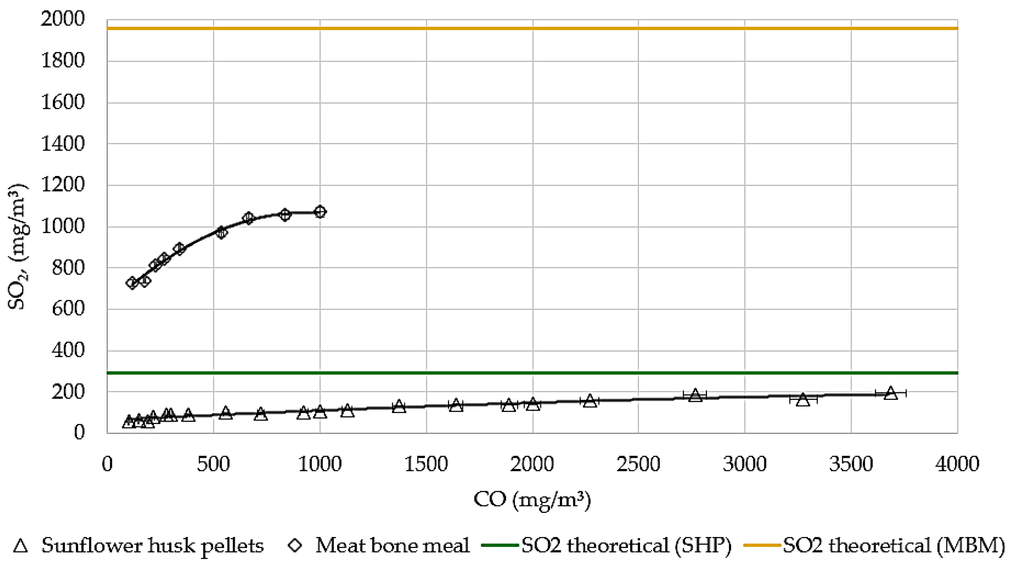
3.1. Theoretical and Experimentally Measured Values

The theoretical amount of SO2 was calculated assuming that all fuel sulfur has converted to SO2. This value is always higher than experimentally measured concentrations. By burning biomass, S = 0.02% (woodchips), S = 0.095% (sunflower husk pellets), and S = 0.63% (meat bone meal). If all fuel sulfur converts to SO2 the following concentrations should occur: 66 mg/m3, 292 mg/m3, and 1960 mg/m3. However, theoretically calculated SO2 differed from experimentally measured SO2. Therefore, the distribution of sulfur in other compounds and flue gas ash deposits was investigated. Theoretical calculations were made for biomass at 55% moisture, O2 = 6% dry volume.

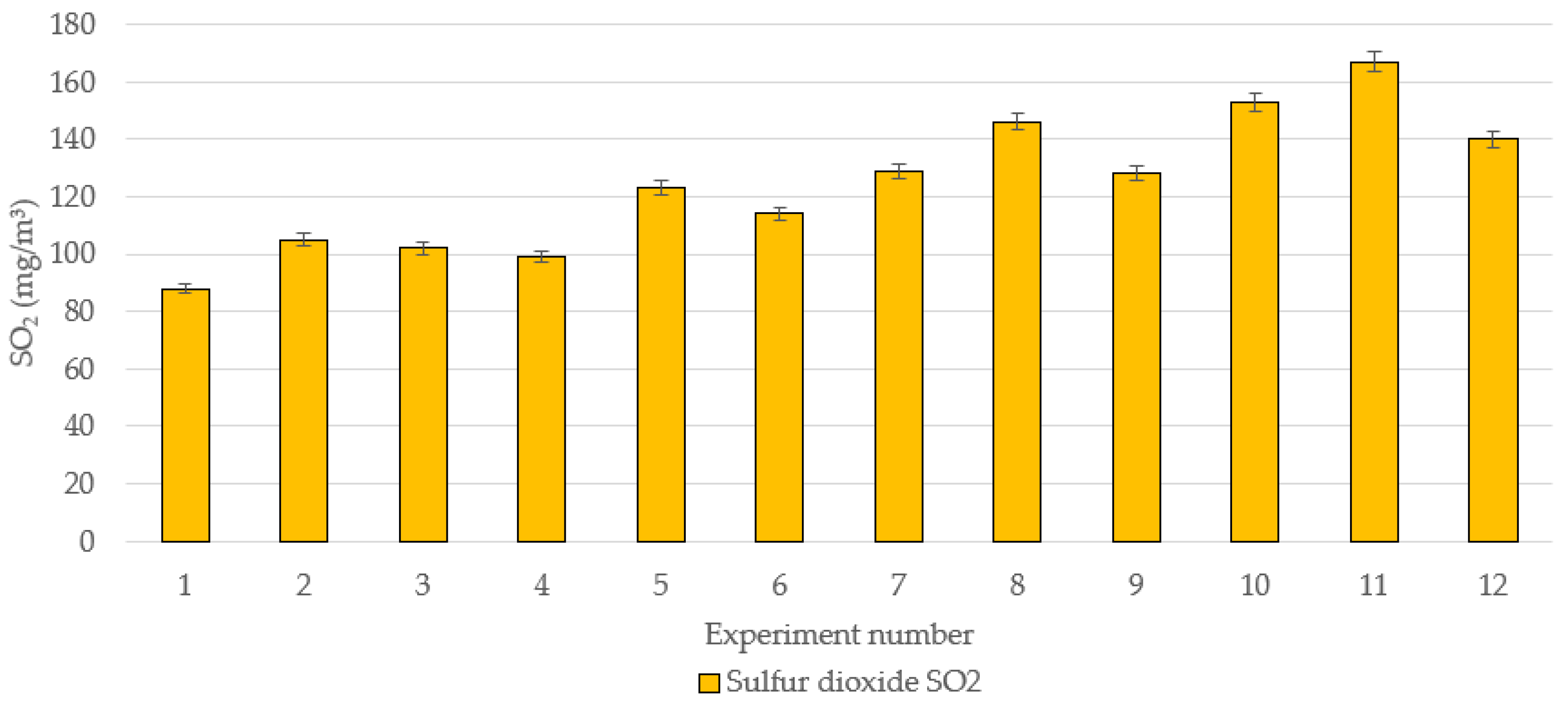
3.2. The Influence of Combustion Completeness on Sulfur Compounds Emissions

The air staging method was also applied during the experiments. During the combustion of sunflower husk pellets and meat bone meal in experimental stands, the influence of CO on SO2, SO3, and H2S emissions was investigated. The CO was increased by adjusting the primary and secondary air flows without flue gas recirculation.
The combustion regimes were divided into several groups, according to the completeness (quality) of combustion and CO concentration in flue gases after boiler: 0–300 mg/m3 (good quality), 300–1000 mg/m3 (lower quality), 1000–2000 mg/m3 (poor quality), and >2000 mg/m3 (worse quality). The combustion regimes were carried out by CO measures up to 4000 mg/m3 by burning sunflower husk pellets. However, during experiments with meat bone meal fuel, reaching CO emissions of >1000 mg/m3 was impossible due to a higher combustion temperature. The CO influence on SO2 is given in Figure 3, SO3 in Figure 4, and H2S in Figure 5.
The effect of CO on sulfur compound emissions was similar during the combustion process of sunflower husk pellets and meat bone meal. As CO levels increased, SO2 exhibited an increasing trend, whereas SO3 showed a decreasing trend. However, the results for H2S suggest a more complex interaction or variability in the conditions affecting its formation than resulting directly from CO.
Within the limits of efficient fuel combustion where CO levels are below 300 mg/m3, the relative increase of SO2 emissions was more prominent when burning sunflower husk pellets. A significant relative increase in SO2 concentrations was observed in this case (from 58 to 88 mg/m3). In contrast, when burning meat bone meal, the percentage increase in SO2 emissions was lower, with concentrations rising from 730 mg/m3 to 840 mg/m3. Similar tendencies were observed at the lower combustion regime in the CO range 300–1000 mg/m3, where SO2 increased to 102 mg/m3 and 1055 mg/m3, respectively. Poor (CO = 1000–2000 mg/m3) and worse (CO > 2000 mg/m3) quality combustion regimes results showed that with the higher CO content, the SO2 starts to grow more during sunflower husk pellet combustion—to 138 mg/m3 and 195 mg/m3, respectively. Sunflower husk pellets show a more pronounced relative increase in SO2 emissions when compared to meat bone meal despite lower absolute concentrations. Similar trends were observed under lower combustion quality, where SO2 emissions increased for both fuel types but remained relatively higher for meat bone meal. Under poor combustion conditions, SO2 emissions increased as CO levels rose. This indicates that suboptimal combustion significantly enhances SO2 production due to insufficient free oxygen to oxidize into SO3, as shown in Equation (3). Furthermore, as carbon monoxide levels increase, it reacts with calcium sulfate to release SO2, as explained in Equation (8). This reaction also accounts for the observed rise in sulfur dioxide emissions. However, neither the sunflower husk pellets nor the meat bone meal achieved the theoretical SO2 values, which are 292 mg/m3 and 1960 mg/m3, respectively. In this experiment, at a sulfur content of 0.1%, the experimental SO2 level was 33% lower, while at 0.6%, the SO2 value was lower by 45%. These findings suggest that as the sulfur content in the fuel increases, a smaller portion of the fuel’s sulfur is converted into SO2 during combustion.
While burning sunflower husk pellets at efficient and lower quality regimes, the SO3 emissions fluctuated around 10 mg/m3, and a significant variation was not observed. However, a greater reduction was observed in poor and worse regimes, with SO3 emissions decreasing to 9 mg/m3 and 6 mg/m3, respectively. This can be explained by the insufficient availability of free oxygen to oxidize SO2 to SO3 [7]. Additionally, the presence of CO creates a reducing environment, which promotes the conversion of SO3 back to SO2.
The deviations in H2S emissions for both fuels were different. In the case of sunflower husk pellets, emissions decreased from 34 mg/m3 to 22 mg/m3 under the regime where CO concentrations were maintained below 300 mg/m3. However, under all subsequent regimes, H2S levels increased, reaching up to 62 mg/m3. In the case of meat bone meal, H2S emissions consistently decreased. During the first regime, the concentrations dropped from 114 mg/m3 to 72 mg/m3, and in the second regime—to 22 mg/m3. This can be attributed to the different fuel composition, as meat bone meal contains high calcium content—5.7% calcium in its dry composition [41]. During the initial combustion reactions, calcium readily binds with sulfur. However, as CO levels increase, a reaction Equation (9) occurs where calcium reacts with CO, releasing SO2 emissions [30].

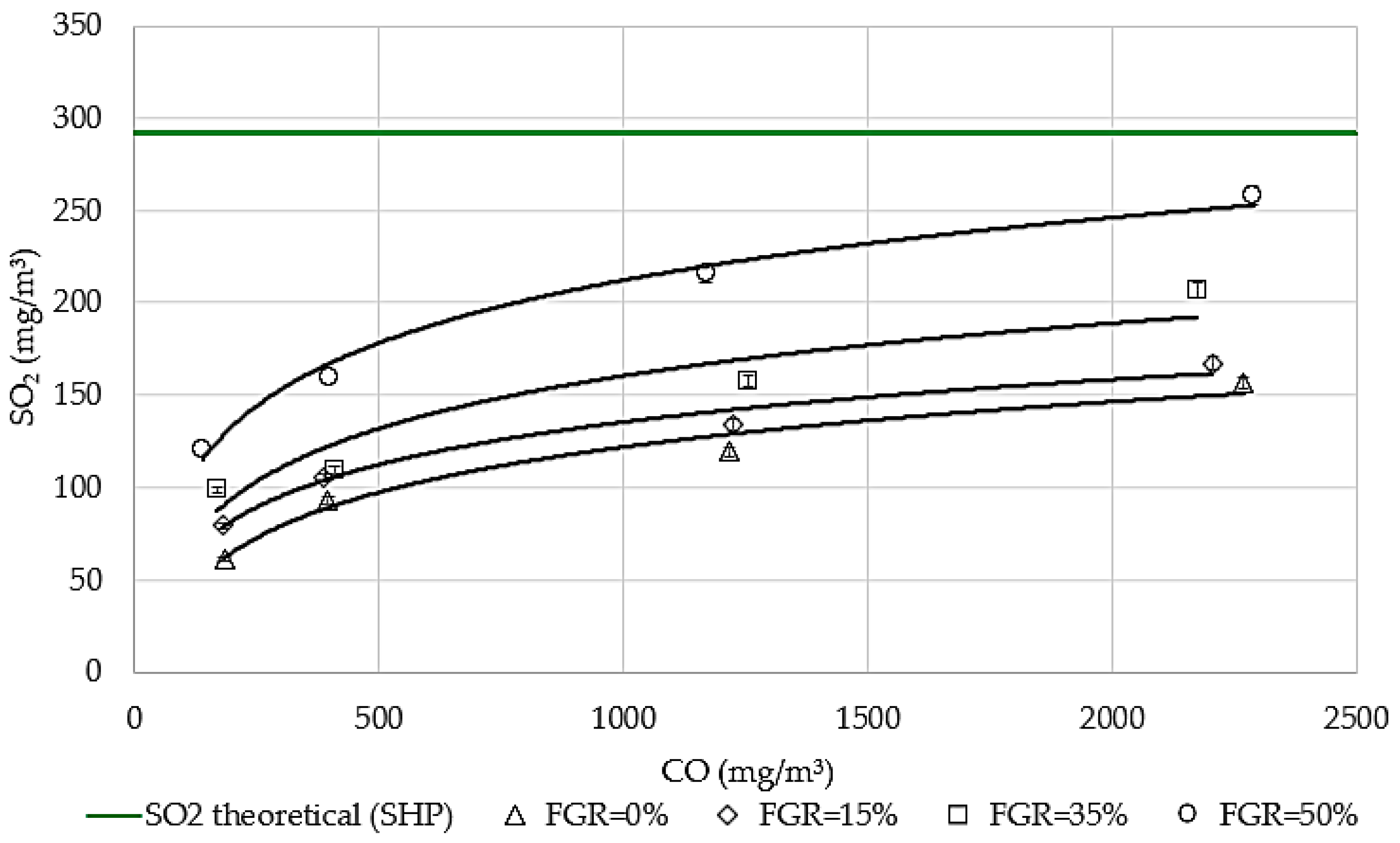
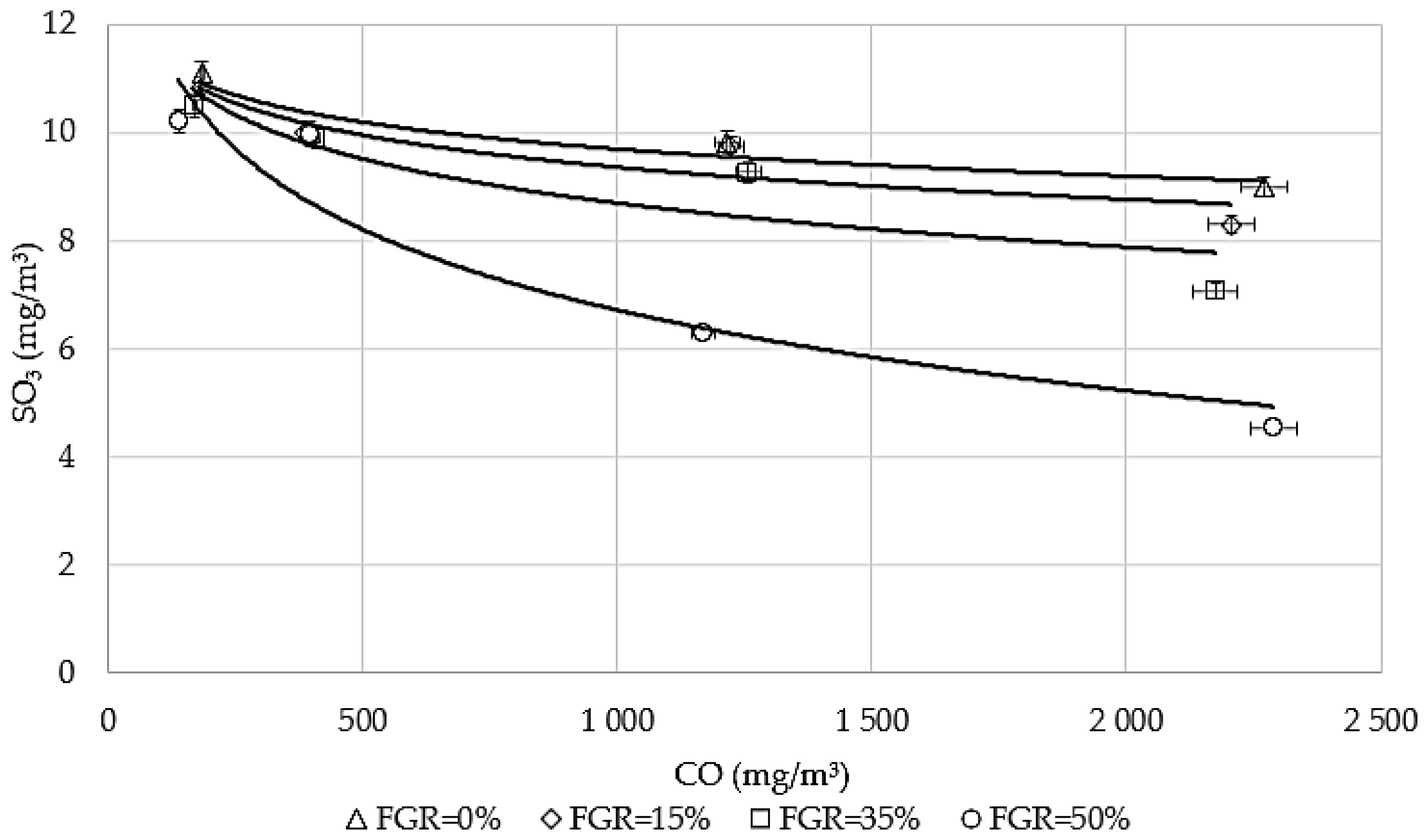
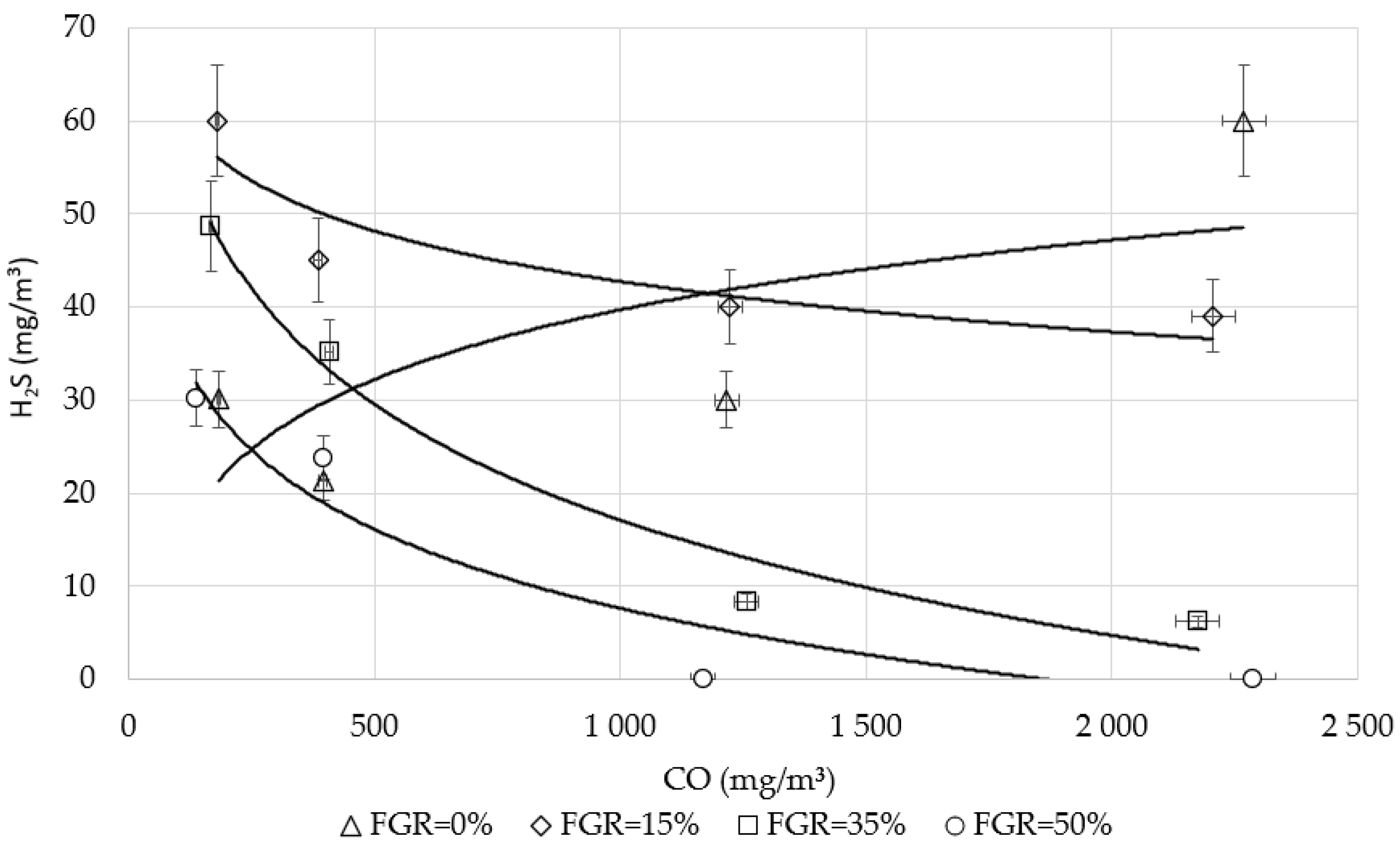
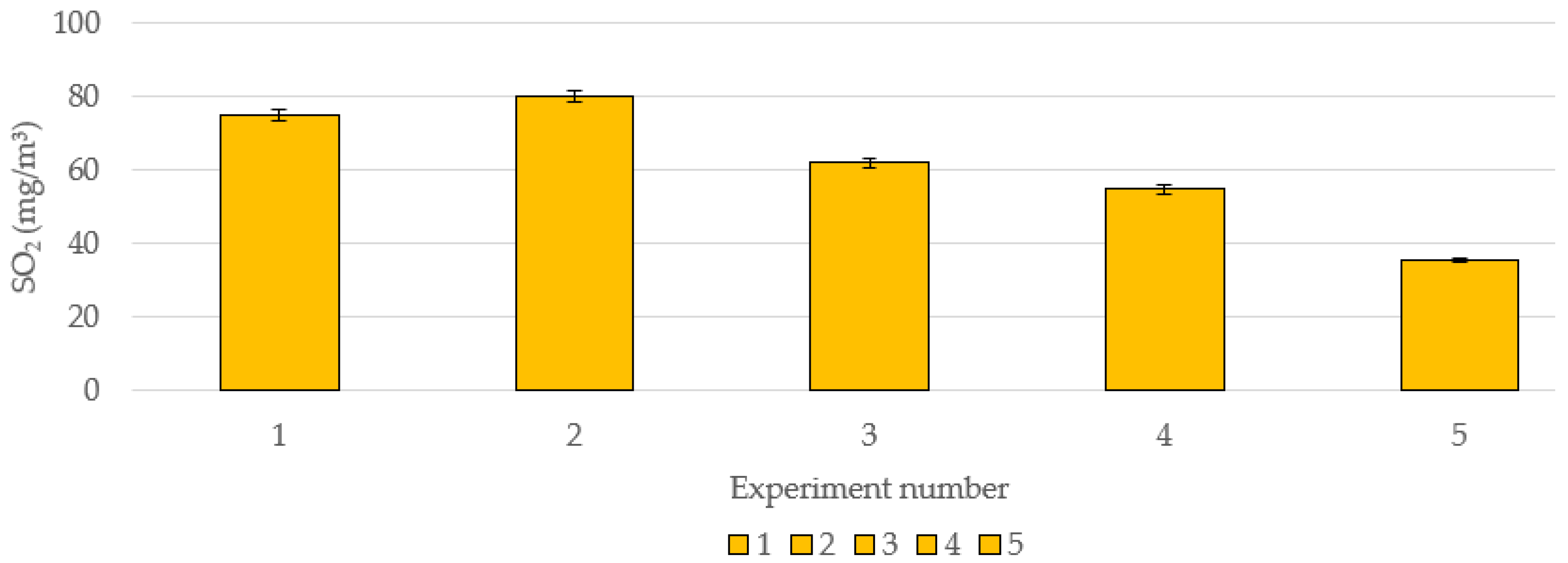
3.3. The Influence of CO on Sulfur Emissions Under Flue Gas Recirculation

Biomass combustion, particularly in industrial processes, is commonly carried out by introducing flue gas recirculation back to the combustion chamber, supplying it under the grates or above the fuel layer, or mixing it with primary or secondary air by combining FGR and fresh air. FGR is a well-known measure for reducing NOx; however, there is limited research on how FGR influences sulfur emissions. This section analyzed the relation between SOx and CO emissions when burning sunflower husk pellets, particularly when recirculated flue gas constitutes a portion of the primary air supply. The experiments were organized into groups, with 0%, 15%, 35%, or 50% of FGR making up the airflow supplied with primary air. Recirculated flue gas was mixed with the fresh air at the inlet of the primary air fan by control valves. The idea was to reduce the oxygen in primary air to slow down the combustion reactions and reduce local combustion temperature as in an actual industrial boiler. The amount of FGR was calculated according to the oxygen concentration in a mix with air: FGR = 0% meant that O2 = 21% was present in the primary air; FGR = 15%—O2 = 18.7%; FGR = 35%—O2 = 15.7%; and FGR = 50%—O2 = 13.5%. The research was conducted by analyzing SO2, SO3, and H2S emissions.
The results regarding the influence of CO on SO2 emissions at various FGR ratios are illustrated in Figure 6. In all cases, SO2 emissions increased with higher CO concentrations, which was consistent with findings from other studies. Notably, without FGR, the relative increase in SO2 emissions was the most significant, rising 2.5 times from 63 mg/m3 to 152 mg/m3. When FGR was introduced, the relative change in SO2 emissions decreased. With 15% FGR, emissions increased 1.6 times, from 94 mg/m3 to 157 mg/m3. However, as the FGR proportion in the primary air increased, the relative change in emissions rose again—2.1 times under both 35% and 50% FGR. This resulted in SO2 growing from 99 mg/m3 to 207 mg/m3 at 35% FGR and from 125 mg/m3 to 264 mg/m3 at 50% FGR. Overall, absolute SO2 emission levels increased with higher FGR ratios. This phenomenon can be explained by the effects of FGR on the chemical reaction dynamics within the combustion chamber. Since SO2 is generated directly from the sulfur in the fuel, limited oxygen availability hinders its further oxidation to SO3. Additionally, an interaction may occur between CaSO4 and CO, leading to the release of SO2 [30]. It is noted that the theoretical maximum SO2 concentration of 292 mg/m3 was not reached, indicating that the remaining sulfur was converted into SO3, H2S remained in the bottom ash, or formed deposits. The fluctuation in SO2 levels highlights its dependence on combustion conditions, suggesting that the theoretical emission calculations, which assume that all the sulfur in the fuel is converted to SO2, cannot be accepted. Therefore, further analysis was conducted on SO3 and H2S emissions.
Significant changes in SO3 emissions were observed with increasing CO concentrations at the highest FGR ratio, as shown in Figure 7. At this FGR ratio, SO3 emissions decreased from 10.2 mg/m3 to 4.2 mg/m3. In contrast, at lower FGR ratios, the decrease in SO3 emissions was less pronounced. Specifically, without FGR, emissions dropped from 11.1 mg/m3 to 9.0 mg/m3; with 15% FGR, they fell from 10.8 mg/m3 to 8.1 mg/m3; and with 35% FGR, they declined from 10.5 mg/m3 to 7.1 mg/m3. These findings indicated that as CO concentrations in the flue gas increased, the rise in SO2 emissions was accompanied by a decrease in SO3 emissions. Therefore, it can be concluded that with higher CO levels and the presence of FGR, the percentage conversion of SO2 to SO3 decreased. These results are consistent with the theory that SO3 concentrations increase under oxidative conditions when combustion is carried out with a higher excess air factor. Higher CO and FGR ratios create reducing conditions that are not favorable for SO3 formation.
A different situation was observed with the H2S emissions while changing the FGR ratio in Figure 8. It was observed that without introducing flue gas recirculation, H2S emissions increased with rising CO levels, from 30 to 60 mg/m3. It could be stated, as by Cai et al. [42], that in the reductive zone, some SO2 and other oxidative sulfur species were reduced to H2S. With a more substantial reductive atmosphere, the CO concentration was higher; thus, more H2S was produced. When FGR was applied, the situation changed significantly—H2S emissions started to decrease as CO levels increased. Specifically, with 15% FGR, H2S decreased from 60 to 39 mg/m3; with 35% FGR, it decreased from 49 to 6 mg/m3; and with 50% FGR, it dropped from 30 to 0 mg/m3. It could be explained as FGR reduces the local combustion temperature, which slowed down the kinetics of H2S formation, and a more significant part of sulfur was oxidized to SO2 as the conditions for H2S formation became less favorable. Additionally, at lower temperatures, the formation of H2S through the reaction of sulfur with hydrogen became less intense, as also stated by Li et al. [27].

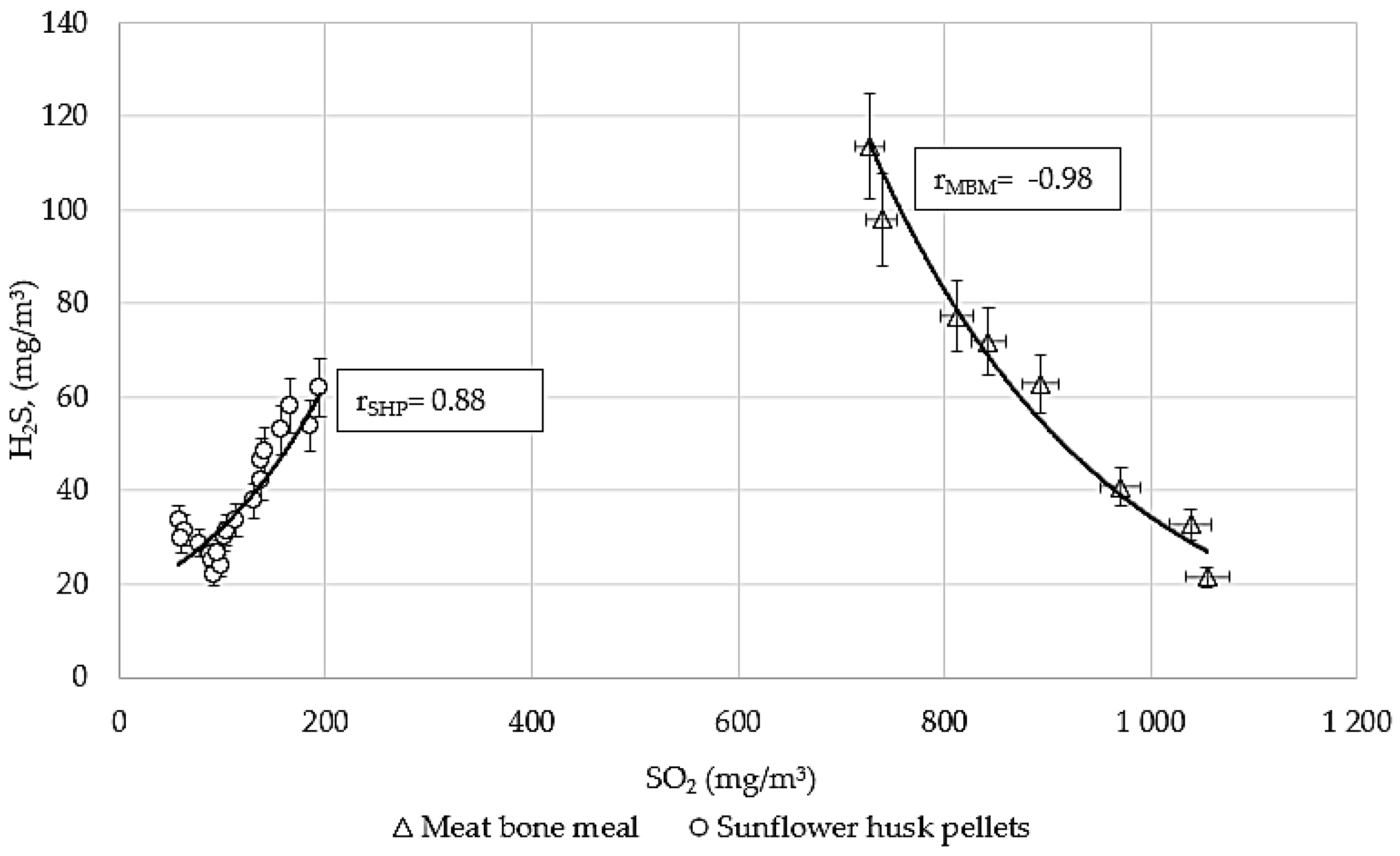
3.4. The Correlation Between SO2 and H2S

The correlation between SO2 and H2S is a topic of interest in sulfur emissions from biomass combustion processes. This correlation provides insights into whether the formation of H2S emissions significantly contributed to the discrepancy between theoretical and experimentally measured SO2 emission values.
The trend in Figure 9 shows the analysis of the correlation between SO2 and H2S. The emissions of H2S increased from 25 mg/m3 to 62 mg/m3 in the case of sunflower husk pellets, while the SO2 increased from 64 to 195 mg/m3. Conversely, a different effect on meat bone meal was observed, where the H2S tended to decrease from 114 mg/m3 to 22 mg/m3 while SO2 increased from 727 mg/m3 to 1055 mg/m3.
Without mixing FGR with the primary air, H2S emissions increased for low-sulfur fuels, even as SO2 emissions increased. In contrast, for high-sulfur fuels, H2S emissions showed a decreasing trend, even as SO2 emissions increased. This suggests that sulfur transformation dynamics vary significantly depending on the sulfur content of the fuel and the absence of recirculation mechanisms. H2S is typically formed under reducing conditions, whereas SO2 is formed under oxidizing conditions. However, meat bone meal contained a high amount of calcium, which readily reacted with sulfur at the initial stages of combustion to form CaSO4. As the reducing environment intensified, a reaction occurred between CO and calcium sulfate, releasing SO2 emissions into the combustion products but not H2S. Calcium in the fuel was vital in sulfur immobilization and in the transformation of sulfur compounds under varying combustion conditions [30,43].

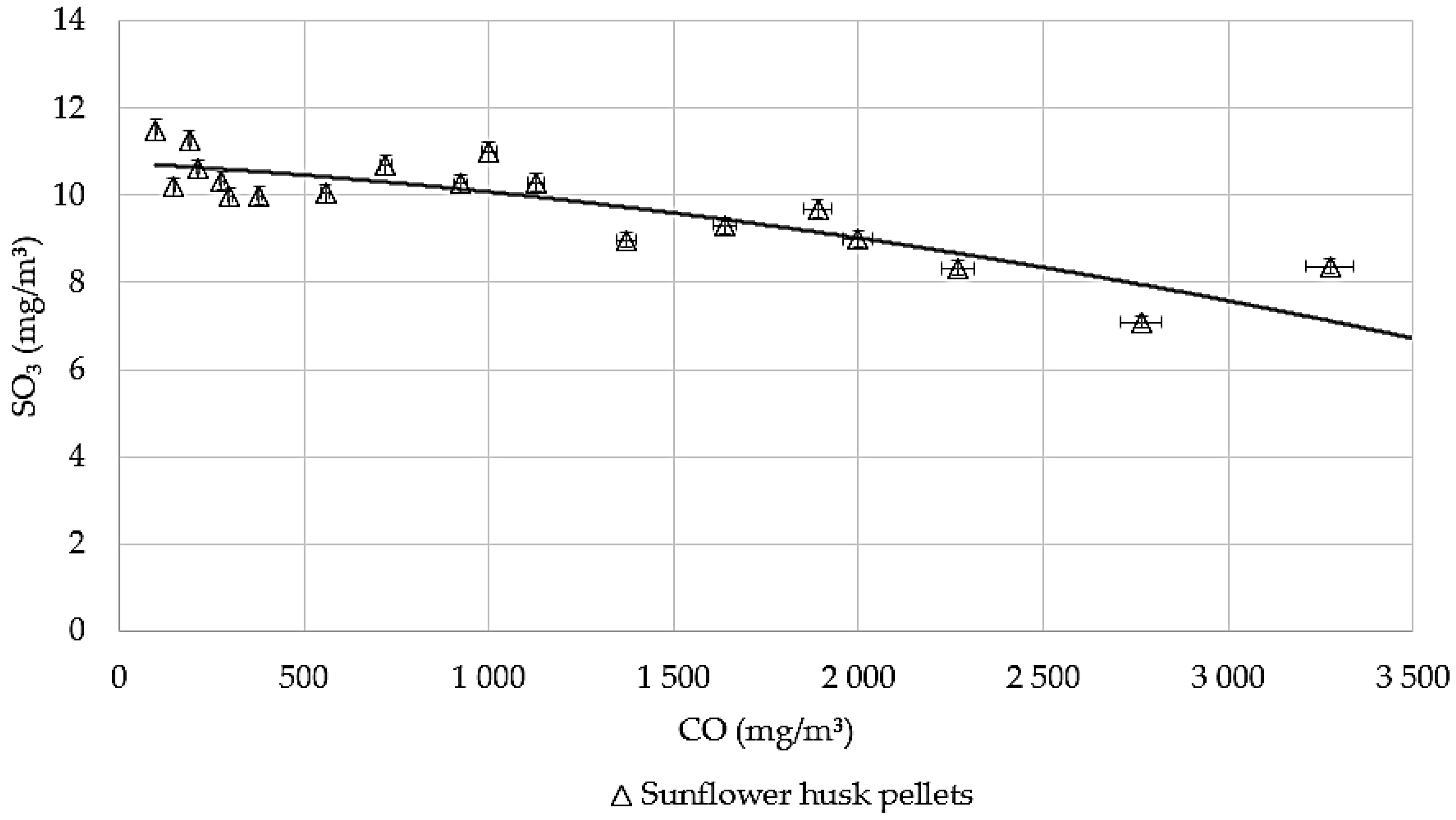
3.5. The Correlation Between SO2 and SO3

Several factors influence the typical formation of SO3, such as fuel composition, combustion temperature, and the presence of catalyst material in the furnace. SO3 is formed during the oxidation of SO2; therefore, the driving forces of SO3 formation include oxygen for combustion and temperature. According to Fleig et al. [44], the maximum SO3 concentrations are at 900–1000 °C combustion temperature. While the typical conversion rate from SO2 to SO3 is 1% to 5% [4].
During this study, an inverse relationship between SO2 and SO3 was observed, where a decrease in SO2 corresponded to an increase in SO3 and vice versa while burning sunflower husk pellets. This trend is shown in Figure 10. These analyses correlated oxygen levels in flue gas with sulfur oxides, suggesting that oxidation was the primary mechanism driving the conversion of SO2 to SO3, as the combustion temperature was stable in the range of 900–1000 °C throughout the experiment. These findings coincided with established chemical principles and underscored the importance of controlling oxygen levels to manage SOx emissions effectively. Sulfur dioxide oxidation is according to Equations (3) and (6). Other authors support our paper, finding that the conversion of SO2 to SO3 increases as the oxygen content rises. For instance, Sporl et al. [6] show that the maximum SO2 values occur under stoichiometric conditions of 0.85 to 1. However, these values are halved when the excess air coefficient reaches 1.7, which corresponds to an O2 concentration of 9%. Under these conditions, the SO2 to SO3 ratio is approximately 3 to 5%. Similar results were achieved with increasing the O2 concentration in flue gas from 6% to 9%, reducing SO2 concentrations on average from 75 mg/m3 to 30 mg/m3 while SO3 emissions from 10 mg/m3 to 17 mg/m3 [31].
The influence of O2 on SO2 and SO3 emissions was observed during the combustion of the same sunflower husk pellets but using experimental stands A and B. Both sets of results confirmed the theory that as the amount of oxygen in the combustion process was increased, SO2 oxidized to SO3 up to 5%. While using experimental stand A (Figure 11), it was observed that the maximum value of SO2 = 130 mg/m3 and the minimum value of SO3 = 9 mg/m3 were reached at minimum O2 = 5.3%. At maximum O2 = 7.8%, SO2 decreased to 68 mg/m3, as SO3 increased to 13 mg/m3. Theoretically, at these conditions, if all 5% of S from SO2 was transformed to SO3, the emission values would be SO2 = 292 mg/m3 and SO3 = 15 mg/m3. It can be concluded that nearly 5% of SO2 was converted to SO3. However, the theoretical proportion of SO2 emissions was more than twice the value obtained in practice.
Similar trends were observed using experimental stand B at an O2 concentration of 7.1%, where SO2 reached a maximum value of 143 mg/m3, while SO3 was at a minimum of 8.5 mg/m3. As the oxygen content in the flue gas increased, the SO2 concentration decreased to 41 mg/m3 at O2 = 9.8%, whereas SO3 increased to 15.5 mg/m3. Theoretically, at these conditions, if all 5% of SO2 was transformed to SO3, the emission values would be as follows: SO2 = 292 mg/m3 and 17 mg/m3. The results are identical to the previous results—nearly 5% of SO2 was converted to SO3. However, the theoretical proportion of SO2 emissions was much higher than the value obtained in practice. Also, Figure 11 shows that the SO2 oxidation to SO3 was similar in both experimental stands with identical biomass fuel and similar combustion regimes.

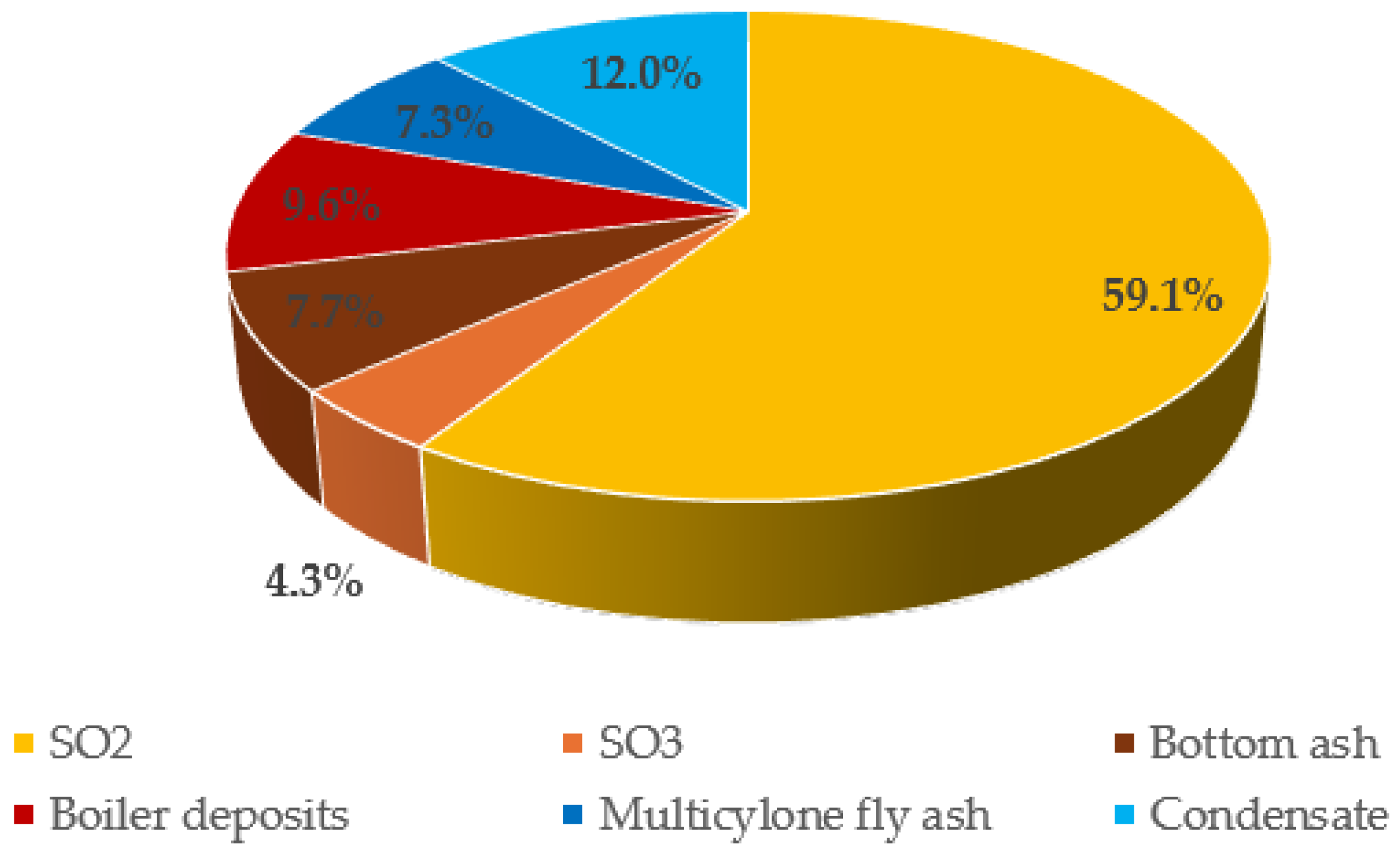
3.6. Sulfur Content in Flue Ash Deposits

Since the theoretical SO2 values are not achieved experimentally, the sulfur content in flue ash deposits was analyzed. The amount of residual sulfur in ash and its deposits along the flue gas pathways depends on several factors, including the type of biomass, the combustion conditions, and the efficiency of the flue gas treatment system. The fuel type plays a significant role in deposit formation. For instance, biomass fuels can be categorized into three groups: straws and grasses, agricultural byproducts, and woods with waste fuels. Each of the mentioned products has different ash deposition tendencies [45]. The sulfur content in fuels also varies, affecting the formation of SO2 and deposits [46]. Additionally, the sulfur deposit formation can be altered by combustion conditions. Oxy-fuel combustion, compared to air-fuel combustion, results in increased SO3 concentrations due to higher SO2 levels [44,47]. In addition, the stoichiometry, residence time, and flue-gas cooling rate are also critical factors in SO3 formation [46].
During combustion, the sulfur was released as a gaseous sulfur compound or retained in bottom ash as solid-phase sulfates. The gaseous portion of the sulfur compounds is formed during the oxidation of sulfur, as described in previous sections. When water vapor (which can come from the moisture in the fuel or the air) is present, SO3 can react with it to form sulfuric acid (H2SO4), which may condense on cooler surfaces. The condensation temperature of sulfuric acid is influenced by the excess air, fuel moisture, and the oxidation levels of SO2 to SO3. Additionally, sulfur oxides can react with alkaline metals to form sulfates, such as K2SO4 or CaSO4, in the fly ash. As these deposits, which include alkaline metals, accumulate, they can lead to corrosion of the heating surfaces [43]. Sulfates also contribute to the formation of particles and deposits on heating or duct surfaces.
During the experiments, the ash samples were collected along the flue gas pathway using wood chips for combustion. The flue gas pathway consisted of the furnace, three flue gas passes of an industrial 8 MW hot water boiler, a multicyclone, a flue gas condenser, and ducts between the equipment (Figure 12a). Sulfur samples of the flue gas condenser were taken from the collected condensate sludge in the condensate treatment system. All locations that the samples were taken from are listed in Figure 12a and could be categorized into three groups: bottom ash (1, 2, 9), fly ash deposits (3–8, 10), and flue gas condensing economizer (FGC) condensate sludge (11, 12). In addition to sulfur analysis, samples were also analyzed for calcium, potassium, and magnesium to determine the potential formation of sulfate compounds. In Figure 12b, the amounts are given in percentage of all the samples in specified locations.
The sulfur content in bottom ash was relatively low compared to the other cases—1.1%. A similar amount of sulfur was above the grates and in the ash transporters (below 1%). Since the sulfur content in the bottom ash was low, but S was observed in higher amounts in other samples, it can be stated that sulfur predominantly reacted in the gaseous phase and exits the combustion chamber as pollutants such as SO2, SO3, or H2S. Alternatively, sulfur reacted with elements like Ca, K, and Mg to form sulfates, combined with solid particles, and traveled out of the furnace as fly ash.
Conversely, fly ash tends to settle along the flue gas pathway. A significant part of the sulfur deposits on the first surfaces are relatively colder than the combustion chamber, and the flue gas temperature is highest (~1000 °C). The sulfur deposits were around 20% in the I boiler pass, as the sulfates were near the melting point. Therefore, they could stick to the colder surfaces, as in the II and III boiler passes, which decreases to S = 4.3% and S = 3.1%. Subsequently, the sulfur content in the fly ash at other sampling places was similar: reverse chamber from I to II boiler pass—3.1%, reverse chamber from II to III pass—4.4%, and multicyclone—3.8%.
Higher amounts of sulfur compared to bottom ash but lower than those found in the I boiler pass were observed in the sludge of the flue gas condenser. The highest sulfur concentration was detected within the sludge rather than on the settled deposits on the equipment walls. The maximum sulfur content in the sludge reached 11% in solid particles. Higher sulfur content in the FGC condensate sludge can be explained by the fact that soluble compounds of K, Na, and Mg were washed away with the condensate, while sulfur formed insoluble salts [48].
Comparing with other authors who have conducted similar ash studies, we observe that Davidsson et al. [43] in their studies used a CFB-type boiler burning wood chips and wood pellets of S < 0.01% in dry mass. The sulfur in ash deposits was ~0.2% in bottom ash, ~0.9% in cyclone fly ash, and ~4% in filter fly ash. Gollmer et al. [49] analyzed the ash composition of particulate matter and ash while burning pine woodchips with S = 0.2%. However, not pure sulfur, but sulfate SO42− was analyzed as it reached 41.7% and 30.1% of particulate matter in the duct after the boiler and ESP, respectively. The different situation was analyzing the ash, as SO42− = 1.5% in both the ash removal and ESP cases were conducted.

3.7. Effect of CaO Introduction on SO2 Emissions

A study was conducted to evaluate the effect of calcium oxide (CaO) on SO2. This was performed by either mixing the fuel with CaO or spraying it into different combustion zones. For the experiments, sunflower pellets were used as fuel. Figure 13 presents a side view of the Stand B furnace, with red circles highlighting the locations where the spraying occurred in each case.
The lime-fuel mixing was conducted in several steps, testing different CaO additives: without any CaO, with a 0.5% CaO additive, and with a 1% CaO additive based on the weight of the fuel. These CaO additions were evaluated under varying conditions of FGR at levels of 0%, 15%, 30%, and 50% in the primary air. Figure 14 illustrates the results, which indicate that SO2 emissions were not significantly affected by the addition of CaO to the fuel. Regardless of the amount of CaO added, the SO2 emissions remained relatively stable, fluctuating within a range of 10% across different FGR levels. Specifically, when no FGR was introduced, the SO2 emissions varied between 90 and 105 mg/m3. However, emissions tended to increase with higher FGR levels, and at a 50% FGR ratio, SO2 emissions ranged from 140 to 150 mg/m3. CaO is recognized as an effective method for reducing SO2 emissions when injected into the gas stream [17,50]. However, it appears that CaO remains in the bottom ash, and mixing it with the fuel does not have a significant effect on SO2 emissions. Nonetheless, incorporating CaO into the fuel mixture can help raise the melting point of the ash.
In the CaO injection tests, its powder was introduced using compressed air into various locations of the combustion stand B. Specifically, it was injected above the fuel layer through hole no. 1 (fuel drying zone), into the first combustion zone through hole no. 3, into the secondary combustion zone via hole no. 14, and into the combustion area through hole no. 27 before the exit of the furnace (see Figure 13).
The results are illustrated in Figure 15. It is evident that supplying CaO above the fuel layer through hole no. 1 had no significant effect, similar to the outcome observed when lime was mixed directly with the fuel. This is because combustion did not occur in this zone, and SO2 emissions remained unchanged in the 75–80 mg/m3 range. However, spraying lime into the primary combustion zone through hole no. 3 reduced emissions to 62 mg/m3, while injecting through hole no. 27 further decreased emissions to 55 mg/m3. The most effective reduction was achieved when CaO was supplied into the secondary combustion zone through hole no. 14, where emissions dropped to 36 mg/m3. These findings suggest that CaO reacts with SO2 in the gaseous phase, leading to substantial reductions in emissions within the combustion zone. When CaO was introduced above the fuel layer in the drying zone, the CaO settled into the fuel and could not react with SO2 in the gaseous phase, similar to the previous experiments where CaO was mixed with fuel.
These reduction results can be compared to other systems: Córdoba et al. [17] gave a review of different reduction options. In the case of sorbents, such as CaCO3 or CaCO3∙MgCO3 injection in the furnace, a ~50% of SO2 removal efficiency can be reached at a sorbent molar ratio of Ca/S = 4–5 and up to 80% if the recirculation is applied. Also, 50–60% SO2 reduction was reached in the case of Ca(OH)2 injection in the flue gas duct, while NaHSO3 could give efficiency of 80%. However, wet reduction systems are more efficient: using the same CaO in a scrubber, as a secondary measure, could reduce up to 90% of SO2, while wet limestone system reduction efficiencies are from 92% to 98%.

4. Discussion

The main finding of this study is that experimentally measured SO2 values are lower than theoretically calculated, and the implementation of incomplete combustion and flue gas recirculation in primary air mixture brought the experimental values closer to the theoretical ones.
To understand the distribution of fuel sulfur during combustion, a sulfur balance calculation was performed for an 8 MW biomass boiler, the same as when the ash deposit samples were taken. Burned fuel had 55% moisture content, 1.3% ash content, and a sulfur content of 0.03% in dry mass. At full load operating continuously, the fuel consumption was 4430 kg/h, with a flue gas volume of 17,200 m3/h (at standard conditions), and the ash formation was 25.9 kg/h. Theoretically, the fuel had a yield of 0.8 kg/h of sulfur, released into the emissions and in the bottom and fly ash. Figure 16 illustrates the percentage distribution of sulfur along the flue gas pathway.
The measured sulfur emissions were SO2 = 55 mg/m3 ± 2.75 mg/m3 (59.0%) and SO3 = 5 mg/m3 ± 0.25 mg/m3 (4.3%). The fuel-S converted into emissions was calculated to be 0.51 kg/h ± 0.0255 kg/h or 63.3%. According to the data from the equipment manufacturer, 20% of the ash left the furnace as fly ash and 80% remained in the bottom ash. Based on these calculations, the particulate matter exiting the grate into the boiler was 300 mg/m3 ± 15 mg/m3. After the boiler, it was 250 mg/m3 ± 12.5 mg/m3; after the multicyclone, it was 150 mg/m3 ± 7.5 mg/m3; and after the economizer, it was 80 mg/m3 ± 4 mg/m3.
According to the sulfur content in deposit measurements at different points in the flue gas path of the boiler, as indicated in Figure 12, it is calculated that the sulfur in the bottom ash was 0.06 kg/h ± 0.003 kg/h or 7.7%, in the boiler 0.07 kg/h ± 0.0035 kg/h or 9.6%, in the multicyclone 0.08 kg/h ± 0.004 kg/h or 7.3%, and in the economizer and its condensate 0.06 kg/h ± 0.003 kg/h or 12.0%. In total, the sulfur remaining in the bottom and fly ash is 0.28 kg/h ± 0.014 kg/h or 36.6%.
When summing up the sulfur in the emissions and ashes, the total amount was 0.8 kg/h ± 0.04 kg/h, and it was equal to theoretical sulfur balance values. It can be concluded that the decrease in SO2 emissions was attributable not only to the conversion of one type of emission into another but also to the fact that a substantial portion of the sulfur contained in the fuel leaves the process in the form of deposits and ash.

5. Conclusions

Depending on the combustion conditions, approximately 20–90% of the sulfur in the fuel was converted to SO2. The remaining sulfur existed in various forms, including other sulfur compounds, solid particles within the volatile ash, and surface deposits.
In cases of complete combustion, the SO2 emissions for sunflower pellets reached 20% of the theoretical value, while for meat bone meal, the emissions were 35%.
Incomplete combustion of sunflower husk pellets achieved 67% of the theoretical SO2 yield, while the yield for meat bone meal was 55%. The SO2 yield increased to 90% when sunflower husk pellets were burned with maximum flue gas recirculation included in the primary air supply.
The relationship between SO2 and sulfur trioxide (SO3) concentrations was inversely proportional. This means that as SO2 emissions increased, SO3 emissions decreased. Research indicated that under oxidizing conditions with a carbon monoxide concentration of 0 mg/m3, approximately 5% of sulfur was converted to SO3. When combustion was carried out at maximum SO2 levels without flue gas recirculation, the conversion rate of sulfur to SO3 was about 2%. However, when flue gas recirculation was implemented, this conversion rate decreased to 1.5%.
The relationship between H2S and SO2 was complex: burning low-sulfur fuel correlated positively with increased H2S levels alongside rising carbon monoxide, while high-sulfur fuel showed a negative correlation. Additionally, the use of flue gas recirculation generally reduced H2S concentrations.
The highest sulfur content, measuring 20%, was found in deposits on the first pass of the boiler, while the lowest sulfur content was 0.3% in the ash under the grate.
The conclusions presented in this article are beneficial for the operation of industrial boilers, especially concerning the trends in sulfur formation from fuels that lead to the formation of SO2, SO3, or H2S. This is particularly relevant when implementing flue gas recirculation in industrial settings. By understanding the emissions trends associated with sulfur, it becomes possible to control combustion processes to achieve permissible SO2 levels while preventing the excessive formation of SO3 emissions, which can be hazardous due to their tendency to condense. Furthermore, by recognizing the patterns of sulfur ash deposition, the boiler system design can be optimized to avoid failures at vulnerable points. This might involve selecting materials with higher corrosion coefficients in the design stage or using metals that are more resistant to sulfur deposits and condensation.

Author Contributions

Methodology, G.J. and K.B.; Investigation, G.J. and K.B.; Writing – original draft, G.J.; Writing – review & editing, K.B. and J.Š.; Supervision, K.B. All authors have read and agreed to the published version of the manuscript.

Funding

This research received no external funding.

Data Availability Statement

The original contributions presented in this study are included in the article. Further inquiries can be directed to the corresponding author(s).

Conflicts of Interest

The authors declare no conflict of interest.

References

  1. Kar, T.; Keles, S. Environmental impacts of biomass combustion for heating and electricity generation. J. Eng. Res. Appl. Sci. 2016, 5, 458–465. [Google Scholar]
  2. Directive (EU) 2015/2193 of the European Parliament and of the Council. Available online: https://eur-lex.europa.eu/legal-content/EN/TXT/?uri=CELEX%3A32015L2193 (accessed on 2 December 2024).
  3. Directive 2010/75/EU of the European Parliament and of the Council of 24 November 2010 on Industrial Emissions (Integrated Pollution Prevention and Control). Available online: https://eur-lex.europa.eu/legal-content/LT/TXT/?uri=CELEX:32010L0075 (accessed on 28 February 2025).
  4. Coykendall, L.H. Formation and Control of Sulfur Oxides in Boilers. J. Air Pollut. Control Assoc. 1962, 12, 567–591. [Google Scholar] [CrossRef]
  5. Jaworowski, R.J.; Mack, S.S. Evaluation of Methods for Measurement of S03/H2S04 in Flue Gas. J. Air Pollut. Control Assoc. 1979, 29, 43–46. [Google Scholar] [CrossRef]
  6. Spörl, R.; Maier, J.; Scheffknecht, G. Sulfur Oxide Emissions from Dust-fired Oxy-fuel Combustion of Coal. Energy Procedia 2013, 37, 1435–1447. [Google Scholar] [CrossRef]
  7. Musademba, D.; Simbi, D.; Kuipa, P. Trends in the control of NOx and SOx combustion emissions: Implications to the design of fluidised bed combustion operations. Chin. J. Mech. Eng. 2015, 231, 349–358. [Google Scholar] [CrossRef]
  8. Tang, R.; Liu, Q.; Zhong, W.; Lian, G.; Yu, H. Experimental Study of SO2 Emission and Sulfur Conversion Characteristics of Pressurized Oxy-Fuel Co-combustion of Coal and Biomass. Energy Fuels 2020, 34, 16693–16704. [Google Scholar] [CrossRef]
  9. Roy, Y.; Lefsrud, M.; Orsat, V.; Filion, F.; Bouchard, J.; Nguyen, Q.; Dion, L.M.; Glover, A.; Madadian, E.; Lee, C.P. Biomass combustion for green house carbon dioxide enrichment. Biomass Bioenergy 2014, 66, 186–196. [Google Scholar] [CrossRef]
  10. Løj, L.H. Gas Phase Sulfur, Chlorine and Potassium Chemistry in Biomass Combustion. Ph.D. Thesis, Technical University of Denmark, Kongens Lyngby, Denmark, 2007. [Google Scholar]
  11. Lu, J.; Zhou, Z.; Zhang, H.; Yang, Z. Influenced factors study and evaluation for SO2/SO3 conversion rate in SCR process. Fuel 2019, 245, 528–533. [Google Scholar] [CrossRef]
  12. Carpenella, S.; Cecere, D.; Giacomazzi, E.; Quaranta, I.; Sorrentino, G.; Sabia, P.; Battista Ariemma, G.; Ragucci, R. Large Eddy Simulation of Hydrogen/Air MILD combustion in a cyclonic burner. Appl. Therm. Eng. 2024, 244, 122733. [Google Scholar] [CrossRef]
  13. Fang, L.; Bos, W.J.T. An EDQNM study of the dissipation rate in isotropic non-equilibrium turbulence. J. Turbul. 2023, 24, 217–234. [Google Scholar] [CrossRef]
  14. Sartor, K.; Restivo, Y.; Ngendakumana, P.; Dewallef, P. Prediction of SOx and NOx emissions from a medium size biomass boiler. Biomass Bioenergy 2014, 65, 91–100. [Google Scholar] [CrossRef]
  15. Ciukaj, S.; Pronobis, M. Dew point of the flue gas of boilers co-firing biomass with coal. Chem. Process Eng. 2013, 34, 101–108. [Google Scholar] [CrossRef]
  16. Oviedo, M.D.; Mendoza, J.M.; German, S.S.; Rhenals-Julio, J.D. Effect of biomass addition on SOx, NOx, and CO2 emissions during co-firing of pulverized coal. J. Southwest Jiaotong Univ. 2024, 59, 87–97. [Google Scholar] [CrossRef]
  17. Córdoba, P. Status of Flue Gas Desulfurisation (FGD) systems from coal-fired power plants: Overview of the physic-chemical control processes of wet limestone FGDs. Fuel 2015, 144, 274–286. [Google Scholar] [CrossRef]
  18. Galanopoulos, C.; Yan, J.; Li, H.; Liu, L. Impacts of acidic gas components on combustion of contaminated biomass fuels. Biomass Bioenergy 2018, 111, 263–277. [Google Scholar] [CrossRef]
  19. Srivastava, R.K.; Miller, C.A.; Erickson, C.; Jambhekar, R. Emissions of Sulfur Trioxide from Coal-Fired Power Plants. J. Air Waste Manag. Assoc. 2012, 54, 750–762. [Google Scholar] [CrossRef]
  20. Zewdie, D.F.; Bizualem, Y.D.; Nurie, A.G. A review on removal CO2, SO2, and H2S from fue gases using zeolite based adsorbents. Discov. Appl. Sci. 2024, 6, 331. [Google Scholar] [CrossRef]
  21. Koech, L.; Rutto, H.; Lerotholi, L. Spray drying absorption for desulphurization: A review of recent developments. Clean Technol. Environ. Policy 2021, 23, 1665–1686. [Google Scholar] [CrossRef]
  22. Wang, Y.; Ren, S.; Hou, Y.; Wu, W. Capture of Acidic Gases from Flue Gas by Deep Eutectic Solvents. Processes 2021, 9, 1268. [Google Scholar] [CrossRef]
  23. Sher, F.; Pans, M.A.; Afilaka, D.T.; Sun, C.; Liu, H. Experimental investigation of woody and non-woody biomass combustion in a bubbling fluidised bed combustor focusing on gaseous emissions and temperature profiles. Energy 2017, 141, 2069–2080. [Google Scholar] [CrossRef]
  24. Li, S.; Xu, T.; Sun, P.; Zhou, Q.; Tan, H.; Hui, S. NOx and SOx emissions of a high sulfur self-retention coal during air-staged combustion. Fuel 2008, 87, 723–731. [Google Scholar] [CrossRef]
  25. Khan, W.; Gibbs, B. High temperature desulfurization by fine limestone during staged fluidized-bed combustion. Can. J. Chem. Eng. 2000, 78, 1102–1110. [Google Scholar] [CrossRef]
  26. Shirai, H.; Ikeda, M.; Aramaki, H. Characteristics of hydrogen sulfide formation in pulverized coal combustion. Fuel 2013, 114, 114–119. [Google Scholar] [CrossRef]
  27. Li, J.; Zhang, X.; Yang, W.; Blasiak, W. Effects of Flue Gas Internal Recirculation on NOx and SOx Emissions in a Co-Firing Boiler. Int. J. Clean Coal Energy 2013, 2, 13–21. [Google Scholar] [CrossRef]
  28. Liang, X.; Wang, Q.; Luo, Z.; Eddings, E.; Ring, T.; Li, S.; Lin, J.; Xue, S.; Han, L.; Xie, G. Experimental and numerical investigation on sulfur transformation in pressurized oxy-fuel combustion of pulverized coal. Appl. Energy 2019, 253, 113542. [Google Scholar] [CrossRef]
  29. Li, Y.; Lin, Y.; Zhao, J.; Liu, B.; Wang, T.; Wang, P.; Mao, H. Control of NOx emissions by air staging in small- and medium-scale biomass pellet boilers. Environ. Sci. Pollut. Res. 2019, 26, 9717–9729. [Google Scholar] [CrossRef]
  30. Lupiáñez, C.; Guedea, I.; Bolea, I.; Díez, L.I.; Romeo, L.M. Experimental study of SO2 and NOx emissions in fluidized bed oxy-fuel combustion. Fuel Process. Technol. 2013, 106, 587–594. [Google Scholar] [CrossRef]
  31. Jančauskas, A.; Buinevičius, K. Combination of Primary Measures on Flue Gas Emissions in Grate-Firing Biofuel Boiler. Energies 2021, 14, 793. [Google Scholar] [CrossRef]
  32. Shahzad, K.; Saleem, M.; Ghauri, M.; Akhtar, J.; Ali, N.; Akhtar, N.A. Emissions of NOx, SO2, and CO from co-combustion of wheat straw and coal under fast fluidized bed condition. Combust. Sci. Technol. 2015, 187, 1079–1092. [Google Scholar] [CrossRef]
  33. Ahn, J.; Overacker, D.; Okerlund, R.; Fry, A.; Eddings, E. SO3 Formation During Oxy-Coal Combustion. Int. J. Greenh. Gas Control 2011, 5, 127–135. [Google Scholar] [CrossRef]
  34. Zhang, Z.; Qinda, Z.; Hao, R.; Hongzhou, H.; Yang, F.; Mao, X.; Mao, Y.; Zhao, P. Combustion behavior, emission characteristics of SO2, SO3 and NO, and in situ control of SO2 and NO during the co-combustion of anthracite and dried sawdust sludge. Sci. Total Environ. 2019, 646, 716–726. [Google Scholar] [CrossRef] [PubMed]
  35. Pałaszynska, K.; Juszczak, M. Gaseous emissions during agricultural biomass combustion in a 50 kW moving step grate boiler. Chem. Process Eng. 2018, 39, 197–208. [Google Scholar] [CrossRef]
  36. Jančauskas, A.; Buinevičius, K. Grate-Firing Boilers Grate Movement Impact onto NOx, SO2 Emissions. Mechanika 2020, 26, 503–510. [Google Scholar] [CrossRef]
  37. Zając, G.; Szyszlak-Bargłowicz, J.; Gołębiowski, W.; Szczepanik, M. Chemical Characteristics of Biomass Ashes. Energies 2018, 11, 2885. [Google Scholar] [CrossRef]
  38. EN ISO 16994:2016; Solid Biofuels—Determination of Total Content of Sulfur and Chlorine. ISO: Geneva, Switzerland, 2016. Available online: https://www.iso.org/standard/70097.html (accessed on 1 December 2024).
  39. EN ISO 18134-2:2024; Solid Biofuels–Determination of Moisture Content—Part 2: Simplified Method. ISO: Geneva, Switzerland, 2016. Available online: https://www.iso.org/standard/86024.html (accessed on 1 December 2024).
  40. EN ISO 18125:2017; Solid Biofuels—Determination of Calorific Value. ISO: Geneva, Switzerland, 2017. Available online: https://www.iso.org/standard/61517.html (accessed on 1 December 2024).
  41. Database for the Physico-Chemical Composition of (Treated) Lignocellulosic Biomass, Micro- and Macroalgae, Various Feedstocks for Biogas Production and Biochar. Available online: https://phyllis.nl/Browse/Standard/ECN-Phyllis#meat%20bon%20meal (accessed on 18 December 2024).
  42. Cai, J.; Li, D.; Chen, D.; Li, Z. NOx and H2S formation in the reductive zone of air-staged combustion of pulverized blended coals. Front. Energy 2020, 15, 4–13. [Google Scholar] [CrossRef]
  43. Davidsson, K.O.; Åmand, L.-E.; Leckner, B. Potassium, Chlorine, and Sulfur in Ash, Particles, Deposits, and Corrosion during Wood Combustion in a Circulating Fluidized-Bed Boiler. Energy Fuels 2007, 21, 71–81. [Google Scholar] [CrossRef]
  44. Fleig, D.; Andersson, K.; Normann, F.; Johnsson, F. SO3 formation under oxyfuel combustion conditions. Ind. Eng. Chem. Res. 2011, 50, 8505–8514. [Google Scholar] [CrossRef]
  45. Baxter, L.; Miles, T.R.; Miles, T.R., Jr.; Jenkins, B.M.; Milne, T.; Dayton, D.; Bryers, R.W.; Oden, L.L. The behavior of inorganic material in biomass-fired power boilers: Field and laboratory experiences. Fuel Process. Technol. 1996, 54, 47–78. [Google Scholar] [CrossRef]
  46. Chen, L.; Bhattacharya, S. Sulfur Emission from Victorian Brown Coal Under Pyrolysis, Oxy-Fuel Combustion and Gasification Conditions. Environ. Sci. Technol. 2013, 47, 1729–1734. [Google Scholar] [CrossRef]
  47. Sarbassov, Y.; Duan, L.; Manovic, V.; Anthony, E.J. Sulfur trioxide formation/emissions in coal-fired air- and oxy-fuel combustion processes: A review. Greenh. Gases Sci. Technol. 2018, 8, 402–428. [Google Scholar] [CrossRef]
  48. Castaldi, F.J. Aqueous Behavior of Elements in a Flue Gas Desulfurization Sludge Disposal Site. 1. Waste Water Treatment. Water Encycl. 2005, 1, 848–853. [Google Scholar] [CrossRef]
  49. Gollmer, C.; Siegmund, T.; Weigel, V.; Kaltschmitt, M. Comparative Analysis of Primary and Secondary Emission Mitigation Measures for Small-Scale Wood Chip Combustion. Energies 2024, 17, 4403. [Google Scholar] [CrossRef]
  50. Van Loo, S.; Koppejan, J. The Handbook of Biomass Combustion and Co-Firing; Earthscan: London, UK, 2008; p. 465. [Google Scholar]
Figure 1. Experimental stand A. A 20 kW capacity boiler stand. 1—water outlet, 2—flue gas reverse chamber, 3—fire tubes, 4—hot water boiler, 5—furnace arc, 6—view hatch, 7—ash hatch, 8—flue gas outlet, 9—flue gas inlet to boiler, 10—fuel feeder, 11—motor of conveyor, 12—fuel screw conveyor, 13—secondary air inlet, 14—primary air inlet, 15—biomass furnace, 16—grates, 17—reciprocating grates frame.
Energies 18 01701 g001
Figure 2. Experimental stand B. A 25 kW capacity boiler stand. 1—fuel inlet, 2—secondary air inlet, 3—reciprocating grate, 4—primary air inlet zones, 5—ash outlet, 6—furnace arc, 7—view hatch, 8—tubes for dosing path, 9—view hatch, 10—flue gas after boiler, 11—boiler, 12—flue gas inlet to boiler, 13—2-stage experimental section, 14—tubes for dosing, 15—flue gas after furnace, 16—furnace.
Energies 18 01701 g002
Figure 3. Effect of CO on SO2 emissions for sunflower husk pellets and meat bone meal fuels.
Energies 18 01701 g003
Figure 4. Effect of CO on SO3 emissions for sunflower husk pellets.
Energies 18 01701 g004
Figure 5. Effect of CO on H2S emissions for sunflower husk pellets and meat bone meal fuels.
Energies 18 01701 g005
Figure 6. Influence of CO on SO2 emissions under various rates of FGR.
Energies 18 01701 g006
Figure 7. Influence of CO on SO3 emissions under various rates of FGR.
Energies 18 01701 g007
Figure 8. Influence of CO on H2S emissions under various rates of FGR.
Energies 18 01701 g008
Figure 9. The correlation between SO2 and H2S emissions.
Energies 18 01701 g009
Figure 10. Influence of O2 on the emissions of sulfur oxides.
Energies 18 01701 g010
Figure 11. Relationship between emissions of sulfur oxides.
Energies 18 01701 g011
Figure 12. (a)—Ash sampling scheme. (b)—Sulfur and calcium content of different ash specimens: 1—furnace ash on the walls, 2—bottom ash, 3—ash in flame tube, 4—ash in flame tube, 5—ash in II boiler pass, 6—ash in III boiler pass, 7—Reverse chamber (from I pass to II pass), 8—Reverse chamber (from II pass to III pass), 9—Ash transporter, 10—Multicyclone, 11—Sludge from the flue gas condenser, 12—Sludge from the tank (a solid substance).
Energies 18 01701 g012
Figure 13. Stand B furnace side section view. Red circle points were used for CaO injections.
Energies 18 01701 g013
Figure 14. Experiment of CaO mixing with the fuel. Experiments: 1—CaO = 0%, FGR = 0%; 2—CaO = 0.5%, FGR = 0%; 3—CaO = 1%, FGR = 0%; 4—CaO = 0%, FGR = 15%; 5—CaO = 0.5%, FGR = 15%; 6—CaO = 1%, FGR = 15%; 7—CaO = 0%, FGR = 30%; 8—CaO = 0.5%, FGR = 30%; 9—CaO = 1%, FGR = 30%; 10—CaO = 0%, FGR = 50%; 11—CaO = 0.5%, FGR = 50%; 12—CaO = 1%, FGR = 50%.
Energies 18 01701 g014
Figure 15. SO2 reduction by spraying CaO into combustion zones: 1—without reducing measures; 2—fuel drying zone over fuel layer (hole no. 1); 3—primary combustion zone (hole no. 3); 4—before the exit of the furnace (hole no. 27); 5—secondary combustion zone (hole no. 14).
Energies 18 01701 g015
Figure 16. Percentage distribution of sulfur along the flue gas pathway.
Energies 18 01701 g016
Table 1. Characteristics of the fuel used for experiments.
FuelMoistureSulfur (S)AshLower Calorific Value
%%%kJ/kg
Sunflower husk pellets8.60.0952.915,366
Woodchips450.021.2310,197
Meat bone meal2.90.6322.020,972
Disclaimer/Publisher’s Note: The statements, opinions and data contained in all publications are solely those of the individual author(s) and contributor(s) and not of MDPI and/or the editor(s). MDPI and/or the editor(s) disclaim responsibility for any injury to people or property resulting from any ideas, methods, instructions or products referred to in the content.

