Article

Study on the Influence of Split Blades on the Force Characteristics and Fluid–Structure Coupling Characteristics of Pumps as Turbines

1
School of Energy and Power Engineering, Lanzhou University of Technology, Lanzhou 730050, China
2
Key Laboratory of Fluid Machinery and Systems of Gansu, Lanzhou 730050, China
*
Author to whom correspondence should be addressed.
Energies 2025, 18(7), 1642; https://doi.org/10.3390/en18071642
Submission received: 19 February 2025 / Revised: 11 March 2025 / Accepted: 18 March 2025 / Published: 25 March 2025
(This article belongs to the Section A3: Wind, Wave and Tidal Energy)

Abstract

:
In order to study the influence of split blades on the turbine force characteristics and fluid–structure coupling characteristics of pumps, this paper selected the IS 80-50-315 centrifugal pump, used as a reverse-acting hydraulic turbine, as the research object, optimized the original pump-acting turbine impeller, and adopted different combinations of long and short blades. Based on the SIMPLE algorithm and RNG k–ε turbulence model, a complete three-dimensional unsteady numerical simulation was conducted on the internal flow field of the pump-turbine. The results show that the split blades reduce the radial and axial forces. The deformation patterns of rotor components in the two pump types used as turbine models were similar, with deformation gradually decreasing from the inlet to the outlet of the impeller. The equivalent stress distribution law of the rotor components of the two pump turbine models has also been found to be similar, with the maximum stress occurring at the connection between the blades and the front and rear cover plates and the minimum stress occurring at the outlet area of the impeller and the maximum shaft diameter of the pump shaft. The maximum deformation and stress of the rotor components in the split blade impeller model were smaller than those in the original impeller model.

1. Introduction

As a reversible rotating machine, the pump can be used as a liquid energy recovery turbine to recover residual pressure energy from pressurized industrial wastewater in the chemical industry when the centrifugal pump rotates in reverse. A hydraulic turbine operates by reversing the pump as a turbine, achieving the recovery and utilization of high-pressure liquids; therefore, a centrifugal pump operating in reverse as a turbine is also known as a pump as turbine (PAT). Due to its advantages such as small size, simple structure, low cost, and easy maintenance, the pump as turbine has been widely used in process industries such as petrochemicals [1], coal chemical industry [2], seawater desalination [3], as well as in energy-saving technology fields such as small-scale water conservancy and hydro-power resource development and application [4]. However, the limitations of traditional pump designs have been revealed by recent studies, particularly regarding the structural safety of hydraulic units. High-amplitude, high-frequency pressure fluctuations caused by the rotor–stator interaction (RSI) under off-design conditions are identified as the primary hydraulic excitation source [5]. These pressure fluctuations may induce severe vibrations and fatigue damage to structural components, critically compromising the operational safety of the units. Additionally, pressure pulsations induced by blade rotation are recognized as another potential factor contributing to fatigue damage in structural components, further threatening the safe operation of the equipment [6]. The problems of low recovery efficiency and unstable operation of pump as turbine units during operation have been studied as hot topics by domestic and foreign experts and scholars. The correlation between blade number and both internal flow patterns and radial forces in hydraulic turbines was systematically demonstrated by Li et al. [7]. Through comparative analysis, a 36% reduction in radial force was quantified for six-bladed impellers relative to four-bladed counterparts, with enhanced flow uniformity being attributed to increased blade counts. In a dedicated study on impeller optimization, split blades were incorporated into hydraulic turbine-specific impellers by Wang et al. [8]. The effectiveness of this design modification was verified through flow field analysis, where flow separation was suppressed by 22–28% and velocity distribution uniformity was improved by 17% compared to conventional single-blade configurations. Further investigations by Hu et al. [9] demonstrated that split-blade geometries could elevate PAT efficiency by 8% through optimized vortex control.
Benra et al. [10] analyzed the centrifugal pump impeller rotor deformation caused by hydrodynamic load excitation using unidirectional and bidirectional coupling methods. They provided the distribution law of the overall circumferential deformation of the impeller. Katsutoshi et al. [11] analyzed the stress generated by hydrodynamic loads on the impeller under five different flow rates using a unidirectional sequential fluid–structure coupling method. They found that the stress was highest at a 70% flow rate, and the maximum position was at the blade’s root. Benra et al. [12] compared two coupling solution methods, unidirectional and bidirectional coupling, and solved for a single-blade sewage pump. They found that bidirectional coupling can predict a broader range of impeller trajectory curves, but the solution time is 3–4 times that of unidirectional coupling. The radial force distribution of the heart pump rotor was studied by Adkins et al. [13] and Barrio et al. [14] through theoretical analysis and numerical calculations. Yang et al. [15] analyzed the influence of different blade numbers on the operational stability of turbine units. They found through simulation that appropriately increasing the blade number of the impeller can significantly reduce the pressure amplitude inside the centrifugal pump as a hydraulic turbine, thereby enhancing the stability of turbine operations.
Blade diversion technology is a commonly used technique in the design and application of turbomachinery [16,17,18]. Daniel et al. [19] studied the effect of split blades on the performance of centrifugal pumps as hydraulic turbines at different flow rates and speeds. By comparing the six-blade design without split blades and the four-blade design with split blades, it was found that using split blades resulted in a more uniform pressure distribution and was more suitable for turbine operation than not using split blades. Recent advancements by Yunguang Ji et al. [20] further emphasized the need for multi-objective optimization in PAT blade design to balance efficiency and structural integrity across operational scenarios. The elastic dynamics problem between fluid film lubrication and bearings in the journal was studied by Liu et al. [21], who considered the effect of fluid–structure coupling based on the Navier–Stokes theory. CFD-related software was used to establish models of fluids and structures, and then, the elastic dynamic forces were calculated. Cai et al. [22] investigated the unsteady turbulence in a centrifugal fan by using a split flow vortex simulation method. Li et al. [23] calculated the quasi-coupled calculation of transient and rotor dynamics using a new three-dimensional computational fluid dynamics method, which can accurately predict the transient flow field in bearings. The dynamic problem of the misalignment of the two rotors during coupling connections was studied by Al Hussain K M [24], and it was found that the severity of mechanical coupling stiffness and the misalignment of angles would increase model stability. When a multi-rotor system malfunctions, it is primarily due to the problem of rotor misalignment, which was proposed by Sinha J K et al. [25], who found that the coupling of the rotors can counteract some of the axial forces between the rotors.
It has been found in the domestic and foreign literature that there is relatively little research on the influence of split blades on the turbine force and fluid–structure coupling characteristics of pumps. Existing studies predominantly focus on hydraulic performance [26]. Therefore, this article takes the IS 80-50-315 centrifugal pump (Shanghai East Pump (Group) Co., Ltd., Shanghai, China) operating as a reverse hydraulic turbine as the research object. Based on the main geometric parameters of the original pump-acting turbine impeller, the turbine impeller is optimized by using different combinations of long and short blades, namely composite impellers, to study the influence of the number of long and short blades on the pump-acting turbine force characteristics and fluid–structure coupling characteristics. This provides a theoretical basis for studying the stability of pump-acting turbine units and improving their hydraulic performance, safe operation, and other aspects.

2. Model Parameter

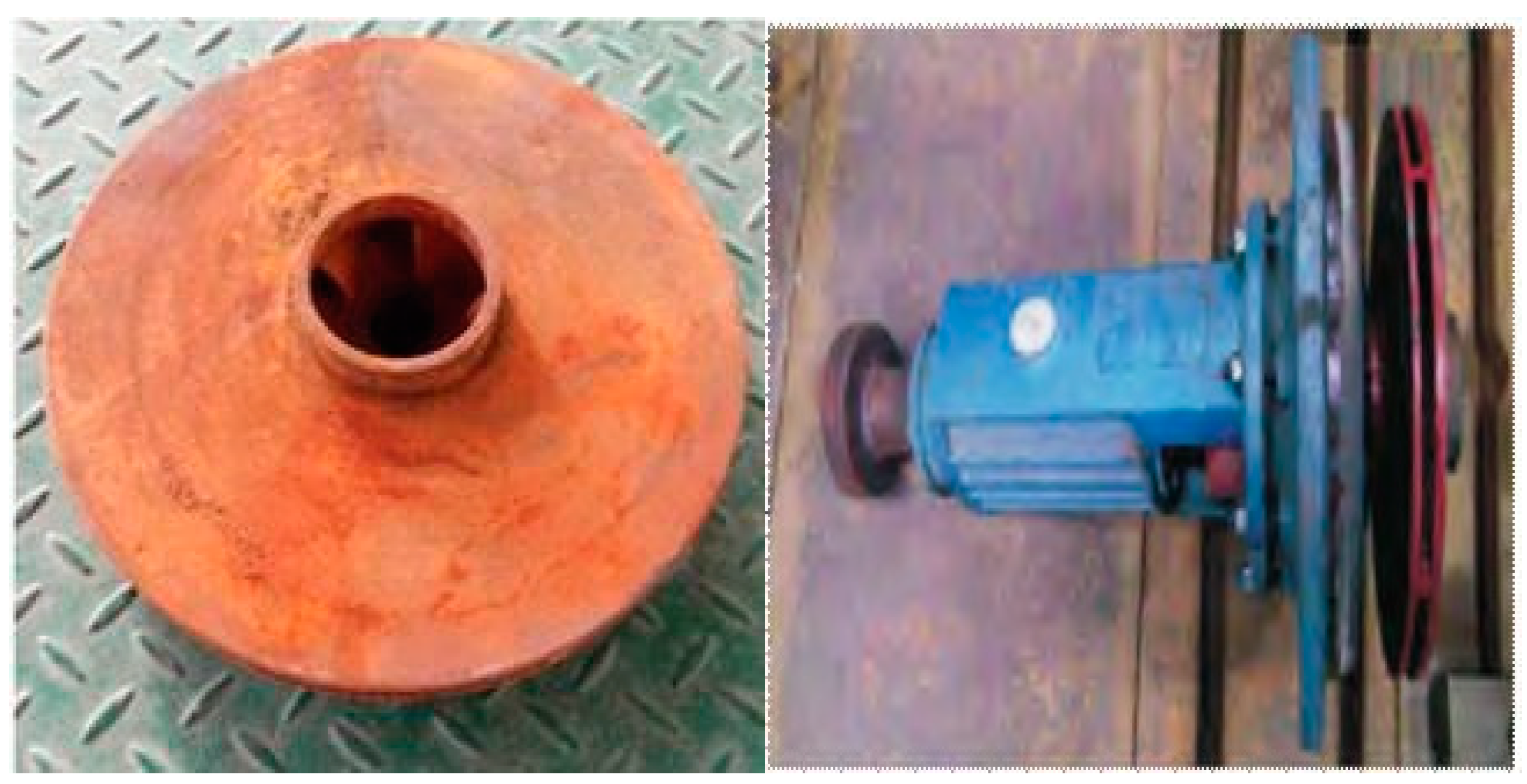
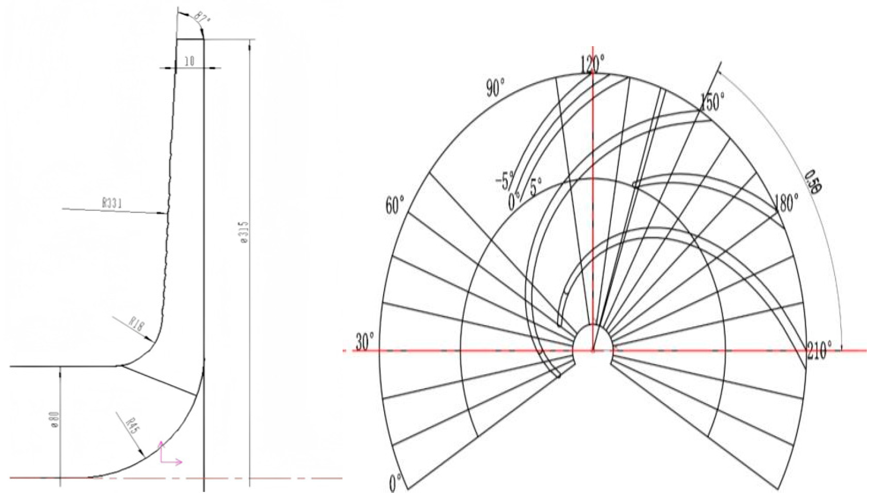
2.1. Original Hydraulic Turbine Parameters

The reverse rotation of the IS 80-50-315 centrifugal pump as a turbine was selected as the research object, as shown in Figure 1. The main external characteristic parameters of the pump include the flow rate (QP = 25 m3/h) and head (hp = 32 m), with a rotational speed (np) of 1450 r / m i n and a specific speed (nsp) of 33. The impeller and volute are its main core components. After reversing the centrifugal pump as turbine, the main geometric parameters of the turbine are shown in Table 1 [27].

2.2. Optimization and Improvement of the Pump-Turbine Model

The paper optimized and improved the turbine by adding split blades, and it was found that the size parameters of the short blades of the split blades were crucial [28]. The primary task is to design the inlet diameter, circumferential offset angle, outlet offset angle, and number of blades for short blades. According to the literature, the circumferential offset angle of the short blade is designed to be 0.5 θ (θ: the angle between two long blades), which is 30 degrees. The diameter of the short blade is 0.5 (D1 − D2) + D2, which is 197.5 mm, and the outlet offset angle is −5 degrees. Sakran, in his [29] review, mentions that the performance of centrifugal pumps is significantly affected by the number of vanes and that due to the existence of an optimal number of blades for hydraulic turbines with different parameters, four different blade numbers of split blades were designed in this article. Figure 2 shows the design diagram of the split blade scheme. Four types of split blade impellers (Z = (5 + 5), Z = (6 + 6), Z = (7 + 7), Z = (8 + 8)) were matched with the original impeller (Z = 6) in the same volute for numerical simulation. By comparing and analyzing the external characteristics, force characteristics (radial force, axial force), and fluid–structure coupling characteristics of four types of split blade impeller models with the original impeller model, the influence of different split blade impellers and the original impeller on the performance of the pump-turbine was studied. This provides a reference for selecting the optimal number of split blades for the pump as turbine and theoretical support for the efficient and stable operation of the pump as turbine unit. Under the condition of ensuring that the flow components, such as the volute and inlet/outlet extension sections, remain unchanged, Creo software (9.0.0) was used to perform 3D modeling on four types of split blade impellers, ultimately generating a 3D hydraulic model diagram of the split blade impellers, as shown in Figure 3.

3. Numerical Calculation Model

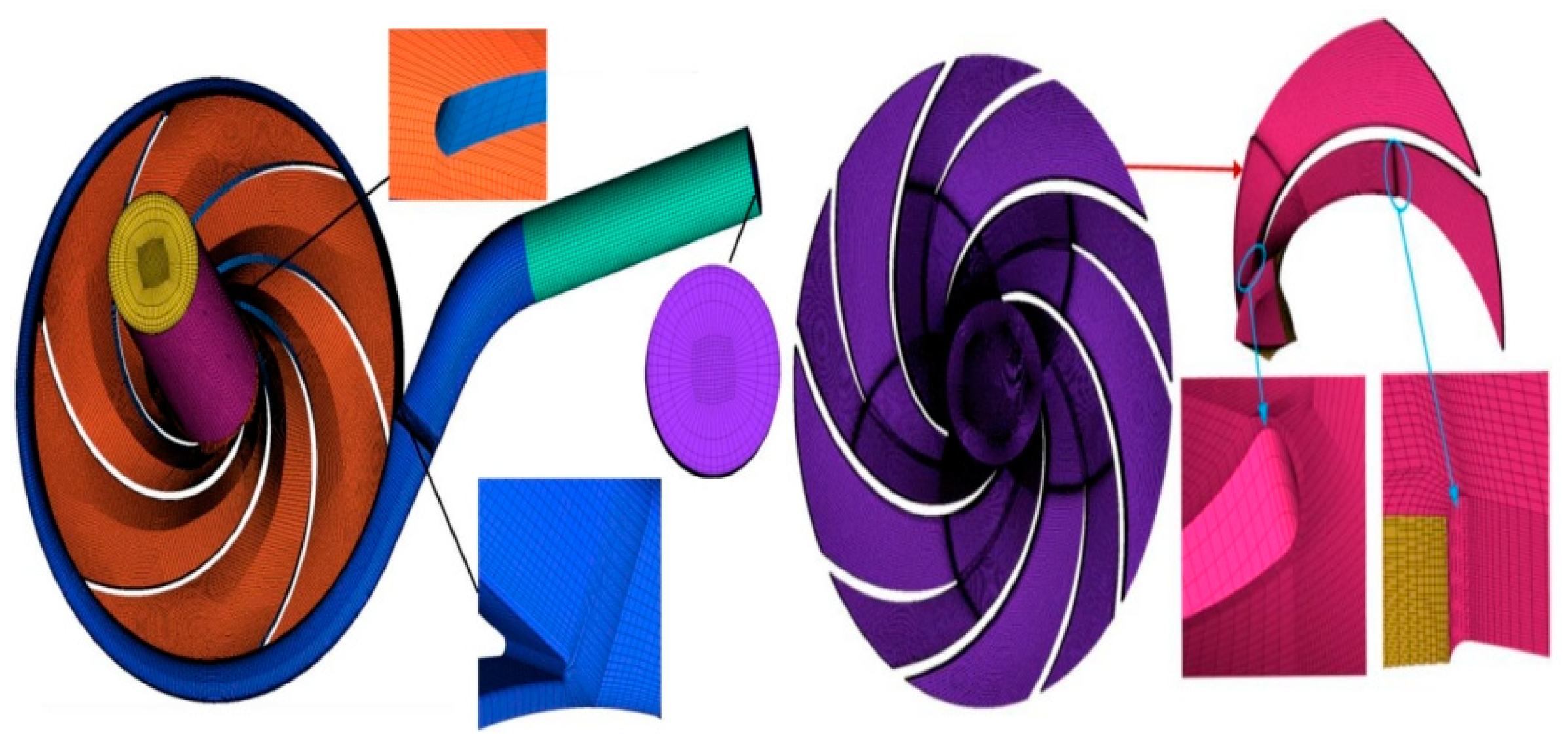
3.1. Three-Dimensional Modeling and Mesh Division

The calculation domain of the pump as turbine is mainly divided into four parts as follows: inlet section, impeller, volute, and outlet section. In order to ensure the smooth flow of fluid in the inlet and outlet sections, the inlet and outlet sections are designed to be four times the diameter of their respective interfaces. The 3D model of the pump as turbine was first created using Creo software; then, the fluid calculation domain was divided into hexahedral mesh structures using ANSYS ICEM software (19.2). The grids of each part in the calculation domain of the hydraulic turbine model are shown in Figure 4. In this study, the ICEM software was employed to perform grid generation for the constructed geometry, and grid independence verification was conducted using Richardson extrapolation. The Grid Convergence Index (GCI) [30] was applied to quantitatively evaluate the convergence of computational results, calculated as follows:
G G 21 C I = F s e a 21 / ( r 21 I 1 )
e a 21 = ( φ 1 φ 2 ) / φ 1
r 21 = N 1 / N 2 3
l = 1 ln r 21 | ln | ɛ 32 ɛ 21 | + q ( l ) |
q ( l ) = ln r 21 l s r 32 l s
s = s g n ( ɛ 32 / ɛ 21 )
In the formula, FS denotes the safety factor, typically set to 1.25; ε represents the relative error between numerical solutions from two grid sets; r indicates the grid refinement factor; l signifies the convergence order; φ1 and φ2 are the numerical solutions obtained from the first and second grid sets, respectively; and Δφ denotes the difference between the numerical solutions of the two grid sets.
The following three grid schemes were selected for precision validation: Scheme 1 (2.86 million elements), Scheme 2 (3.31 million elements), and Scheme 3 (3.74 million elements). Both hydraulic head and efficiency parameters were evaluated for grid accuracy verification. When the grid number reached 3.31 million, the GCIs for hydraulic head and efficiency were calculated as 0.42% and 0.67%, respectively, both below the 3% threshold. This confirms that Scheme 2 (3.31 million elements) satisfies the grid precision requirements. Detailed grid accuracy verification results are presented in Table 2.

3.2. Numerical Simulation Methods

In [31], Sakran mentioned that the fluid–solid coupling characteristics of centrifugal pumps could be better studied by using Fluent with CFX software (2022 R1); therefore, in this paper, the entire flow field numerical simulation was carried out using ANSYS CFX software, while the RNG k–ε turbulence model was used for solving. The entire flow component wall was set as a no-slip wall, and the coupling interfaces between the volute and impeller and between the impeller and the outlet section were set as dynamic and static interfaces. The fluid medium in the computational domain is set to clear water, the inlet boundary condition is set to velocity inlet, and the outlet boundary condition is set to pressure outlet. The pressure for each operating condition is set to 0.4 MPa. The solving mode is based on the SIMPLE algorithm, and the discretization method is based on a second-order upwind format. The convergence accuracy of the calculation is set to 10−6.
When performing unsteady calculations, the calculation domain needs to be selected with the appropriate time steps, and the head of the hydraulic turbine is monitored from one degree to six degrees, in intervals of one degree, based on the rotation angle of the impeller. The results are shown in Figure 5. In transient calculations, it is generally believed that an accurate solution can be obtained after the impeller completes 5–8 turns. In transient calculations, the impeller completes eight turns, and the last turn is taken for analysis. The horizontal axis of the graph is represented by the ratio of the impeller rotation time t to the impeller rotation period Tn (7.0Tn~8.0Tn). It can be observed from the graph that the fluctuation range of the transient head decreases as the time step is reduced. When the angle is within a range from 1° to 3°, smaller head fluctuations are observed. Finally, the method of calculating once with an impeller rotation of three degrees is determined. The time step t is set to 3.345 × 10⁻⁴ s; the rotation period T is set to 4.137 × 10⁻² s; and the total time is set to 0.331 s.

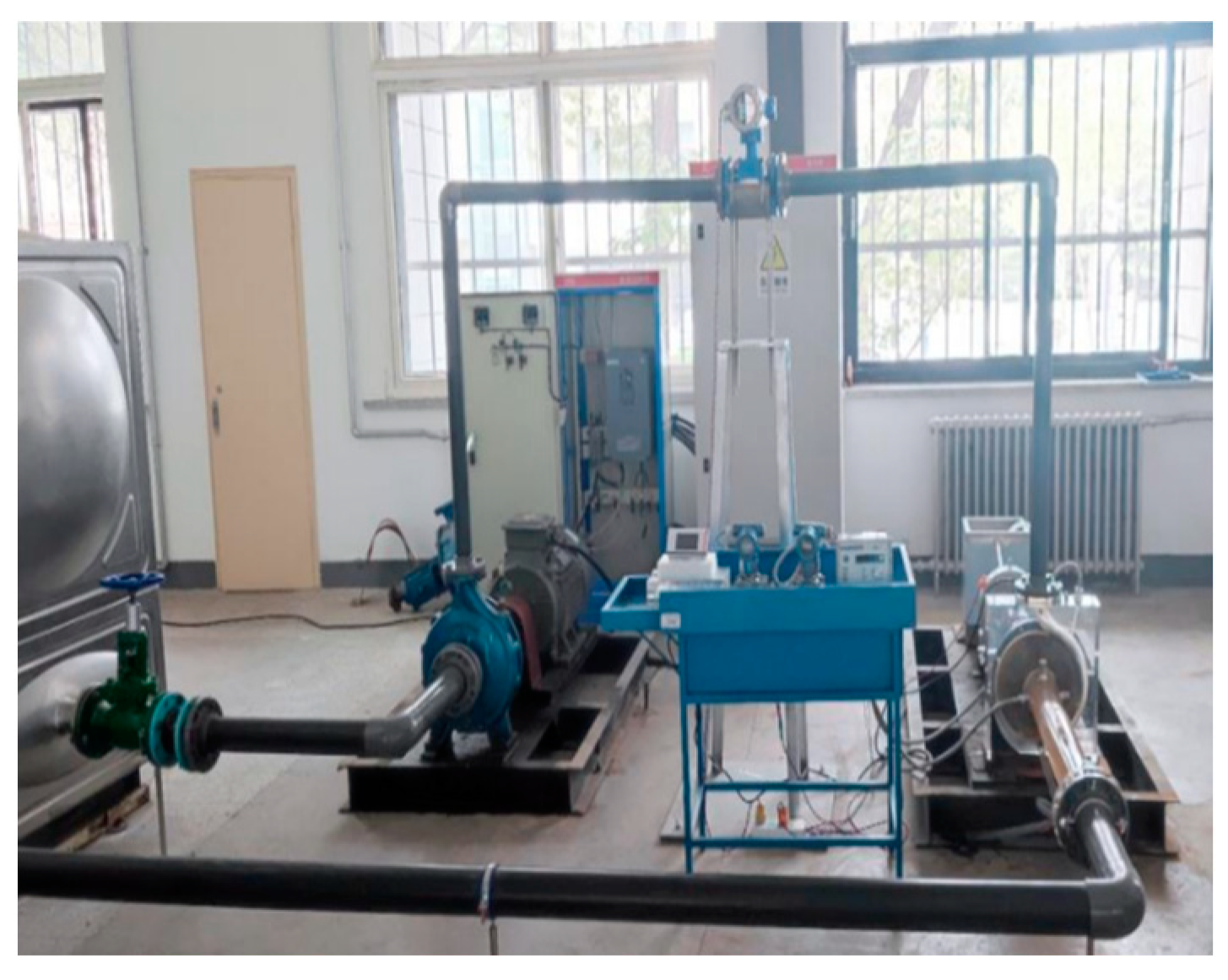
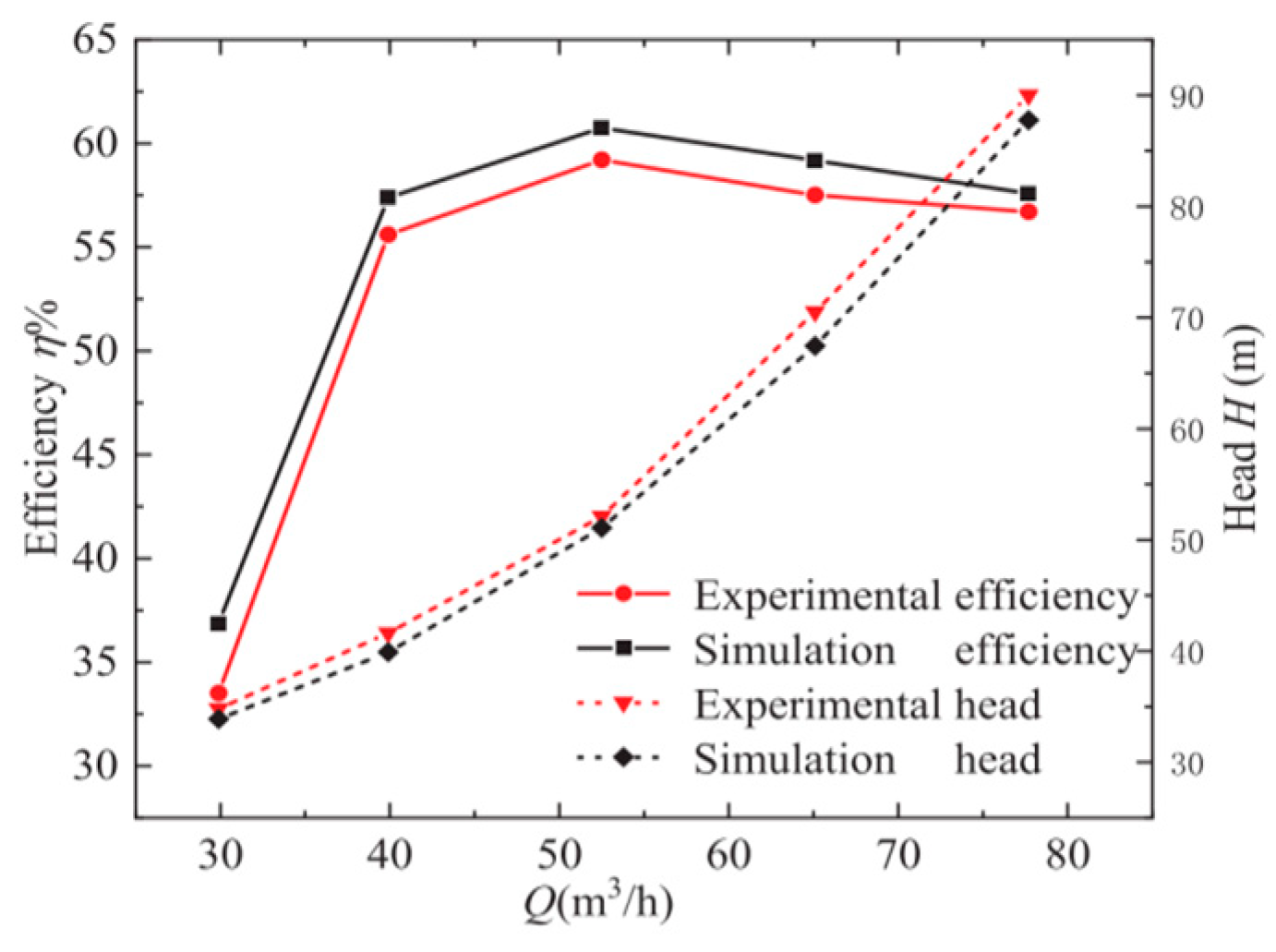
3.3. Verification of Numerical Calculation Accuracy

In order to verify the rationality and accuracy of the numerical calculation method, an external characteristic test was conducted on the original pump as turbine model, and the results of the external characteristic test were compared with the numerical calculation results. The test bench for the pump-turbine operation is shown in Figure 6 [27]. The required flow rate and pressure for the experiment are provided by a centrifugal pump, which controls the regulating valve to meet the test conditions required to operate the pump as turbine. The energy dissipation at the output shaft end of the pump as a turbine is achieved through a magnetic powder brake. The pressure sensor model is 335DP7E22M3B3C2 (Honeywell, Morris, NJ, USA) (range of 0.025 MP, accuracy of ± 0.25%), the electromagnetic flow meter model is AMF-80-10 (Shanghai Anjun Electronic Technology Co., Shanghai, China) (range of 0~130 m3h, accuracy of 0.5), and the torque sensor model is NJ1 (HBM, Darmstadt, Germany) (range of 0 ~ 100   N , accuracy of 0.2). The results of the external characteristic test are shown in Figure 7. The results showed that simulation efficiency and experimental efficiency improved with the increase in flow rate. The simulation head and experimental head showed a trend of first increasing and then decreasing with the increase in flow rate. The optimal operating point was determined to be at 2.1 QP, which is QBEP. Due to the lack of consideration of the hydraulic losses in the front and rear chambers of the impeller and the inlet and outlet pipelines during the numerical simulation process, the simulated head was lower than the test head, and the simulation efficiency was higher than the test efficiency. However, the two results were relatively close, with similar trends and errors within 5%. This indicates that using numerical simulation methods is feasible.

4. Result and Analysis

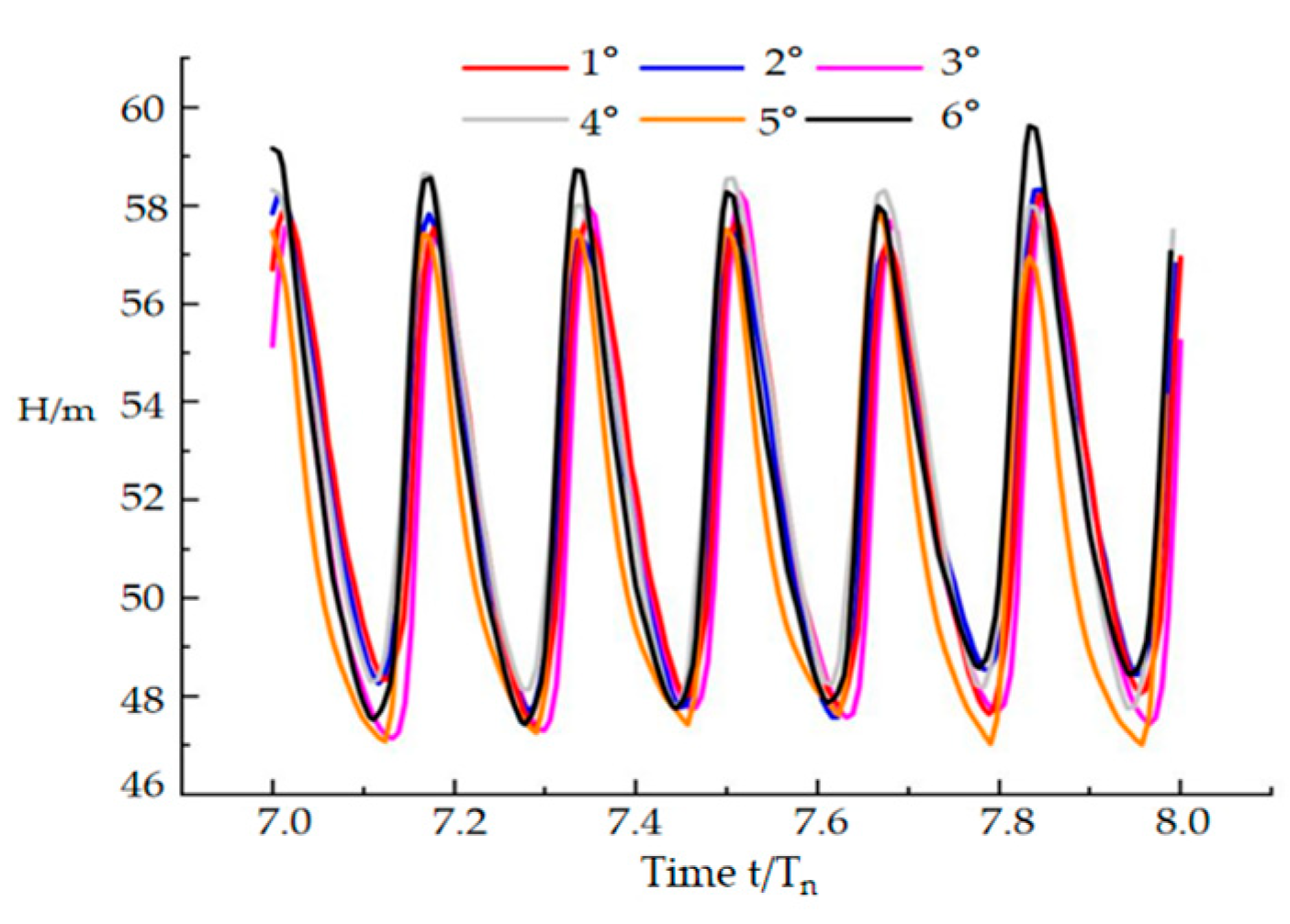
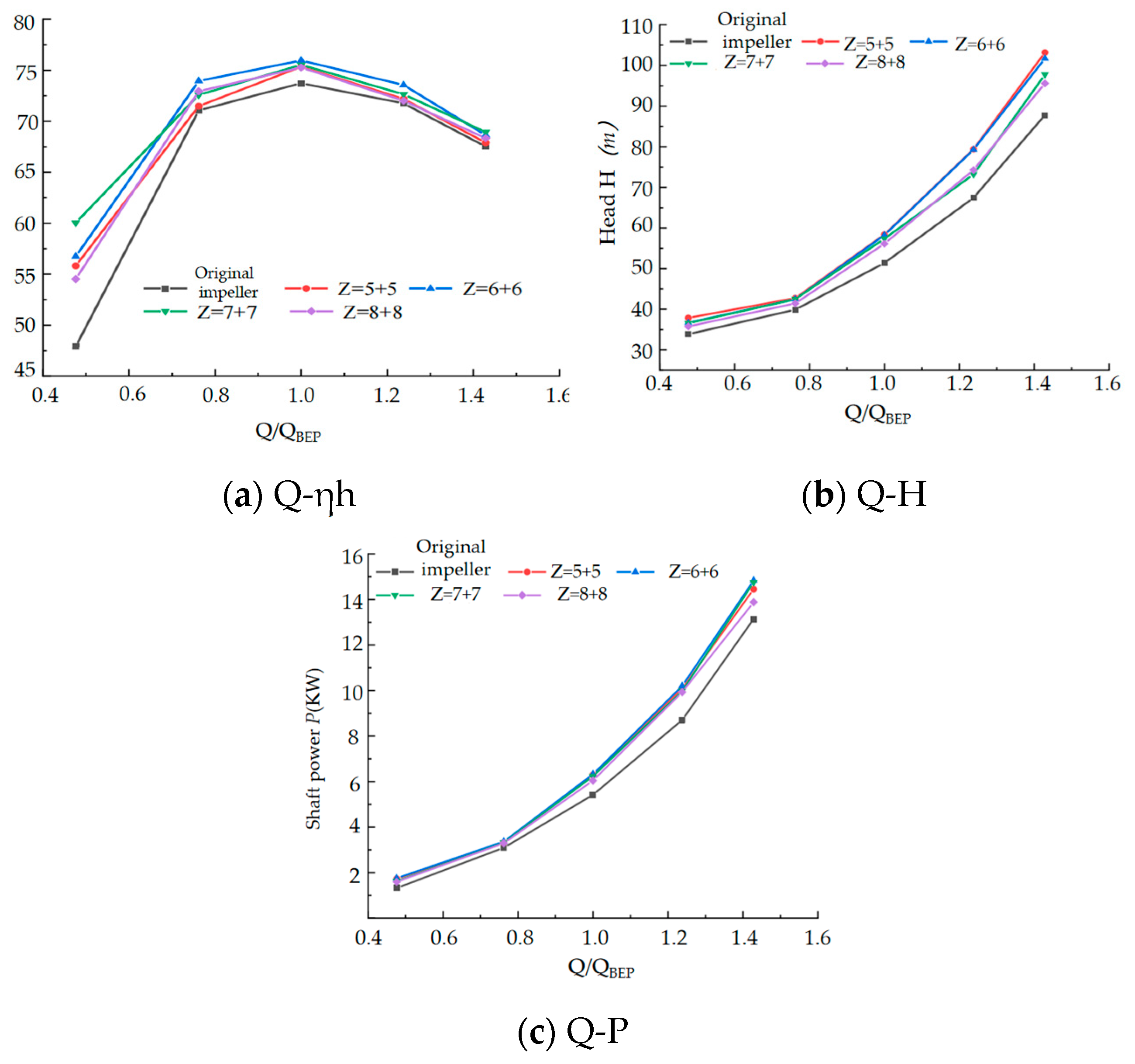
4.1. External Characteristic Analysis

Figure 8 presents the external characteristic curves of flow rate versus hydraulic efficiency, flow rate versus head, and flow rate versus shaft power for the original impeller and four split-bladed impellers under five operating conditions (0.48QBEP, 0.76QBEP, QBEP, 1.24QBEP, and 1.48QBEP), obtained through CFD numerical simulations. As observed in Figure 8, the variation trends of the external characteristics between the four split-bladed impellers and the original impeller are shown to be similar.
From Figure 8a, the optimal operating condition for all five impellers is confirmed to be QBEP. The hydraulic efficiency of the hydraulic turbine is observed to first increase to the optimal point (QBEP) and then gradually decrease with an increase in the flow rate. In the range of Q < 0.7QBEP, the hydraulic efficiency is ranked as Z = (7 + 7) > Z = (6 + 6) > Z = (5 + 5) > Z = (8 + 8) > Z6, where Z = (7 + 7) achieves the highest efficiency (25.37% higher than Z6), while Z = (8 + 8) exhibits the lowest efficiency (13.84% higher than Z6). For 0.76QBEP < Q < 1.4QBEP, the ranking shifts to Z = (6 + 6) > Z = (7 + 7) > Z = (5 + 5) > Z = (8 + 8) > Z6, with Z = (6 + 6) showing the highest efficiency. At Q > 1.4QBEP, Z = (7 + 7) is measured to have the highest efficiency, surpassing Z = (6 + 6) by 0.44%. Under the optimal condition (QBEP), the hydraulic efficiencies of the four split-bladed impellers are measured to be 2.20%, 3.03%, 2.44%, and 2.10% higher than that of the original impeller, respectively, with Z = (6 + 6) performing the best. The significant efficiency differences among the five impellers at low flow rates are attributed to the higher internal flow losses and recirculation caused by lower fluid velocities. At high flow rates, efficiency differences diminish, and Z = (6 + 6) is demonstrated to effectively address the issue of low efficiency in the high-efficiency operating zone.
Figure 8b illustrates that the head of both split-bladed and original impellers increases with flow rate. Across all conditions, the head of the split-bladed impellers is confirmed to exceed that of the original impeller. At low flow rates (Q < 0.76QBEP), the head growth rate of split-bladed impellers is observed to be moderate but accelerates gradually as the flow rate increases. Among them, Z = (5 + 5) and Z = (6 + 6) exhibit the fastest growth rates, with minimal differences in head values. At QBEP, the heads of the split-bladed impellers are measured to be 13.63%, 12.85%, 12.18%, and 9.26% higher than the original impeller, with Z = (6 + 6) achieving the maximum head.
Figure 8c displays the shaft power (recovery power) of the five impellers, reflecting the ability of high-pressure fluid to drive the impeller. The shaft power trends are shown to align with the head trends, increasing with flow rate, and the split-bladed impellers consistently outperform the original impeller. At QBEP, the shaft power of Z = (6 + 6) is measured to be the highest, surpassing the original impeller by 16.68%, confirming its superior energy recovery capability. Overall, the split-bladed impellers are validated to exhibit enhanced shaft power across all operating conditions.

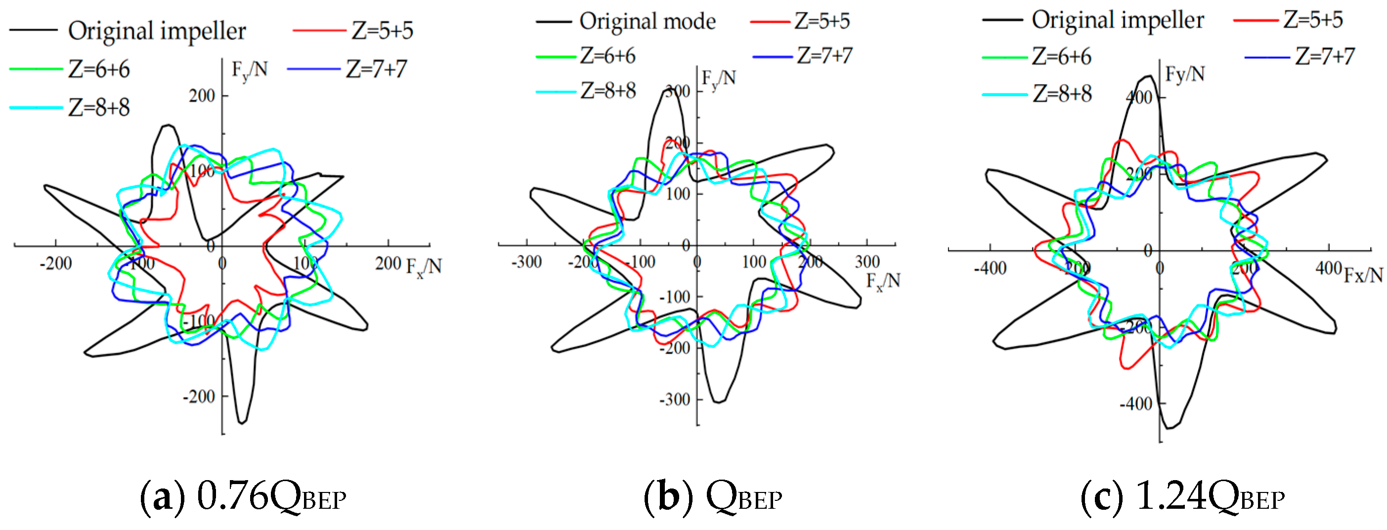
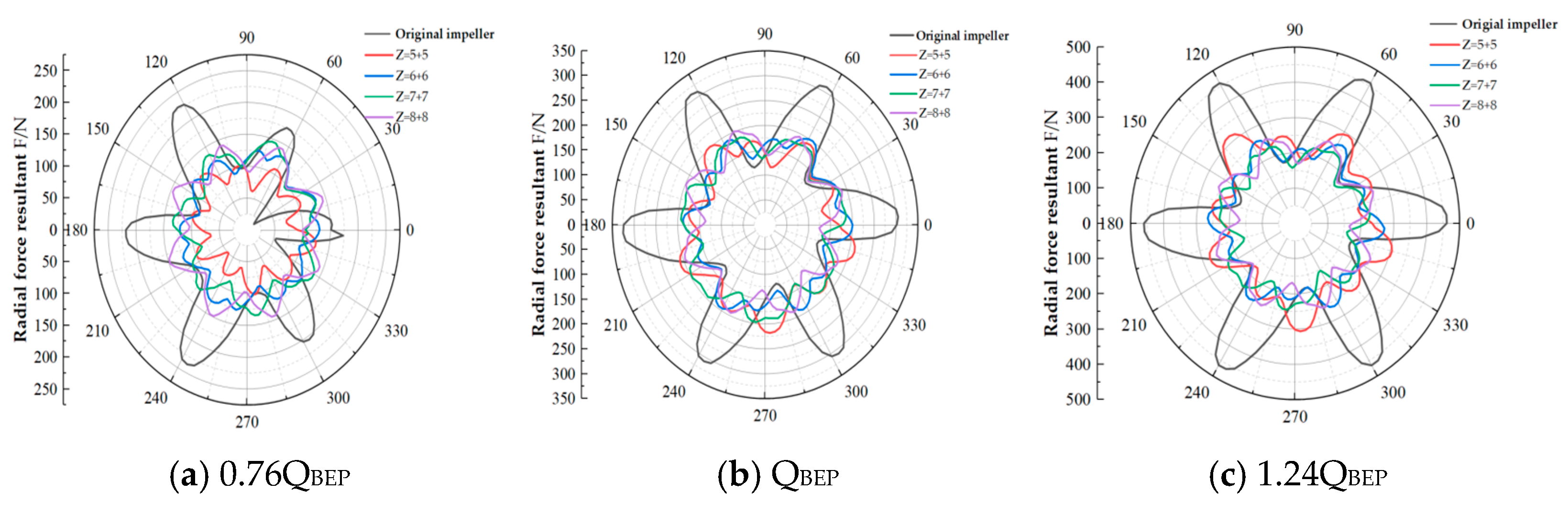
4.2. Transient Radial Force Analysis

Due to factors such as dynamic and static interference, the phenomenon of uneven flow and uneven circumferential pressure of the impeller during the operation of the pump as turbine has been observed. In addition, the structure of the pump as turbine is similar to that of a centrifugal pump, both of which have a spiral pressure chamber. When high-pressure fluid enters the impeller through the volute, the asymmetric distribution of internal fluid pressure is observed due to the different cross-sectional areas of the flow inside the volute. These phenomena result in the generation of radial forces on the impeller during the operation of the pump as turbine, and the presence of radial forces can cause vibrations in the unit during operation, leading to directional disturbances in the pump shaft and affecting the stable operation of the entire pump as turbine unit.
Therefore, it is necessary to study the radial force acting on the impeller of a pump as turbine under transient conditions. Numerical simulations were conducted on five impeller models, and transient radial forces were set through custom functions to detect the radial forces on the impeller blades, impeller front cover plate, and impeller rear cover plate. Three operating conditions (0.76QBEP, QBEP, 1.24QBEP) were selected for comparative analysis. Therefore, the radial forces experienced by the five impellers under different operating conditions were studied. The rotation axis of the impeller model is set as the Z-axis, and the combined radial force is as follows:
F = F x 2 + F y 2
In the formula, F x is the radial force component along the x direction, and F y is the radial force component along the y direction.
Figure 9 shows the radial force vector distribution of five impeller models within one rotation cycle under three operating conditions (0.76QBEP, QBEP, 1.24QBEP). It can be observed from the figure that the radial force vectors of the five impeller models exhibit periodic changes in the coordinate system under different operating conditions; that is, the number of “angles” of the radial force acting on the impeller is the same as the number of impeller blades. The original impeller has six angles in the coordinate system, while the split blade impeller (Z = 5 + 5) has ten angles in the coordinate system. It can be inferred that the periodic variation in transient radial force on the impeller is consistent with the number of impeller blades.
The figure shows that the radial forces exerted on five types of impellers increase with an increase in the flow rate. This is because under different operating conditions, the water head recovered by the pump as turbine is different, and the pressure inside the volute is different, resulting in different pressure distributions and flow velocities inside the impeller, generating different radial forces on the impeller. For the original impeller, the radial force vector is mainly concentrated in the second and fourth quadrants of the coordinate system. In contrast, the radial force vector distribution of the four types of split blade impellers is relatively concentrated. Through comparison, it is found that under all operating conditions, the radial force experienced by the four types of split blade impellers is smaller than that of the original impeller. Under low flow conditions, the radial force experienced by Z = (5 + 5) is the smallest, followed by Z = (6 + 6). However, Figure 9a shows that its uniformity is worse than that of Z = (6 + 6). Z = (6 + 6) experiences smaller radial force fluctuations under optimal and many other conditions, indicating better uniformity.
In order to further analyze the influence of the five impeller models on the radial force of the pump as turbine, Formula (7) was used to calculate the radial force components under various operating conditions in Figure 9. The resultant radial force of the last rotation cycle, the last circle, was calculated, as shown in Figure 10.
The number of occurrences of “angle number” matches the number of impeller blades, which means that the combined radial force acting on the five impellers exhibits periodic changes over time. Under different operating conditions, the combined radial forces acting on the five impellers show differences and increase with the flow rate increase.
For the original impeller, its radial force resultant fluctuates under different operating conditions, and the distribution is uneven under low flow conditions. However, as the flow rate increases, the radial force resultant shows a uniform distribution under optimal and high flow conditions. Under various operating conditions, the combined radial force of the four types of split blade impellers exhibits a relatively uniform distribution, and the combined radial force received is smaller than that of the original impeller. This indicates that the uneven distribution of circumferential pressure in the impeller can be improved by split blades, making the fluid’s pressure distribution more uniform. At the same time, the dynamic and static interference between the impeller and the volute is weakened to some extent, thereby reducing the radial force received by the impeller. Comparative analysis shows that Z = (5 + 5) experiences the slightest fluctuation in the combined radial force under low flow conditions. Under optimal and high flow conditions, the radial force fluctuations experienced by Z = (6 + 6) are relatively small.
In order to more intuitively analyze the magnitude of the radial force resultant acting on the five impeller models, the maximum value of the radial force resultant experienced by each impeller under the optimal operating conditions was extracted, as shown in Table 3. From the table, it can be seen that the maximum radial force of the four types of split blade impellers is significantly lower than the combined radial force of the original impellers, and the range of radial force fluctuations is much smaller than that of the original impellers. For the four types of split blade impeller models, the fluctuation range of Z = (5 + 5) is the smallest, followed by Z = (6 + 6), and Z = (8 + 8), which has the most extensive fluctuation range. Although the fluctuation range of Z = (5 + 5) is relatively small, compared with Z = (6 + 6), the maximum and minimum values of the radial force resultant are more significant, with the maximum value being 8.78% larger than Z = (6 + 6). The minimum value is 23.13% larger than Z = (6 + 6). In addition, among the four types of split blade impellers, the maximum radial force value of Z = (6 + 6) is determined to be the smallest.

4.3. Transient Axial Force Analysis

The axial force in a pump as turbine mainly comprises three parts as follows [32]: (1) The asymmetry between the front and rear cover plates of the impeller leads to the generation of external cover plate force. (2) Due to the twisted shape of the impeller blades, the axial force is generated when the impeller rotates. (3) During the rotation of the impeller, the pressure difference acting on the internal fluid generates axial force. The numerical simulation method was used to calculate the transient axial force of five impeller models. The setting of the axial force only requires detecting the axial force on the impeller blades and the front and rear cover plates through a custom function. Three external characteristic operating conditions (0.76QBEP, QBEP, 1.24QBEP) were selected for comparative analysis.
The rotating axis of the pump as turbine model is set as the Z-axis, and the transient axial force is set. Custom functions monitor the impeller blades and the impeller’s front and rear cover plates to obtain the transient axial force FZ, and the dimensionless axial force coefficient C F is introduced to determine the transient axial force.
C F = F z π ρ g H r 2 2
In the formula, F Z represents the transient axial force, N; ρ represents the medium density, kg/ m 3 ; r 2 represents the impeller radius, m; and H represent the head, m.
Formula (8) is used to render the transient axial force of five impeller models dimensionless to obtain the axial force coefficient curve over time under different operating conditions during a rotation cycle, as shown in Figure 11. In the figure, the horizontal axis represents the impeller’s rotation time, and the vertical axis represents the axial force coefficient.
The periodic variation in axial force coefficients over time was observed for five impeller models, and it was found that the axial force of the five impeller models exhibited periodic fluctuations related to the number of long and short blades. As the flow rate increases, the axial force coefficients of the five impeller models gradually decrease. This is because, with the increase in flow rate, the high-pressure fluid exerts greater force inside the impeller, which can be partially offset by the opposite direction of axial force. Moreover, the axial force coefficient fluctuation range of the four types of split blade impellers is smaller than that of the original impeller under various operating conditions, indicating that split blade impellers can improve the stability of unit operation. Figure 11a shows that the axial force coefficient of the original impeller fluctuates significantly under low flow conditions, mainly due to the unstable flow under low flow conditions. The axial force variation in each impeller is Z6 > Z = (5 + 5) > Z = (7 + 7) > Z = (6 + 6) > Z = (8 + 8). The fluctuation range of Z = (8 + 8) is the smallest, which is 16.67% smaller than the original impeller. The maximum fluctuation of Z = (6 + 6) is 10.56% smaller than the original impeller. From Figure 11b,c, it can be seen that under low and high flow conditions, the axial force fluctuation range of the five impeller models is the same, all of which are Z = 6 > Z = (7 + 7) > Z = (8 + 8) > Z = (5 + 5) > Z = (6 + 6). The fluctuation range of Z = (6 + 6) is the smallest, and its maximum axial force coefficient is 19.75% and 15.45% smaller than the original impeller under two operating conditions, respectively. The above analysis indicates that the split blade impeller can make the flow inside the impeller more uniform, thereby making the fluid pressure on the front and rear cover plates of the impeller more uniform and weakening the axial force on the impeller, making the operation of the pump as turbine unit safer and more stable.

5. Analysis of the Fluid–Structure Coupling Characteristics of the Rotor System

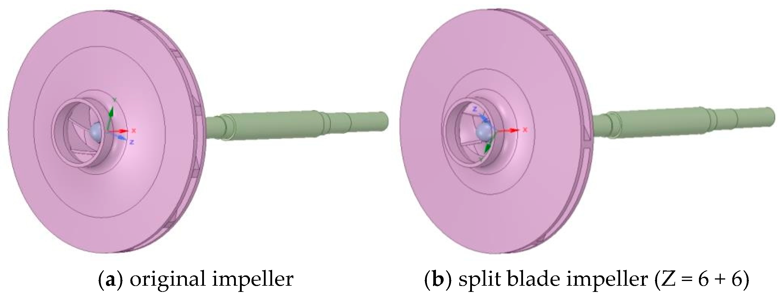
5.1. Computation Model

The calculation domain of the pump as turbine rotor system consists of the impeller, shaft, and nut. The solid domain impeller model obtained based on the original impeller fluid domain model is used to ensure the accuracy of the matching between the solid domain and fluid domain in fluid–solid coupling calculations. Then, Creo software is used to establish other rotor components in the solid domain of the original impeller and split blade impeller, and the calculation model shown in Figure 12 is obtained.

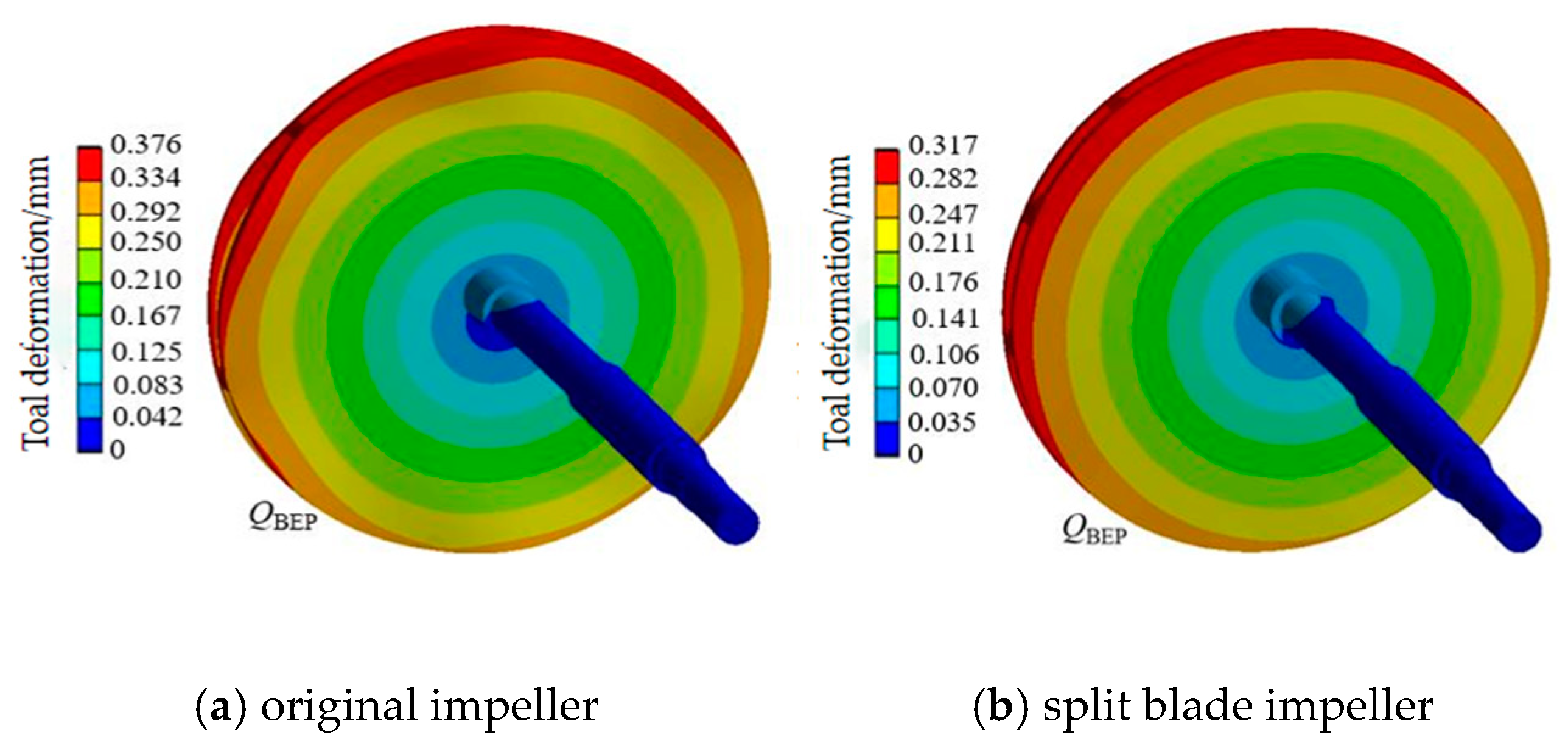
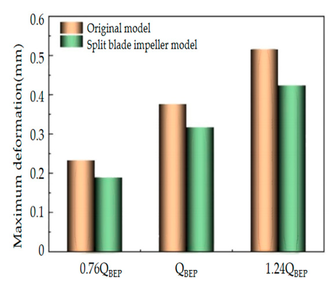
5.2. Deformation Analysis of the Rotor System

Due to the complexity of the flow inside the pump as turbine, the asymmetry of the structure, and the dynamic static coupling between the impeller and the volute, the high-pressure fluid passing through the volute and entering the impeller interior causes flow instability. The pressure pulsation generated by the unsteady flow inside the pump as turbine will affect the stress distribution of the structure, and the stress distribution will also be generated when the impeller rotates. The existence of these stresses causes the deformation of the pump as turbine structure, which affects the safety and stability of the unit’s operation. Therefore, it is necessary to conduct stress–strain analysis on the pump as turbine rotor system. This paper analyzed the original impeller model and the Z = 6 + 6 split blade impeller model for fluid–structure coupling.
Figure 13 shows the deformation distribution of the rotor components of the pump as turbine model under optimal operating conditions. From the figure, it can be observed that both the original impeller model and the split blade impeller model have the maximum deformation area of the rotor components appearing in a partial area at the impeller inlet (at the edges of the front and rear cover plates of the impeller inlet), indicating that the deformation in this area is close to the position of the volute tongue, which is not only affected by fluid pressure pulsation, but also by the volute tongue. At the same time, the area with the slightest deformation appears at the minimum end of the pump shaft diameter (where it is connected to the coupling). Table 4 shows the strain ratios for different impellers. The deformation factor is defined as δmax/Lref (Lref = 200 mm). The results indicate that the impeller with a Z = (6 + 6) configuration exhibits the lowest deformation factor (0.035), which has been reduced by 16.7% compared to the original impeller.
As the flow rate increases, the deformation of the rotor components of the two pumps as turbine models gradually increase, and the rotor components’ deformation law is similar. The minimum deformation of rotor components occurs on the shaft. For the original impeller model, significant deformation occurred in the impeller. As the flow rate increases, both the impeller’s front and rear cover plates show slight deformation near the inlet, and there is no connection between the two cover plates at this deformation point and the blades. This is mainly due to the high flow velocity of the high-pressure fluid at the inlet, which can impact the blades and impeller inlet area, resulting in severe deformation. For the split blade impeller model, the variation pattern of its rotor components is similar to that of the original impeller. The deformation of the front and rear cover plates of the impeller at the inlet after adding short blades is smaller than that of the original model, indicating that increasing the number of blades can weaken the deformation of the pump as turbine rotor components to a certain extent, especially on the impeller. In summary, by comparing the deformation cloud maps of the two models under different operating conditions, the deformation distribution of the rotor components was the same. The deformation at the inlet of the impeller was relatively large, and the deformation on the shaft remained constant. Except for a small deformation at the connection with the impeller, the deformation of the entire rotor component of the split blade impeller model was weaker than that of the original impeller model, indicating that changes in the flow rate and the number of impeller blades have a particular impact on the deformation of the rotor components.
In order to better analyze the maximum deformation of the rotor system under different operating conditions, the maximum deformation of the rotor components of two models under different operating conditions was compared and analyzed, as shown in Figure 14.
It can be seen that the maximum deformation of the turbine rotor components of both pumps shows an upward trend under different operating conditions. This is because after adding short blades in two adjacent flow channels of the original impeller, the high-pressure fluid shares the pressure and stress it experiences after entering the impeller, reducing the deformation of the rotor components. On the other hand, after adding split blades, the impeller is connected to the front and rear cover plates, making the impeller sturdier. Compared with the original model, the maximum deformation of the split blade impeller rotor components under various operating conditions decreased by 0.044 mm, 0.059 mm, and 0.092 mm, respectively. Therefore, the deformation patterns of the rotor components in the two hydraulic turbines as models are similar. Adding split blades can effectively share the pressure and stress on the impeller, reducing deformation. This indicates that adding an appropriate number of blades for the pump as turbine can effectively reduce the deformation of their rotor components.

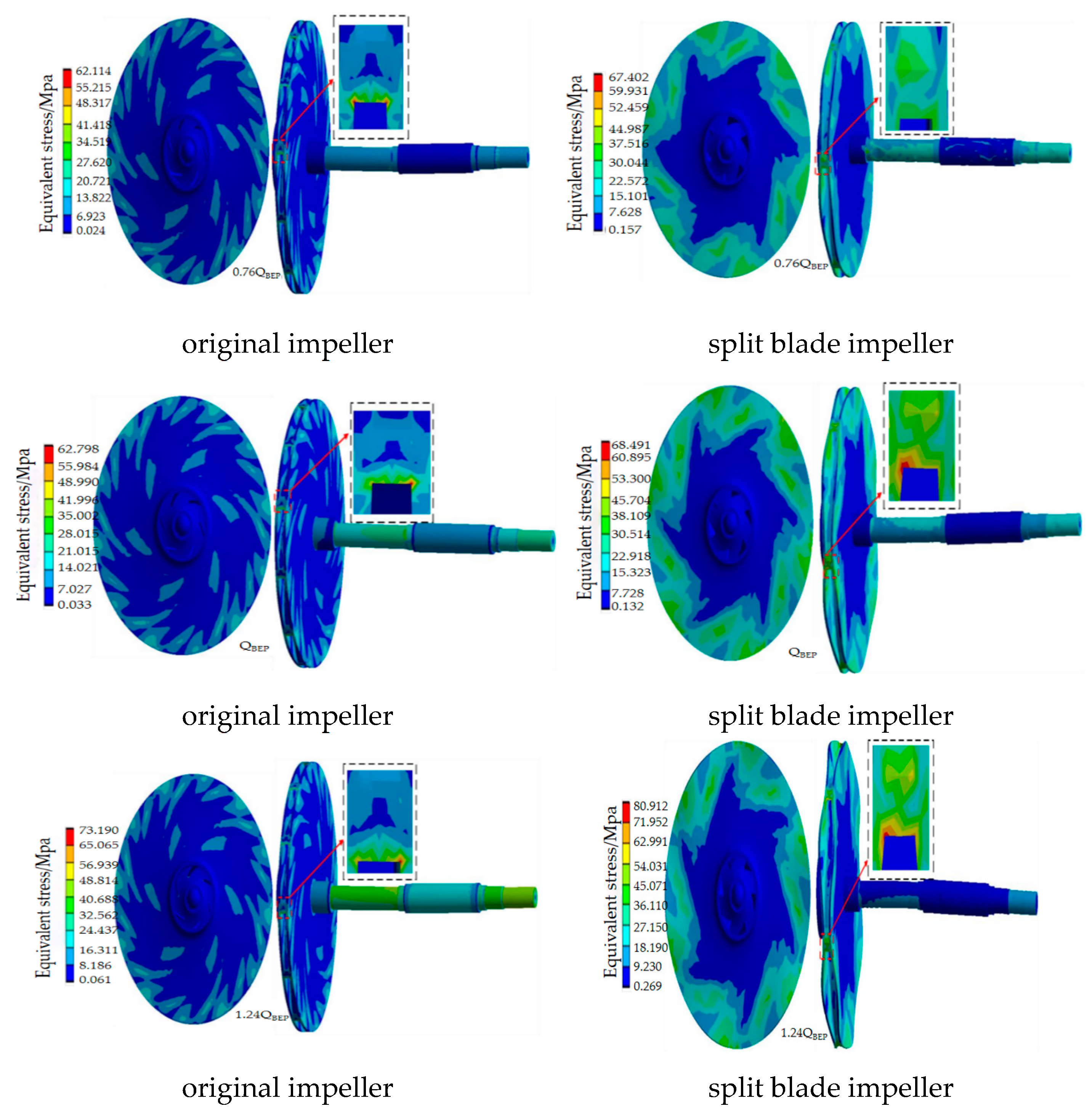
5.3. Equivalent Stress Analysis of the Rotor System

As a yield criterion, Von Mises stress is used to accurately and comprehensively consider the first, second, and third principal stresses to measure the fatigue and failure of structures. The value of the yield criterion is called equivalent stress, which is referred to as the equivalent stress in ANSYS post-processing software. In order to analyze the distribution of the standard form equivalent stress of rotor components in two pump turbine models under different operating conditions, this paper selected three operating conditions (0.76QBEP, QBEP, 1.24QBEP) for analysis.
Figure 15 shows the stress distribution of two pumps as turbine model rotor components under different operating conditions. The figure shows that the stress distribution patterns of the two pumps as turbine model rotor systems are similar. The equivalent stress shows a gradually increasing trend from the impeller outlet to the impeller inlet. It reaches its maximum near the impeller inlet and is mainly concentrated on connecting the impeller’s front and rear cover plates and the blades. This is because, during the process of high-pressure fluid acting on the impeller, the top of the blade is connected to the front and rear cover plates, causing the high-pressure fluid to experience significant stress and instantaneous deformation at the connection point during the inflow process. On the other hand, due to the complexity of the pump as turbine’s internal flow, the impeller’s asymmetry, and the dynamic static coupling between the impeller and the volute, stress is generated in the inlet area of the impeller, resulting in significant stress. In addition, the blades are twisted, causing the inlet position of the impeller blades to be the weak area of the entire blade, where significant stress concentration occurs. On the pump shaft, the maximum equivalent stress occurs at the most minor end of the shaft diameter, and the minimum equivalent stress occurs at the most significant end of the shaft diameter. This is due to the asymmetric structure of the pump as turbine, which causes the stress generated by the unsteady internal flow of the impeller during rotation to act on the pump shaft, resulting in the directional deflection of the shaft. As the flow rate increases, the stress on the rotor components of the two pumps as turbine models gradually increases. The stress variation law of the rotor components is basically similar, with the maximum stress occurring at the inlet of the impeller and the connection between the front and rear cover plates and the blades and the minimum stress occurring at the outlet of the impeller and the partial areas of the front and rear cover plates, as well as at the maximum pump shaft diameter. Under the same operating conditions, the stress and deformation of the impeller of two pumps as turbine models exhibit different changes. Among them, the stress distribution on the original model impeller is mainly concentrated at the inlet of the impeller, and there are also some larger stress areas near the outlet of the front and rear cover plates. In contrast, the stress distribution on the split blade model impeller is mainly concentrated at the inlet of the impeller. For the original impeller model, the significant stress on the rotor component impeller is mainly concentrated at the impeller inlet, and the equivalent stress on the impeller gradually increases with an increase in the flow rate. Due to the increase in stress, the deformation of the front and rear shrouds was found to increase gradually. For the split blade impeller model, the maximum stress values of the rotor components were also found to occur at the inlet of the impeller. However, under various operating conditions, the maximum equivalent stress values were lower than those of the original impeller. The stress at the front and rear shrouds was also lower than that of the original impeller, and the deformation of the front and rear shrouds was almost negligible compared to the original impeller. This indicates that the presence of split blades can reduce the stress distribution on the rotor components of the impeller, thereby reducing the impact on the shrouds. The comparative analysis found that the maximum equivalent stress values for both pump as turbine models occur at the inlet of the impeller, more specifically, at the connection between the blades and the front and rear shrouds. The stress variations in the pump shaft were similar for both models. Additionally, the maximum equivalent stress values of the split blade impeller model were lower than those of the original impeller model, indicating that changes in the flow rate and the number of blades have a particular influence on the stress distribution of the rotor components.
In addition, as shown in Figure 16, the maximum equivalent stress on the rotor components of the turbine model under different operating conditions is compared. The graph shows that under different operating conditions, the equivalent stress values of the two pumps as rotor components of the turbine model show an upward trend, with higher growth rates at high rather than low flow rates. Under the same operating conditions, it was found that the maximum equivalent stress of the rotor components in the split blade impeller model was generally lower than that in the original impeller model. This is because the presence of split blades allows more blades to share the pressure and stress experienced by the impeller. Compared with the original impeller model, the maximum equivalent stress of the split blade impeller rotor components decreased by 5.29 MPa, 5.51 MPa, and 7.72 MPa, under various operating conditions, respectively. Under the 1.24QBEP operating condition, the rotor components experience the highest equivalent stress values, 80.91 MPa and 73.19 MPa, for the two pumps as turbine models, respectively. The maximum equivalent stress values for both models occur on the impeller, which is made of 304 stainless steel and yields an ultimate stress of 310 MPa. According to the formula n s = σ s / σ (where n s is the safety factor, σ s is the material yield stress, and σ is the allowable stress), the safety factors for the impellers of the two models can be calculated as 3.83 and 4.23, respectively. It can be seen that under high flow conditions, the safety factors of both impeller models are more significant than one, while the safety factor of the split blade impeller model is higher. This indicates that an appropriate increase in the number of blades (split blades) can effectively improve the deformation of the rotor component impeller and increase its service life

6. Conclusions

(1) The radial force acting on the impeller can be reduced by the split blade impeller, indicating that the circumferential pressure distribution of the impeller can be improved by the split blade, making the fluid entering the impeller more uniform. It was demonstrated through comparisons under different operating conditions that using a split blade impeller results in a more uniform internal flow within the impeller. This leads to a more even distribution of fluid pressure on the front and rear shrouds, thereby reducing the axial force experienced by the impeller. Consequently, the pump as turbine unit can operate more safely and stably.
(2) Both the radial force vector and the combined radial force gradually increased with the flow rate increase in all five impeller models. This is due to the different recovery heads of the pump as turbine under various operating conditions, the different pressures inside the volute, and the different circumferential pressures of the impeller, which result in different radial forces. In addition, split blades can improve the problem of uneven circumferential pressure distribution in the impeller, making the fluid flow entering the impeller and the pressure distribution more uniform, so that the radial force on the split blade impeller is much smaller than that on the original impeller under various working conditions.
(3) The deformation patterns of the rotor components in the two pump models are similar. The pressure and stress on the impeller can be effectively shared by the increased split blades, resulting in reduced deformation. This indicates that for a pump as turbine, the deformation of its rotor components can be effectively reduced by appropriately increasing the number of blades. In practical engineering, if there is a specific requirement for minimizing the deformation of turbine rotor components in pumps, the deformation of the rotor component impeller can be effectively improved and met by appropriately increasing the number of blades.

Author Contributions

Study conception and design: F.S. and X.Z. Data collection: X.Z. and G.Z. Analysis and interpretation of results: G.Z., D.Z., P.W. and H.Z. Draft manuscript preparation: X.Z. All authors have read and agreed to the published version of the manuscript.

Funding

The authors would like to thank the support of the Innovation Fund for College Teachers of Department Education of Gansu (No. 2024A-021); the Colleges and Universities Industrial Support Program Projects of Gansu Province (Grant No. 2020C-20); the Key Laboratory of Fluid and Power Machinery, Ministry of Education, Xihua University (Grant No. szjj2019-016, LTDL2020-007); and the Key Research and Development Program of Gansu Province—Industrial Project (No. 25YFGA021).

Data Availability Statement

All the data used in the study are included in the manuscript.

Acknowledgments

The authors would like to thank the members of the School of Energy and Power Engineering, Lanzhou University of Technology.

Conflicts of Interest

The authors declare that they have no conflicts of interest to report regarding the present study.

References

  1. Liu, Z.; Xiao, Y.; Wang, C.P.; Zhu, Y.L.; Liu, S.H.; Cui, Y.K.; Yin, X.L. Numerical Analysis of Hydraulic Characteristics of Turbine Type Energy Recovery Integrated Machine. J. Hydroelectr. Eng. 2021, 40, 131–140. [Google Scholar]
  2. Barbarelli, S.; Amelio, M.; Florio, G. Predictive Model Estimating the Performances of Centrifugal Pumps Used as Turbines. Energy 2016, 107, 103–121. [Google Scholar]
  3. Zhang, D.; Qi, B.; Zhao, R.; Zhang, Q. Optimization Design of a Hydraulic Model for Energy Recovery Turbine in Seawater Desalination. J. Irrig. Drain. Eng. 2021, 39, 649–654. [Google Scholar]
  4. Williams, A. Pumps as Turbines Used with Induction Generations of Stand-Alone Micro-Hydroelectric Power Plants. Ph.D. Thesis, Nottingham Polytechnic, Nottingham, UK, 1992. [Google Scholar]
  5. Yang, H.; He, Q.; Huang, X.; Yang, M.; Bi, H.; Wang, Z. Experimental and Numerical Investigation of Rotor–Stator Interaction in a Large Prototype Pump–Turbine in Turbine Mode. Energies 2022, 15, 5523. [Google Scholar] [CrossRef]
  6. Wang, S.; Zhang, L.; Yin, G. Numerical Investigation of the FSI Characteristics in a Tubular Pump. Math. Probl. Eng. 2017, 2, 7897614. [Google Scholar]
  7. Li, Y.; Guo, D.; Fan, Z.; Du, J. Effects of Different Blade Numbers on Radial Exciting Force of Lobe Pump Rotor. Int. J. Fluid Mach. Syst. 2020, 13, 281–291. [Google Scholar]
  8. Yu, H.; Wang, T.; Dong, Y.; Gou, Q.; Lei, L.; Liu, Y. Numerical Investigation of splitter Blades on the Performance of a Forward-Curved Impeller Used in a Pump as Turbine. Ocean Eng. 2023, 281, 114721. [Google Scholar] [CrossRef]
  9. Hu, J.; Zhao, Z.; He, X.; Zeng, W.; Yang, J. Design Techniques for Improving Energy Performance and S-Shaped Characteristics of a Pump-Turbine with split Blades. Renew. Energy 2023, 212, 333–349. [Google Scholar]
  10. Benra, F.; Dohmen, H.; Wan, B. Determination of Pump Impeller Deflections: Comparison of FSI-Simulation Measurements. In Proceedings of the ASME Fluids Engineering Division Summer Meeting, Miami, FL, USA, 17–20 July 2006; ASME: New York, NY, USA, 2006. [Google Scholar]
  11. Kobayashi, K.; Ono, S.; Harada, I.; Chiba, Y. Numerical Analysis of Stress on Pump Blade by One-Way Coupled Fluid-Structure Simulation. J. Fluid Sci. Technol. 2010, 5, 219–234. [Google Scholar]
  12. Benra, F.K.; Dohmen, H.J.; Pei, J.; Schuster, S.; Wan, B. A Comparison of One-Way and Two-Way Coupling Methods for Numerical Analysis of Fluid-Structure Interactions. J. Appl. Math. 2011, 2011, 853560. [Google Scholar]
  13. Adkins, D.R.; Brennen, C.E. Analyses of Hydrodynamic Radial Forces on Centrifugal Pump Impellers. J. Fluids Eng. 1988, 110, 20–28. [Google Scholar]
  14. Barrio, R.; Fernández, J.; Blanco, E.; Parrondo, J. Estimation of Radial Load in Centrifugal Pumps Using Computational Fluid Dynamics. Eur. J. Mech. B Fluids 2011, 30, 316–324. [Google Scholar]
  15. Yang, S.S.; Kong, F.Y.; Qu, X.Y.; Jiang, W.M. Influence of Blade Number on the Performance and Pressure Pulsations in a Pump Used as a Turbine. J. Fluids Eng. 2012, 134, 12–23. [Google Scholar]
  16. Harano, M.; Tani, K.; Nomoto, S. Practical Application of High-Performance Francis-Turbine Runner Fitted with split Blades at Ontake and Shinkurobegawa No.3 Power Stations of the Kansai Electric Power Co., Inc. Eng. Appl. Sci. 2006, 55, 109–113. [Google Scholar]
  17. Gölcü, M.; Pancar, Y.; Sekmen, Y. Energy Saving in a Deep Well Pump with split Blade. Energy Convers. Manag. 2006, 47, 638–651. [Google Scholar]
  18. Solano, J.P.; Pinilla, V.; Paniagua, G.; Lavagnoli, S.; Yasa, T. Aero-Thermal Investigation of a Multi-split Axial Turbine. Int. J. Heat Fluid Flow 2011, 32, 1036–1046. [Google Scholar] [CrossRef]
  19. Adu, D.; Du, J.; Darko, R.O.; Ofosu Antwi, E.; Khan, M.A.S. Numerical and Experimental Characterization of split Blade Impact on Pump as Turbine Performance. Sci. Prog. 2021, 104, 36850421993247. [Google Scholar] [CrossRef]
  20. Ji, Y.; Yang, Z.; Ran, J.; Li, H. Multi-Objective Parameter Optimization of Turbine Impeller Based on RBF Neural Network and NSGA-II Genetic Algorithm. Energy Rep. 2021, 7, 584–593. [Google Scholar]
  21. Liu, H.; Xu, H.; Ellison, P.J.; Jin, Z. Application of Computational Fluid Dynamics and Fluid–Structure Interaction Method to the Lubrication Study of a Rotor–Bearing System. Tribol. Lett. 2010, 38, 325–336. [Google Scholar]
  22. Cai, J.-C.; Chen, H.-J.; Brazhenko, V.; Gu, Y.-H. Study of the Hydrodynamic Unsteady Flow Inside a Centrifugal Fan and Its Downstream Pipe Using Detached Eddy Simulation. Sustainability 2021, 13, 5113. [Google Scholar] [CrossRef]
  23. Li, Q.; Liu, S.L.; Pan, X.H.; Zheng, S.Y. A New Method for Studying the 3D Transient Flow of Misaligned Journal Bearings in Flexible Rotor-Bearing Systems. J. Zhejiang Univ. Sci. A 2012, 13, 293–310. [Google Scholar] [CrossRef]
  24. Al-Hussain, K.M. Dynamic Stability of Two Rigid Rotors Connected by a Flexible Coupling with Angular Misalignment. J. Sound Vib. 2003, 266, 217–234. [Google Scholar] [CrossRef]
  25. Sinha, J.K.; Lees, A.W.; Friswell, M.I. Estimating Unbalance and Misalignment of a Flexible Rotating Machine from a Single Run-Down. J. Sound Vib. 2004, 272, 967–989. [Google Scholar] [CrossRef]
  26. Nasir, A.; Dribssa, E.; Girma, M. The Pump as a Turbine: A Review on Performance Prediction, Performance Improvement, and Economic Analysis. Heliyon 2024, 10, e26084. [Google Scholar] [CrossRef] [PubMed]
  27. Wang, X.H.; Yang, J.H.; Guo, Y.L.; Xia, Z.T.; Miao, S.C. Mechanism of Velocity Slip in Reversible Pump-Turbine. Chin. J. Mech. Eng. 2018, 54, 189–196. [Google Scholar] [CrossRef]
  28. Assefa, E.Y.; Tesfay, A.H. Effect of Blade Number on Internal Flow and Performance Characteristics in Low-Head Cross-Flow Turbines. Energies 2025, 18, 318. [Google Scholar] [CrossRef]
  29. Sakran, H.K.; Abdul Aziz, M.S.; Abdullah, M.Z.; Khor, C.Y. Effects of Blade Number on the Centrifugal Pump Performance: A Review. Arab. J. Sci. Eng. 2022, 47, 7945–7961. [Google Scholar] [CrossRef]
  30. Celik, I.B.; Ghia, U.; Roache, P.J.; Freitas, C.J. Procedure for Estimation and Reporting of Uncertainty Due to Discretization in CFD Applications. J. Fluids Eng. 2008, 130, 078001. [Google Scholar]
  31. Sakran, H.K.; Abdul Aziz, M.S.; Khor, C.Y. Effect of Blade Number on the Energy Dissipation and Centrifugal Pump Performance Based on the Entropy Generation Theory and Fluid–Structure Interaction. Arab. J. Sci. Eng. 2024, 49, 11031–11052. [Google Scholar] [CrossRef]
  32. Chai, B.D.; Yang, J.H.; Wang, X.H. Transient Characteristic Analysis of Centrifugal Pump during Turbine Start-Up Process. J. Vib. Shock 2021, 40, 38–43+57. [Google Scholar]
Figure 1. Pump as turbine model.
Energies 18 01642 g001
Figure 2. Design diagram of the split blade scheme.
Energies 18 01642 g002
Figure 3. Three-dimensional hydraulic model diagram of impellers with different numbers of split blades.
Energies 18 01642 g003
Figure 4. Grid division of the hydraulic turbine computational domain.
Energies 18 01642 g004
Figure 5. Unsteady time step verification.
Energies 18 01642 g005
Figure 6. Hydraulic turbine test stand.
Energies 18 01642 g006
Figure 7. Comparison between experiments and numerical calculations.
Energies 18 01642 g007
Figure 8. External characteristic curve of hydraulic turbine under different models.
Energies 18 01642 g008
Figure 9. Distribution of radial force vectors of different impellers under variable operating conditions.
Energies 18 01642 g009
Figure 10. Distribution of the radial force resultant of different impellers under variable operating conditions.
Energies 18 01642 g010
Figure 11. Time domain diagram of the axial force on different impellers under variable operating conditions.
Energies 18 01642 g011
Figure 12. Structural diagram of rotor components for different impeller models.
Energies 18 01642 g012
Figure 13. Deformation distribution diagram of different rotor systems.
Energies 18 01642 g013
Figure 14. Flow rate maximum deformation diagram under different rotor systems.
Energies 18 01642 g014
Figure 15. Stress distribution diagrams for different rotor systems.
Energies 18 01642 g015
Figure 16. Distribution diagram of flow rate maximum equivalent stress under different rotor systems.
Energies 18 01642 g016
Table 1. Main geometric parameters of the flow passage components of the pump as turbine.
ParameterNumerical Value
Impeller inlet diameter D 1 / m m 315
Impeller diameter at the outlet D 2 / m m 80
Impeller width at the outlet b 2 / m m 10
Blade wrap angle β / (°)150
Blade inlet angle β 2 / (°)32
number of blades6
Volute base circle diameter D 3 / m m 320
Spiral shell outlet width b 3 / m m 24
Volute inlet diameter D / m m 50
Table 2. Grid accuracy verification.
Numerical Solution TypeNumerical Solution φ1Numerical Solution φ2Numerical Solution φ3Safety Factor FsConvergence Accuracy pGrid Convergence Index (GCI)
Head50.4551.4852.691.252.520.42
Efficiency74.0273.7573.141.251.420.67
Table 3. Maximum radial force resultant of the same impeller model under optimal operating conditions.
Impeller ModelMinimum Radial Force Resultant Force (N)Maximum Radial Force Resultant Force (N)Average ValueError1 (%)Error2 (%)
Original Impeller137.96325.67209.9534.2955.11
Z = (5 + 5)165.34218.13170.162.8228.19
Z = (6 + 6)134.09200.51166.6919.5620.28
Z = (7 + 7)136.67207.03171.5420.3320.69
Z = (8 + 8)124.05201.79165.4825.0421.94
Table 4. Quantitative indexes for different impeller designs.
Type of ImpellerMaximum Deformation (mm)Mean Strain (%)Ratio of Strain (ɛmax/ɛavg)
Original Impeller0.3760.182.09
Z = 6 + 60.3170.161.98
Disclaimer/Publisher’s Note: The statements, opinions and data contained in all publications are solely those of the individual author(s) and contributor(s) and not of MDPI and/or the editor(s). MDPI and/or the editor(s) disclaim responsibility for any injury to people or property resulting from any ideas, methods, instructions or products referred to in the content.

