Article

Axial Flux Electromagnetic Energy Harvester Driven by a Stirling Engine for Waste Heat Recovery

by
Zhongjie Li
1,2,
Limeng Zhou
1,
Ying Gong
1,
Fan Shen
2,
Yan Peng
1,3 and
Hao Wu
2,*
1
Institute of Artificial Intelligence, School of Future Technology, Shanghai University, Shanghai 200444, China
2
School of Mechatronic Engineering and Automation, Shanghai University, Shanghai 200444, China
3
Shanghai Artificial Intelligence Laboratory, Shanghai 200232, China
*
Author to whom correspondence should be addressed.
Energies 2025, 18(7), 1620; https://doi.org/10.3390/en18071620
Submission received: 20 February 2025 / Revised: 19 March 2025 / Accepted: 19 March 2025 / Published: 24 March 2025
(This article belongs to the Section J1: Heat and Mass Transfer)

Abstract

In this paper, an axial flux electromagnetic energy harvester driven by a Stirling engine (AFEEH-SE) is presented for recovering waste heat above 200 °C. A gamma-type Stirling engine with a slider-crank drive mechanism serves as the power unit to convert thermal energy into rotational mechanical energy. The harvester comprises a rotating magnet array and a stationary coil array. Finite element simulations were conducted to analyze and compare the voltage output under different magnet and coil parameter configurations. Subsequently, a prototype utilizing mineral oil combustion as the heat source was designed, achieving a rotational speed of 950 rpm under open-circuit conditions. Through systematic adjustments to the magnet and coil parameters, the optimal performance configuration was determined to maximize the output power of the harvester. Under this optimized configuration, the AFEEH-SE achieved an effective power output of 57.13 mW, capable of charging a 2.2 mF capacitor to 28 V in 49 s. This study demonstrates the feasibility of the AFEEH-SE in practical applications and provides a solid foundation for the future field of waste heat recovery.

1. Introduction

With the escalating global population and heightened industrialization, energy demand has reached an unprecedented level. However, a substantial portion of energy resources remains underutilized, such as thermal energy [1,2,3], vibration energy [4,5,6], and wind energy [7,8,9]. It is reported that more than one-third of the world’s energy is consumed by industry. A considerable amount of waste heat is generated throughout the industrial production process, which is frequently dispersed into the atmosphere without being utilized [10,11,12]. The implementation of effective waste heat recovery holds significant promise for alleviating the energy crisis. Additionally, recent advances in energy storage technologies, particularly supercapacitors and innovative lithium-ion batteries based on carbon nanotubes [13], play a pivotal role in enabling the large-scale storage of intermittent energy sources.
Based on the above background, substantial efforts have been invested in exploring and developing technologies for thermal energy harvesting and waste heat recovery [14,15,16]. In this context, Stirling technology emerges as a valuable contributor to the future energy landscape [17,18]. The Stirling engine, operating within a closed regenerative thermodynamic cycle, was first invented by Robert Stirling in 1816 [19]. Its notable attributes, including low noise, high efficiency, minimal air pollution, and low vibration, have garnered increasing attention in recent decades [20,21,22].
The mechanical energy generated by a Stirling engine can be converted into electric energy through a generator coupled to the end of the piston rod. Integrating Stirling engines into combined cycle systems has been identified as a promising approach to enhance their applicability and efficiency in power generation [23]. For example, Ahmadi et al. [24] investigated a combined system where a Stirling engine acts as a bottom cycle for an Otto cycle engine. The NSGA approach and finite speed thermodynamic analysis are used to optimize the output power and thermal efficiency and minimize total pressure losses of the Stirling engine. Similarly, Entezari et al. [25] examined the integration of a Stirling engine with a gas turbine cycle, focusing on enhancing overall system efficiency and economic performance. Chapman et al. [26] introduced the Strayton engine, which merges Brayton and Stirling cycles. This combination aims to boost the gas turbine engine’s efficiency through advanced heat recovery and cooling mechanisms, supported by detailed system-level modeling and cycle analysis.
Despite various attempts to integrate Stirling engines with a generator, existing commercial Stirling generators face several significant limitations, including large size, high cost, and long startup times. To overcome these limitations, various research teams have begun to combine Stirling engines with novel power generation systems, such as piezoelectric nanogenerators (PZTs) [27,28,29], electromagnetic energy harvesters (EMEHs) [30,31,32], and triboelectric nanogenerators (TENGs) [33,34,35]. For instance, Formosa et al. [36] proposed an optimized electromagnetic generator for a membrane micro Stirling engine, balancing electromechanical damping for stability with high efficiency. However, its applicability is restricted by specific working conditions and optimization assumptions. Yun et al. [37] introduced a hybrid energy harvesting system based on the Stirling engine, coupling a disc friction electric nanogenerator and an electromagnetic generator simultaneously into the Stirling engine to achieve a power output of 1.4 μW on a 9 MΩ external load. Shaislamov et al. [38] demonstrated the integration of TENGs with a low-temperature differential heat engine, generating a peak combined voltage of 105 V, which was sufficient to charge a 4.7 μF capacitor and power LED lighting. Zeeshan et al. [39] explored the hybrid application of triboelectric and piezoelectric nanogenerators mounted on a Stirling engine. The experiments yielded an open-circuit voltage of 40 V at a rotational speed of 244 rpm and the maximum direct current power output was recorded at 41 μW with a load resistance of 100 MΩ. Stolyarov et al. [40] analyzed the potential of Stirling generators in distributed energy, highlighting the importance of advanced technologies and intelligent control for improved performance and adoption. Compared to PZTs and TENGs, EMEHs offer superior power density, durability, and cost-effectiveness, making them ideal for Stirling coupling. While ongoing efforts have been made, the practical application of such systems is still hampered by their restricted power output and narrow operating conditions, limiting scalability and industrial adoption. Furthermore, the specific impacts of coil and magnet configurations on the system performance remain poorly understood. This underscores the critical need for further refinement of EMEH designs to enhance their compatibility with Stirling engines and to boost both power output and energy conversion efficiency.
This paper presents an axial flux electromagnetic energy harvester driven by a Stirling engine (AFEEH-SE), offering an innovative solution for the recovery and utilization of industrial waste heat. The study aims to design, simulate, and experimentally validate a system capable of converting thermal energy into electrical energy. The main contributions are as follows: first, the system features an innovative design, employing a gamma-type Stirling engine driven by a slider-crank structure as the power unit, which is integrated with a rotating electromagnetic energy harvester to achieve thermal-to-mechanical-to-electrical energy conversion. Secondly, finite element simulations are conducted to investigate the relationship between open-circuit voltage and magnet-coil parameters and the power output under different parameter combinations is evaluated through experimental validation to determine the optimal configuration. Lastly, the charging capability of the harvester under the optimal parameter configurations is demonstrated through capacitor charging experiments and further illustrated by powering an electronic thermometer, showcasing the harvester’s practical application in energizing low-power electronic devices. Although the current study was conducted primarily in a laboratory setting, the design of the AFEEH-SE system facilitates its integration with facilities that utilize pipelines to transport heat, such as chemical processing plants or oil refineries. By interfacing with these pipelines, the system is able to efficiently capture heat from the thermal fluid flowing through it, converting waste heat into electricity without requiring major changes to the existing facility. This design demonstrates the potential of the AFEEH-SE system for industrial waste heat recovery and offers a practical outlook for future industrial applications.

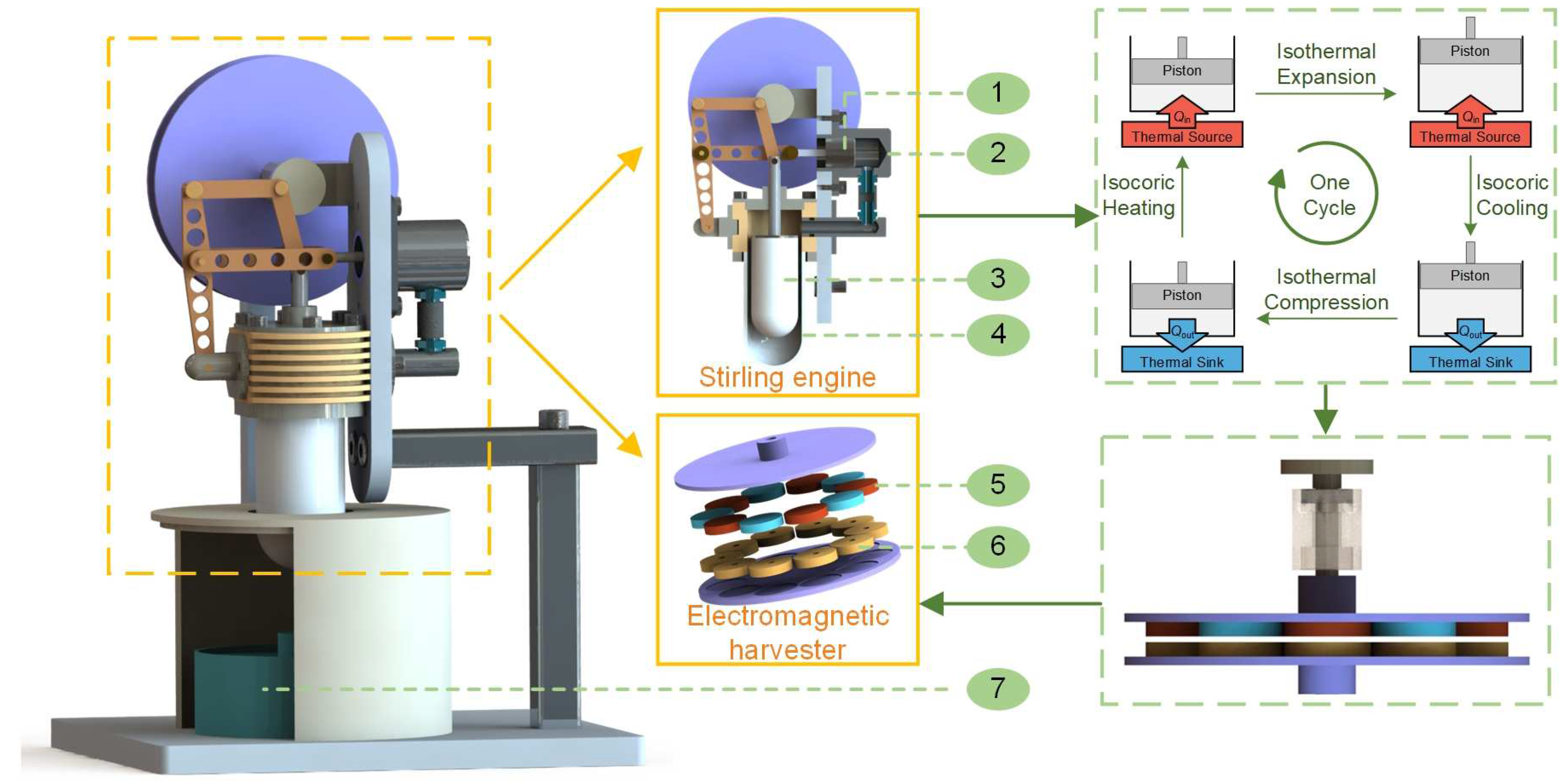
2. Design and Working Principle

The AFEEH-SE consists of two primary components: a Stirling engine and an electromagnetic energy harvester, as shown in Figure 1. The former converts thermal energy into mechanical energy, while the latter converts mechanical energy into electric energy.
The Stirling engine functions based on the Stirling cycle, incorporating four fundamental processes: isothermal expansion, isochoric cooling, isothermal compression, and isochoric heating. During isothermal expansion, the gas in the hot chamber absorbs heat, maintaining a constant temperature while expanding and working on the piston. Following this, during isochoric cooling, the gas transfers to the cooler part of the engine without changing its volume, but it releases heat and decreases in temperature. In the isothermal compression phase, the gas is compressed at a constant temperature, giving off heat in the process. Finally, during isochoric heating, the gas increases in temperature while maintaining constant volume as it returns to the hot chamber, completing the cycle. A gamma-type Stirling engine with a slider-crank structure is selected. Its main components include a gas distribution piston and a power piston. The gas distribution piston operates in the hot chamber, where the temperature generally exceeds 400 °C, enduring significant temperature gradients and slight pressure variations. To optimize thermal conductivity, high-temperature-resistant quartz glass is employed for the gas distribution piston, designed with a hollow thin-walled structure to minimize heat loss. The power piston is in direct contact with the cold chamber, facilitating the expansion and compression of the working gas. To ensure minimal resistance and prevent gas leakage, the power piston is made of high-temperature-resistant 310S stainless steel, with a clearance fit established between the piston and the inner chamber wall. The heat source is provided by the combustion of mineral oil and is placed at the lower end of the Stirling engine’s hot chamber. The slider-crank structure serves to convert the vertical and horizontal reciprocating motion of the pistons into rotational mechanical energy, achieving the conversion from thermal to mechanical energy.
The harvester comprises a rotating magnet array and a stationary coil array. Evenly spaced circular magnets, with alternating magnetic poles, are distributed uniformly on the rotating disk. The coil array consists of coils connected in series, matching the number of magnets to maximize power output. The magnets and coils are uniformly distributed in the grooves of the rotating and stationary disks, respectively. The rotating disc is mechanically connected to the rotor of the Stirling engine through a connecting shaft, thereby regulating the conversion of mechanical energy into electrical energy.
EMEHs convert ambient mechanical energy into electricity via Faraday’s Law of Induction: when a conductor coil moves relative to a magnetic field, the changing magnetic flux induces a voltage proportional to the motion speed and field strength. This induced electromotive force drives current through the coil, enabling energy extraction from otherwise wasted mechanical sources. Figure 2 shows in detail the working principle of the harvester proposed in this paper. The distribution of a magnet array consisting of ten magnets is displayed on the left side. Assuming the rotor rotates clockwise at a speed of n (rpm) and the initial center of the coil is located at point a. After the rotor rotates θT, the center of the coil shifts to point b. The induced voltage in the coil can be calculated using the following equation [41]:
ε = N d Φ B d t = N d Φ B d θ d θ d t
where ε is the induced voltage, N is the number of turns in each coil, ΦΒ is the magnetic flux, and θ and t represent the rotation angle and time, respectively.
The operational status of the coil during this process is depicted on the right side. The magnetic field distribution was calculated by Comsol 6.0. In the initial state, the magnet is aligned with the coil and no current flows through the coil under the positive magnetic field. When the rotor rotates by angle θT/4, the coil is positioned between two neighboring magnets and the magnetic flux through the coil decreases, inducing a positive current (process Ⅰ). As the rotor continues to rotate by angle θT/4, a negative magnetic field appears in the coil (process Ⅱ). When the rotor rotates by angle θT/4 again, the negative magnetic field weakens and a reverse current is induced in the coil (process Ⅲ). Finally, as the rotor continues to rotate by angle θT/4, it reaches a new state identical to the initial state (process Ⅳ). The magnetic flux through the coil and the induced voltage during the above operation are shown in the center of Figure 2. The working frequency of the harvester can be expressed as:
f = 360 θ T n 60 = N P 2 n 60 = n N P 120
where NP is the number of magnet-coil pairs and n is the rotational speed of the rotor. The voltage generated by the coil array is the superposition of the voltages generated by individual coils.

3. Results and Discussion

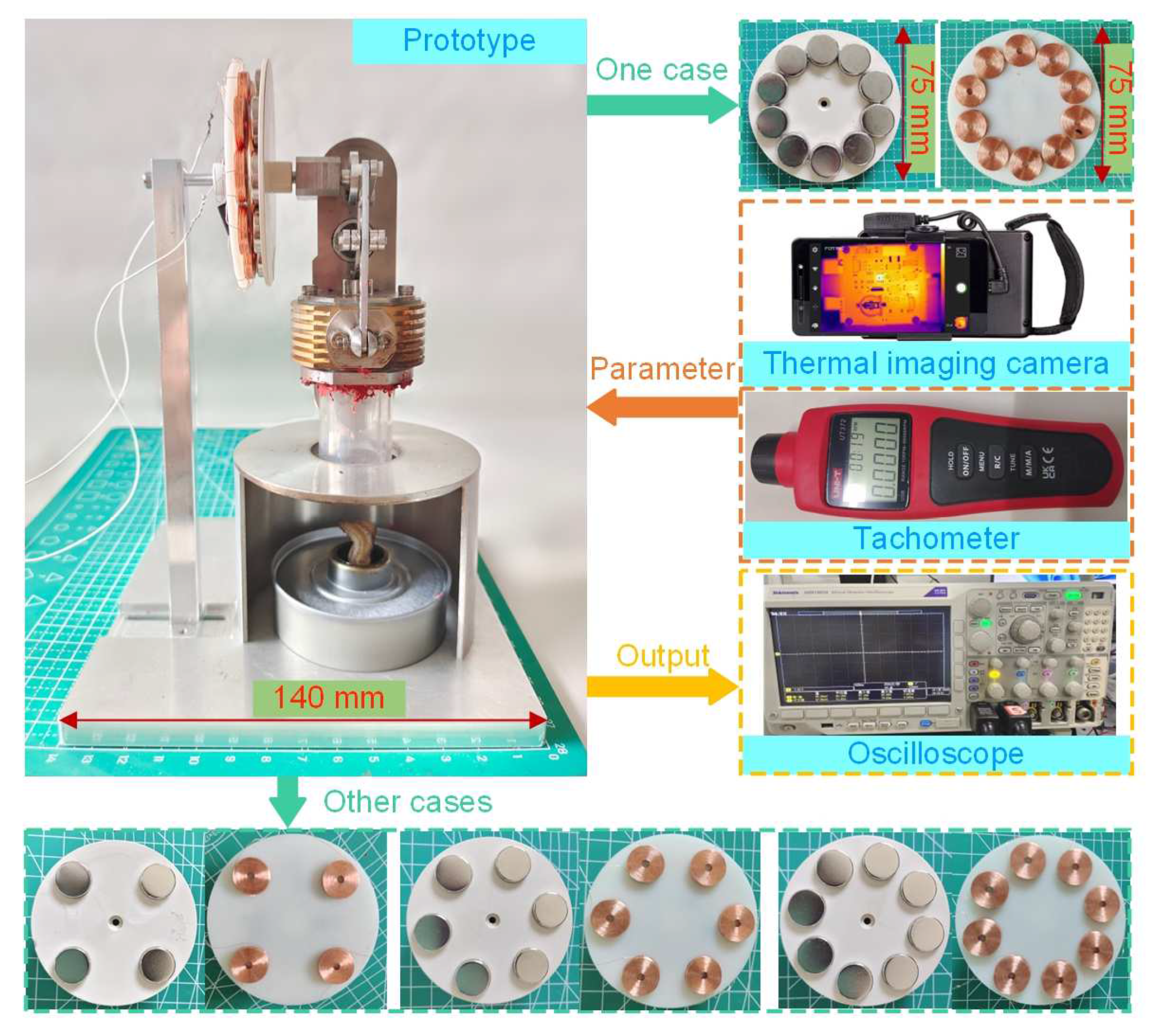
3.1. Experimental Setup and Prototype

To evaluate the performance of the harvester shown in Figure 1, a prototype was fabricated and comparative experiments were conducted using various magnet and coil arrays. The experimental setup is shown in Figure 3 and the main component parameters are detailed in Table 1. Aluminum alloy is employed to fabricate the base and support to facilitate prototype fixation. The Stirling engine is mounted on the support and mineral oil is located below the Stirling engine to provide the required heat source for the experiment by heating the hot chamber. To concentrate heat and ensure effective insulation, a partially enclosed thermal shield made of aluminum alloy is added between the Stirling engine and the heat source. The magnet array consists of N52-grade neodymium magnets (manufactured by Xinyongquan Magnetics in Dongguan, China), known for their high magnetic strength and stability. These magnets are mounted on a magnet rotor, which is connected to the Stirling engine rotor through a coupling structure. The coil array (manufactured by Yuehao Electronics in Foshan, China) is embedded in the grooves of the coil disc and affixed to a removable support. Both the magnet disc and coil disc are made of Polyphenylene sulfide, ensuring excellent thermal stability. An infrared camera (Fotric 226, manufactured by FOTRIC in Shanghai, China) is placed on a triangular stand 50 cm away from the prototype to monitor the temperatures of the hot and cold chambers in real time during prototype operation. A tachometer (UT371, manufactured by UNI-T in Dongguan, China) is employed to record the rotational speed of the magnet rotor. The voltage response of the prototype is measured by an oscilloscope (Tektronix MDO3024, manufactured by Tektronix, Beaverton, OR, USA).

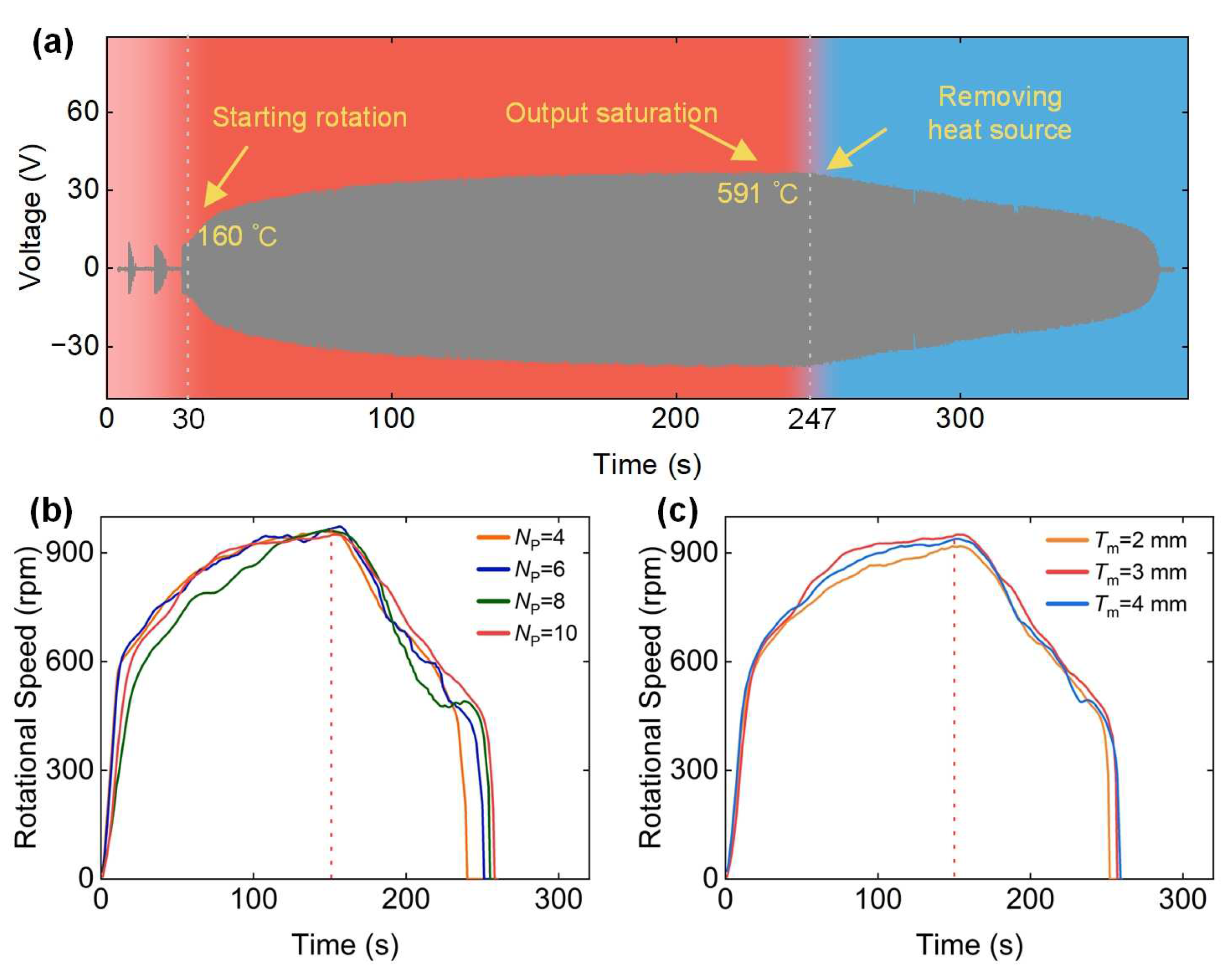
3.2. Rotational Speed for Different Magnet Arrays

An initial excitation is required for the Stirling engine to start rotating. In the experiments, a finger tap on the disc was used as the initial excitation. Figure 4 displays the infrared temperature images at three critical stages: before starting, during the beginning of rotation, and at stable operation. The temperature measurement regions of the hot and cold chambers are highlighted in the images with red and blue boxes, respectively. Figure 5a illustrates the voltage output of the AFEEH-SE throughout the entire motion process. The engine starts operating 30 s after the initial excitation is applied, at which point the hot chamber temperature is 160 °C. A peak voltage is reached at approximately 170 s, with the hot chamber temperature maintained at 591 °C. After removing the heat source, the air temperature inside the Stirling engine gradually decreases. The sealed structure of the Stirling engine chamber allows it to continue operating for 120 s.
To assess the impact of magnet parameters on the prototype performance, two sets of rotational speed experiments were conducted. In the first set, the number of magnets was varied while the magnet thickness was fixed at 3 mm. In the second set, the number of magnets was fixed at 10 and the magnet thickness was varied. Before each measurement, the prototype was cooled until both the hot and cold chambers reached the ambient temperature (25 °C). The heat source was removed 150 s after the prototype started rotating.
Figure 5b illustrates the motion of prototypes with different numbers of magnets. The rotational speed of the magnet discs for each prototype increases, stabilizes, and then decreases over time. During the continuous burning of mineral oil, the temperature of hot chamber rises rapidly, while the temperature of cold chamber changes slowly. The increasing temperature difference between the hot and cold chambers accelerates the piston motion of the Stirling engine, consequently boosting the disc speed. At 100 s, the disc speed approaches 900 rpm and eventually stabilizes at around 950 rpm. After 150 s, the disc speed begins to slow down due to the removal of the heat source. In all four cases, the speed increase trajectory during the heating phase is identical. However, the operation duration after removing the heat source is slightly different. The prototype with 4 magnets stops after operating for 89 s, while the prototype with 10 magnets has the longest operation duration of 107 s. This is attributed to the more uniform distribution of disc mass with a higher number of magnets, reducing the mechanical damping of the system.
The speed variation trends of prototypes with different magnet thicknesses in Figure 5c are similar to the case in Figure 5b. Compared to the number of magnets, the effect of magnet thickness on rotational speed is smaller, as evidenced by the greater overlap of the three curves. The highest speed, 950 rpm, is achieved when the magnet thickness is 3 mm. The operation durations after heat source removal are 101 s, 106 s, and 108 s, showing minor variations.

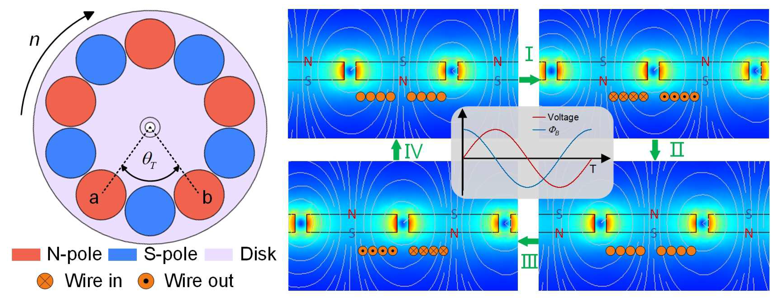
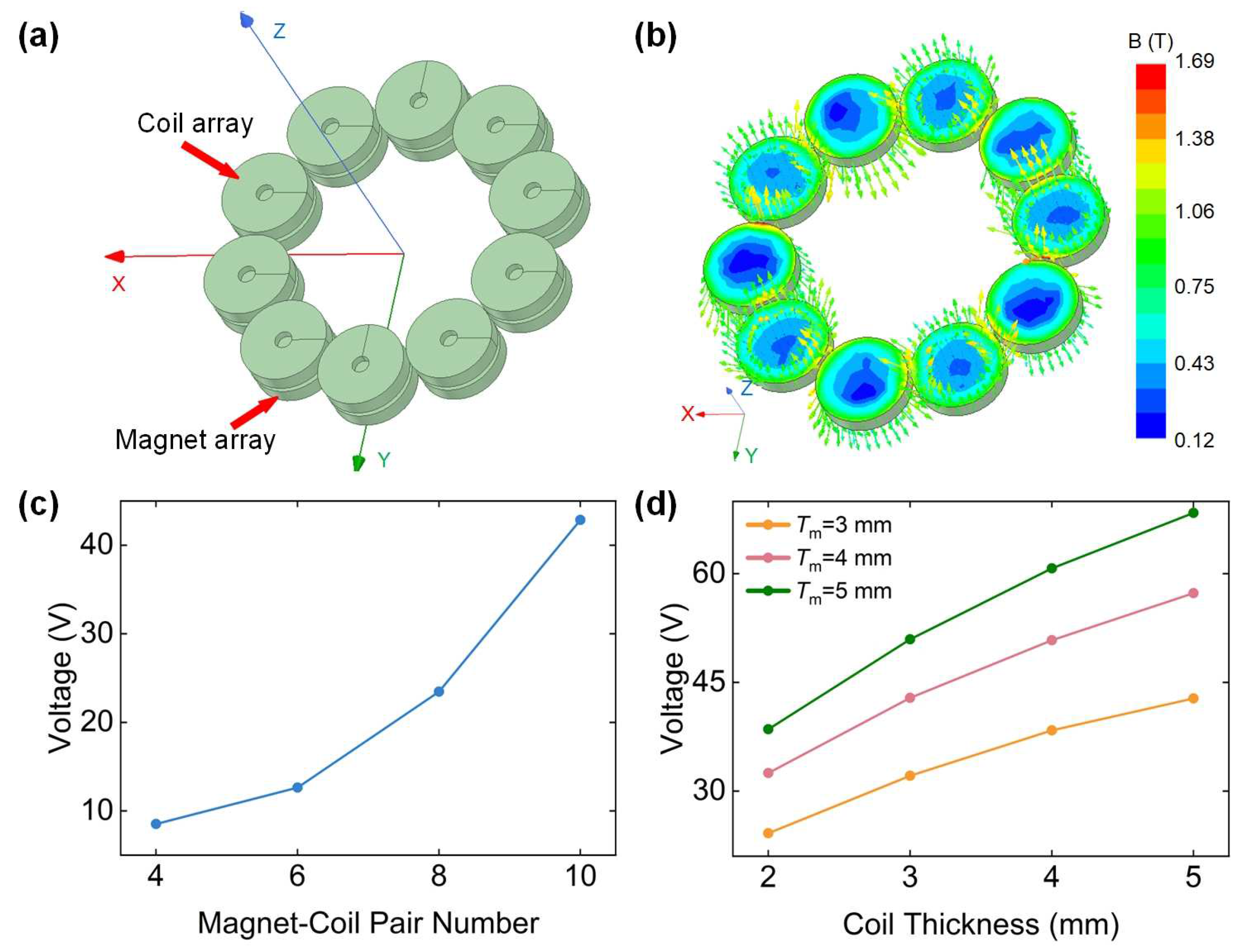
3.3. Simulation of Open-Circuit Voltage

To investigate the impact of magnet and coil parameters on the open-circuit voltage, Maxwell3D FEM simulations were conducted using ANSYS (version 19.2), as shown in Figure 6. The finite element model consists of alternately arranged magnets and series-connected coils. The magnetic flux (1 T) direction of adjacent magnets is opposite along the Z-axis of the coordinate system. The coil array is positioned on the top surface of the magnet array, as depicted in Figure 6a,b, showing the magnetic flux density (MFD) distribution on the surface of the magnet array, which is composed of ten 3 mm-thick magnets. The MFD reaches its maximum at the junction of adjacent magnets and the magnetic induction vector of adjacent magnets is opposite along the Z-axis.
In closed-loop electromagnetic systems, the damping force includes mechanical damping and electromagnetic damping. Mechanical damping of the prototype is minimized through the use of bearings and lubricating oil. Consequently, for simplification purposes in this study, mechanical damping is disregarded in the calculations. For electromagnetic damping, all models in the simulations are configured in an open-circuit state to obtain voltage for comparison. Therefore, electromagnetic damping is assumed to be negligible. The magnet array is set to rotate at a constant speed of 950 rpm (experimentally obtained rotational speed of Stirling engine during stable operation), while the coil array remains stationary, with the gap between them adjusted to 1 mm.
The effect of varying the number of magnet-coil pairs on the open-circuit voltage was initially evaluated, while the thickness of both magnets and coils was kept constant at 3 mm. As shown in Figure 6c, the voltage rises from 8.51 V to 42.85 V as the number of pairs increases. This phenomenon can be attributed to two factors. First, the increase in the number of magnets amplifies the magnetic flux change rate in each coil, thereby heightening the induced voltage in individual coils. Second, the increase in the number of coils leads to cumulative voltage growth across the coil array. Subsequently, with the number of magnet-coil pairs fixed at 10, the variation of voltage with respect to magnet and coil thickness was investigated. As depicted in Figure 6d, the voltage increases as the thickness of the magnets (Tm) rises. At the same rotational speed, thicker magnets exhibit higher MFD on their surfaces, resulting in an increase in B/dt, which consequently increases induced voltage according to Equation (1). Additionally, at the same magnet thickness, the induced voltage increases with the coil thickness (Tc) due to the corresponding increase in the number of coil turns.

3.4. Comparisons of Experimental Results

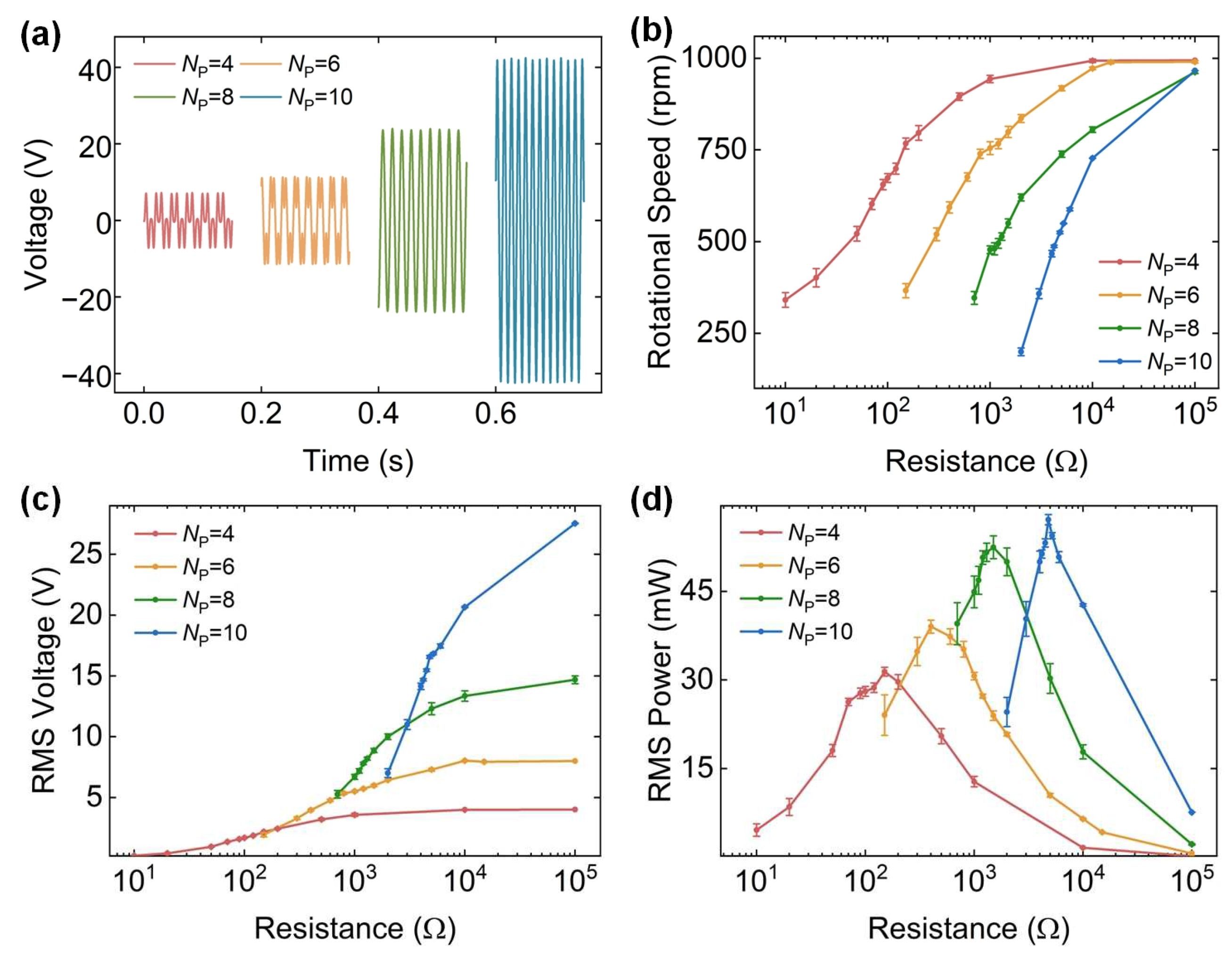
3.4.1. Prototype Performance for Different Numbers of Magnet-Coil Pairs

In this section, comparative experiments were conducted on the open-circuit voltage and output power of the prototypes with different numbers of magnet-coil pairs. The coils and magnets utilized in the experiments had a thickness of 3 mm. To ensure the reliability of the data, all comparison experiments were repeated three times. In this paper, the power calculation employs the root mean square (RMS) method, which is expressed as follows:
P RMS = V RMS 2 R load
where VRMS and Rload represent the RMS voltage and the resistance at the load terminal, respectively. For experimentally measured discrete data, the VRMS can be calculated as:
V RMS = 1 N i = 1 N v i 2
where vi is the voltage measurement at the i-th position and N is the total number of measurements. Since MATLAB has a dedicated function for calculating the RMS, we use the rms function in MATLAB (R2021a) to determine the VRMS. Neglecting the impact of electromagnetic damping, the maximum power point arises when the load resistance matches the coil resistance. However, the rotational speed of the prototype is affected under different loads due to the influence of electromagnetic damping. Therefore, the actual maximum power point requires verification through impedance matching experiments.
Figure 7a illustrates the open-circuit voltage of prototypes with different numbers of magnet-coil pairs during stable operation. The voltage in all four cases is a stable continuous signal, and its amplitude increases with the number of magnet-coil pairs. The average peak voltages are 7.21 V, 12.65 V, 22.24 V, and 42.28 V. The voltage frequency is proportional to the number, confirming the theoretical prediction of Equation (2). At a rotational speed of 950 rpm, the experimental results are consistent with the simulation results (8.51 V for NP = 4, 12.63 V for NP = 6, 23.46 V for NP = 8, and 42.85 V for NP = 10). Subsequently, experiments under different loads were conducted on the four cases.
Figure 7b,c presents the rotational speeds of the disc and the voltage outputs in the load spectrum in the four cases. As the load increases, both the rotational speed and voltage output exhibit an increasing trend. For NP = 4 and NP = 6, the rotational speed and voltage output approach saturation when the load exceeds 10 kΩ, equivalent to an open-circuit condition for the prototype. For NP = 8 and NP = 10, larger loads are required to achieve saturation of the speed and voltage output. This is because, under the same load, a greater number of coils and magnets in the prototype generate a higher current, resulting in a larger electromagnetic damping force. Furthermore, the starting loads corresponding to different numbers of magnet-coil pairs are 10 Ω, 150 Ω, 700 Ω, and 2000 Ω, respectively, which indicates that the starting process becomes more difficult as the number of magnets increases.
As the load increases, the power output in four cases demonstrates an initial rise followed by a subsequent decline, as shown in Figure 7d. As the number of magnet-coil pairs increases, both the maximum output power and the corresponding resistance increase. The prototype with NP = 10 has a maximum power output of 57.13 mW under a load resistance of 4800 Ω, indicating optimal performance.

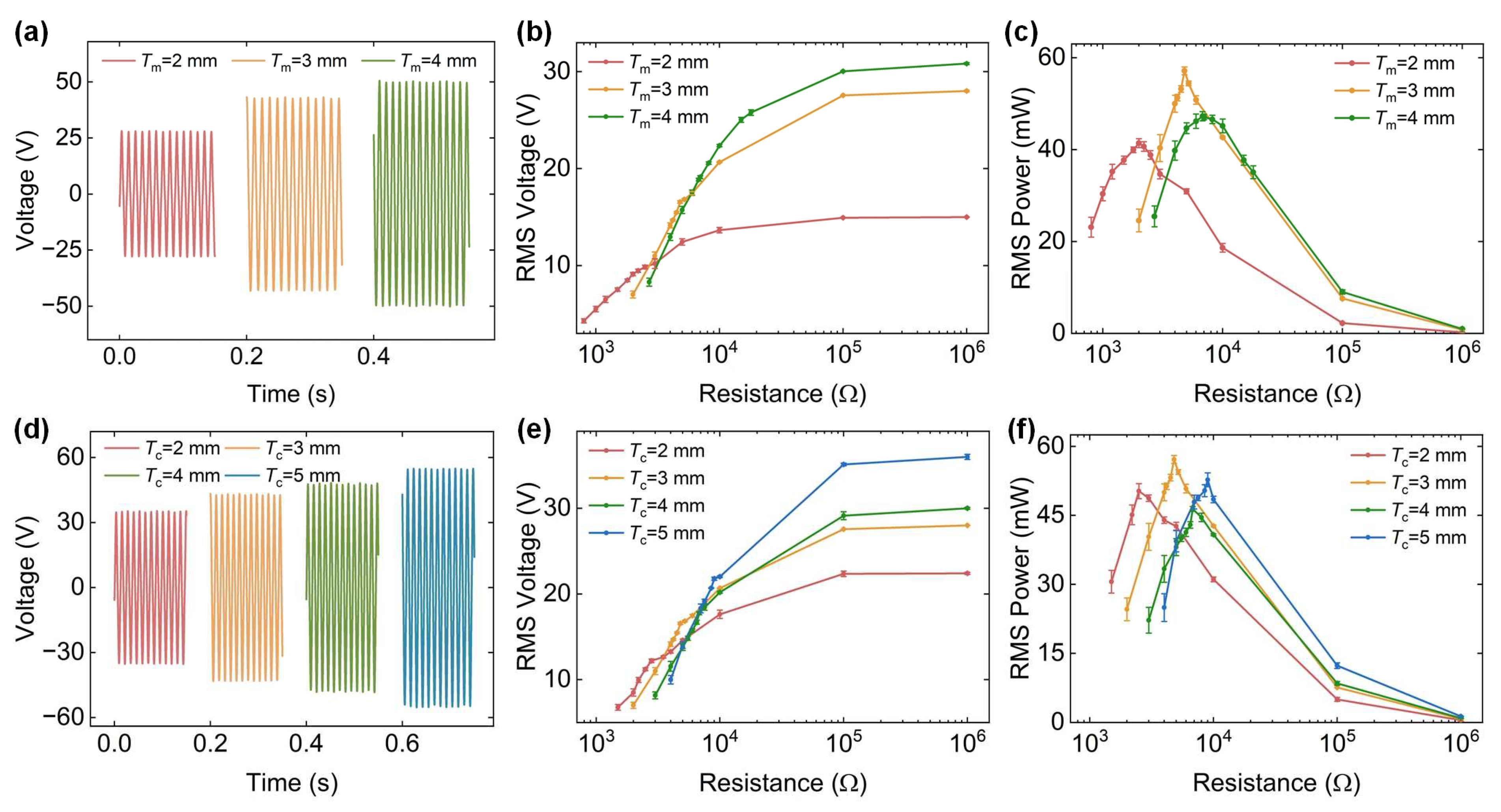
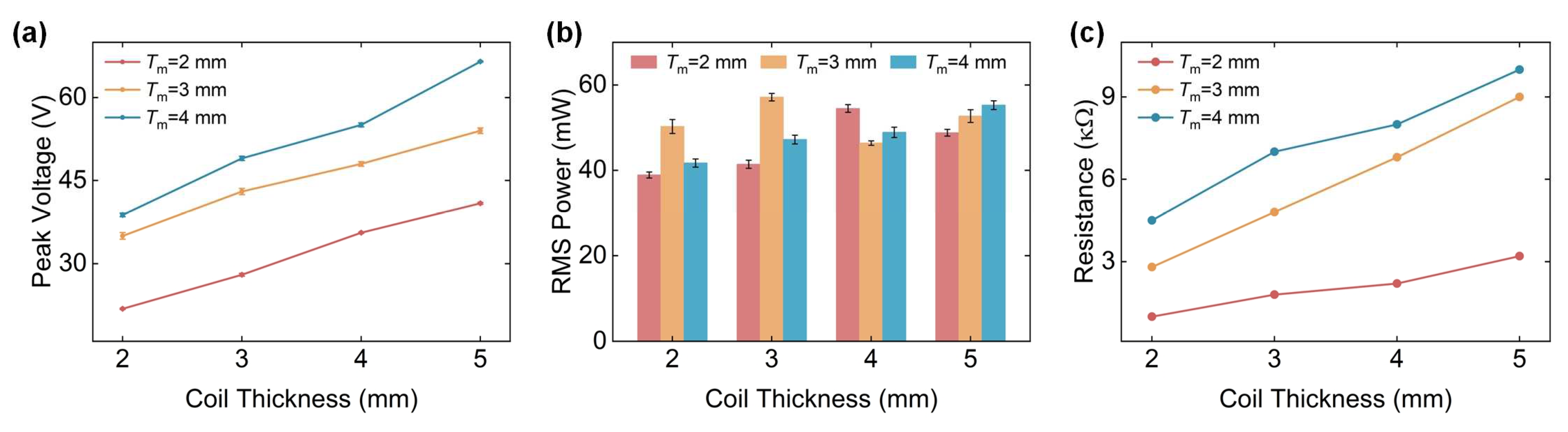
3.4.2. Prototype Performance for Different Thicknesses of Magnets and Coils

In this section, combination experiments were conducted with magnets and coils of different thicknesses, comparing the open-circuit voltage and power output of the prototype under different combinations. The magnet-coil pair was set to 10, with magnet thicknesses of 2 mm, 3 mm, and 4 mm and coil thicknesses of 2 mm, 3 mm, 4 mm, and 5 mm.
Figure 8a–c compares the performance of prototypes with different magnet thicknesses while keeping the coil thickness constant at 3 mm. Under open circuit conditions, the voltage output increases with magnet thickness as shown in Figure 8a, which is consistent with the simulation results. Figure 8b,c shows the voltage and power output over the load spectrum for different magnet thicknesses. As the magnet thickness increases, the resistance when the disk first begins to rotate also increases, suggesting a greater difficulty in starting with thicker magnets. The power curves for the three cases follow the same trend, reaching peak power output under different loads. The prototype with a magnet thickness of 3 mm exhibits the highest power output.
Subsequently, the magnet thickness was maintained at the optimal value of 3 mm and the coil thickness was varied to study its effect on the performance of the prototype. The open-circuit voltages for coil thicknesses of 2 mm, 3 mm, 4 mm, and 5 mm are 34.16 V, 43.08 V, 47.90 V, and 54.88 V, respectively, as shown in Figure 8d. With increasing coil thickness, the open-circuit voltage demonstrates an ascending trend. Figure 8e,f represents the voltage and power output over the load spectrum for different coil thicknesses. The voltage and power outputs follow a similar trend to that of the magnet array, with the maximum power point observed at Tc = 3 mm.
To further determine the optimal combination for performance improvement, supplementary experiments were conducted on additional magnet and coil combinations. Figure 9a depicts the open-circuit voltages for different combinations. The acquired voltage is close to the simulation results, with deviations primarily caused by fluctuations in the rotational speed of the prototypes. Figure 9b,c illustrates the maximum PRMS output and corresponding load for various combinations. As the thickness of the magnets and coils increases, the load at the maximum power point also shows an upward trend. Through comprehensive comparison, the combination of 3 mm magnets and 3 mm coils achieves the highest power output, reaching 57.13 mW with a corresponding load of 4800 Ω.
The efficiency of the AFEEH-SE in converting thermal energy into electrical energy is calculated using the following equation:
η = P out Q in × 100 %
where Pout represents the average output power and Qin denotes the heat power, which corresponds to the amount of heat transferred per unit time. Since the output power of the prototype in the optimal configuration has been calculated above, Pout = PRMS = 57.13 mW.
The heat power is calculated as:
Q in = h A T s T amb
where h is the convective heat transfer coefficient, taken as 10 W/m2K [42], A is the effective heat transfer area, corresponding to the outer surface area of the hot chamber (37.3 cm2), Ts is the surface temperature of the hot chamber (591 °C), and Tamb is the ambient temperature (25 °C). Based on these values, the heat power is calculated to be 21.1 W. Consequently, the thermal-to-electrical conversion efficiency of the system is determined to be 0.27%.
The output performance of the harvester developed in this paper was then compared with that of harvesters from similar studies, as shown in Table 2. The data reveal that this harvester achieved an average output power of 57.13 mW, the highest among the units compared, demonstrating its superior capability for waste heat recovery applications.

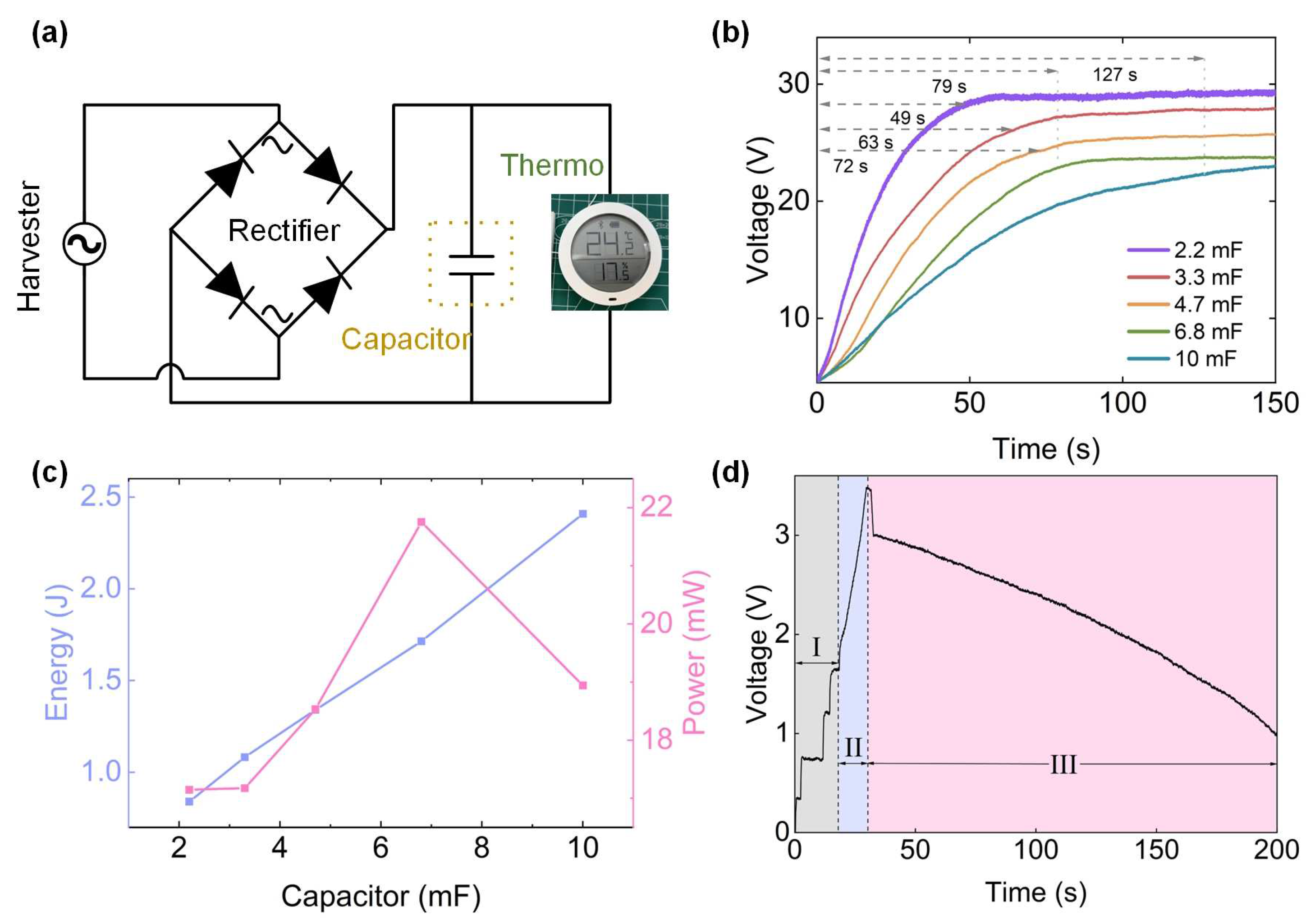
3.5. Performance for Capacitor Charging

The charging performance of the prototype under the aforementioned optimal configuration was investigated. The experimental circuit, shown in Figure 10a, consists of a prototype, a rectifier for converting AC to DC, a capacitor, and a thermometer.
First, the prototype’s ability to charge capacitors was verified. Five millifarad (mF)-level capacitors with capacities of 2.2 mF, 3.3 mF, 4.8 mF, 6.8 mF, and 10 mF were selected, each rated at 25 V. All capacitors were fully discharged prior to the experiment and their voltage changes during charging were recorded. Since the capacitors were initially fully discharged, the circuit exhibited an approximate short-circuit state at the start, requiring the prototype to undergo a manual startup phase. To better analyze the charging performance, the focus was placed on the stable charging phase, which begins when the capacitor voltage exceeds 4.5 V. As shown in Figure 10b, the capacitors exhibit rapid growth in the initial phase, followed by gradual deceleration. The charging times for the five capacitors are 49 s, 63 s, 72 s, 79 s, and 127 s, with concluding voltages of 28 V, 26 V, 24 V, 23 V, and 22 V, respectively. The results indicate that as the capacitor capacity increases, the charging time significantly extends.
To analyze the charging experiments from the perspectives of energy and power, Joule’s law is invoked. The total charging energy E of a capacitor is:
E = C P U 2 U 0 2 2
where CP, U, and U0 are the capacitance, ending voltage, and starting voltage of the capacitor, respectively. In addition, the average charging power P is:
P = E t
where t is the capacitor charging time. Figure 10c illustrates the charging energy and power of different capacitors. As the capacitor capacity increases, the energy required for full charging gradually rises. It is noteworthy that the 6.8 mF capacitor exhibits the maximum charging power, reaching 21.75 mW. Smaller capacitors take less time to reach higher voltages. However, larger capacitors can store more energy, which is crucial for powering electronic devices.
Subsequently, a 6.8 mF capacitor was selected to power the thermometer, with its power terminals connected directly across the capacitor after battery removal. The charging process is shown in Figure 10d. The voltage response during capacitor charging can be divided into three stages. The first stage is the prototype startup phase. The prototype begins to operate when the capacitor voltage rises to 1.68 V. The second stage is the stable charging phase, during which the capacitor continues charging until it reaches 3.5 V, at which point the thermometer is connected to the circuit. The third stage is the thermometer operation phase. Upon connection, the capacitor voltage drops by 0.5 V, successfully charging the thermometer and enabling it to start operating. After 167 s of continuous operation, the capacitor voltage drops to the thermometer’s minimum startup voltage of 1 V, causing the thermometer to shut down.
The experimental results confirm that the designed prototype can provide continuous power to sensors and demonstrate its great potential beyond its current application scope.

4. Conclusions

In summary, this study successfully designed and fabricated an axial flux electromagnetic energy harvester driven by a Stirling engine. The gamma-type Stirling engine designed for this purpose effectively converted waste heat into mechanical energy, which was then transformed into electrical energy through electromagnetic induction. This research innovatively considered electromagnetic damping, examining the influence of magnet and coil parameters on the energy harvester’s output. Through a series of comparative experiments, the optimal configuration was determined. When using mineral oil as the heat source, the prototype achieved an open-circuit rotational speed of 950 rpm. Under optimal configurations, it generated an open-circuit voltage of 42.85 V and an effective power output of 57.13 mW, achieving a thermoelectric conversion efficiency of 0.27%. Considering these results, the proposed AFEEH-SE system becomes a strong candidate for the next generation of efficient thermal energy harvesting technologies. Future research will delve into the effects of impedance characteristics on system performance and seek to optimize the design for enhanced practical application.

Author Contributions

Conceptualization, Z.L.; writing—original draft preparation, L.Z.; writing—review and editing, Y.G. and F.S.; resources, Y.P.; supervision, H.W. All authors have read and agreed to the published version of the manuscript.

Funding

This research was funded by National Natural Science Foundation of China (No.: 62473246), National Natural Science Foundation of China (No.: 62225308), and Shanghai Science and Technology Committee (No.: 22dz1204300).

Data Availability Statement

The original contributions presented in this study are included in the article. Further inquiries can be directed to the corresponding author.

Conflicts of Interest

The authors declare no conflicts of interest.

Abbreviations

The following abbreviations are used in this manuscript:
AFEEH-SEAxial flux electromagnetic energy harvester driven by a Stirling engine
PZTsPiezoelectric nanogenerators
EMEHsElectromagnetic energy harvesters
TENGsTriboelectric nanogenerators
MFDMagnetic flux density

References

  1. Jouhara, H.; Żabnieńska-Góra, A.; Khordehgah, N.; Ahmad, D.; Lipinski, T. Latent thermal energy storage technologies and applications: A review. Int. J. Thermofluids 2020, 5, 100039. [Google Scholar] [CrossRef]
  2. Sadeghi, G. Energy storage on demand: Thermal energy storage development, materials, design, and integration challenges. Energy Storage Mater. 2022, 46, 192–222. [Google Scholar] [CrossRef]
  3. Wu, M.; Wu, S.; Cai, Y.; Wang, R.; Li, T. Form-stable phase change composites: Preparation, performance, and applications for thermal energy conversion, storage and management. Energy Storage Mater. 2021, 42, 380–417. [Google Scholar] [CrossRef]
  4. Zuo, L.; Tang, X. Large-scale vibration energy harvesting. J. Intell. Mater. Syst. Struct. 2013, 24, 1405–1430. [Google Scholar] [CrossRef]
  5. Miraglia, M.; Tannous, M.; Inglese, F.; Brämer, B.; Milazzo, M.; Stefanini, C. Energy recovery from shock absorbers through a novel compact electro-hydraulic system architecture. Mechatronics 2022, 81, 102701. [Google Scholar] [CrossRef]
  6. Liu, H.; Lim, C.W.; Gao, S.; Zhao, J. Effects analysis of bias and excitation conditions on power output of an environmental vibration energy harvesting device using Fe-Ga slice. Mechatronics 2019, 57, 20–28. [Google Scholar] [CrossRef]
  7. Kan, J.; Lin, S.; Wang, J.; Wang, K.; Gu, Y.; Wang, S.; Meng, F.; Zhang, Z. Design, fabrication and characterization of a wind-isolated galloping energy harvester via an embedded piezoelectric transducer. Mechatronics 2024, 99, 103147. [Google Scholar] [CrossRef]
  8. Shi, B.; Wang, Q.; Su, H.; Li, J.; Xie, B.; Wang, P.; Qiu, J.; Wu, C.; Zhang, Y.; Zhou, X. Progress in recent research on the design and use of triboelectric nanogenerators for harvesting wind energy. Nano Energy 2023, 116, 108789. [Google Scholar] [CrossRef]
  9. Liu, F.R.; Zhao, L.C.; Yan, G.; Zhang, W.M.; Wu, Z.Y.; Zhang, X.L. Performing Magnetic Boundary Modulation to Broaden the Operational Wind Speed Range of a Piezoelectric Cantilever-Type Wind Energy Harvester. Micromachines 2024, 15, 1286. [Google Scholar] [CrossRef]
  10. Lin, Y.; Chong, C.H.; Ma, L.; Li, Z.; Ni, W. Quantification of waste heat potential in China: A top-down Societal Waste Heat Accounting Model. Energy 2022, 261, 125194. [Google Scholar] [CrossRef]
  11. Xiao, Y.; Zhang, Y.; Wang, J.; Liu, W.; Wan, F. Research on the Robustness of the Roots Waste Heat Power Generation System. IEEE Access 2021, 9, 155103–155112. [Google Scholar] [CrossRef]
  12. Xu, Z.Y.; Wang, R.Z.; Yang, C. Perspectives for low-temperature waste heat recovery. Energy 2019, 176, 1037–1043. [Google Scholar] [CrossRef]
  13. Shchegolkov, A.; Komarov, F.; Lipkin, M.; Milchanin, O.; Parfimovich, I.; Shchegolkov, A.; Semenkova, A.; Velichko, A.; Chebotov, K.; Nokhaeva, V. Synthesis and study of cathode materials based on carbon nanotubes for lithium-ion batteries. Inorg. Mater. Appl. Res. 2021, 12, 1281–1287. [Google Scholar]
  14. Gong, S.; Li, X.; Sheng, M.; Liu, S.; Zheng, Y.; Wu, H.; Lu, X.; Qu, J. High thermal conductivity and mechanical strength phase change composite with double supporting skeletons for industrial waste heat recovery. ACS Appl. Mater. Interfaces 2021, 13, 47174–47184. [Google Scholar]
  15. Michel, B.; Dufour, N.; Börtlein, C.; Zoude, C.; Prud’Homme, E.; Gremillard, L.; Clausse, M. First experimental characterization of CaCl2 coated heat exchanger for thermochemical heat transformer applications in industrial waste heat recovery. Appl. Therm. Eng. 2023, 227, 120400. [Google Scholar]
  16. Kim, Y.; Mehmood, M.U.; Han, H.J.; Kim, Y.J.; Oh, S.J.; Lim, S.-H. Reclaiming Power Potential from Low Temperature Waste Heat by Thermomagnetic Heat Engines. Energies 2022, 15, 2817. [Google Scholar] [CrossRef]
  17. Thombare, D.; Verma, S. Technological development in the Stirling cycle engines. Renew. Sustain. Energy Rev. 2008, 12, 1–38. [Google Scholar]
  18. Zare, S.; Tavakolpour-Saleh, A. Free piston Stirling engines: A review. Int. J. Energy Res. 2020, 44, 5039–5070. [Google Scholar]
  19. Walker, G.; Fauvel, R.; Gustafson, R.; Van Bentham, J. Stirling engine heat pumps. Int. J. Refrig. 1982, 5, 91–97. [Google Scholar]
  20. Ahmed, F.; Huang, H.; Ahmed, S.; Wang, X. A comprehensive review on modeling and performance optimization of Stirling engine. Int. J. Energy Res. 2020, 44, 6098–6127. [Google Scholar]
  21. Arif, H.; Shah, A.; Ratlamwala, T.A.H.; Kamal, K.; Khan, M.A. Effect of material change on Stirnol engine: A combination of NiTiNOL (shape memory alloy) and gamma Stirling engine. Materials 2023, 16, 3257. [Google Scholar] [CrossRef] [PubMed]
  22. Li, J.Q.; Wang, F.P. Numerical investigations on the Stirling engine power and the efficiency of Stirling engine generator. Adv. Mech. Eng. 2022, 14, 16878132221117017. [Google Scholar] [CrossRef]
  23. Yu, X.; She, C.; Gholizadeh, F.; Xu, Y.-P. Numerical investigation of a new combined energy cycle based on Miller cycle, Organic Rankine cycle, Stirling engine and alkaline fuel cell. Energy Rep. 2021, 7, 5406–5419. [Google Scholar] [CrossRef]
  24. Ahmadi, M.H.; Ahmadi, M.A.; Pourfayaz, F.; Hosseinzade, H.; Acıkkalp, E.; Tlili, I.; Feidt, M. Designing a powered combined Otto and Stirling cycle power plant through multi-objective optimization approach. Renew. Sustain. Energy Rev. 2016, 62, 585–595. [Google Scholar] [CrossRef]
  25. Entezari, A.; Manizadeh, A.; Ahmadi, R. Energetical, exergetical and economical optimization analysis of combined power generation system of gas turbine and Stirling engine. Energ Convers Manag. 2018, 159, 189–203. [Google Scholar] [CrossRef]
  26. Chapman, J.W.; Simon, D.L.; McNichols, E. An Analysis of the Strayton Engine, a Brayton and Stirling Cycle Recuperating Engine. In Proceedings of the AIAA Propulsion and Energy 2019 Forum, Indianapolis, IN, USA, 19–22 August 2019. [Google Scholar]
  27. Tavares, R.; Ruderman, M. Energy harvesting using piezoelectric transducers for suspension systems. Mechatronics 2020, 65, 102294. [Google Scholar] [CrossRef]
  28. Wu, Z.Y.; Wu, Z.H.; Chen, I.M.; Xu, Q.S. Recent Advances in Piezoelectric Compliant Devices for Ultrahigh-Precision Engineering. Micromachines 2024, 15, 1456. [Google Scholar] [CrossRef]
  29. Pasharavesh, A.; Moheimani, R.; Dalir, H. Performance Analysis of an Electromagnetically Coupled Piezoelectric Energy Scavenger. Energies 2020, 13, 845. [Google Scholar] [CrossRef]
  30. Miao, G.; Fang, S.; Wang, S.; Zhou, S. A low-frequency rotational electromagnetic energy harvester using a magnetic plucking mechanism. Appl. Energy 2022, 305, 117838. [Google Scholar] [CrossRef]
  31. Zhao, L.; Hu, G.; Zhou, S.; Peng, Y.; Xie, S.; Li, Z. Magnetic coupling and amplitude truncation based bistable energy harvester. Int. J. Mech. Sci. 2024, 273, 109228. [Google Scholar] [CrossRef]
  32. Soares, I.N.; Altafim, R.A.C.; Altafim, R.A.P.; Moreira, M.d.M.A.C.; Sousa, F.S.I.d.; Afonso, J.A.; Carmo, J.P.; Flauzino, R.d.A. Investigation of a Magnetic Levitation Architecture with a Ferrite Core for Energy Harvesting. Energies 2024, 17, 5315. [Google Scholar] [CrossRef]
  33. Jiao, P.; Wang, Z.L.; Alavi, A.H. Maximizing Triboelectric Nanogenerators by Physics-Informed AI Inverse Design. Adv. Mater. 2024, 36, e2308505. [Google Scholar] [CrossRef] [PubMed]
  34. Peng, Y.; Liu, H.; Guo, H.; Gong, Y.; Shen, F.; Zhang, Q.; Li, Z. Toward Highly Sensitive Ocean-Wave Monitoring With Sliding-Triboelectric Effect: Modeling, Experimental Validation, and Demonstration. IEEE/ASME Trans. Mechatron. 2024, 29, 4630–4639. [Google Scholar] [CrossRef]
  35. Zheng, Q.; Xin, L.; Zhang, Q.; Shen, F.; Lu, X.; Cao, C.; Xin, C.; Zhao, Y.; Liu, H.; Peng, Y. Leech-Inspired Amphibious Soft Robot Driven by High-Voltage Triboelectricity. Adv. Mater. 2025, 37, 2417380. [Google Scholar]
  36. Formosa, F.; Badel, A.; Arroyo, E. Electromagnetic generator design for membrane micro Stirling engine. Power MEMS 2010 2010, 1–4. Available online: https://www.researchgate.net/publication/267687913 (accessed on 18 March 2025).
  37. Yun, J.; Kim, I.; Kim, D. Hybrid energy harvesting system based on Stirling engine towards next-generation heat recovery system in industrial fields. Nano Energy 2021, 90, 106508. [Google Scholar] [CrossRef]
  38. Shaislamov, U.; Kim, Y.; Kim, W.S.; Jeong, H.; Lee, H.J.; Chun, W. Hybrid operation of triboelectric nanogenerator for electricity generation by a low-temperature differential heat engine. Int. J. Energy Res. 2017, 41, 1412–1421. [Google Scholar]
  39. Panigrahi, B.K.; Ahmed, R.; Mehmood, M.U.; Park, J.C.; Kim, Y.; Chun, W. Operation of a low-temperature differential heat engine for power generation via hybrid nanogenerators. Appl. Energy 2021, 285, 116385. [Google Scholar]
  40. Stolyarov, S.P.; Stolayrov, A.S. Stirling Generators: Challenges and Opportunities. Russ. Electr. Eng. 2018, 88, 778–782. [Google Scholar] [CrossRef]
  41. Zhang, Q.; Kim, E.S. Vibration energy harvesting based on magnet and coil arrays for watt-level handheld power source. Proc. IEEE 2014, 102, 1747–1761. [Google Scholar]
  42. Hou, G.; Gao, L.; Qin, Y. Two-Temperature Approximation Analyzing the Combustion Characteristics of Premixed Gas-Air Mixture in Inert Porous Media. In Proceedings of the 2010 The Second China Energy Scientist Forum, Xuzhou, China, 18–19 October 2010. [Google Scholar]
  43. Zeeshan, A.R.; Chun, W.; Oh, S.; Kim, Y. Power generation from a hybrid generator (teng-emg) run by a thermomagnetic engine harnessing low temperature waste heat. Energies 2019, 12, 1774. [Google Scholar] [CrossRef]
Figure 1. Structural configuration and schematic diagram of the AFEEH-SE. The key components are labeled: (1) the power piston of the Stirling engine; (2) the cold chamber of the Stirling engine; (3) the gas distribution piston of the Stirling engine; (4) the hot chamber of the Stirling engine; (5) the magnet array; (6) the coil array; and (7) the heat source.
Energies 18 01620 g001
Figure 2. Schematic of the magnet array (left) and the induced voltage mechanism in a single coil during rotor-stator relative rotation (right). The red and blue circles represent the N-pole and S-pole of the magnets, respectively.
Energies 18 01620 g002
Figure 3. The prototype and experimental setup.
Energies 18 01620 g003
Figure 4. Infrared images of the Stirling engine at different operating stages. (a) Before starting; (b) starting rotation; and (c) output saturation. The red and blue boxes indicate the temperature measurement regions of the hot and cold chambers, respectively. The red △ and blue ▽ mark the highest and lowest temperature points within the selected regions.
Energies 18 01620 g004
Figure 5. Rotational speed characteristics of different magnet arrays. (a) Voltage output of the prototype at different stages. (b) Magnet disc rotational speed over time for different magnet numbers. (c) Magnet disc rotational speed over time for different magnet thicknesses.
Energies 18 01620 g005
Figure 6. Simulations of open-circuit voltage and MFD distribution. (a) The FEM model in Maxwell3D simulation. (b) MFD distribution of the magnet array. (c) Open-circuit voltage for different magnet-coil pair numbers. (d) Open-circuit voltage for different magnet and coil thicknesses.
Energies 18 01620 g006
Figure 7. Output performance of the prototypes with different magnet-coil pairs. (a) Open-circuit voltage. (b) Rotational speed over the load spectrum. (c) Voltage output over the load spectrum. (d) Power output over the load spectrum.
Energies 18 01620 g007
Figure 8. Output performance of the prototypes with different magnet and coil thicknesses. (ac) Voltage and power outputs with different magnet thicknesses. (df) Voltage and power outputs with different coil thicknesses.
Energies 18 01620 g008
Figure 9. Output performance of the prototypes with different magnet-coil thickness combinations. (a) Open-circuit voltage. (b) Maximum power output. (c) Resistance corresponding to maximum power.
Energies 18 01620 g009
Figure 10. The experimental results of charging. (a) The circuit for charging experiments. (b) Charging performance of the prototype for different capacitors. (c) Charging energy and average charging power for different capacitors. (d) The voltage response of powering the thermometer: I—startup phase, II—capacitor steady charging phase, III—thermometer operation phase.
Energies 18 01620 g010
Table 1. Detail dimensions and material properties of the prototype.
DescriptionValue
The Stirling engineHot chamber bore (mm)25
Hot chamber length (mm)47.5
Gas distribution piston bore (mm)19
Gas distribution piston length (mm)40.5
Cold chamber bore (mm)12
Cold chamber length (mm)25
Power piston bore (mm)12
Power piston length (mm)12
Weight of the Stirling engine (g)419.62
MagnetsNumber4, 6, 8, 10
Diameter (mm)15
Thickness (mm)2, 3, 4
Pitch diameter (mm)50
CoilsInner diameter (mm)3
Outer diameter (mm)15
Thickness (mm)2, 3, 4, 5
Wire gauge (mm)0.15
Number of turns360 (Tc = 2), 540 (Tc = 3), 720 (Tc = 4), 900 (Tc = 5)
Heat sourceMaterialsmineral oil
Container volume (mL)50
Table 2. Performance comparison between the proposed harvester and other similar devices.
Refs.DriverConversion MechanismOperating Temp (°C)Speed (rpm)Voltage (V)Power (mW)
[37]Stirling engineTENG-EMEH hybrid<100--0.0014
[38]Stirling engineTENG<100250105-
[39]Stirling engineTENG-PZT hybrid<100244400.041
[43]Thermomagnetic engineTENG-EMEH hybrid<10025150.75
This workStirling engineEMEH>20095042.857.13
Disclaimer/Publisher’s Note: The statements, opinions and data contained in all publications are solely those of the individual author(s) and contributor(s) and not of MDPI and/or the editor(s). MDPI and/or the editor(s) disclaim responsibility for any injury to people or property resulting from any ideas, methods, instructions or products referred to in the content.

