
Experimental Study on Using Biodiesel in Hybrid Electric Vehicles

 ,
,  ,
,  , and
, and
Abstract
1. Introduction
- They demonstrated that the performance of the hybrid vehicle’s internal combustion engine is strongly influenced by the use of the electrical system, especially at low and medium speeds.
- They observed that when the concentration of bioethanol increases, the ECU advances the ignition timing.
- The concentration of 70% bioethanol improves the energy efficiency of the combustion engine; therefore, polluting emissions are drastically reduced [2].
2. Hybrid Electric Vehicles
Types of Hybrid Cars
- (A)
- Series hybrid cars (SHCs)—In these cars, the electric motor is the only one connected to the transmission, providing traction, while the heat engine is the one that generates electricity to power the system’s batteries.
- (B)
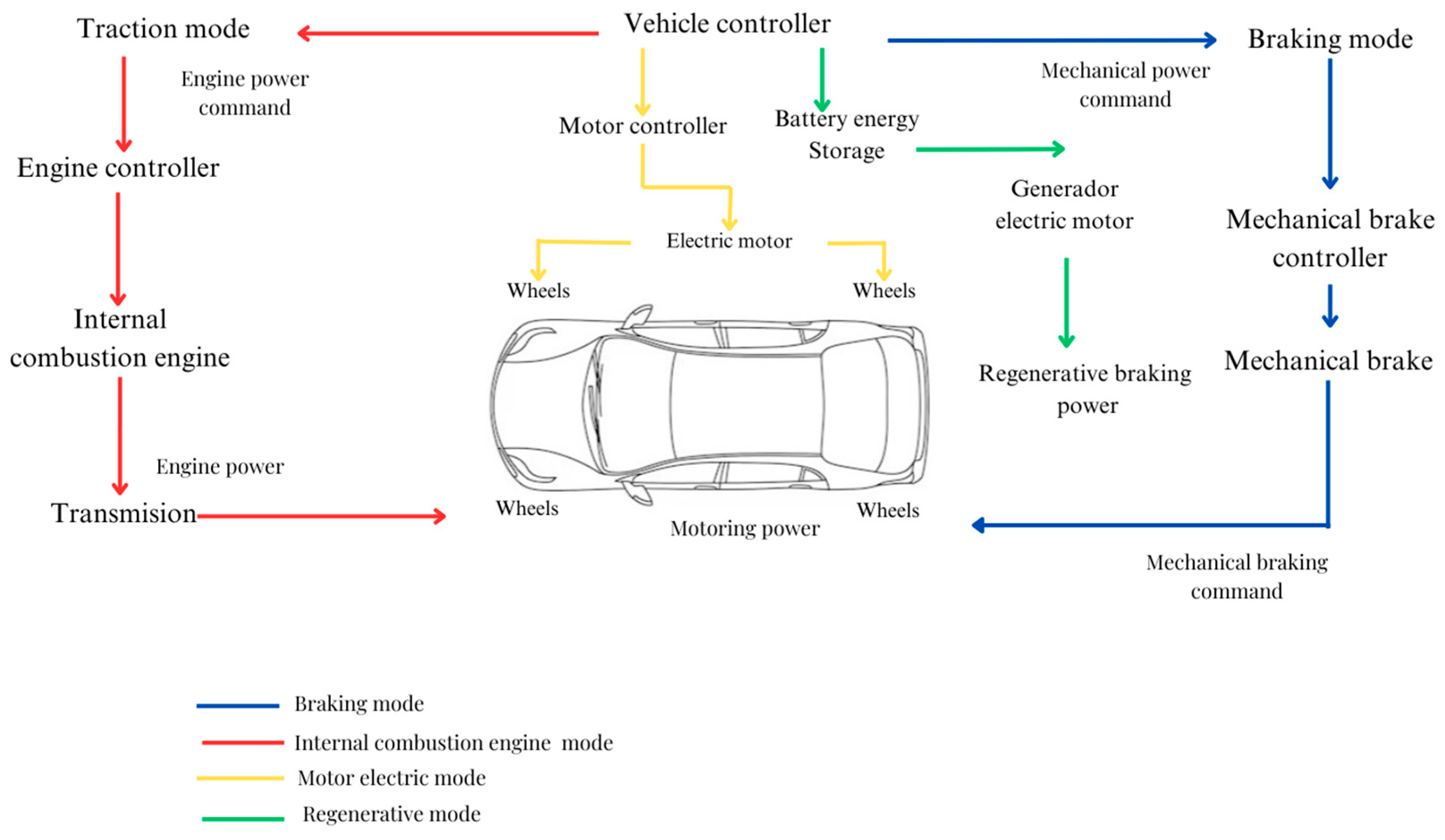
- Parallel Hybrid Vehicles (PHVs)—In this configuration, unlike the series powertrain, the heat engine and electric motor can drive the vehicle as they are both connected to the transmission, allowing their mechanical power to be transmitted individually or together. There are two types of mechanical coupling: torque and speed coupling. The advantages of the parallel configuration are as follows:
- No generator is needed.
- A smaller combustion engine is used.
- Since only a portion of the motor–engine power goes through multiple power conversions, it can be said that the efficiency of parallel hybrid powertrains is higher than that of series configurations.
- (C)
- Series-parallel hybrid cars (SPHVs)—This configuration complements the previous ones because the electric motor works alone at low speeds, while the thermal engine works together with the electric motor at high speeds. The only difference between this configuration and the previous ones is that it has another independent generator that produces electricity to power the electric motor.
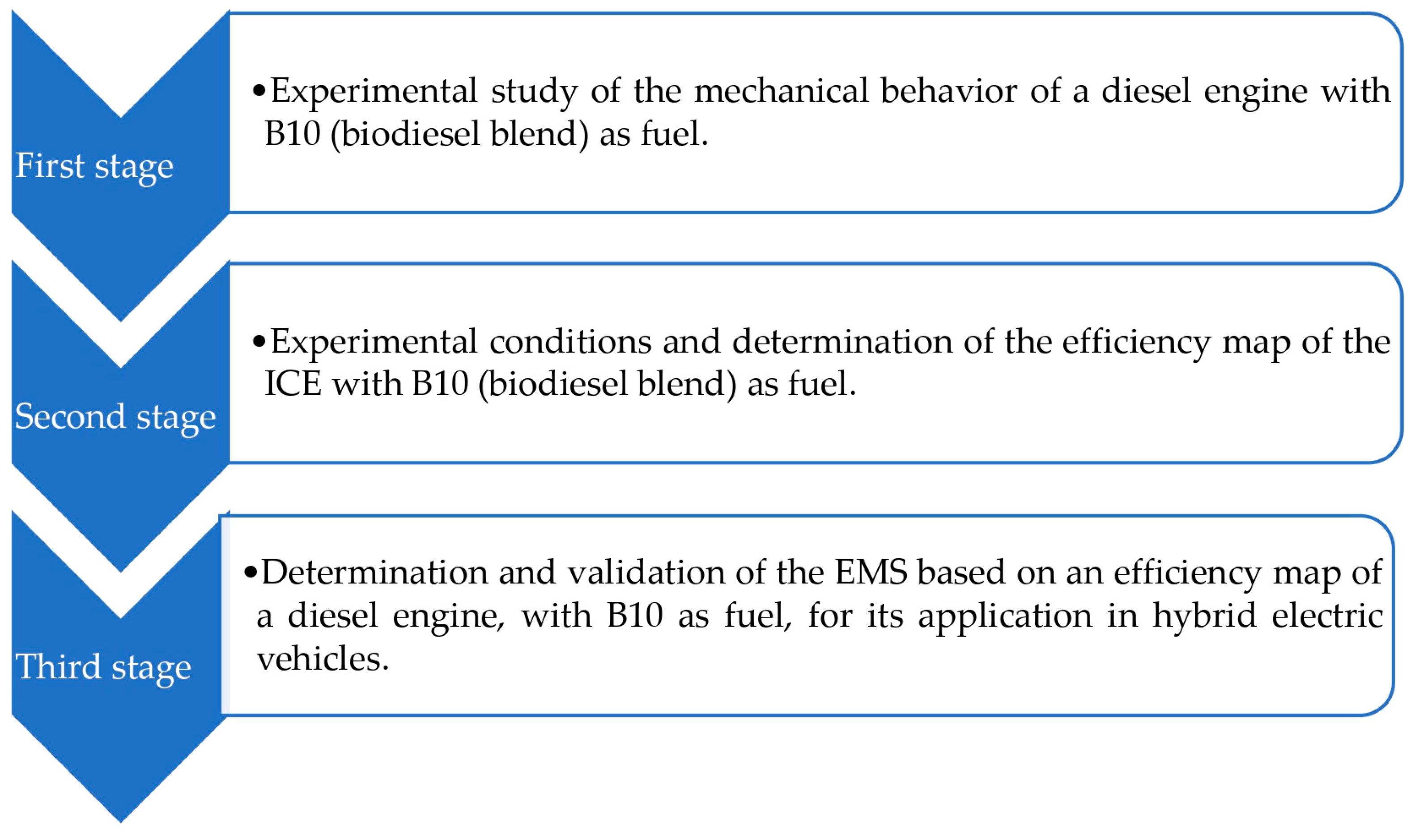
3. Methodology
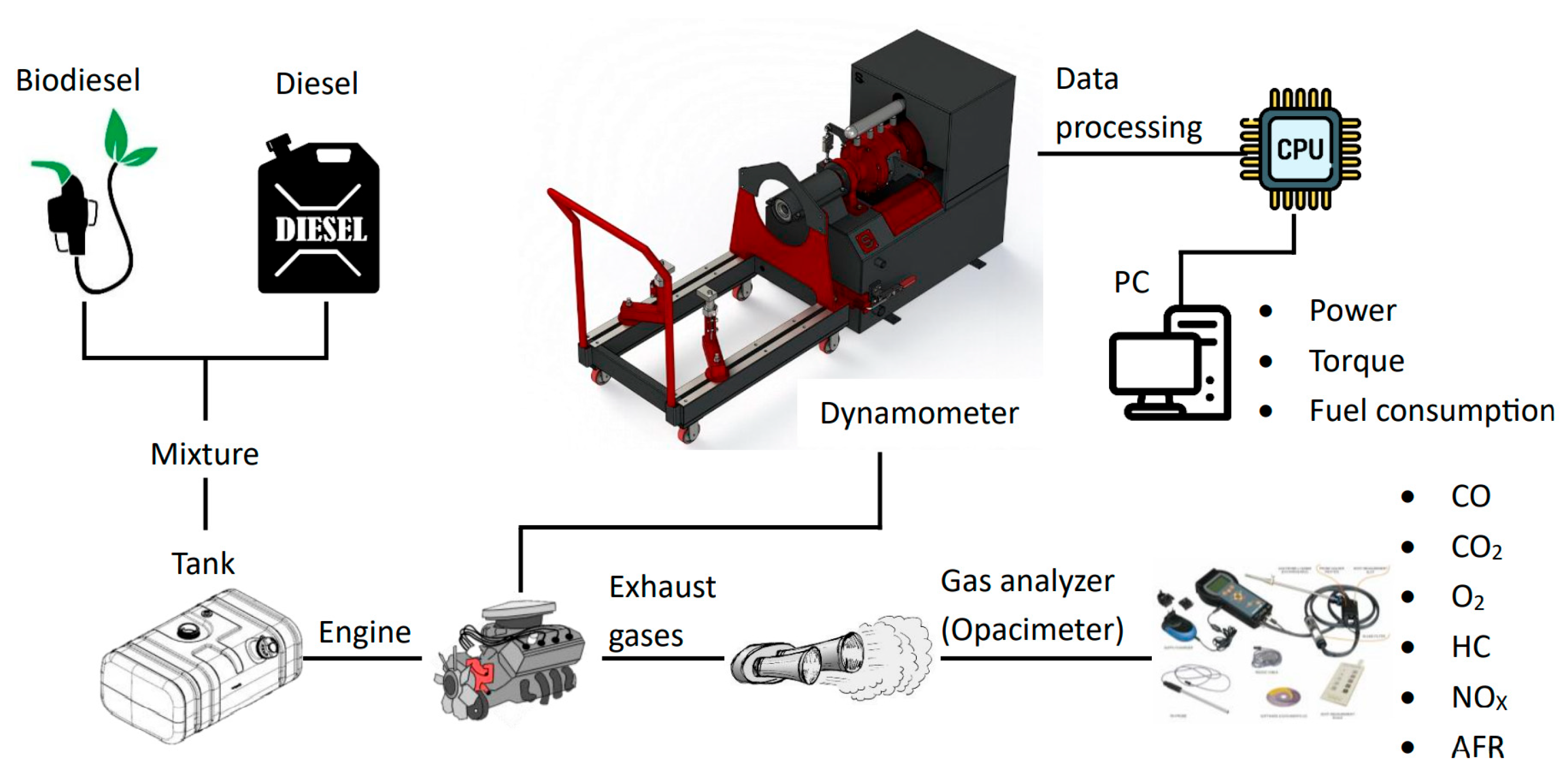
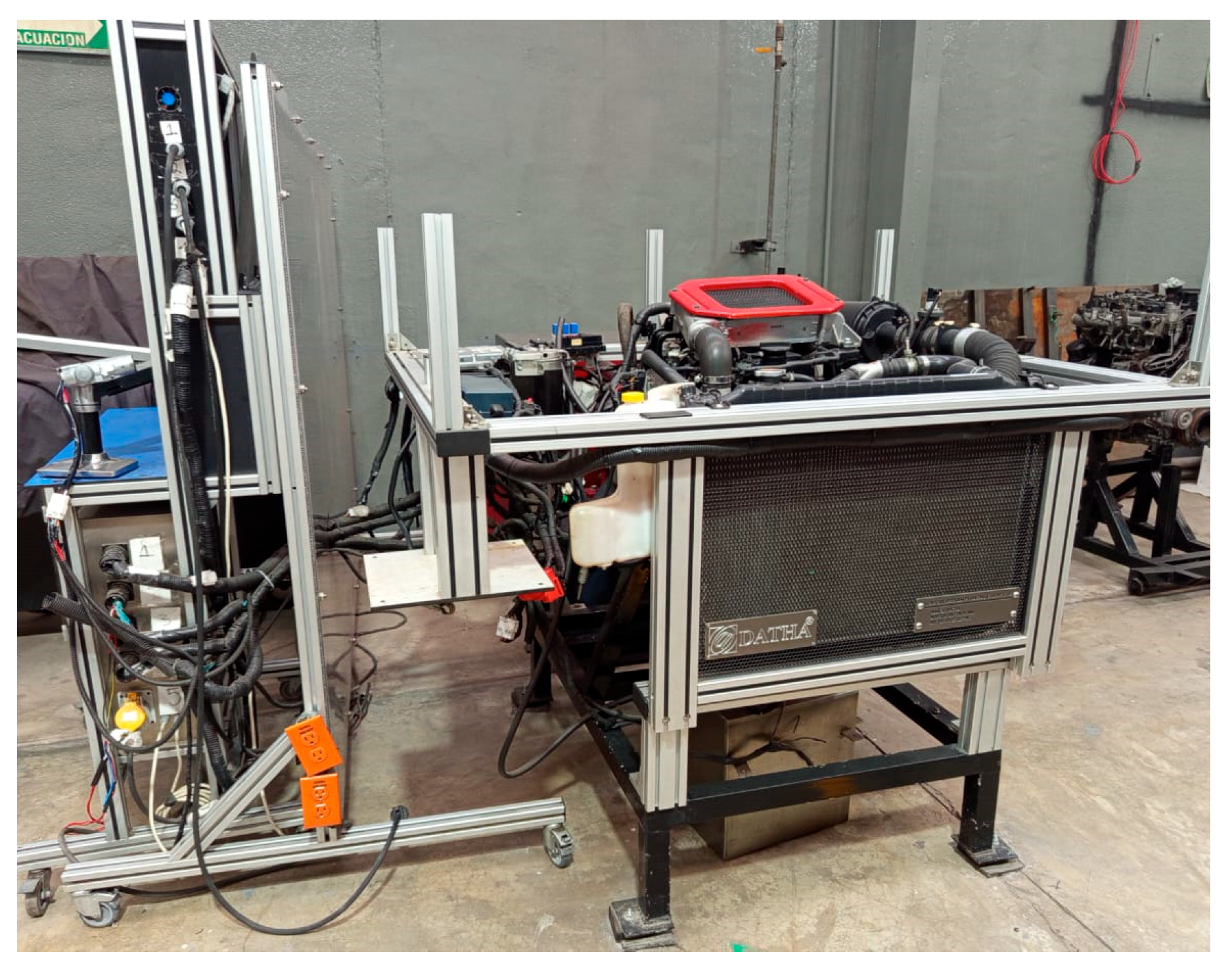
3.1. First Stage: Experimental Study of the Mechanical Behavior of a Diesel Engine with B10
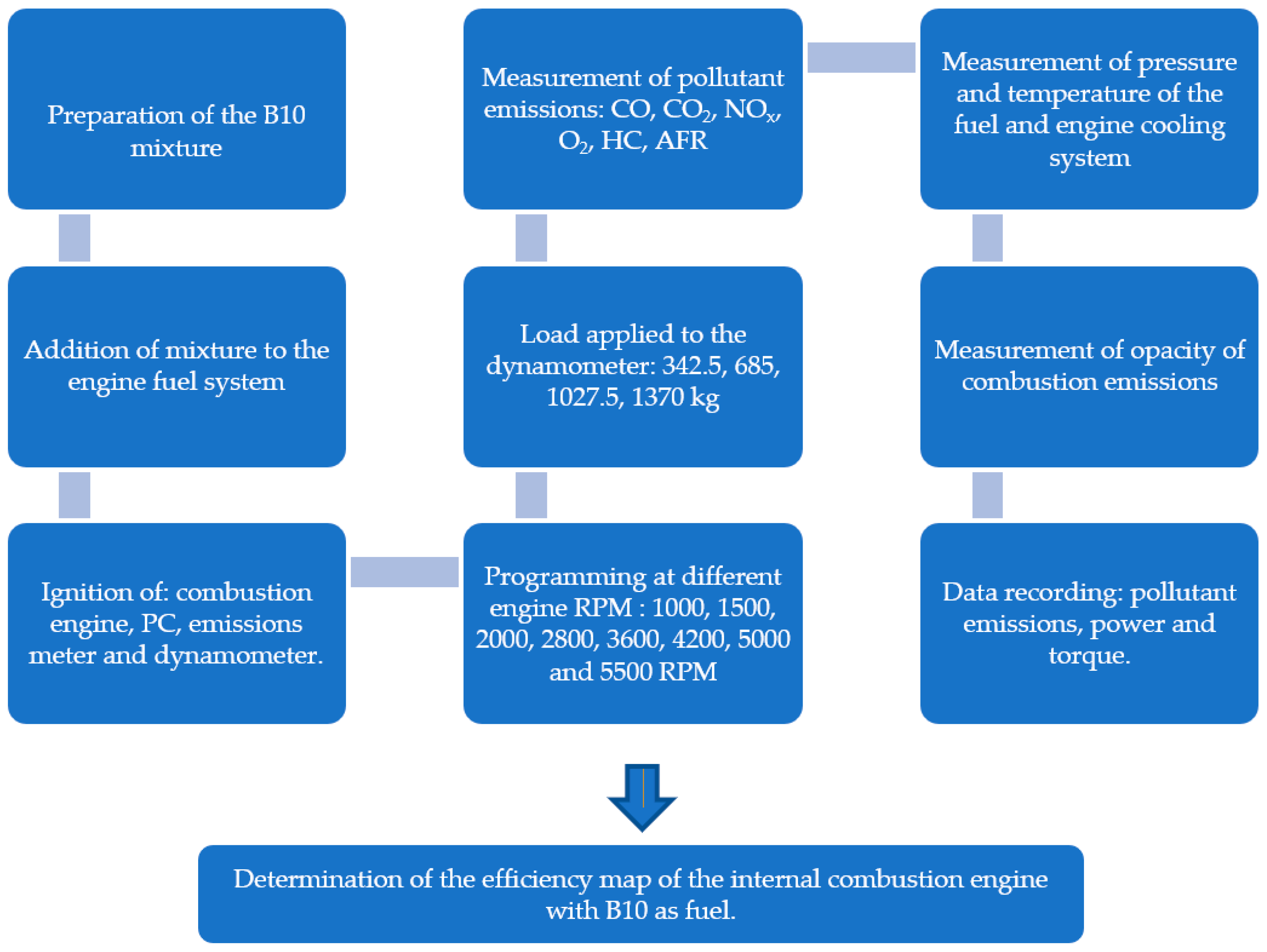
3.2. Second Stage: Experimental Conditions and Determination of the Efficiency Map of the ICE with B10
3.3. Third Stage: Determine and Validate the Energy Management Strategy Based on an Efficiency Map of a Diesel Engine with B10 as Fuel for Its Application in Hybrid Electric Vehicles
- (a)
- Efficiency map of the combustion engine with B10.
- (b)
- Determination of the maximum and minimum power and torque ranges.
- (c)
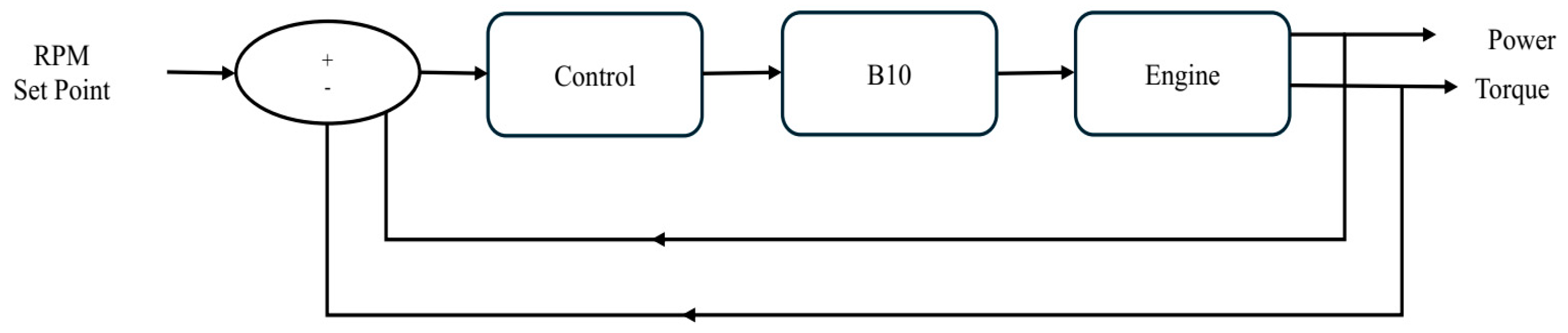
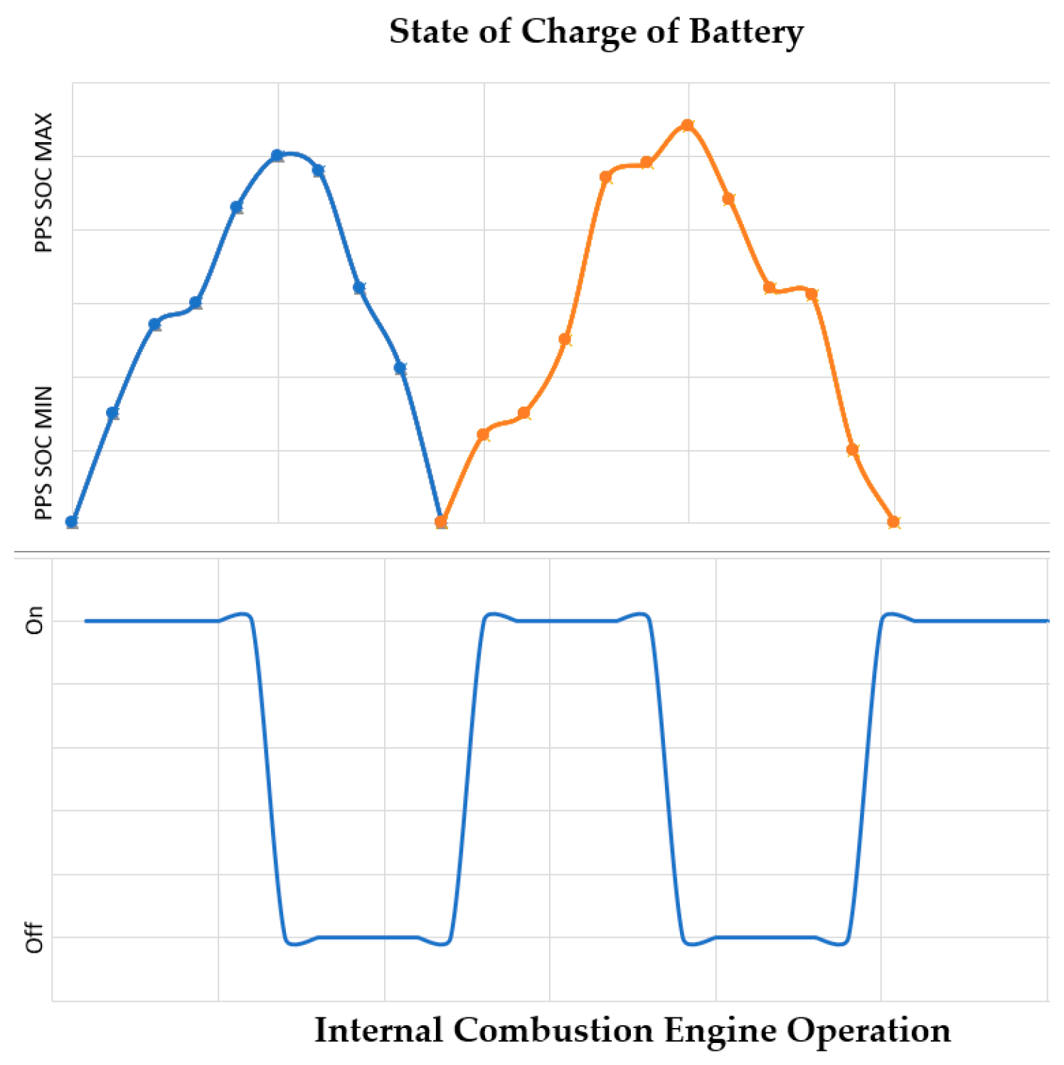
- Election of the engine on–off control strategy for the combustion engine.
- (d)
- Validation of the EMS with Advisor®.
4. Results and Discussion
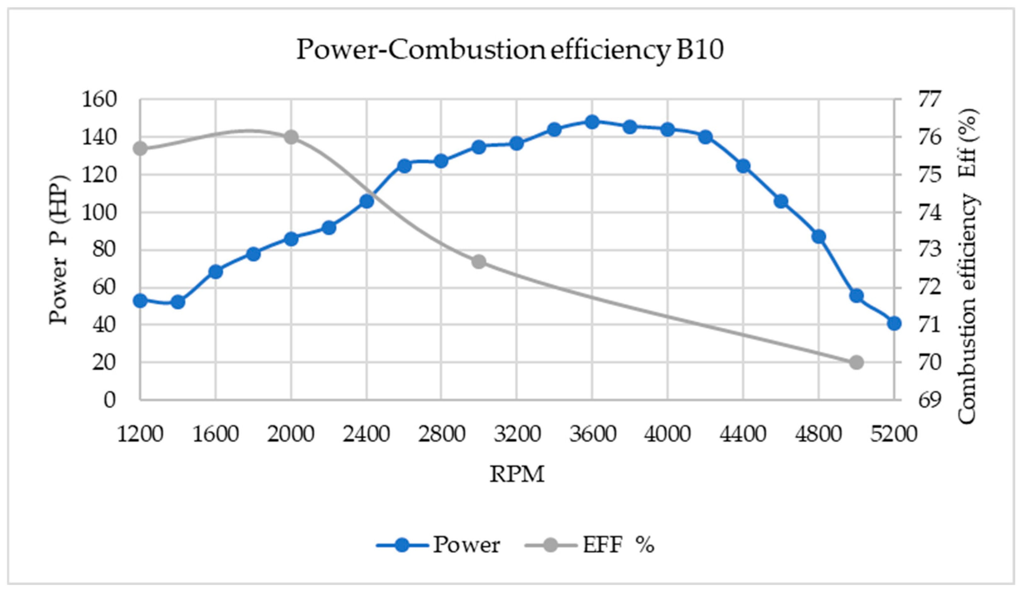
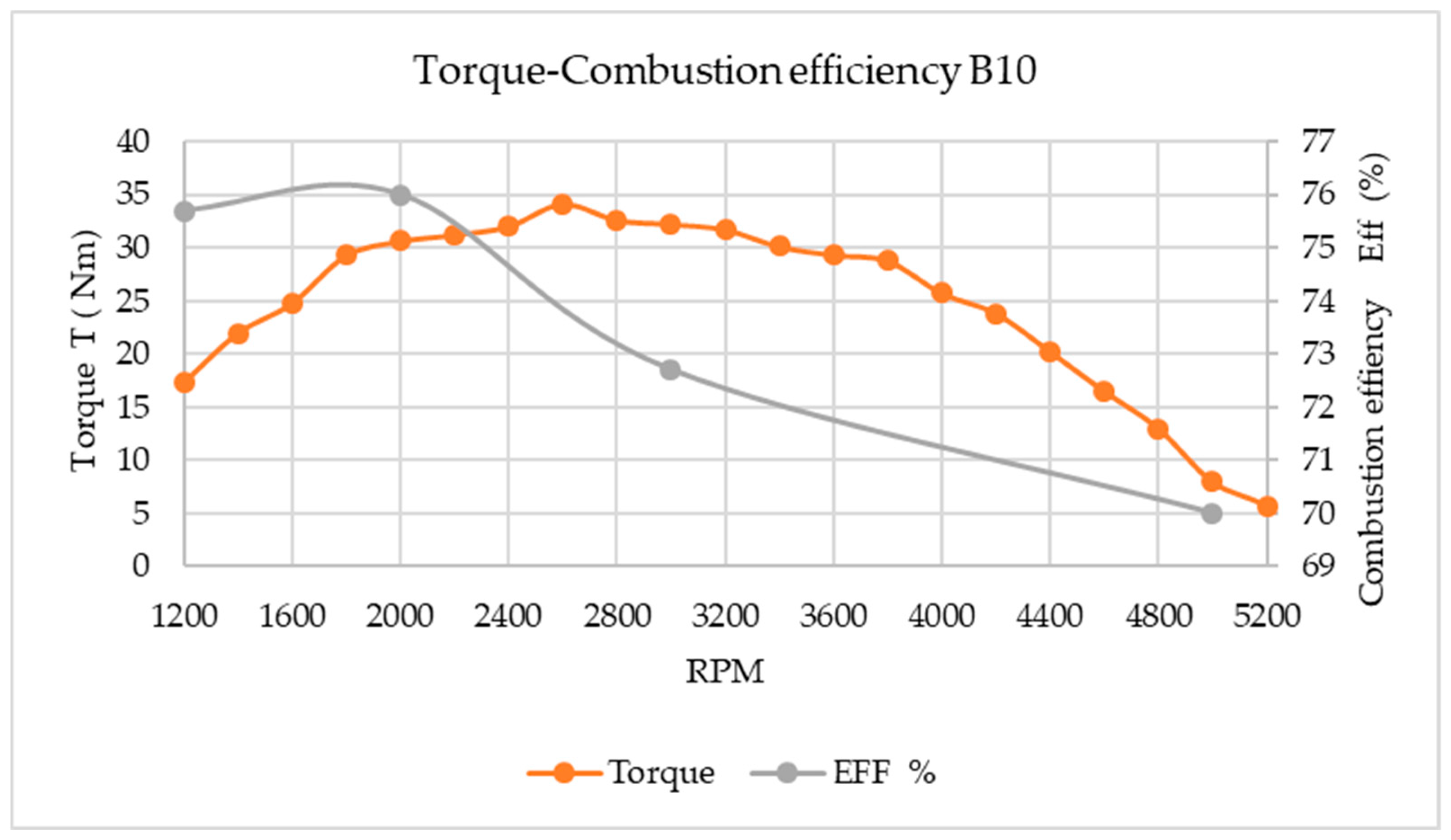
4.1. Stage 1 Results
4.2. Stage 2 Results: Analysis of Results and Determination of the Efficiency Map
4.3. Stage 3: Determination and Validation of the EMS Based on an Efficiency Map
4.3.1. Determination of the Energy Management Strategy Based on an Efficiency Map
4.3.2. Validation of the EMS Based on an Efficiency Map
Results in the UDDS
Results in the NEDC
5. Conclusions
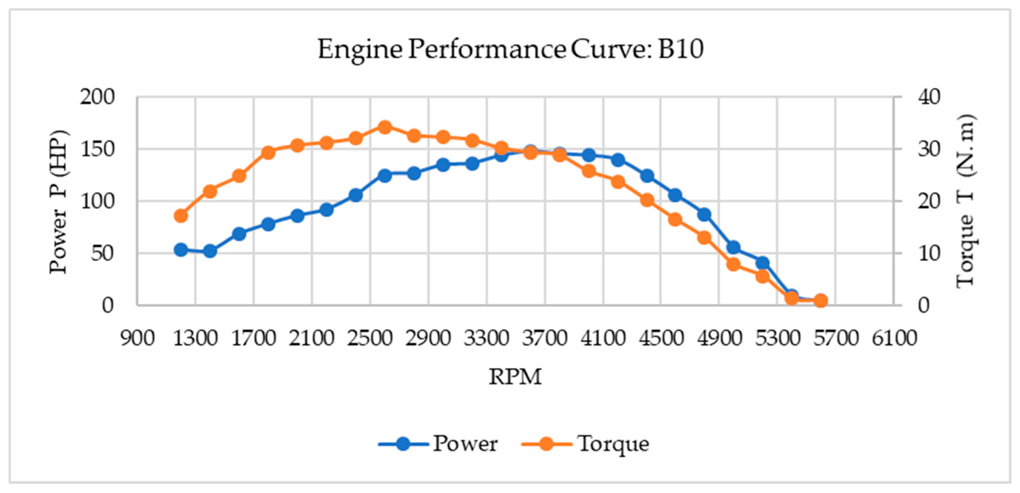
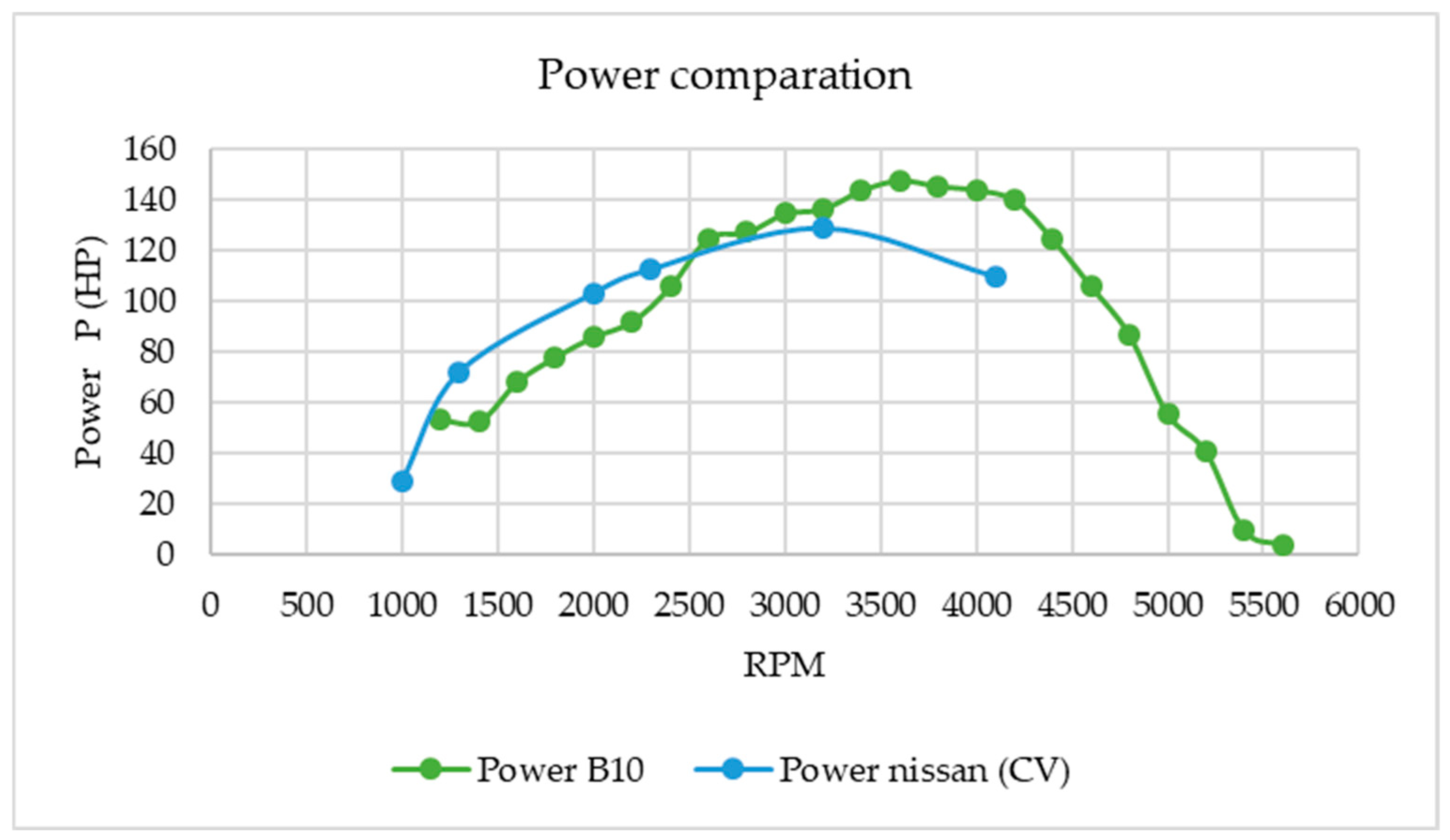
- The experimental power test with B10 presents a similarity with respect to the Nissan engine; there is very little variation.
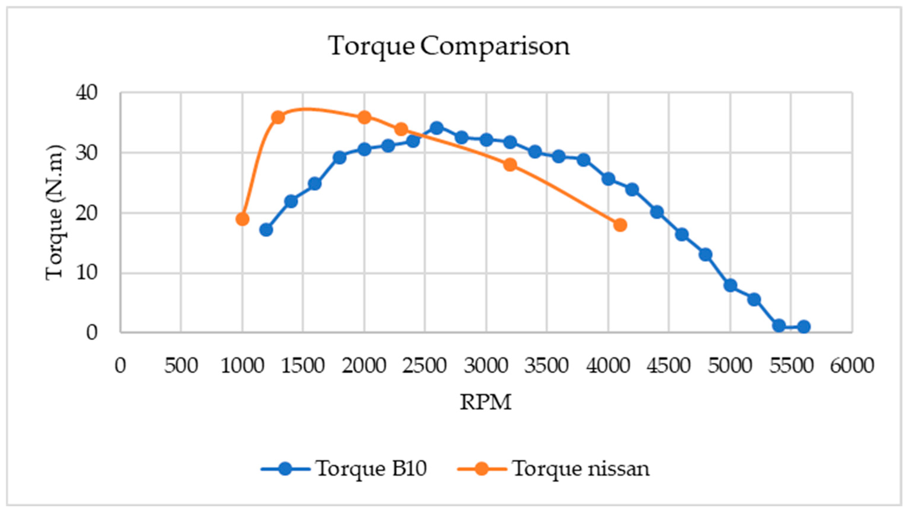
- The experimental torque test with B10 does present a decrease; this problem can be associated mainly with the physical and chemical characteristics of biodiesel.
- The polluting emissions are stable; however, it is important to mention that the engine in the experimental test has a turbocharger and EGR system, which can help improve combustion.
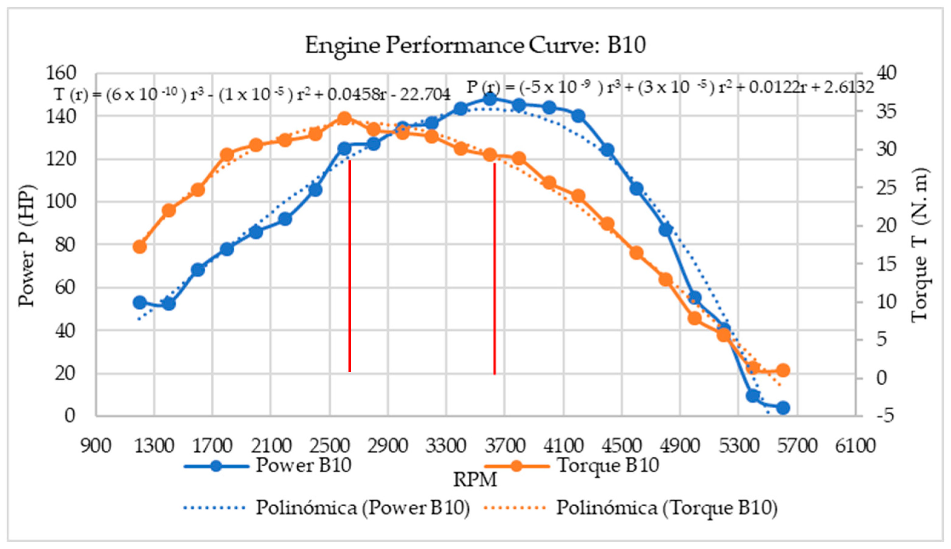
- An engine on–off control strategy with engine operating limits (2582 ≤ RPM ≤ 3680) was proposed, which was determined experimentally.
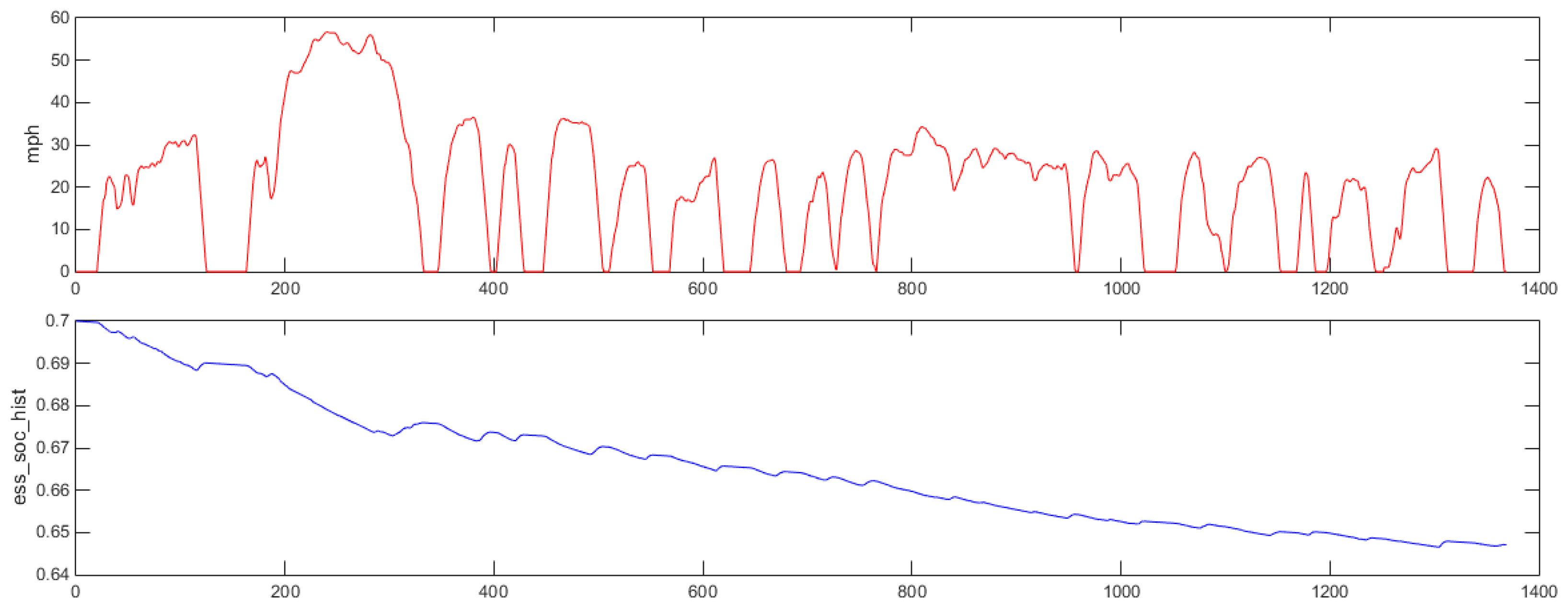
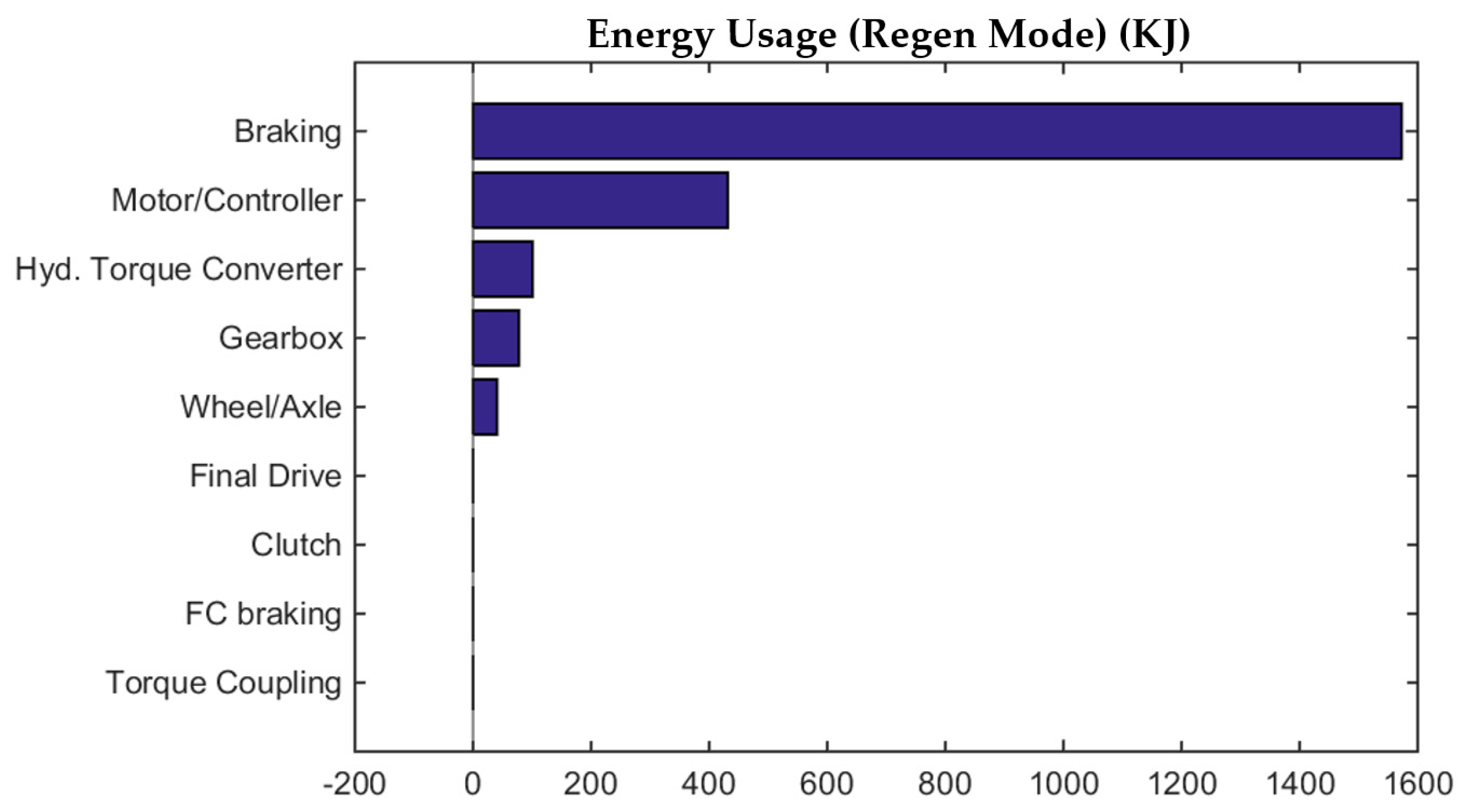
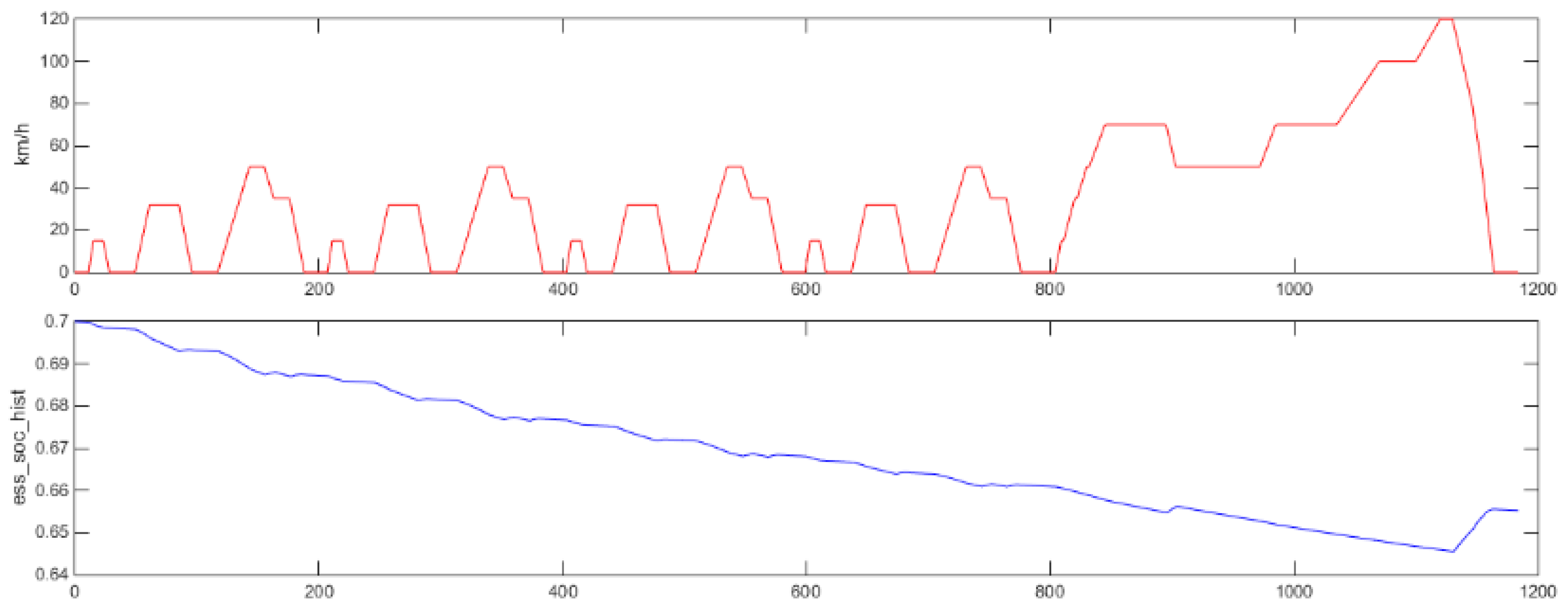
- The UDDS cycle describes an urban route where acceleration and braking are evident; it can be concluded that the HEV design meets the requirements of this cycle.
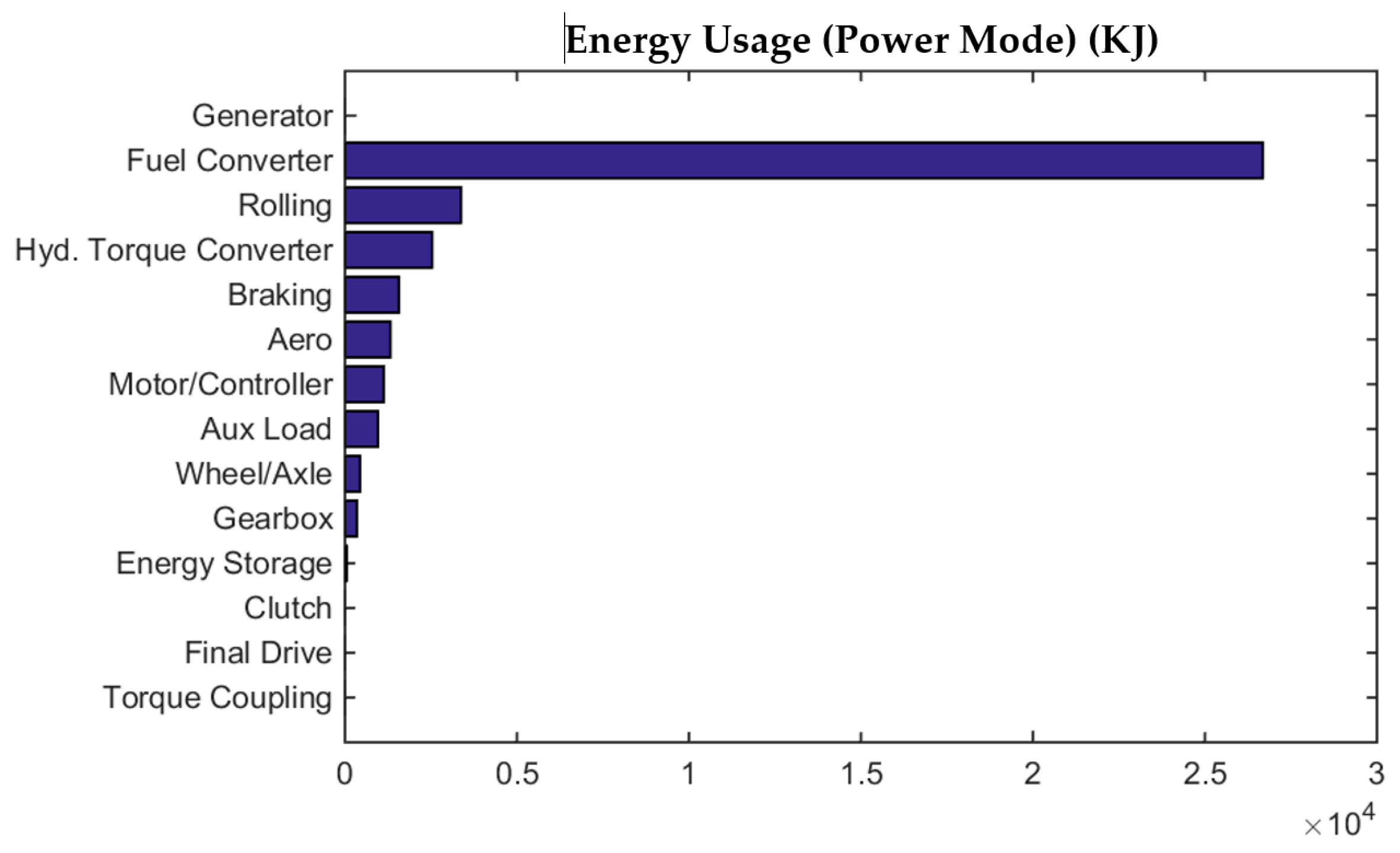
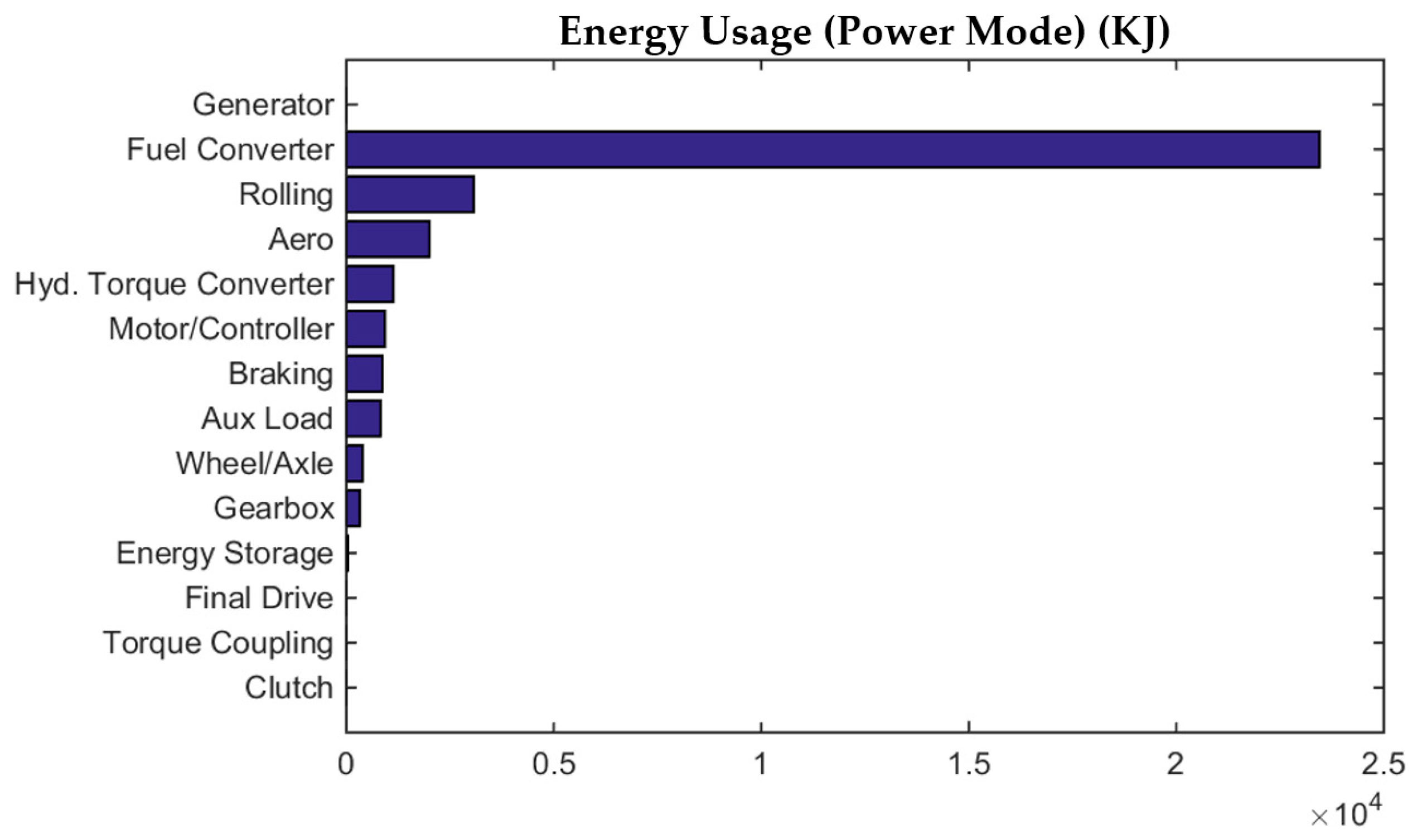
- In the UDDS cycle, rolling resistance and mechanical torque coupling are two systems that stand out in terms of losing a large amount of energy.
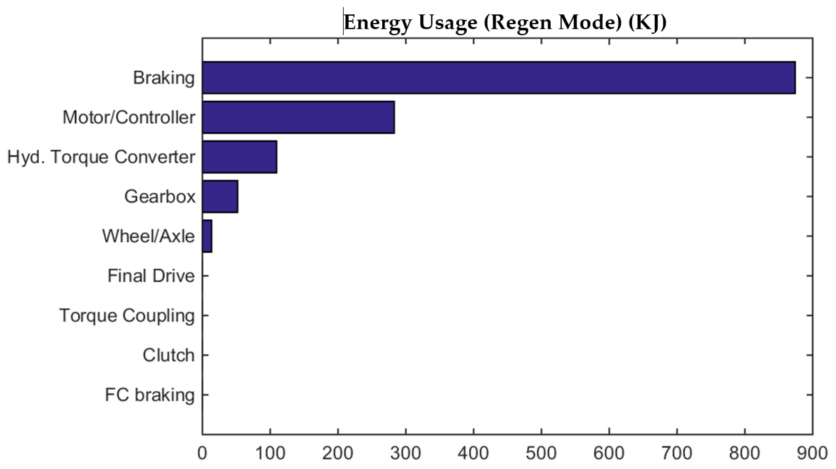
- In the UDDS cycle, the amount of available energy that can be used also stands out, mainly in the brake system and the electric motor.
- The performance of the HEV in the NEDC cycle meets the power and torque requirements. In the case of the SOC, it is more stable compared to the UDDS because it is an interurban cycle.
Supplementary Materials
Author Contributions
Funding
Data Availability Statement
Acknowledgments
Conflicts of Interest
Abbreviations
| HEVs | Hybrid Electric Vehicles |
| ICE | Internal Combustion Engine |
| EMS | Energy Management Strategy |
| EM | Energy Management |
| ECU | Engine Control Unit |
| ADP | Adaptive Dynamic Programming |
| HDP | Heuristic Dynamic Programming |
| ADP | Adaptive Dynamic Programming |
| AECMS | Adaptive Equivalent Consumption Minimization Strategy |
| DRL | Deep Reinforcement Learning |
| DL | Deep Learning |
| MARL | Multi-Agent Reinforcement Learning |
| ACC | Adaptive Cruise Control |
| PEMS | Proposed Energy Management Strategy |
| SHC | Series Hybrid Car |
| PHC | Parallel Hybrid Car |
| PHV | Parallel Hybrid Vehicle |
| DP | Dynamic Programming |
| SAC | Soft Actor–Critic |
| SAC-PL | Soft Actor–Criticism–Power Limit Constraint |
| DAML | Domain Adaptive Meta-Learning |
| MARL | Multi-Agent Reinforcement Learning |
| HOSS | Hierarchical Operation Switch Schedule |
| HBEV | Hybrid Biofuel Electric Vehicle |
| UDDS | Urban Dynamometer Driving Schedule |
| NEDC | New European Driving Cycle |
| ANN | Artificial Neural Network |
| MPC | Model Predictive Control |
| FDC | Forward Driving Cycle |
| PPS | Peak Power Source |
| PC | Predictive Control |
References
- Ramuhaheli, S.; Veeredhi, V.; Enweremadu, C. The Performance and Emission Characteristics Assessment of Hybrid Biodiesel/Ethanol Blends in a Diesel Engine. Rigas Teh. Univ. Zinat. Raksti 2022, 26, 670–683. [Google Scholar]
- Rimkus, A.; Mejeras, G.; Dittrich, A.; Pukalskas, S.; Barta, D. Effect of the Concentration of Bioethanol Mixed with Gasoline on the Energy and Environmental Performance of a Hybrid Vehicle in the Worldwide Harmonized Light Vehicles Test Cycle (WLTC). Appl. Sci. 2024, 14, 10858. [Google Scholar] [CrossRef]
- Özgur, T. A Study on the Performance and Emission Characteristics of a Diesel Engine Operated with Ternary Higher Alcohol Biofuel Blends. Ing. E Investig. 2023, 43, 1. [Google Scholar] [CrossRef]
- Sandaka, B.P.; Kumar, J. Alternative vehicular fuels for environmental decarbonization: A critical review of challenges in using electricity, hydrogen, and biofuels as a sustainable vehicular fuel. Chem. Eng. J. Adv. 2023, 14, 100442. [Google Scholar] [CrossRef]
- Wang, Z.; He, H.; Peng, J.; Chen, W.; Wu, C.; Fan, Y.; Zhou, J. A comparative study of deep reinforcement learning based energy management strategy for hybrid electric vehicle. Energy Convers. Manag. 2023, 293, 117442. [Google Scholar] [CrossRef]
- Tang, W.; Wang, Y.; Jiao, X.; Ren, L. Hierarchical energy management strategy based on adaptive dynamic programming for hybrid electric vehicles in car-following scenarios. Energy 2023, 265, 126264. [Google Scholar] [CrossRef]
- Zhou, Y. A regression learner-based approach for battery cycling ageing prediction―advances in energy management strategy and techno-economic analysis. Energy 2022, 256, 124668. [Google Scholar] [CrossRef]
- Ye, Y.; Wang, H.; Xu, B.; Zhang, J. An imitation learning-based energy management strategy for electric vehicles considering battery aging. Energy 2023, 283, 128537. [Google Scholar] [CrossRef]
- Oubelaid, A.; Khosravi, N.; Belkhier, Y.; Taib, N.; Rekioua, T. Health-conscious energy management strategy for battery/fuel cell electric vehicles considering power sources dynamics. J. Energy Storage 2023, 68, 107676. [Google Scholar] [CrossRef]
- Vignesh, R.; Ashok, B.; Kumar, M.S.; Szpica, D.; Harikrishnan, H.J. Adaptive neuro fuzzy inference system-based energy management controller for optimal battery charge sustaining in biofuel powered non-plugin hybrid electric vehicle. Sustain. Energy Technol. Assess. 2023, 59, 103379. [Google Scholar] [CrossRef]
- Qi, C.; Song, C.; Xiao, F.; Song, S. Generalization ability of hybrid electric vehicle energy management strategy based on reinforcement learning method. Energy 2022, 250, 123826. [Google Scholar] [CrossRef]
- Li, J.; Wu, X.; Hu, S.; Fan, J. A deep reinforcement learning based energy management strategy for hybrid electric vehicles in connected traffic environment. IFAC-Pap. 2021, 54, 150–156. [Google Scholar] [CrossRef]
- Hu, D.; Xie, H.; Song, K.; Zhang, Y.; Yan, L. An apprenticeship-reinforcement learning scheme based on expert demonstrations for energy management strategy of hybrid electric vehicles. Appl. Energy 2023, 342, 121227. [Google Scholar] [CrossRef]
- Sun, X.; Fu, J.; Yang, H.; Xie, M.; Liu, J. An energy management strategy for plug-in hybrid electric vehicles based on deep learning and improved model predictive control. Energy 2023, 269, 126772. [Google Scholar] [CrossRef]
- Wang, Y.; Wu, Y.; Tang, Y.; Li, Q.; He, H. Cooperative energy management and eco-driving of plug-in hybrid electric vehicle via multi-agent reinforcement learning. Appl. Energy 2023, 332, 120563. [Google Scholar] [CrossRef]
- Li, L.; Zhang, T.; Hong, J.; Zhang, H.; Yang, J.; Zhang, Z.; Wu, K. Energy management strategy of a novel mechanical–electro–hydraulic power coupling electric vehicle under smooth switching conditions. Energy Rep. 2022, 8, 8002–8016. [Google Scholar] [CrossRef]
- Mittal, V.; Shah, R. Energy Management Strategies for Hybrid Electric Vehicles: A Technology Roadmap. World Electr. Veh. J. 2024, 15, 424. [Google Scholar] [CrossRef]
- Jeyaseelan, T.; El Samad, T.; Rajkumar, S.; Chatterjee, A.; Al-Zaili, J. A techno-economic assessment of waste oil biodiesel blends for automotive applications in urban areas: Case of India. Energy 2023, 271, 127021. [Google Scholar] [CrossRef]
- Li, F.; Gao, L.; Zhang, Y.; Liu, Y. Hierarchical operation switch schedule algorithm for energy management strategy of hybrid electric vehicle using adaptive dynamic programming. Sustain. Energy Grids Netw. 2023, 35, 101107. [Google Scholar] [CrossRef]
- Zhang, H.; Peng, J.; Dong, H.; Tan, H.; Ding, F. Hierarchical reinforcement learning based energy management strategy of plug-in hybrid electric vehicle for ecological car-following process. Appl. Energy 2023, 333, 120599. [Google Scholar] [CrossRef]
- Lü, X.; Li, S.; He, X.; Xie, C.; He, S.; Xu, Y.; Fang, J.; Zhang, M.; Yang, X. Hybrid electric vehicles: A review of energy management strategies based on model predictive control. J. Energy Storage 2022, 56, 106112. [Google Scholar] [CrossRef]
- Siddhartha, P.; Sujeeth, T.; Shiva, B.; Ramprabhakard, J. Integration of renewable energy sources with power management strategy for effective bidirectional vehicle to grid power transfer. Procedia Comput. Sci. 2023, 218, 9–23. [Google Scholar] [CrossRef]
- Ehsani, M.; Gao, Y.; Longo, S.E. Modern Electric, Hybrid Electric, and Fuel Cell Vehicles, 2nd ed.; Fundametals, Theory, and Design; CRC Press: Boca Ratón, FL, USA, 2018. [Google Scholar]
- Dong, P.; Zhao, J.; Liu, X.; Wu, J.; Xu, X.; Liu, Y.; Wang, S.; Guo, W. Practical application of energy management strategy for hybrid electric vehicles based on intelligent and connected technologies: Development stages, challenges, and future trends. Renew. Sustain. Energy Rev. 2022, 170, 112947. [Google Scholar] [CrossRef]
- ASTM PS121-99; Provisional Specification for Biodiesel Fuel (B100) Blend Stock for Distillate Fuels. ASTM International: West Conshohocken, PA, USA, 2017.
- ASTM D975-20; Standard Specification for Diesel Fuel. ASTM International: West Conshohocken, PA, USA, 2020.
- ASTM D6751-18; Standard Specification for Biodiésel Fuel Blend Stock (B100) for Middle Distillate Fuels. ASTM International: West Conshohocken, PA, USA, 2018.
- Paredes Rojas, J.C.; Torres San Miguel, C.R.; Vázquez Medina, R.; Leal Naranjo, J.A.; Ortiz Hernández, F.E.; Costa Castelló, R. Pollutant emissions and combustion efficiency assessment of engines using biodiesel. Appl. Sci. 2020, 10, 8646. [Google Scholar] [CrossRef]
- Naik, N.S.; Balakrishna, B. A comparative study of B10 biodiesel blends and its performance and combustion characteristics. Int. J. Ambient. Energy 2017, 39, 257–263. [Google Scholar] [CrossRef]
- Wäring, J.; Svanberg, K. Characterization of Chemical Decomposition of Biodiesel, with a Focus on B10, B30 and B100 Blends. Master’s Thesis, Division of Applied Surface Chemistry, Chalmers University Of Technology, Gothenburg, Sweden, 2012. [Google Scholar]
- Mu, Z.; Fu, J.; Zhou, F.; Yuan, K.; Yu, J.; Huang, D.; Cui, Z.; Duan, X.; Liu, J. A Comparatively Experimental Study on the Performance and Emission Characteristics of a Diesel Engine Fueled with Tung Oil-Based Biodiesel Blends (B10, B20, B50). Energies 2023, 16, 5577. [Google Scholar] [CrossRef]
- Nissan Yd25Ddti/L4 Dohc (Diesel) 2.5 L, Manual Repair and Service. 2012. Available online: https://www.nissan.co.th/content/dam/Nissan/th/owners/Navara_EN_Owner_Manual.pdf (accessed on 10 March 2025).
- Cengel, Y.A.; Boles, M.A. Termodinámica, 8th ed.; Mc Graw Hill: Ciudad de México, Mexico, 2015; pp. 60–783. [Google Scholar]
- Heywood, J.B.L. Internal Combustion Engine Fundamentals; McGraw-Hill: New York, NY, USA, 1988. [Google Scholar]
- Eckert, J.J.; Silva, F.L.; da Silva, S.F.; Bueno, A.V.; de Oliveira, M.L.; Silva, L.C. Optimal design and power management control of hybrid biofuel–electric powertrain. Appl. Energy 2022, 325, 119903. [Google Scholar] [CrossRef]
- Dziubak, T.; Karczewski, M. Experimental Studies of the Effect of Air Filter Pressure Drop on the Composition and Emission Changes of a Compression Ignition Internal Combustion Engine. Energies 2022, 15, 4815. [Google Scholar] [CrossRef]
- Saiteja, P.; Ashok, B. Critical review on structural architecture, energy control strategies and development process towards optimal energy management in hybrid vehicles. Renew. Sustain. Energy Rev. 2022, 157, 112038. [Google Scholar] [CrossRef]
- Zhao, J.; Chen, P.; Ibrahim, U.; Wang, J. Comparative Study and Accommodation of Biodiesel in Diesel-Electric Hybrid Vehicles Coupled with Aftertreatment Systems. Asian J. Control 2016, 18, 3–15. [Google Scholar] [CrossRef]
- Pakalapati, J.; Surakasi, R.; Kilari, A.; Nagamani, K.; Tamvada, K. Nano-dispersed Corn Oil Biodiesel: An Analysis of its Potential for usage in Hybrid Electric Vehicles. Int. J. Veh. Struct. Syst. 2024, 16, 83–88. Available online: https://www.researchgate.net/profile/Raviteja-Surakasi/publication/378804290_Nano-dispersed_Corn_Oil_Biodiesel_An_Analysis_of_its_Potential_for_usage_in_Hybrid_Electric_Vehicles/links/65eadaf3b1906066b274e7cb/Nano-dispersed-Corn-Oil-Biodiesel-An-Analysis-of-its-Potential-for-usage-in-Hybrid-Electric-Vehicles.pdf (accessed on 10 March 2025).
- Mourad, M.; Mohamed, F.; Mahmoud, K.; Nouh, A. Influence of Biodiesel Fuel on Performance Characteristics of Hybrid Electric Vehicle According to Urban Driving Cycle. In Proceedings of the Fifth International Renewable Energy Congress IREC, Hammamet, Tunisia, 25–27 March 2014. [Google Scholar]

| Parameter | Dynamometer | Nissan® YD25DDTi Engine |
|---|---|---|
| Brand | Saenz® | Nissan® |
| Model | DS3 | YD25DDTi |
| Software | Own, real-time analysis | - |
| Tests performed | Torque, power, and efficiency | - |
| Engine type | - | Diesel, common rail |
| Number of cylinders | - | 4 in-line |
| Displacement | - | 2.4 L |
| Maximum power | 900 HP at 4000 rpm | 131 HP at 3600 rpm |
| Maximum torque | - | 304 N·m at 2000 rpm |
| Compression ratio | - | 16.5:1 |
| Vehicles in which it is used | - | Nissan® NP300, Navara®, Frontier® |
| Properties | Diesel | Biodiesel |
|---|---|---|
| ASTM D975 | ASTM PS 121 ASTM D6751-18 | |
| Kinetic viscosity at 40 °C (mm2/s) | 1.3–4.1 | 1.9–6 |
| Specific gravity at 15 °C | 0.85 | 0.88 |
| Density (lb/gal) | 7.079 | 7.328 |
| Carbon (%) | 87 | 77 |
| Hydrogen (%) | 13 | 12 |
| Oxygen (%) | 0 | 11 |
| Sulfur (%) | 0.05 | 0.0024 |
| Flashpoint (°C) | 60–80 | 100–70 |
| Cetane number | −35–15 | −15–10 |
| Stoichiometric radio (air/fuel: parts air to 1 part fuel) (stratified) | 40–55 | 48–65 |
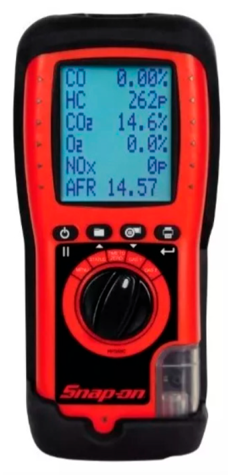
| Pollutant Gas | Range | Precision |
|---|---|---|
| CO | 0–5% | ÷10% |
| CO2 | ± | |
| O2 | 0–21% | ≤5% |
| HC | 0–2000 PPM | ÷10% |
| NOx | 0–1500 PPM | ±10% |
| System | Technical Characteristics |
|---|---|
| Combustion Engine | 2.5 L (88 kW) turbo diesel engine |
| Exhaust Aftertreatment | Close-coupled catalyst for CI engine |
| Energy Storage System | Internal resistance battery model; 28 Ah NiMH HEV battery (nickel metal hydride) |
| Powertrain Control | Parallel, multi-spd parallel electric-assist hybrid w/ electric launch |
| Motor Electric | 75 kW (continuous) AC induction motor/inverter |
| Transmission | 4-spd automatic transmission |
| Torque Coupling | Lossless belt drive |
| Wheel/Axle | Constant coefficient of rolling resistance model/axle assembly for SUV |
| Accessory | 700 W constant |
| Powertrain Control | Efficiency mode operation |
| Traction | Rear wheel drive |
| System | Max Power (kW) | Peak Eff | Mass (kg) |
|---|---|---|---|
| Vehicle | 1408 | ||
| Combustion engine | 90 | 0.42 | 380 |
| Exhaust after treatment | 27 | ||
| Motor electric | 75 | 0.92 | 91 |
| Transmission | 1 | 114 | |
| Torque coupling | 1 | ||
| Cargo mass | 136 | ||
| # of modes | V nom | ||
| Energy storage system | 65 | 436 | 234 |
| Calculated mass | 2390 |
Disclaimer/Publisher’s Note: The statements, opinions and data contained in all publications are solely those of the individual author(s) and contributor(s) and not of MDPI and/or the editor(s). MDPI and/or the editor(s) disclaim responsibility for any injury to people or property resulting from any ideas, methods, instructions or products referred to in the content. |
© 2025 by the authors. Licensee MDPI, Basel, Switzerland. This article is an open access article distributed under the terms and conditions of the Creative Commons Attribution (CC BY) license (https://creativecommons.org/licenses/by/4.0/).
Share and Cite
Paredes-Rojas, J.C.; Costa-Castelló, R.; Vázquez-Medina, R.; Flores-Campos, J.A.; Torres-San Miguel, C.R. Experimental Study on Using Biodiesel in Hybrid Electric Vehicles. Energies 2025, 18, 1621. https://doi.org/10.3390/en18071621
Paredes-Rojas JC, Costa-Castelló R, Vázquez-Medina R, Flores-Campos JA, Torres-San Miguel CR. Experimental Study on Using Biodiesel in Hybrid Electric Vehicles. Energies. 2025; 18(7):1621. https://doi.org/10.3390/en18071621
Chicago/Turabian StyleParedes-Rojas, Juan Carlos, Ramón Costa-Castelló, Rubén Vázquez-Medina, Juan Alejandro Flores-Campos, and Christopher Rene Torres-San Miguel. 2025. "Experimental Study on Using Biodiesel in Hybrid Electric Vehicles" Energies 18, no. 7: 1621. https://doi.org/10.3390/en18071621
APA StyleParedes-Rojas, J. C., Costa-Castelló, R., Vázquez-Medina, R., Flores-Campos, J. A., & Torres-San Miguel, C. R. (2025). Experimental Study on Using Biodiesel in Hybrid Electric Vehicles. Energies, 18(7), 1621. https://doi.org/10.3390/en18071621