Three-Level All-SiC High-Frequency High-Voltage Plasma Power Supply System
Abstract
1. Introduction
2. The Design of High-Frequency High-Voltage Plasma Power Supply
2.1. Overall Structure of High-Frequency High-Voltage Plasma Power Supply Hardware System
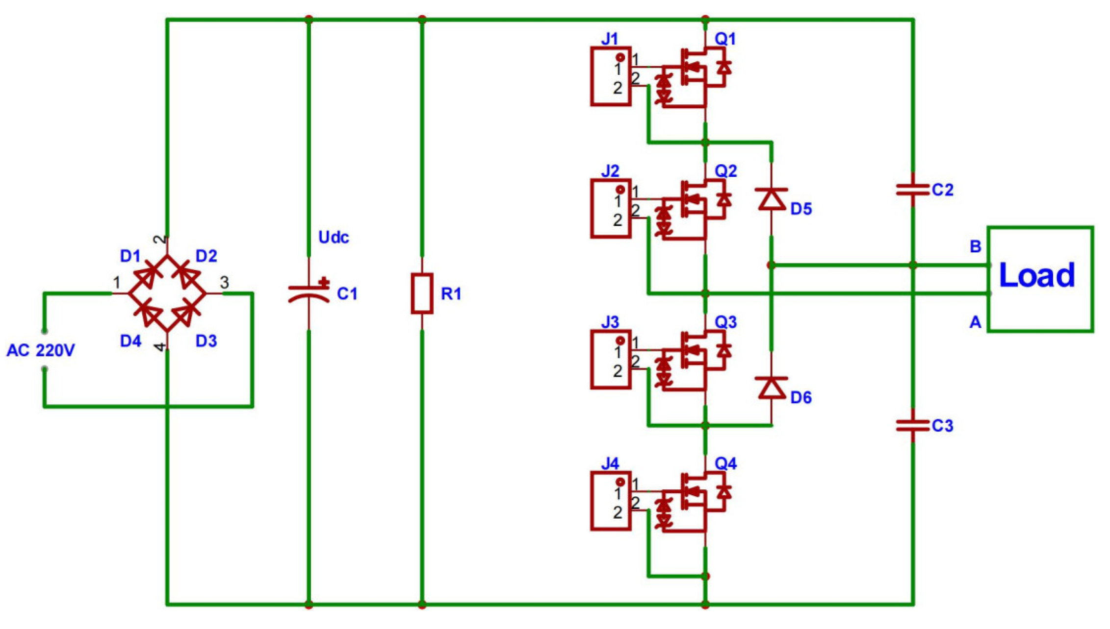
- Inverter main circuit: the system uses an NPC diode-clamped three-level inverter as the main circuit of the system to convert DC power to AC power;
- MCU control system: this generates a PWM drive signal to drive the switching tube on and off so that the inverter main circuit outputs AC power to realize the inverter function. This design adopts the MCU control system based on an ARM 32-bit Cortex-M4F microcontroller AT32F403ARCT7 developed by Chongqing, China as the core [22];
- Isolation circuit: the MCU control system and the drive circuit are electrically isolated to ensure that the control signals generated by the MCU control system are not interfered with by the strong external electric parts [23], which stabilizes and guarantees the safe operation of the MCU control system [24];
- Drive circuit: the PWM signal generated by the MCU control system is amplified to drive the switching tube of the inverter main circuit and it is used to turn MOSFETs on and off.
2.2. Design of the Three-Level High-Frequency Inverter Main Circuit
- Reduction in the number of components and cost reduction:
- 2.
- Overall loss reduction:
- Better output waveform:
- 2.
- Improvement in electromagnetic interference (EMI) problems:
- 3.
- Lower loss, higher efficiency, and higher switching frequency:
2.2.1. Selection of Power MOSFETs
2.2.2. Selection of Voltage Divider Capacitors
- C is the value of the voltage dividing capacitance (in Farad, F);
- Iav is the effective value of the busbar current (in Amperes, A);
- f is the switching frequency (in Hertz, Hz);
- Δv is the permissible midpoint voltage ripple (in Volts, V), typically 1% to 2% of the bus voltage.
2.2.3. Selection of Clamp Diodes
2.3. Design of the Three-Level High-Frequency Control Main Circuit
2.3.1. Drive Circuit Design
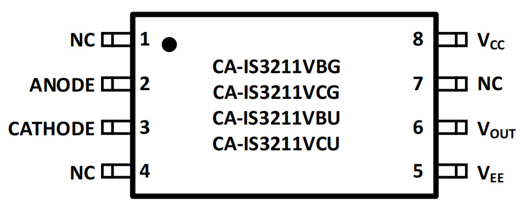
- Low common-mode transient immunity (CMTI): a low CMTI can lead to false triggering or output switching errors due to transient noise at high switching frequencies;
- High transmission delay: especially in high-speed switching applications, high transmission delay affects the response speed of the PWM signal;
- High pulse width distortion: this increases the deviation between the PWM signal pulse width and the ideal value, reducing system performance and reliability.
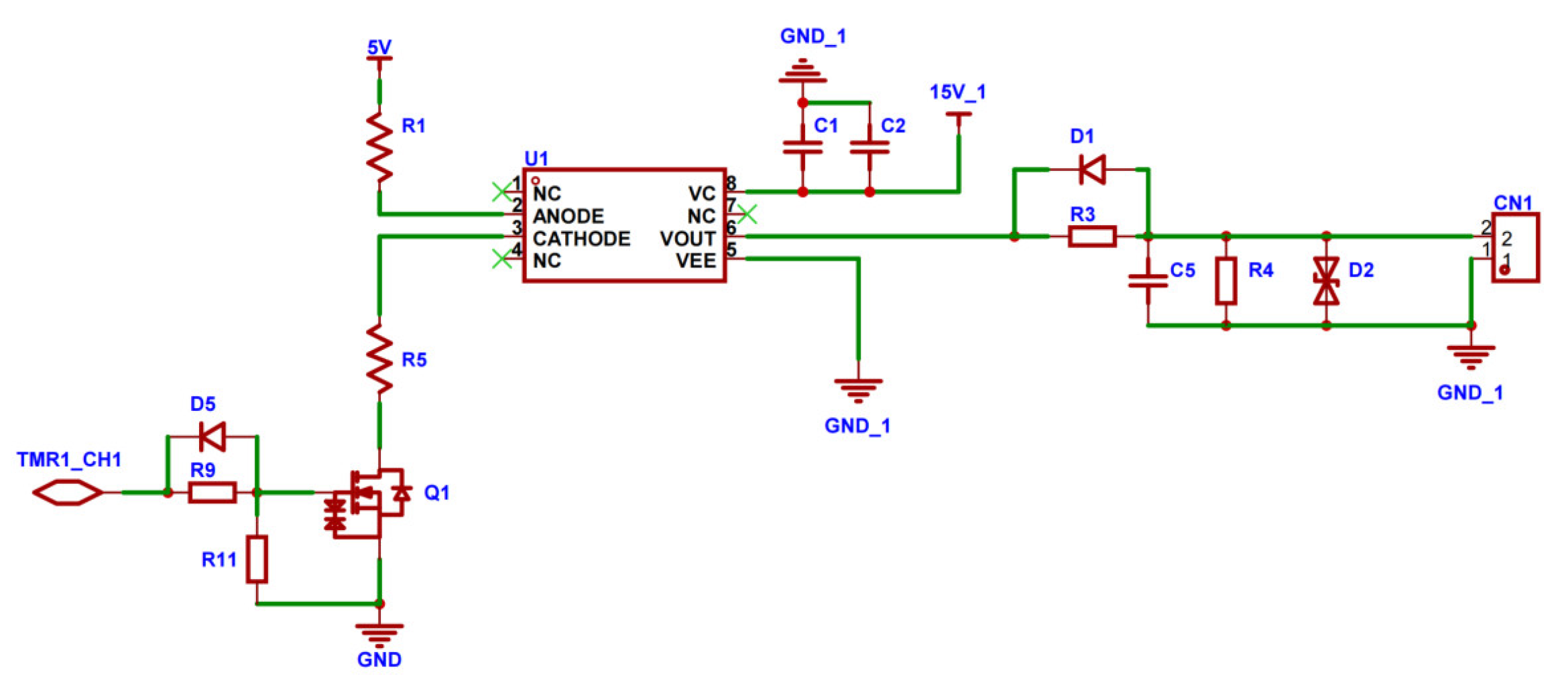
- R11: gate resistor to control gate charging and discharging speed;
- C2: 15 V power supply filtering capacitor;
- R3 and R9: current-limiting resistors;
- C5 and R4: filtering components;
- D2: TVS tube to protect against instantaneous surge pulse voltages;
- D1 and D5: continuity diodes to prevent reverse current damage.
2.3.2. Design of the Isolated Power Supply Circuit
- C13, C14, and C25: power filtering capacitors;
- C21: isolation capacitor to isolate the ground of input 24 V from the ground of output 15 V.
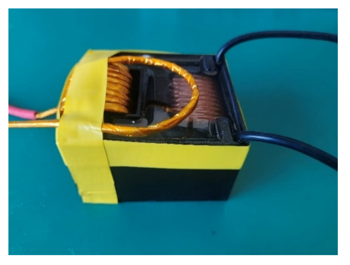
2.4. Design of the High-Frequency High-Voltage Transformer
2.4.1. Selection of Transformer Primary Wire
2.4.2. Selection of Transformer Materials
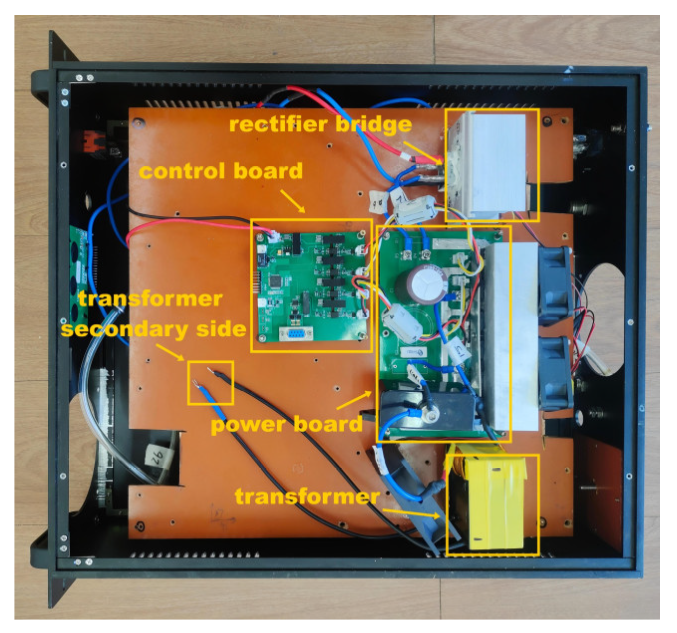
2.5. Device of the High-Frequency High-Voltage Plasma Power Supply System
2.6. Discussion of PWM Control Strategies
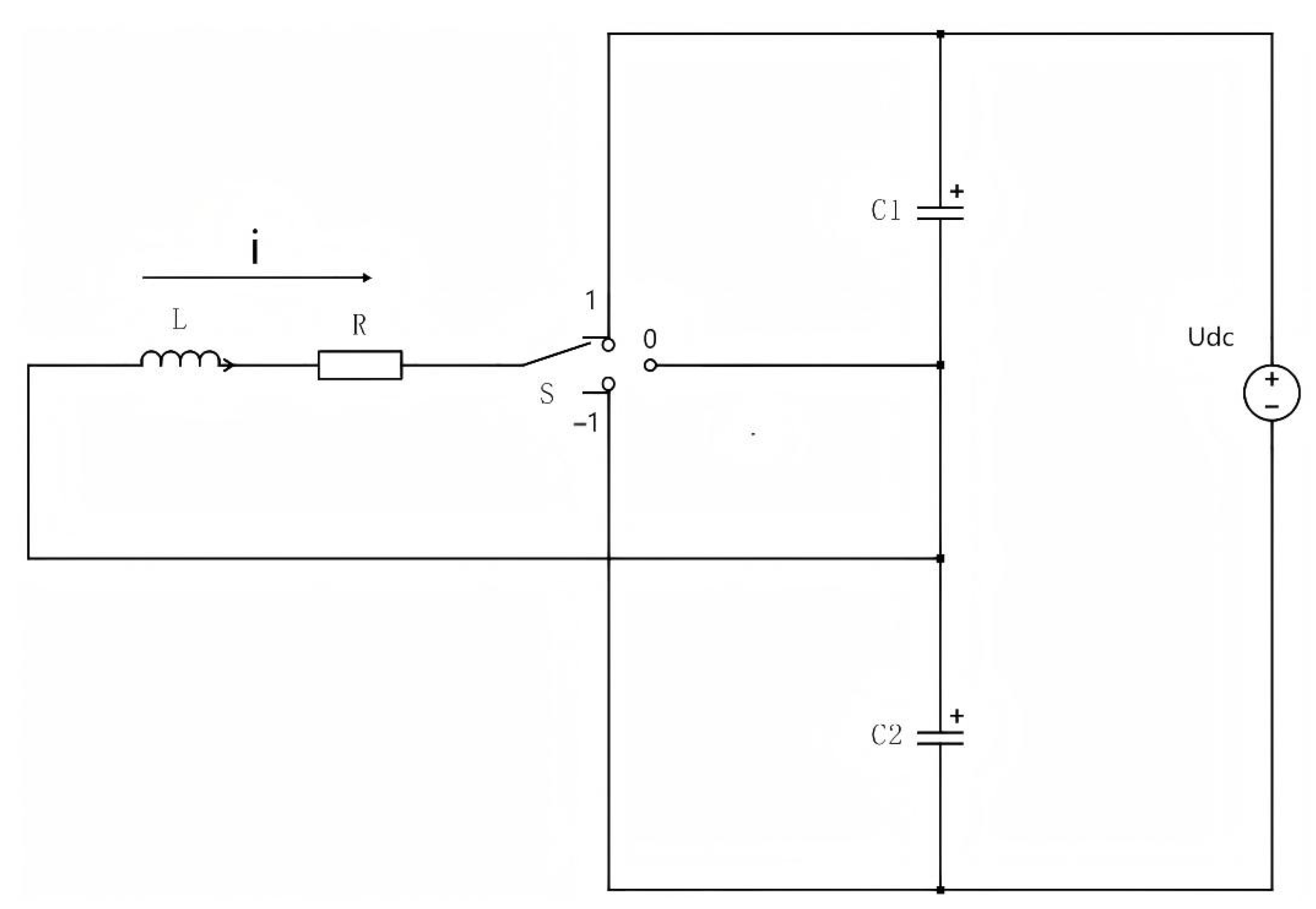
- Uneven voltage distribution in DC-link capacitors, resulting in excessive voltage stress on power devices (e.g., MOSFETs or diodes) beyond their rated thresholds. This accelerates device degradation and risks dielectric breakdown failures;
- Output voltage distortion, which elevates total harmonic distortion (THD) and compromises power quality;
- Additional charge–discharge losses, degrading overall system efficiency.
3. Results and Discussion
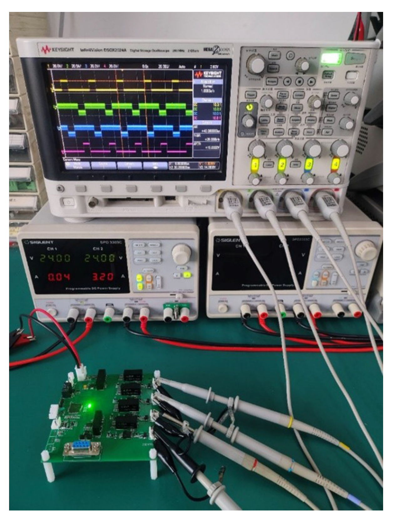
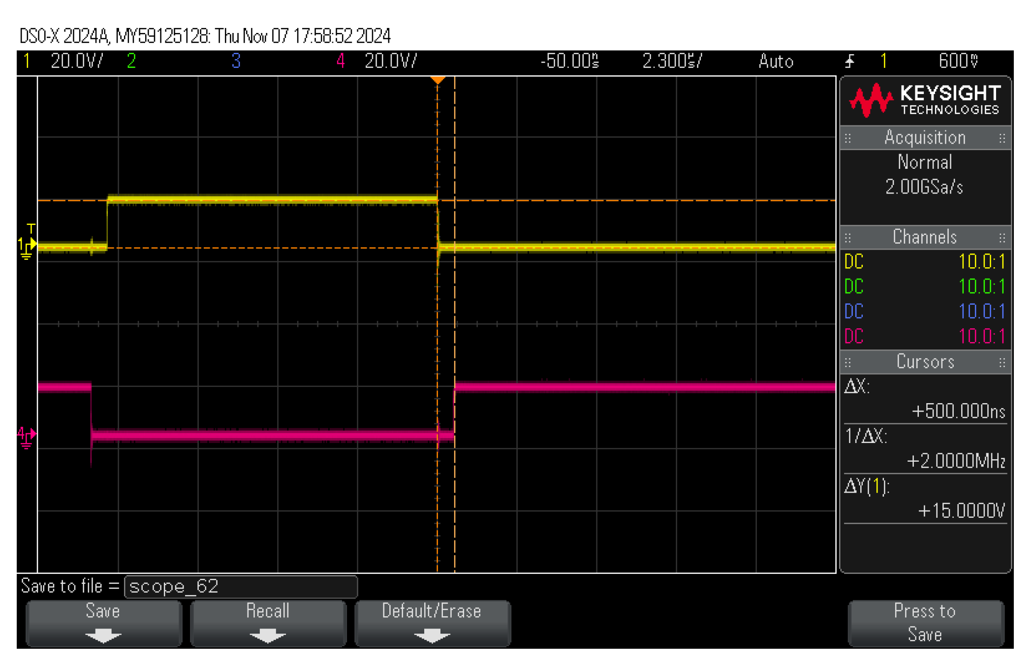
3.1. Analysis of PWM Drive Signal Source
3.2. Analysis of Three-Level Voltage Signal
3.3. Analysis of Three-Level Current Signal
3.4. Analysis of Transformer Output Signal
4. Conclusions
- High device cost: SiC devices are more expensive to manufacture compared to traditional silicon-based components, resulting in higher overall system costs. Although technological advancements and mass production have reduced costs, SiC-based solutions remain more expensive than their silicon counterparts;
- Complex control strategy: the three-level topology requires a more sophisticated control strategy to ensure precise switching device operation and output voltage stability. This complexity increases the difficulty of control system design.
Author Contributions
Funding
Data Availability Statement
Conflicts of Interest
References
- Wang, Z.M.; Fan, W.Y.; Xie, F.X.; Ye, C.X. An 8kW LLC resonant converter in plasma power supplybased on SiC power devices for efficiency improvement. Circuit World 2019, 45, 181–188. [Google Scholar]
- Rong, J.; Ai, X.; Li, Y.; Ren, D. Research on the structure and control strategy of a novel power electronic transformer for AC/DC hybrid distribution network. Appl. Sci. 2019, 9, 727. [Google Scholar] [CrossRef]
- Safder, M.U.; Rizvi, S.T.; Meng, Y.; Javed, M.Y.; Jaffery, M.H.; Hassan, M.S. Low-frequency ac power transmission and distribution for subsea application using hexverter. Electronics 2020, 9, 61. [Google Scholar] [CrossRef]
- Jiang, D.Z.; Zhang, Z.H. Control strategy of three-phase H-bridge cascaded static synchronous compensator. High-Volt. Technol. 2011, 37, 2024–2032. [Google Scholar]
- Nabae, A.; Takahashi, I.; Akagi, H. A new neutral-point-clamped PWM inverter. IEEE Trans. Ind. Appl. 1981, 5, 518–523. [Google Scholar]
- Chang, F.; Zhao, L.P.; Feng, J.B. Application of five-level AC-DC converter in through-phase power supply. Power Syst. Its Self J. Anim. Chem. 2015, 27, 26–31. [Google Scholar]
- Beig, A.R.; Dekka, A. Experimental verification of multilevel inverter-based standalone power supply for low-voltage and low-power applications. IET Power Electron. 2012, 5, 635–643. [Google Scholar]
- Sadikin, M.; Senjyu, T.; Yona, A. DC–DC type high-frequency link DC for improved power quality of cascaded multilevel inverter. Int. J. Emerg. Electr. Power Syst. 2013, 14, 333–340. [Google Scholar] [CrossRef]
- Han, D.; Li, S.; Lee, W.; Sarlioglu, B. Adoption of wide bandgap technology in hybrid/electric vehicles-opportdeviceies and challenges. In Proceedings of the 2017 IEEE Transportation Electrification Conference and Expo (ITEC), Chicago, IL, USA, 22 June 2017; IEEE: New York, NY, USA, 2017; pp. 561–566. [Google Scholar]
- Ma, B. Comparative study on the performance of inverter systems based on Si and SiC devices. Electr. Drives 2017, 47, 3–6. [Google Scholar]
- Sheng, Z.; Dong, Z.Z.; Wu, X.K. Review and outlook of key technologies for silicon carbide power device packaging. Chin. J. Electr. Eng. 2019, 39, 5576–5584. [Google Scholar]
- Krisna, T.N.; Sathishkumar, P.; Himasree, P.; Punnoose, D.; Raghavendra, K.V.; Himanshu; Naresh, B.; Rana, R.A.; Kim, H.J. 4T analog MOS control-high-voltage high-frequency (HVHF) plasma switching power supply for water purification in industrial applications. Electronics 2018, 7, 245. [Google Scholar] [CrossRef]
- Neretti, G.; Ricco, M. Self-tuning high-voltage and high-frequency sinusoidal power supply for dielectric barrier discharge plasma generation. Electronics 2019, 8, 1137. [Google Scholar] [CrossRef]
- Cai, X.W.; Fu, Z.H.; Xie, H.S.; Xue, J.X.; Ding, D.H.; Ou, N.; Zhou, G. Resonant Power Supply for Plasma Cleaning Based on Fuzzy Logic Power Tracking. Appl. Sci. 2022, 12, 4681. [Google Scholar] [CrossRef]
- Krupski, P.; Stryczewska, H.D. The Investigation of the Properties of High-voltage Transformer in Nonthermal Plasma Pulse Power Supply. In Proceedings of the 2018 14th Selected Issues of Electrical Engineering and Electronics (WZEE), Szczecin, Poland, 19 November 2018; IEEE: New York, NY, USA, 2018; pp. 1–4. [Google Scholar]
- Xun, Q.; Xun, B.; Li, Z.; Wang, P.; Cai, Z. Application of SiC power electronic devices in secondary power source for aircraft. Renew. Sustain. Energy Rev. 2017, 70, 1336–1342. [Google Scholar]
- Han, G.J.; Deng, J.L.; Xu, D. Research on high-frequency and high-voltage switching power supply for electrostatic precipitator. Appl. Mech. Mater. 2013, 241, 653–656. [Google Scholar] [CrossRef]
- Zhao, Z.Q.; Wang, Z. Designing and Simulation Testing of Kilowatt Switching Power Supply Transformer. Adv. Mater. Res. 2012, 490, 1332–1336. [Google Scholar]
- Li, P. Design and Research of Medical Plasma Power Supply; Chang’an University: Xi’an, China, 2022. [Google Scholar] [CrossRef]
- Zhu, W.; Wu, S.B.; Lu, H.Y.; Hong, X.; Yu, J.J.; Zhang, Y. The design of high-voltage direct current power supply for the electrical fast transient pulse/burst generator. Appl. Mech. Mater. 2014, 494, 1452–1456. [Google Scholar]
- Sato, K.; Sato, T.; Sonehara, M.; Takeuchi, H. Low permeability composite magnetic core transformer with high coupling coefficient and its application to PFM controlled quasi-resonant mode flyback-type DC-DC converter. J. Magn. Soc. Jpn. 2017, 41, 132–139. [Google Scholar]
- Seo, H.; Kwon, H.; Kwon, Y.; Kim, K.; Choi, S.; Kim, H.; Jang, K. Fast number theoretic transform for ring-LWE on 8-bit AVR embedded processor. Sensors 2020, 20, 2039. [Google Scholar] [CrossRef]
- Li, G.J. Design of Intelligent Control of DC Motor. Appl. Mech. Mater. 2013, 313, 427–431. [Google Scholar]
- Bai, X.F.; Li, P.; Li, H.; Song, X.N.; Wang, C.W. The Vertical Axis Wind Power Controller Design. Adv. Mater. Res. 2013, 816, 989–992. [Google Scholar]
- Yang, G.; Fu, C.; Yi, H.; Chai, C.; Huang, B.; Hao, S.; Chen, Z. Direct power control of three-level NPC grid-connected system combined with fault-tolerant technology. Microelectron. Reliab. 2018, 88, 1057–1062. [Google Scholar]
- Rukin, S.N. Pulsed power technology based on semiconductor opening switches: A review. Rev. Sci. Instrum. 2020, 91, 011501. [Google Scholar] [CrossRef]
- Syed, A.; Sandipamu, T.K.; Suan, F.T. High-efficiency neutral-point-clamped transformerless MOSFET inverter for photovoltaic applications. IET Power Electron. 2018, 11, 246–252. [Google Scholar]
- Lu, T.; Zhao, Z.; Yu, H.; Ji, S.; Yuan, L.; He, F. Parameter design of a three-level converter based on series-connected HV-IGBTs. IEEE Trans. Ind. Appl. 2014, 50, 3943–3954. [Google Scholar]
- Rajalakshmi, S.; Rangarajan, P. Investigation of modified multilevel inverter topology for PV system. Microprocess. Microsyst. 2019, 71, 102870. [Google Scholar]
- Li, M.; Jia, K.; Bi, T.; Wang, C.; Zhu, R.; Yang, Q. Full-current-based directional pilot protection for VSC-DC distribution systems. IET Gener. Transm. Distrib. 2019, 13, 3713–3724. [Google Scholar]
- Islam, M.; Mekhilef, S.; Hasan, M. Single phase transformerless inverter topologies for grid-tied photovoltaic system: A review. Renew. Sustain. Energy Rev. 2015, 45, 69–86. [Google Scholar]
- Chen, H.C.; Lin, R.S. Design of an H-bridge driver without dead-time generation using gate bias. IEICE Electron. Express 2013, 10, 20130656. [Google Scholar]
- Liu, G.; Wang, K.; Qu, C.; Liu, S.; Jia, Q.; Li, Y. Phase-shift full bridge power supply based on SiC devices. J. Eng. 2018, 2018, 453–460. [Google Scholar]
- Lyu, J.; Hu, W.; Wu, F.; Yao, K.; Wu, J. Three-level saddle space vector pulse width modulation strategy based on two-level space vector pulse width modulation for neutral-point-clamped three-level inverters. IET Power Electron. 2016, 9, 874–882. [Google Scholar] [CrossRef]
- Choi, U.M.; Lee, K.B. Space vector modulation strategy for neutral-point voltage balancing in three-level inverter systems. IET Power Electron. 2013, 6, 1390–1398. [Google Scholar] [CrossRef]
- Xu, S.Z.; He, F.Y. Improvement of High-Power Three-Level Explosion-Proof Inverters Using Soft Switching Control Based on Optimized Power-Loss Algorithm. J. Electr. Comput. Eng. 2015, 2015, 571209. [Google Scholar] [CrossRef][Green Version]
- Orfanoudakis, G.I.; Yuratich, M.A.; Sharkh, S.M. Analysis of dc-link capacitor current in three-level neutral point clamped and cascaded H-bridge inverters. IET Power Electron. 2013, 6, 1376–1389. [Google Scholar] [CrossRef]
- König, N.; Nienhaus, M. A solution to ambiguities in position estimation for solenoid actuators by exploiting eddy current variations. Sensors 2020, 20, 3441. [Google Scholar] [CrossRef]
- Rana, N.; Kumar, M.; Ghosh, A.; Banerjee, S. A novel interleaved tri-state boost converter with lower ripple and improved dynamic response. IEEE Trans. Ind. Electron. 2017, 65, 5456–5465. [Google Scholar] [CrossRef]
- Phankong, N.; Yuktanon, N.; Bhumkittipich, K. Three-level back-to-back converter simulation for wind turbine energy source. Energy Procedia 2013, 34, 449–458. [Google Scholar] [CrossRef]
- Dong, R.; Liu, S.; Liang, G. Research on control parameters for voltage source inverter output controllers of micro-grids based on the fruit fly optimization algorithm. Appl. Sci. 2019, 9, 1327. [Google Scholar] [CrossRef]
- Hu, X.; Nan, G. Research of Full Digit Single-phase Inversion Power Supply Based on DSP. Energy Procedia 2012, 17, 580–587. [Google Scholar] [CrossRef][Green Version]
- Liang, C.; Tian, E.; Pang, B.; Li, J.; Yang, Y. Model Predictive Control of LCL Three-level Photovoltaic Grid-connected Inverter. In IOP Conference Series: Earth and Environmental Science; IOP Publishing: Bristol, UK, 2018; Volume 153, p. 042023. [Google Scholar]
- Liu, D.; Deng, F.; Chen, Z. Five-level active-neutral-point-clamped DC/DC converter for medium-voltage DC grids. IEEE Trans. Power Electron. 2016, 32, 3402–3412. [Google Scholar] [CrossRef]
- Erickson, R.W.; Maksimovic, D. Fundamentals of Power Electronics; Springer Science & Business Media: Berlin/Heidelberg, Germany, 2007. [Google Scholar]
- Chen, G.; Zhu, M.; Cai, X. Parameter optimization of the LC filters based on multiple impact factors for cascaded H-bridge dynamic voltage restorers. J. Power Electron. 2014, 14, 165–174. [Google Scholar] [CrossRef]
- Mohan, N.; Undeland, T.M.; Robbins, W.P. Power Electronics: Converters, Applications, and Design; John Wiley & Sons: Hoboken, NJ, USA, 2003. [Google Scholar]






| Research Institution | Method | Frequency | Output Voltage | Power |
|---|---|---|---|---|
| Pusan National University | Full-bridge inverter utilizing silicon-based MOSFETs | 25 kHz | 10 kV | 5 kW |
| University of Bologna | Half-bridge inverter utilizing silicon-based MOSFETs | 10–60 kHz | 20 kV | 200 W |
| Longyan University | Phase-shifted full-bridge inverter | 20–50 kHz | 3.2 kV | 500–1000 W |
| Lublin University of Technology | Half-bridge inverter utilizing IGBTs | 10–25 kHz | 14 kV | / |
| Parameters | Peak-to-Peak Specifications |
|---|---|
| 45 A | |
| 320 V | |
| 25 kV | |
| 15 kW | |
| 25 kHz |
| Switching State | Q1 | Q2 | Q3 | Q4 | |
|---|---|---|---|---|---|
| P | 1 | 1 | 0 | 0 | |
| 0 | 0 | 1 | 1 | 0 | 0 |
| N | 0 | 0 | 1 | 1 | |
| 0 | 0 | 1 | 1 | 0 | 0 |
| Category | Principle | Algorithm Complexity | Application Scenarios |
|---|---|---|---|
| Symmetric complementary PWM | Neutral-point current charge/discharge magnitudes are balanced between positive/negative half-cycles. | Low | Simple topologies |
| SPWM (sinusoidal PWM) | PWM waveforms equivalent to sinusoidal signals are generated by comparing sinusoidal reference waves with triangular carrier waves. | Moderate | Universal applications |
| SVPWM (space vector PWM) | Neutral-point balance is achieved by controlling the duty cycles of redundant small vectors. | High | High-precision and highly dynamic responses |
| Days | Frequency | Bus Voltage | Bus Current | Power | Temperature |
|---|---|---|---|---|---|
| 2 | 25 kHz | 311.9 V | 42.9 A | 13.38 kW | 27.9 °C |
| 4 | 25 kHz | 312.1 V | 42.7 A | 13.33 kW | 28.1 °C |
| 6 | 25 kHz | 311.2 V | 43.1 A | 13.41 kW | 27.8 °C |
| 8 | 25 kHz | 312.0 V | 43.0 A | 13.42 kW | 28.0 °C |
Disclaimer/Publisher’s Note: The statements, opinions and data contained in all publications are solely those of the individual author(s) and contributor(s) and not of MDPI and/or the editor(s). MDPI and/or the editor(s) disclaim responsibility for any injury to people or property resulting from any ideas, methods, instructions or products referred to in the content. |
© 2025 by the authors. Licensee MDPI, Basel, Switzerland. This article is an open access article distributed under the terms and conditions of the Creative Commons Attribution (CC BY) license (https://creativecommons.org/licenses/by/4.0/).
Share and Cite
Cai, K.; Xiao, J.; Yang, Z.; Hu, R. Three-Level All-SiC High-Frequency High-Voltage Plasma Power Supply System. Energies 2025, 18, 1617. https://doi.org/10.3390/en18071617
Cai K, Xiao J, Yang Z, Hu R. Three-Level All-SiC High-Frequency High-Voltage Plasma Power Supply System. Energies. 2025; 18(7):1617. https://doi.org/10.3390/en18071617
Chicago/Turabian StyleCai, Kaida, Jing Xiao, Zhe Yang, and Ranghao Hu. 2025. "Three-Level All-SiC High-Frequency High-Voltage Plasma Power Supply System" Energies 18, no. 7: 1617. https://doi.org/10.3390/en18071617
APA StyleCai, K., Xiao, J., Yang, Z., & Hu, R. (2025). Three-Level All-SiC High-Frequency High-Voltage Plasma Power Supply System. Energies, 18(7), 1617. https://doi.org/10.3390/en18071617


