1. Introduction
Heat dissipation devices, such as heat sinks [
1,
2,
3,
4,
5,
6], heat pipes [
7,
8,
9,
10], and heat spreaders [
11,
12,
13,
14] are essential in many applications to prevent component failure. The rapid advancement of technology and a continual increase in power density drive the need for lighter and more compact heat dissipation devices. Heat sinks are a form of heat dissipation device that transfers the heat generated from a device into either air or fluid, typically through large surface areas. Heat pipes and thermosyphons are thermal transfer devices with high heat transfer capabilities through the phase-change of a working fluid.
Heat sinks have different categories: passive, semi-active, active, liquid-cooled cold plates, and phase change recirculating systems with different heights and load limitations [
1]. There are also different types of heat sinks: stampings, extrusions, bonded/fabricated fins, castings, and folded fins [
1]. Each type of heat sink has its own characteristics. Many studies [
2] have been conducted on optimizing the shape, type, channel size, and material of heat sinks. Mousavi et al. [
3] investigated the influence of staggering, interrupting, and capping the fins on a heat sink with natural convection and radiation heat transfer. Bhattacharya and coauthors [
4] found improved performance with a finned-metal foam heat sink compared to a longitudinal or full-metal foam heat sink. Rubio-Jimenez et al. [
5] used variable fin density to minimize the increase in temperature of the coolant and create a more consistent integrated circuit chip temperature. Yang and coauthors [
6] found improved thermal performance by using un-uniform fin heights and increasing the fin height near the center of the heat sink.
Heat sinks work very well transporting heat, but extreme temperatures will limit their dissipation abilities; if a heat sink’s fins are too fragile or damaged, heat will not dissipate [
7]. Therefore, heat sinks and heat pipes together are beneficial. Heat pipes allow for flexibility when there are contact areas with heat sources and heat sinks [
7,
8]. Heat pipes are typically used in three ways: temperature equilibrium, temperature control, and separation of a heat source and sink [
7]. They are heavily used in many computer systems, due to the high power requirements leading to high heat emission; these pipes act as a cooling system [
7]. To use the heat pipe with the electronic system, there are two options: mounting the system directly onto the heat pipe or mounting it to a plate that has heat pipes inside of it [
7]. There are different types of heat pipes, such as mini/micro heat pipes [
9], polymer-based small heat pipes [
9], and pulsing heat pipes [
10]. Micro heat pipes (MHPs) can be made by using micromachining technology and are tested to ensure that the pipe can act as a thermal heat spreader [
7].
Heat spreaders [
11,
12,
13,
14] are used to spread heat from a hot spot across a heat sink base and lower the thermal spreading resistance. Hsieh et al. [
11] investigated a vapor chamber heat spreader and showed a thermal spreading resistance of 0.2 °C/W. Tsai and coauthors [
12] investigated the influence of orientation and gravity on the thermal performance of a vapor chamber heat spreader. Li et al. [
13] incorporated a novel thin flat heat pipe into a heat spreader and Jaworski [
14] used phase change material as a heat spreader.
Some studies [
15,
16] have investigated adding a heat spreader and/or heat pipe to a finned heat sink. Kumar and coauthors [
15] used a heat sink, phase change material, and a heat pipe and showed a 3 °C lower heater surface temperature. Muneeshwaran et al. [
16] used a vapor chamber, finned heat sink, and heat pipe to reduce the thermal resistance by 55% compared to the finned heat sink alone. Recently, Dhanalakota and coauthors [
17] integrated a flat thermosyphon with hollow fins and showed a reduction in thermal resistance, surface temperature, and weight.
A continual increase in power density and the swift advancement of technology drive the need for lightweight and more dense heat dissipation devices. As shown above, there is research on the separate components or attaching the components together of a heat spreader, heat pipe, and finned heat sink, but there is limited research on the integration of heat spreader, heat pipe, and a finned heat sink as one component. The purpose of this research was to determine whether a hollow fluid-filled (FF) heat sink was more effective than solid heat sinks for heat dissipation. A copper FF heat sink and an aluminum FF heat sink were experimentally tested along with solid heat sink versions. The thermal performance of the four heat sinks was compared to each other and to previous research.
2. Materials and Methods
2.1. Heat Sinks
The four heat sinks were constructed as 4 × 4 fin arrays (
Figure 1). Two heat sinks were solid metal: one solid copper and one solid aluminum. The other two heat sinks were hollow. The thermal properties of the copper and aluminum (aluminum alloy 6061) are shown in
Table 1. Copper and aluminum were chosen since they are the most used materials for heat sinks.
The fabrication process for the hollow heat sinks consisted of three distinct pieces: a bottom plate, a hollow base and fins, and a fill tube. The copper bottom plate and fill tube (inserted at the top of one fin) were soldered (using 60% tin, 40% lead solder blend) to the hollow copper base and fins. On the hollow aluminum heat sink, the bottom plate and fill tube were welded (using gas tungsten arc welding) and epoxied (using Loctite E-120hp from Henkel Corporation, Rocky Hill, CT, USA), respectively. It should be noted that the hollow base had a wall thickness of 1.25 mm, and the hollow fins had an internal bore diameter of 4.6 mm.
To ensure vacuum sealing, each hollow heat sink was tested for leaks before fluid filling. A vacuum pump was used to remove air, and a pressure sensor was employed to confirm a stable internal vacuum. The hollow copper and aluminum heat sinks were filled with fluid with a fill volume of 50% based on prior research findings that suggest optimal fill volumes for heat pipes range between 30 and 40% [
18,
19] and 65% for thermosyphons [
20]. Water was selected for the hollow copper heat sink, while acetone was chosen for the hollow aluminum heat sink to prevent corrosion and outgassing. Other compatible fluids, such as methanol for copper and ammonia for aluminum heat pipes [
7], were considered but not selected for this study.
Table 1.
Thermophysical properties.
Table 1.
Thermophysical properties.
| Property | Units | Copper 1 | Aluminum 2 |
|---|
| Density | kg/m3 | 8933 | 2702 |
| Specific Heat | J/kg-K | 385 | 934 |
| Thermal Conductivity | W/m-K | 397 | 195 |
2.2. Experimental Testing Apparatus
The experimental testing apparatus to evaluate and assess the performance of a heat pipe integrated with a conventical heat sink included a wind tunnel with a fan, an aluminum heater block, Arduino microcontrollers, and a heat source (
Figure 2a). The wind tunnel had a 77.3 mm inner diameter and a length of ten times the diameter to ensure fully developed flow. To measure air velocity, a thermopile-based air velocity sensor was located at the exit plane of the wind tunnel, 6.35 mm from the wall, with an accuracy of ±0.36 m/s. The wind tunnel fan speed was controlled via an external power supply to maintain target air velocities.
Power was supplied to the bottom of the heating block and applied a heat of 20 W, 40 W, and 60 W to the base of the heat sink. Four thermistor sensors, with an accuracy of ±0.25 °C, were used to measure temperature at 6.35 mm and 57.2 mm from the top of the aluminum heater block, at the base of the fins, and the tip of a fin (
Figure 2b). The fin base and fin tip temperature sensors were applied with thermal paste and conductive copper or aluminum tape for their respective heat sinks. To ensure consistent thermal contact between the heater block and each heat sink, the same quantity of thermal paste was applied between the top of the heater block and the bottom of the heat sink before each test.
Data acquisition was performed using a laptop running an in-house Python-based system. Two Arduinos collected and transmitted data via serial communication: one measured the thermistors, while the other measured the air velocity. The Python version 3.10 software logged temperature and velocity measurements at a sampling rate of 1 Hz and continuously applied a 10 s moving average to smooth short-term fluctuations. The heater power was recorded in the software before and after each experiment.
2.3. Experimental Testing Procedure
Each heat sink was tested at nine different operating conditions with three distinct heat inputs and corresponding velocities (
Table 2). Each experimental run consisted of preparation, execution, and post-experiment processing.
During preparation, the heat sink was installed on the heater block, ensuring secure thermal contact. The thermistor sensors were checked for proper placement and adhesion and the wind tunnel fan was adjusted to the target air velocity. The heater block was powered on, adjusted, and documented and real-time temperature monitoring began. During execution, each operating condition was conducted for 3600 s to reach a steady state, defined as an average change in heater block temperature of less than 0.002 K/s. Once a steady state was achieved, sensor data were recorded for five minutes. The average temperature change during steady-state data collection remained below 0.006 K/s for all test conditions, with most cases below 0.002 K/s. Data were collected at 1 Hz, with a 10 s moving average applied to temperature and air velocity measurements to smooth fluctuations. During post-experiment processing, the heat sink was removed and inspected for leaks or thermal paste degradation. The recorded data were reviewed for anomalies before further analysis.
2.4. Theory
The heat transfer rate (
q) into the heat sinks was calculated using Fourier’s law (Equation (1)) and the two measured temperatures (
T) along the heater block and the distance between the temperature sensors. Equation (1) neglects heat loss through the sides of the heater block since the heater block was well insulated. The total heat transfer into the heat sinks is equal to the heat loss due to convection from the sides of the heat sink base, the top surface of the heat sink base, and the fins (Equation (2)). Newton’s law of cooling can be used to describe the three convection heat losses (Equation (3)).
The total thermal resistance of each heat sink was determined from the heat transfer rate and the difference between the heater top surface and ambient temperature (Equation (4)). This resistance includes the thermal interface resistance between the top surface of the heater block and the bottom surface of the heat sink. The top surface of the heater was extrapolated assuming a linear temperature distribution along the heater block from the two measured temperatures. The thermal resistance for the fin array, the sides of the heat sink base, and the top surface of the heat sink base were calculated using Equations (5)–(7), respectively. Additionally, to account for the significant weight difference between the four heat sinks, a mass-based total thermal resistance was calculated using Equation (8). Therefore, a lighter-weight heat sink with the same thermal resistance will have a lower mass-based thermal resistance. A thermal resistance comparison between the current study and previous research on heat pipes, vapor chambers, and heat sinks was conducted. To normalize the total thermal resistance from various studies, the thermal resistance per unit area was utilized (Equation (9)). The area was the bottom surface area of the component (heat pipe, heat sink, vapor chamber, etc.), not the surface area of the heater. The air velocity was normalized using the Reynold’s number, Equation (10), of the air based on the fin length.
3. Results
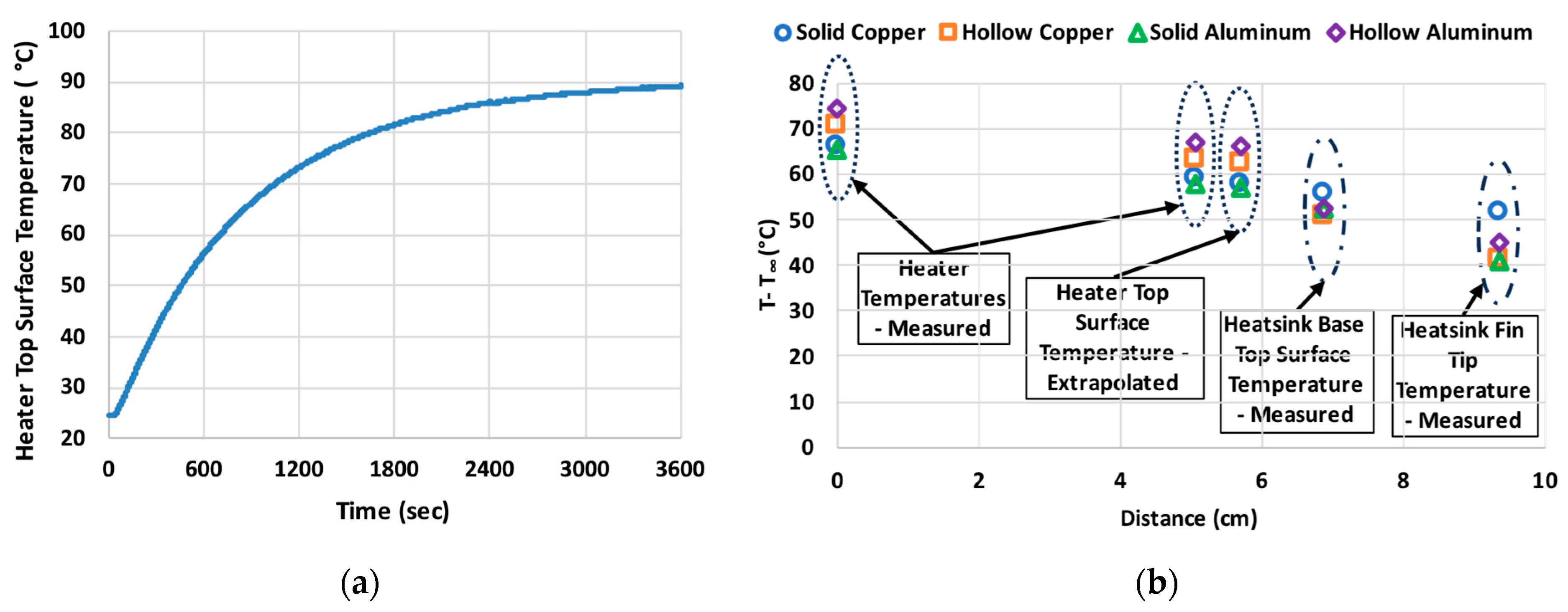
The transient tests reached a steady state after 1 h when the average change in the heater block temperature was less than 0.002 K/s. As an example,
Figure 3a shows the transient test for the top surface of the heater for the hollow copper heat sink at a heat transfer rate of 60 W and air velocity of 5 m/s. It should be noted that calculated thermal resistances from Equations (4)–(8) changed by less than 1% after 50 min. The measured and extrapolated steady-state temperatures for all the heat sinks at the heat transfer rate and air velocity of 60 W and 5 m/s, respectively, are shown in
Figure 3b. The two measured heater block temperatures, extrapolated top heater surface temperature, measured fin base temperature, and measured fin tip temperature are labeled in the figure. A distance of zero corresponds to the location of the measured heater block temperature closest to the heaters. The two measured heater block temperatures were used in Equation (1) to calculate the change in temperature with distance for Fourier’s law. The same two temperatures were used to extrapolate the temperature at the top surface of the heater block from Equation (2). The fin base and fin tip temperatures were directly measured and labeled in
Figure 3b.
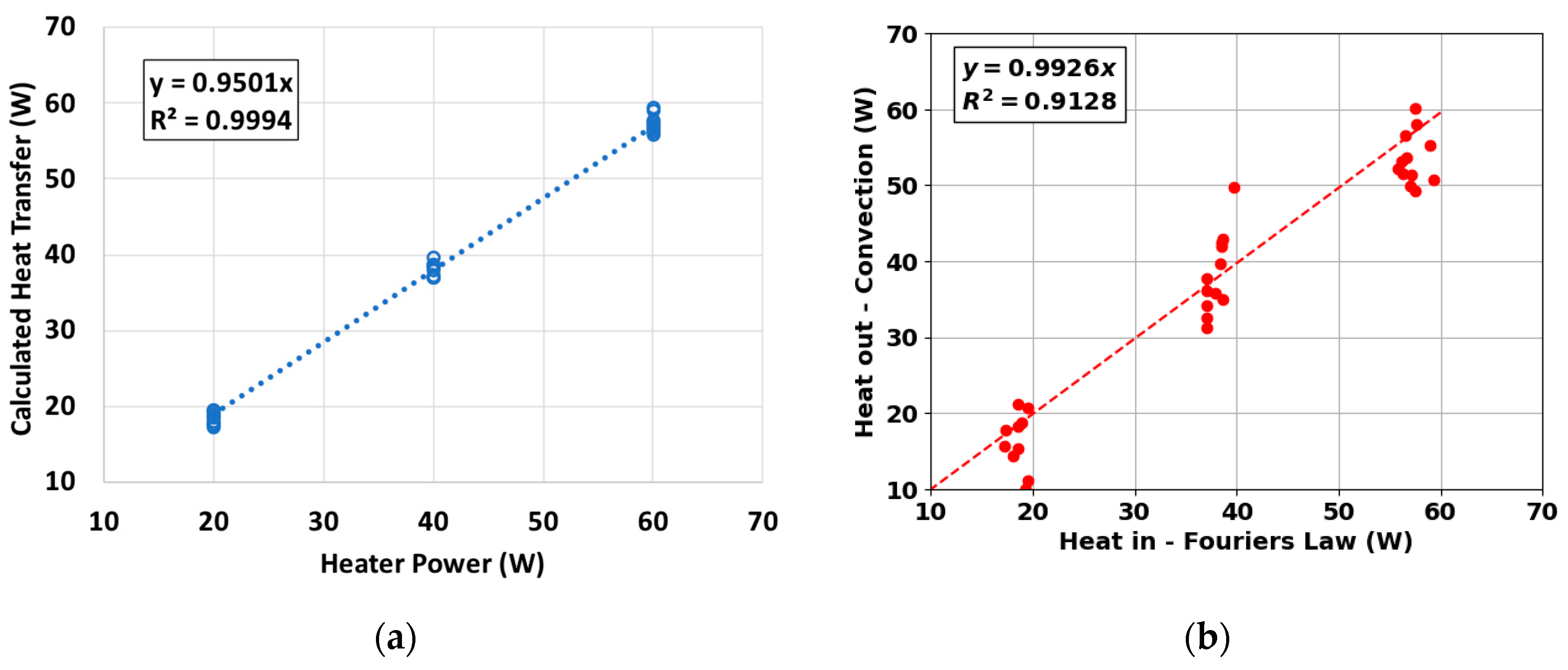
A comparison between the heater power, from the measured voltage and current, to the calculated heat transfer, using Equation (1), was performed to verify the operation of the test apparatus. As shown in
Figure 4a, only a five percent heat loss occurred due to the insulation below and around the heater block. In addition, the heat transfer calculated from Fourier’s law (Equation (1)) was verified by calculating the convection heat transfer (Equation (3)) leaving the heat sinks by using the accepted correlations for the convection coefficients [
21]. For the sides of the fins and the sides of the base, the accepted correlations for flow along a constant surface temperature flat plate were used [
21]. For the tip of the fins and the top surface of the base, the accepted correlations for flow perpendicular to a thin plate were used [
21]. For the experiments with zero air velocity, natural convection correlations for a vertical or horizontal flat plate were used to find the convection coefficient [
21]. Overall, the heat transfer into the heat sinks, from Equation (1), agreed within 1% of the heat transfer out of the heat sinks, from Equation (3), with an r-squared value of 0.91 (
Figure 4b). While there was some variability, this was deemed acceptable due to the accuracy of the correlations and approximation of the surfaces as standalone flat plates.
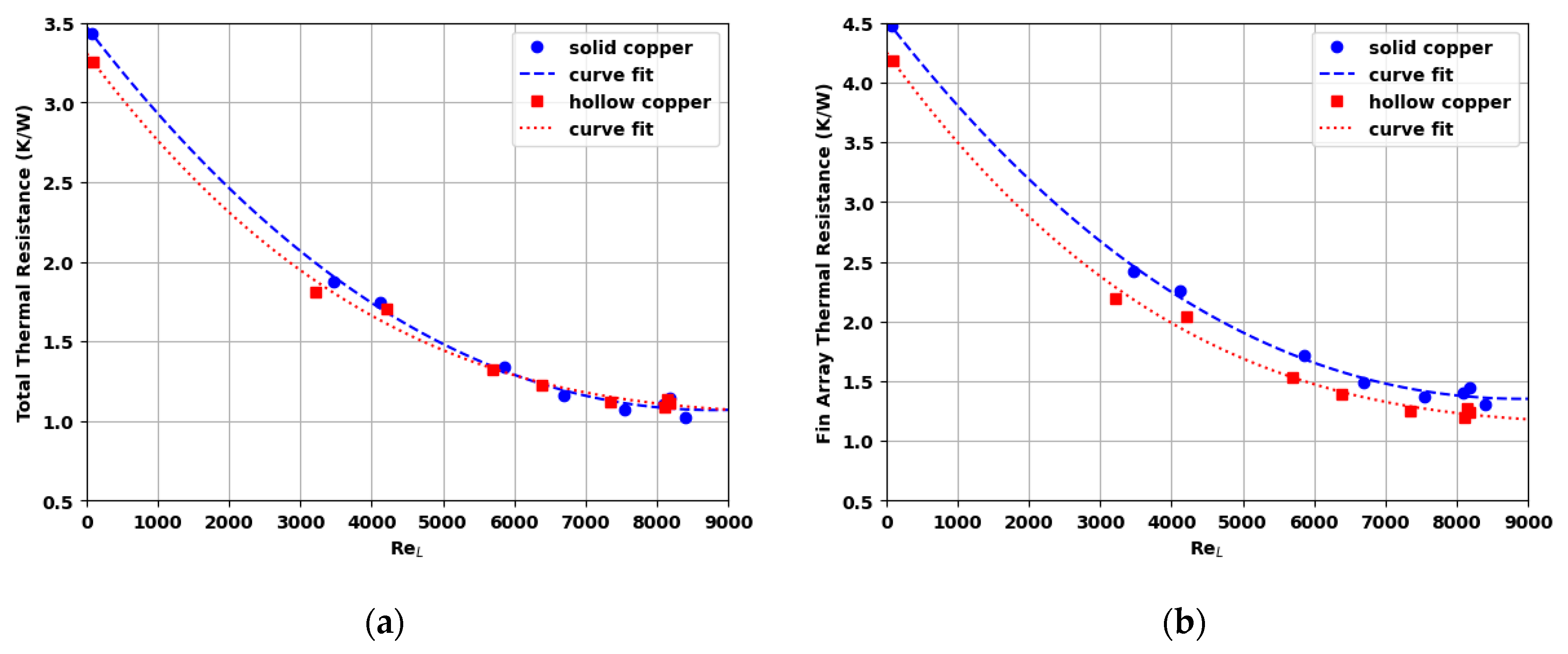
At a heat rate of 20 W, the total thermal resistances (Equation (4)) decreased with the FF copper heat sink by 1 to 5% compared to the solid copper heat sink (
Figure 5a). The FF copper heat sink changed the total thermal resistance by −3 to 1% compared to the solid copper heat sink at a heat rate of 40 W. At the highest heat rate of 60 W, the total thermal resistance increased by 4 to 6% with the FF copper heat sink compared to the solid copper heat sink. The mean of all nine operating points for the total thermal resistance of the FF copper heat sink was within 0.4% of the solid version. While the total thermal resistance increased or decreased depending on the operating point, the thermal resistance for the fin array (Equation (5)) decreased at all operating points for the FF copper heat sink compared to the solid copper heat sink (
Figure 5b). The decrease in fin array thermal resistance was 6 to 12% with an average decrease of 9%. It should be noted that all heat sinks were tested in a horizontal position. Their thermal resistances would differ if tested in a vertical or inclined position.
The total thermal resistance (Equation (4)) for the FF aluminum heat sink increased (
Figure 6a) at every operating point compared to the solid aluminum heat sink except at a heat rate of 20 W with still air (air velocity of 0 m/s). The change in total thermal resistance varied from a decrease of 0.2% to an increase of 20% for the FF compared to the solid aluminum heat sink with an average increase of 11%. The fin array thermal resistance (Equation (5)) decreased at all operating points for the aluminum FF heat sink compared to the solid aluminum heat sink (
Figure 6b), except for the operating condition of 60 W and air velocity of 5 m/s. The fin array thermal resistance varied from an increase of 2% to a decrease of 7% with an average decrease of 2%.
4. Discussion
As shown in
Figure 5b and
Figure 6b, the fin array thermal resistance (Equation (3)) decreased for the FF heat sinks compared to their solid versions. In addition, the fin array thermal resistance for the FF copper or FF aluminum heat sink was less than the solid copper or aluminum heat sinks, with the FF copper heat sink having the lowest thermal resistance for the fin array (
Figure 7a).
Figure 7b shows the convection thermal resistance from the side of the heat sink base. A similar trend was seen for the convection from the top surface of the heat sink base with a lower thermal resistance for the hollow heat sinks. The total thermal resistance involved heat transfer paths through the sides of the heat sink base, the top surface of the heat sink base, and the fin array (Equation (2)). If the hollow heat sinks had lower thermal resistances for the fin array and from convection on the heat sink base, then the varying total thermal resistance from the FF heat sinks can be attributed to an increase in thermal resistance through the inside of the base of the heat sink. Decreasing the height of the base should decrease the base thermal resistance. This increase in base thermal resistance may be due to unfavorable fluid motion within the base volume of the heat sink.
As shown in
Table 1, copper has 2.1 times the thermal conductivity of aluminum, but 3.3 times the density. The FF copper and aluminum heat sinks had a reduction in mass of 40% and 43% to their solid versions. In addition, the FF aluminum heat sink had an 82% reduction in mass compared to the solid copper heat sink. On average, the total thermal resistance of the FF aluminum heat sink increased by 8% compared to the solid copper heat sink. To incorporate the thermal resistance and mass of the heat sink, a mass-based thermal resistance was defined (Equation (8)).
Figure 8 shows the mass-based thermal resistance for all the heat sinks. The FF aluminum heat sink had the lowest mass-based thermal resistance and was, on average, 77% lower than the solid copper heat sink. FF heat sinks can provide a lightweight option for industries, such as space, automotive, and military applications.
The minimum thermal resistance per unit area values (Equation (9)) from the current study are compared to those from previous studies in
Table 3, providing insights into the effectiveness of different thermal management systems. A flat thermosyphon and a heat pipe with chilled water cooling from prior studies significantly outperformed all air-cooled solutions highlighting the advantage of liquid-cooled condensers in reducing thermal resistance. Among air-cooled solutions, the CPU heat sink [
23] with two heat pipes (14.2 K-cm
2/W) exhibited lower thermal resistance than the FF heat sink designs in the current study. This is attributed to its higher fin density which increases the convection surface area and enhances heat dissipation.
Table 3.
Thermal resistance per unit area comparison with previous research.
Table 3.
Thermal resistance per unit area comparison with previous research.
| Description | Resistance
(K-cm2/W) | Material | Working Fluid | Fill Ratio | Condenser Cooling |
|---|
| Single heat pipe [18] | 6.4 | Copper | Water | 30% | Chilled Water |
| Vapor chamber heat spreader [12] | 66.4 | Copper | Water | 35% | Water-Chilled Cold Plate |
| Flat thermosyphon [24] | 13.5 | Copper | Water | 80% | Water-Chilled Cold Plate |
| CPU heat sink with two heat pipes [23] | 14.2 | Copper | Water | NA | Forced Convection Air |
| Integrated flat heat pipe [25] | 25.9 | Copper | Acetone | 30% | Forced Convection Air |
| Integrated flat heat pipe [17] | 27.6 | Copper | Water | 40% | Forced Convection Air |
| 20.3 | Copper | Water | 40% | Forced Convection Air |
| Current Study | 21.3 | Copper | Water | 50% | Forced Convection Air |
| 23.5 | Aluminum | Acetone | 50% | Forced Convection Air |
| Integrated flat heat pipe [17] | 73.7 | Copper | Water | 40% | Natural Convection Air |
| Current Study | 64.4 | Copper | Water | 50% | Natural Convection Air |
| 66.0 | Aluminum | Acetone | 50% | Natural Convection Air |
Under forced convection, the FF heat sinks in the current study outperformed most integrated flat heat pipe designs reported in the previous studies, except for the optimized version [
17] that incorporates a superhydrophobic condenser and mini channels in the evaporator. The FF heat sinks in this study reduced the thermal resistance by 15–23% compared to the water-filled integrated flat heat pipe (27.6 K-cm
2/W) [
17] and by 9–18% compared to the acetone-filled variant (25.9 K-cm
2/W) [
25]. However, the version with a superhydrophobic condenser and evaporator mini channels (20.3 K-cm
2/W) slightly outperformed the FF heat sinks in the current study by 5–14%, indicating that surface treatments and mini-channel enhancements contribute to further performance improvements. For natural convection conditions, the FF heat sinks from the current study demonstrated a 12–13% lower thermal resistance than the optimized integrated flat heat pipe [
17].
This suggests that the FF heat sink design offers similar or improved thermal performance compared to previous flat heat pipe solutions, demonstrating its potential as an alternative for air-cooled applications. However, further refinements, such as enhanced surface treatments, internal structure modifications, or increased fin density could lead to additional reductions in thermal resistance.
5. Conclusions
This study designed, developed, and tested a hollow copper heat sink filled with 50% water (by volume) and a hollow aluminum heat sink filled with 50% acetone (by volume) and compared the two heat sinks to solid versions of the copper and aluminum heat sinks. The need for improved heat dissipation devices is evident due to the increasing power densities of electronics. Research exists on individual components of a heat spreader, heat pipe, and finned heat sink, as well as on their attachment. However, there is limited research on integrating these three components into a single unit. Each heat sink was tested at nine different operating conditions with different heat transfer rates and air velocities using an experimental test apparatus developed in-house. The total thermal resistances of the heat sinks, which was the heat sink base plus the heat sink fin array thermal resistances, were compared at the different operating conditions. In addition, a mass-based thermal resistance was compared to illustrate the significantly different masses between copper, aluminum, hollow copper, and hollow aluminum. Lastly, the minimum thermal resistances were compared to previous research studies. The main conclusions are shown below.
The total thermal resistance of the copper FF heat sink compared to the solid copper heat sink ranged from −5% to 6% increase with an average increase in total thermal resistance of 0.4%.
The copper FF heat sink decreased the fin array thermal resistance by 6 to 12% with an average decrease of 9% compared to the solid copper heat sink.
The total thermal resistance for the aluminum FF heat sink varied from a decrease of 0.2% to an increase of 20% with an average increase of 11% compared to the solid aluminum heat sink.
The aluminum FF heat sink varied the fin array thermal resistance from an increase of 2% to a decrease of 7% with an average decrease of 2% compared to the solid aluminum heat sink.
The varying total thermal resistance from the FF heat sinks can be attributed to an increase in thermal resistance through the base of the heat sink. Decreasing the height of the base should decrease the base thermal resistance.
The total thermal resistance of the FF aluminum heat sink increased by 8% compared to the solid copper heat sink, but the FF aluminum heat sink had an 82% reduction in mass compared to the solid copper heat sink.
The FF aluminum heat sink had the lowest mass-based thermal resistance and was, on average, 77% lower than the solid copper heat sink.
The FF heat sink design provides comparable or superior thermal performance to previous flat heat pipe solutions, highlighting its viability as an effective alternative for air-cooled applications.
Enhancements such as advanced surface treatments, internal structural modifications, or increased fin density could further reduce thermal resistance and enhance overall heat dissipation efficiency.
The significant weight reduction with minimal thermal resistance loss highlights the potential for lightweight heat dissipation solutions in applications requiring low-mass components.


