Article

Shell-Optimized Hybrid Generator for Ocean Wave Energy Harvesting

1
Center on Nano-Energy Research, Institute of Science and Technology for Carbon Peak & Neutrality, Guangxi Key Laboratory for the Relativistic Astrophysics, School of Physical Science & Technology, Guangxi University, Nanning 530004, China
2
Marine Design and Research Institute of China, Shanghai 200011, China
*
Author to whom correspondence should be addressed.
Energies 2025, 18(6), 1502; https://doi.org/10.3390/en18061502
Submission received: 24 February 2025 / Revised: 9 March 2025 / Accepted: 14 March 2025 / Published: 18 March 2025
(This article belongs to the Topic Advanced Energy Harvesting Technology)

Abstract

:
With the increasing global emphasis on sustainable energy, wave energy has gained recognition as a significant renewable marine resource, drawing substantial research attention. However, the efficient conversion of low-frequency, random, and low-energy wave motion into electrical power remains a considerable challenge. In this study, an advanced hybrid generator design is introduced which enhances wave energy harvesting by optimizing wave–body coupling characteristics and incorporating both a triboelectric nanogenerator (TENG) and an electromagnetic generator (EMG) within the shell. The optimized asymmetric trapezoidal shell (ATS) improves output frequency and energy harvesting efficiency in marine environments. Experimental findings under simulated water wave excitation indicate that the accelerations in the x, y, and z directions for the ATS are 1.9 m·s−2, 0.5 m·s−2, and 1.4 m·s−2, respectively, representing 1.2, 5.5, and 2.3 times those observed in the cubic shell. Under real ocean conditions, a single TENG unit embedded in the ATS achieves a maximum transferred charge of 1.54 μC, a short-circuit current of 103 μA, and an open-circuit voltage of 363 V, surpassing the cubic shell by factors of 1.21, 1.24, and 2.13, respectively. These performance metrics closely align with those obtained under six-degree-of-freedom platform oscillation (0.4 Hz, swing angle range of ±6°), exceeding the results observed in laboratory-simulated waves. Notably, the most probable output frequency of the ATS along the x-axis reaches 0.94 Hz in ocean trials, which is 1.94 times the significant wave frequency of ambient sea waves. The integrated hybrid generator efficiently captures low-quality wave energy to power water quality sensors in marine environments. This study highlights the potential of combining synergistic geometric shell design and generator integration to achieve high-performance wave energy harvesting through improved wave–body coupling.

1. Introduction

The ocean, covering the majority of the Earth’s surface, sustains dynamic wave systems generated by the combined influences of wind, tides, and ocean currents [1,2,3]. This continuous motion represents a significant energy resource, establishing marine wave energy as a viable avenue for sustainable energy development. Wave energy possesses several advantages, including environmental sustainability, widespread availability, and suitability for powering offshore and remote marine infrastructures. However, its practical utilization remains challenging due to inherent properties such as low-frequency oscillations, multidirectional randomness, and spatially dispersed energy density, all of which are highly dependent on environmental conditions [4,5,6,7]. Recently, triboelectric nanogenerators (TENGs), which operate based on displacement current mechanisms, have emerged as a promising solution for harvesting high-entropy wave energy. Their advantages—such as high efficiency at low frequencies, cost-effectiveness, lightweight structure, and material versatility—address key limitations of conventional wave energy conversion technologies, attracting considerable research attention [8,9,10,11,12].
Various TENG and hybrid generator designs have been introduced for marine wave energy harvesting, including solid–liquid contact duct configurations [13,14,15,16], rolling sphere-based mechanisms [17,18,19,20], pendulum-type systems [21,22,23,24], biomimetic designs [25,26,27], multi-degree-of-freedom layered devices [28,29,30], and mechanically coupled systems that facilitate frequency amplification [31,32]. In marine applications, TENG units are generally enclosed within buoyant shells that harvest energy through wave-induced motion [33,34,35,36]. However, previous research has predominantly focused on optimizing TENG structures while overlooking wave–structure interactions and real ocean performance validation. The inherent dynamics of wave propagation, stochasticity, and the low-frequency nature of sea waves frequently lead to inefficient energy absorption due to the passive drift of floating TENG devices. Consequently, optimizing the shell design is essential for improving energy harvesting efficiency in both standalone TENGs and hybrid generators. Xu et al. examined the hydrodynamic responses of various shells by integrating inertial measurement units with geometric structures, determining that cubic shells exhibited superior wave absorption under laboratory wave excitation [37]. Subsequent ocean field trials (Sea State 3–4) conducted by Zhai et al. indicated that cubic shell devices exhibited significantly lower accelerations than those observed in linear motor tests or conventional wave tank simulations, suggesting suboptimal generator excitation in practical marine environments [38]. Guo et al. further introduced structural quality factors for shells and systematically analyzed the effects of geometric parameters, providing essential guidelines for buoyant generator design [39]. Through comprehensive analysis of buoyant body motion in water, combined with multidimensional dynamic simulations, Xu et al. demonstrated that wave-absorbing capacity can be effectively enhanced by increasing weight, raising the center of gravity, and modifying the shape from spherical to square [40]. Nevertheless, systematic investigations into high-performance devices that leverage synergistic shell–generator interactions remain limited.
This study introduces an asymmetric trapezoidal shell-based hybrid nanogenerator (ATS-HG) designed for broadband frequency adaptability and omnidirectional energy harvesting, achieved through a synergistic combination of geometric shell optimization and integrated triboelectric–electromagnetic dual-mode energy conversion. The device consists of four multi-layered folded contact-separation triboelectric nanogenerator (TENG) units, four sliding-mode electromagnetic generator (EMG) units incorporating magnetic flux cutting configurations, a spring-coupled inertial mass mechanism, and an asymmetric trapezoidal shell (ATS). When exposed to external stochastic excitation, the shell enhances input vibrations through an optimized wave–body coupling response. Consequently, the spring-coupled inertial mass inside the shell undergoes reciprocating motion under the influence of coordinated inertial and gravitational forces, thereby activating both TENG and EMG units with low startup thresholds and high sensitivity. An encapsulated acceleration sensor within the shell was employed to systematically investigate the acceleration characteristics of the shell and the output performance of the TENG and EMG under three conditions: simulated motion on a six-degree-of-freedom platform, laboratory-generated water waves, and real ocean wave environments. A detailed statistical analysis was conducted on the acceleration properties under real stochastic ocean wave excitation to examine the correlation between shell design and device output performance.
In six-degree-of-freedom platform tests, under oscillation conditions of 0.4 Hz and ±6°, a single TENG unit transferred a charge of 1.6 µC, achieving a maximum peak power of 3.1 mW. The maximum open-circuit voltage and short-circuit current of the EMG were recorded as 25.0 V and 7.8 mA, respectively. Under simulated water waves in a tank, with a frequency of 0.7 Hz and a wave height of 2.3 cm, the transferred charge of a single TENG unit encapsulated within the ATS reached 1.29 µC, representing around a 10% increase compared to the results for a TENG unit encapsulated in a cubic shell. Additionally, the frequency of output exceeding 1 μC for the ATS was 2.08 times that of the cubic shell. Moreover, the most probable acceleration frequency along the x-axis for the ATS was recorded at 1.9 m·s−2, which is 1.2 times that of the cubic shell.
Under real ocean conditions, where the significant wave frequency was 0.485 Hz and the significant wave height measured 11.75 cm, the single TENG unit within the ATS-HG achieved a transferred charge of 1.54 μC, which is 2.13 times that of the TENG encapsulated in a cubic shell. When charging a 40 mF capacitor, the charging voltage within 200 s was observed to be 1.31 times that of the device with a cubic shell. Additionally, in real ocean conditions, the number of output pulses from a single TENG unit inside the ATS within 300 s was recorded as 3.29 times higher compared to that of a single TENG unit inside the cubic shell. Corresponding to these output characteristics, the most probable acceleration frequencies of the ATS along the x, y, and z axes were 0.94 Hz, 0.73 Hz, and 0.52 Hz, respectively. These values are 0.94, 0.55, and 0.11 times higher than the frequencies of the surrounding random ocean waves, indicating superior wave energy collection efficiency and high responsiveness. Ultimately, the hybrid generator integrated within the ATS effectively harvested low-quality wave energy under real ocean conditions, successfully supplying power to a water quality sensor. These results confirm the practical feasibility of synergistic geometric shell design and TENG integration for high-performance wave energy harvesting through enhanced wave–body coupling optimization. In this study, guided by the principle of wave–body coupling, we developed an ATS-HG by combining independently designed shell and generator units. The unique ATS effectively amplifies the frequency of random ocean waves, thereby enhancing overall energy conversion efficiency. A direct comparison with a conventional cubic-shell hybrid generator demonstrates this new design’s superior wave energy harvesting performance.

2. Experimental Section

2.1. Fabrication of Hybrid Generator Unit

The hybrid generator unit functions as a spring pendulum with dimensions of 175 mm × 90 mm × 80 mm. The overall frame is constructed from photosensitive resin (SL resin) using 3D printing technology. The spring has a height of 35 mm, an outer diameter of 20 mm, and a wire diameter of 1 mm. The unit integrates four stacked triboelectric nanogenerators (TENGs) and two rolling-type electromagnetic generators (EMGs). Each TENG consists of ten or five vertically separated units, arranged in a serrated configuration. The TENG has an active area of 50 mm × 60 mm and is composed of a 0.08 mm thick PTFE dielectric friction layer, a 0.1 mm thick spring steel friction layer, and a 0.05 mm thick PTFE substrate film. The EMG includes four 4330-turn coils and two slender magnets positioned at the base of the pendulum. The coils measure 30 mm in outer width, 10 mm in thickness, and 0.1 mm in wire diameter, with a hollow section of 50 mm × 11 mm. The magnets have dimensions of 50 mm × 5 mm × 5 mm.

2.2. ATS-HG and the Control Group Fabrication

Six hybrid generator units are divided into two groups, each forming an integrated device. Within each group, the hybrid generator units are arranged closely along their long edges and enclosed within ATS and cubic-shell structures. The ATS consists of an upper trapezoidal section with an upper base of 57.5 cm, a lower base of 72.5 cm, and a height of 46.5 cm, along with a lower trapezoidal section featuring an upper base of 35 cm, a lower base of 44 cm, and a height of 30 cm. The total height of the ATS is 25 cm, with side angles of 10° and 25° perpendicular to the long edges of the hybrid generator units, while the remaining two side angles measure 10°. The cubic-shell housing has a total volume of 50 cm × 40 cm × 29 cm.

2.3. Measurements

A six-degree-of-freedom (6-DoF) platform (Nanjing Lingjing Automation Equipment Company, Nanjing, China, made in China) is utilized to replicate ocean wave movements, allowing for the evaluation of the ATS-HG and control groups under different frequencies and amplitudes. In a tank measuring 120 cm × 100 cm × 100 cm, 20 water pumps generate various wave environments to assess the output performance of both the ATS-HG and the control groups under simulated wave conditions. Performance testing of the ATS-HG is conducted using an electrometer (Keithley 6514, Tektronix Company in Beaverton, OR, USA, made in China) and an oscilloscope (Tektronix MDO3012, Tektronix Company in Beaverton, OR, USA, made in China), while a digital wave height gauge (CBG03) is employed to record wave height data.

3. Results and Discussion

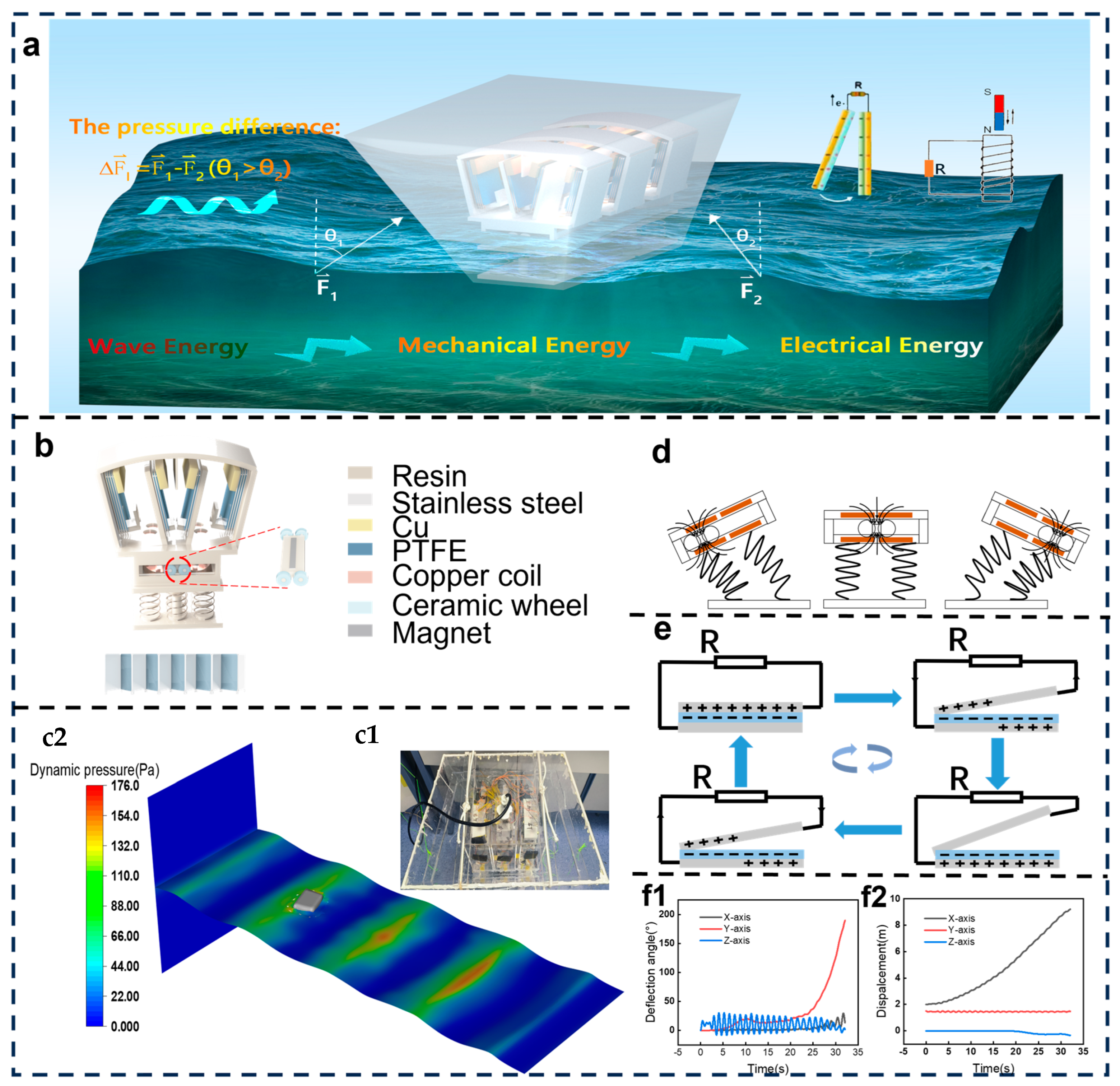
3.1. Structural Design and Working Mechanism

In general, a floating wave energy harvester consists of two primary functional components: a buoyant shell structure and an internal hybrid generator system. As shown in Figure 1a, the energy conversion process relies on the synergistic interaction of hydrodynamic forces acting on the shell, gravitational influences, and the inertial dynamics of the internal components. These coupled interactions induce the shell to follow wave-induced motion, converting wave mechanical energy into oscillations of the shell. This mechanical energy is subsequently transformed into electrical energy through two mechanisms: (1) periodic contact-separation of the triboelectric layers within the triboelectric nanogenerator (TENG) units and (2) magnetic flux variations in the electromagnetic generator (EMG) units, generating alternating currents in external circuits. In real ocean environments, the stochastic nature of sea waves and their dynamic interactions with both the shell and internal generators play a crucial role in determining energy harvesting efficiency. To overcome these challenges, a targeted design strategy was developed, integrating optimized structural configurations of hybrid TENG architectures with hydrodynamic shell engineering (the photographs of the fabricated hybrid generator are shown in Supplementary Material Figure S9).
As depicted in Figure 1b, the hybrid TENG structure primarily comprises a spring coupler and the hybrid generator body. The spring coupler consists of seven non-magnetic springs and 3D-printed supporting plates. It serves two key functions: first, it provides an elastic force to the hybrid nanogenerator body, enhancing the performance of the individual generators, lowering the operational threshold, and improving sensitivity. Second, it optimizes the coupling effect with the shell, thereby increasing the device’s output frequency under low-frequency excitation. The main framework of the hybrid generator is fabricated using 3D printing and incorporates two sets of stacked TENGs, along with a rolling-type EMG. The stacked TENGs are positioned on the left and right sides of the device, while the rolling-type EMG is located at the bottom, with its working coil embedded within the device body to enhance spatial utilization. Each stacked TENG set comprises ten and five vertical contact-separation units, along with counterweight brass blocks. The working principle of the EMG is illustrated in Figure 1d. During shell oscillation, the magnet moves with the cart, while the coil remains stationary. Based on the principle of electromagnetic induction, the reciprocating motion results in variations in the magnetic flux of the coil, inducing an alternating current. The spring coupler amplifies the cart’s oscillation frequency, thereby increasing the rate of magnetic flux variation while counteracting the resistance caused by the induced current. Figure 1e illustrates the working mechanism of the TENG. Utilizing electrostatic induction and triboelectric effects, charge transfer occurs when the two friction layers come into contact. The PTFE film acquires a negative charge, while the spring steel sheet becomes positively charged. As the shell moves, the brass block drives the PTFE film to separate from the spring steel sheet’s surface, generating a potential difference that directs free electrons through an external circuit, producing an electric current. Upon reverse thrust, the PTFE film recontacts the spring steel sheet, generating an opposite potential difference, which results in a reverse current, forming a periodic current output.
The shell, constructed from 5 mm thick acrylic plates, features an asymmetric trapezoidal geometry, as depicted in Figure 1(c1). The inclination angles of the front and rear wave-facing surfaces are 25° and 10°, respectively, while the left and right side surfaces each have an inclination angle of 10°. Additionally, a cubic shell with the same volume was fabricated as a control, as shown in Supplementary Material Figure S1. To compare the capability of different shell designs in harvesting wave mechanical energy, finite element simulations were conducted to analyze the motion of both shells under ocean waves with a wave height of 15 cm and a frequency of 0.8 Hz, as illustrated in Figure 1(c2) and Supplementary Material Figure S1. The maximum displacement of the cubic shell’s center of mass along the motion direction was determined to be 9 cm, with a maximum oscillation angle of 15.5°, as shown in Supplementary Material Figure S1. In contrast, the ATS exhibited a maximum displacement of 8.6 cm and a significantly larger maximum oscillation angle of 38°, as shown in Figure 1(f1,f2). Although the displacement of both shells was comparable, the notably greater oscillation angle of the ATS indicates its ability to induce enhanced relative motion, thereby improving the output performance of the internal hybrid TENG.
To systematically evaluate excitation levels and device output performance under different experimental conditions, an inertial measurement unit (IMU) from BEWISSENSING (BW-IMU500C) was incorporated into the shell. This IMU facilitated real-time data acquisition of acceleration along the x, y, and z axes, enabling a comprehensive analysis of device performance and its correlation with various excitation conditions across different shell hybrid TENG configurations.

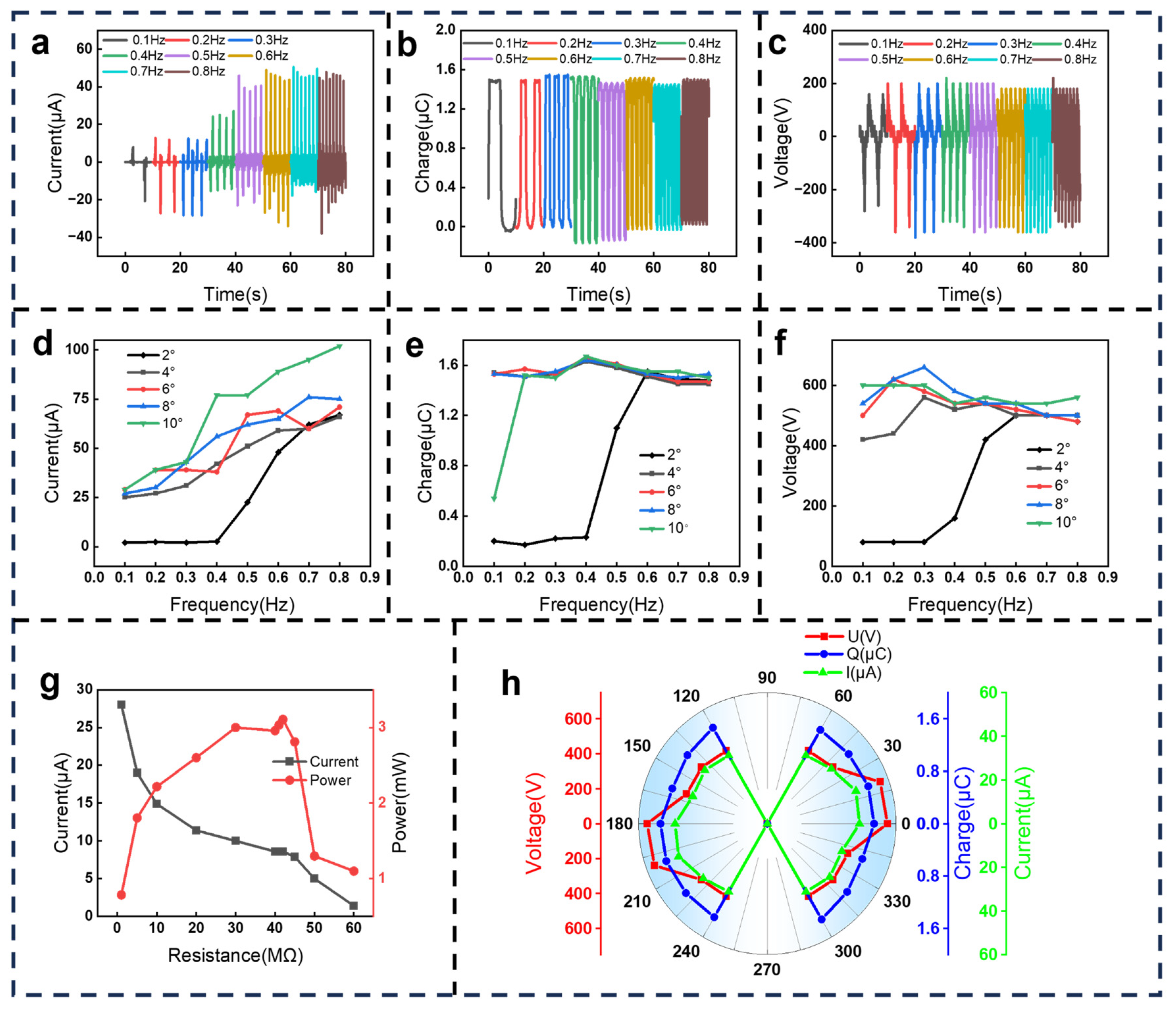
3.2. The Structural Optimization

To improve the adaptability of the hybrid triboelectric nanogenerator (TENG) to oceanic wave motions and extend its energy harvesting capability across a range of wave frequencies, this study systematically examined the effect of spring coupler parameters on the performance of the hybrid TENG. Through optimization of the spring coupler design, enhanced output characteristics were achieved by improving the coupling between the spring mechanism and the hybrid generator. The influence of the presence or absence of a spring coupler on the output performance and sensitivity of the hybrid TENG was initially analyzed. In the absence of the spring coupler, a single TENG layer required a minimum angular displacement of 14° at a frequency of 0.1 Hz to facilitate effective contact separation. At this displacement, the open-circuit voltage, short-circuit current, and transferred charge of a single TENG unit were recorded as 180 V, 16 µA, and 1.1 µC, respectively. For the EMG, the minimum operating angle was determined to be 2°, with an open-circuit voltage of 3.5 V and a short-circuit current of 0.7 mA. Detailed output variations with frequency and angle are provided in Supplementary Material Figure S2. In contrast, with the integration of the spring coupler, the performance of the hybrid TENG was significantly enhanced. At 0.1 Hz, a single TENG layer required only a 4° angular displacement for effective contact separation, resulting in an open-circuit voltage, short-circuit current, and transferred charge of 420 V, 17 µA, and 1.3 µC, respectively. The EMG output also exhibited substantial improvement, with an open-circuit voltage of 8 V and a short-circuit current of 2.3 mA. Additional details regarding output variations with frequency and angle are available in Supplementary Material Figure S2. These findings indicate that the incorporation of the spring coupler considerably reduces the operational threshold of the hybrid TENG and improves sensitivity, enabling more effective adaptation to low-frequency oceanic conditions. Without the spring coupler, the hybrid TENG output increases with frequency and angle; however, beyond a certain frequency threshold, sensitivity limitations restrict further output enhancement. Excessively high frequencies may lead to insufficient contact, thereby reducing charge transfer efficiency.
To examine the coupling degree between varying spring heights and the hybrid generator body, as well as their response to wide-frequency excitation, performance comparison tests of a single TENG unit were conducted on a six-degree-of-freedom platform. Each TENG unit was equipped with a brass block to ensure adequate contact. During the experiment, the platform’s swing angle was maintained at 6°, with the spring height ranging from 3.5 cm to 5 cm, and the test frequency varying from 0.1 Hz to 0.8 Hz. As illustrated in the three-dimensional color plot in Figure 2, each 3D plot is accompanied by two 2D plots on the right side, which specifically depict the output performance of the device under different test parameters. With an increase in spring height, the output frequency range of the transferred charge, open-circuit voltage, and short-circuit current progressively narrows. Higher spring heights lead to a reduced response to low-frequency excitation.
With an increase in spring height, the spring coupling undergoes greater deformation due to the gravitational force exerted by the hybrid generator body, requiring more energy for recovery. As a result, low-frequency excitation fails to effectively meet the energy demands of the spring. Notably, the frequency response range of the device is maximized when the spring height is set to 3.5 cm. Within the 0.1 Hz to 0.8 Hz frequency range, the device exhibits a balanced output performance, which increases with frequency and slightly declines after reaching saturation. This decline occurs because excessively high frequencies reduce the contact efficiency between the two friction layers of a single TENG, leading to a slight decrease in overall output. At a spring height of 3.5 cm, the peak output performance is achieved at a frequency of 0.6 Hz, with an open-circuit voltage of 580 V, a short-circuit current of 69 µA, and a transferred charge of 1.6 µC. Additionally, the energy output trend of the EMG follows a similar pattern to that of the single TENG. However, the EMG maintains stable output performance across the entire frequency range for spring heights between 3.5 cm and 5 cm due to its higher sensitivity, as it only requires movement of the device’s center of gravity rather than spring recovery. The magnet-carrying cart oscillates along the track, generating a maximum open-circuit voltage of 25.0 V and a maximum short-circuit current of 7.8 mA, with detailed performance data provided in Supplementary Material Figure S3. In conclusion, a comparison of performance with and without the spring coupler demonstrated that the spring coupler effectively reduces the operational threshold of the hybrid generator. To ensure optimal electrical output performance across the entire frequency range, a spring height of 3.5 cm was selected for all device units in subsequent experiments.

3.3. Performance on 6-DoF Platform Simulating Seesaw Motions

Considering the complexity and variability of real ocean environments, the output performance of individual TENG and EMG units was further analyzed under varying input conditions, including oscillation frequency, tilt angle, impedance matching, and motion direction. All experiments were conducted using a six-degree-of-freedom platform. As shown in Figure 3a–c, when the swing angle was maintained at 6°, the short-circuit current, transferred charge, and open-circuit voltage of a single TENG unit exhibited an increasing trend with frequency, reaching a saturation point before experiencing a slight decline. At a low frequency of 0.1 Hz, the short-circuit current, transferred charge, and open-circuit voltage of the single TENG were recorded as 29 µA, 1.53 µC, and 500 V, respectively. These results indicate that the TENG unit possesses a low startup frequency adaptability, making it well-suited for low-frequency excitations prevalent in real marine environments.
Meanwhile, the short-circuit current and open-circuit voltage of the EMG unit increased with frequency, reaching 3.7 mA and 11.6 V, respectively. Additionally, as illustrated in Figure 3d–f, an increase in the swing angle resulted in a gradual decrease in the startup frequency of the single TENG. When the swing angle reached or exceeded 4°, the single TENG achieved charge saturation output of 1.54 µC under the 0.1 Hz condition. Notably, at a swing amplitude of 2°, a sharp increase was observed in the transferred charge, short-circuit current, and open-circuit voltage within the 0.4 Hz to 0.6 Hz range. Specifically, the transferred charge increased from 0.23 μC to 1.1 μC, the short-circuit current rose from 2.6 μA to 22.5 μA, and the open-circuit voltage increased from 160 V to 500 V. This phenomenon was primarily attributed to resonance between the device and the external excitation, with the resonance frequency occurring around 0.5 Hz. Furthermore, under the conditions of 0.4 Hz and a swing angle of 6°, the output power of the single TENG was analyzed across different external load resistances. As shown in Figure 3h, the maximum peak power of the single TENG was recorded at 3.1 mW when the external resistance was set to 60 MΩ.
To assess the output stability of the hybrid electromagnetic–triboelectric generator, systematic performance tests were conducted under rotational angles ranging from 0° to 360° in 20° increments using a six-degree-of-freedom (6-DoF) platform. As illustrated in Figure 3h the single TENG unit exhibited directional dependence in energy harvesting, with effective operational angular ranges of 120–240° and −300–60°. In contrast, the EMG unit displayed near-circular output profiles, confirming its capability for omnidirectional energy harvesting. The output performance of the EMG unit, presented in Supplementary Material Figure S3, further supports this observation, as the nearly circular output pattern indicates strong omnidirectional output capability. These test results suggest that while the TENG unit exhibits directional limitations in regards to energy collection, the overall device maintains efficient wave energy harvesting under full rotational motion. Consequently, the hybrid electromagnetic generator is well-suited for multi-directional wave energy collection in real marine environments.

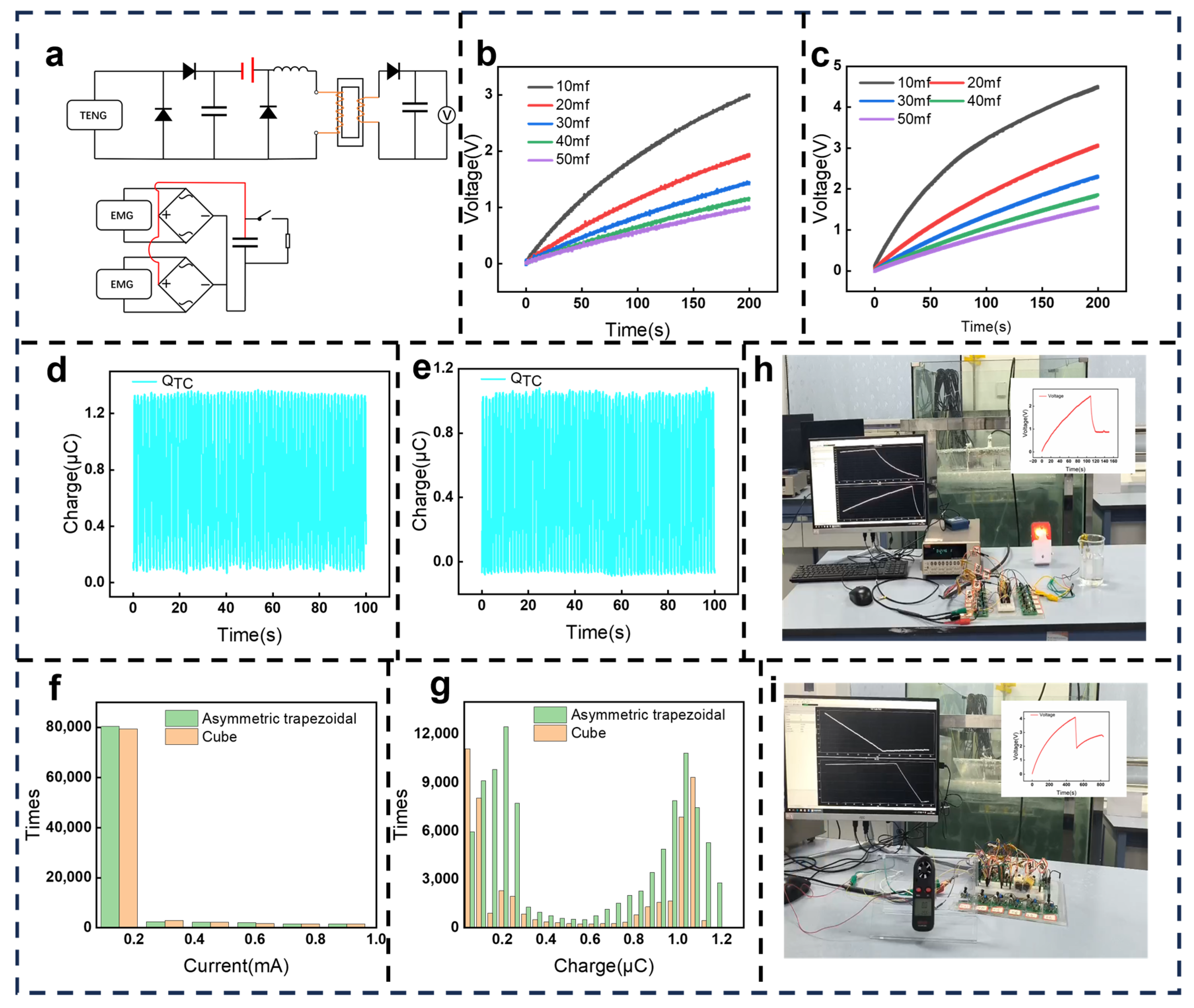
3.4. Power Management and Performance Comparison in Simulated Water Waves

To assess the energy absorption efficiency and output performance of shell–device coupled systems, three hybrid generator units were encapsulated within each of two geometrically distinct acrylic shells: a cubic shell and an ATS of equal volume. In conventional laboratory testing, load output power is commonly used to evaluate device performance, typically calculated using the equations P = I2R or P = U2/R to determine the maximum instantaneous load power. However, under real ocean wave conditions, both the frequency and amplitude of the device’s motion continuously vary, resulting in an absence of fixed output or optimal load power, rendering traditional load output evaluation methods inapplicable. Therefore, power generation performance was assessed by measuring the energy utilized to charge a capacitor within a fixed time period. Due to the high-voltage and low-current characteristics of the TENG output, direct rectification results in relatively low energy utilization, necessitating a power management circuit (spark-gap switch circuit) to step down the voltage and enhance the current for efficient energy extraction. In contrast, the low-voltage, high-current output of the EMG allows for direct rectification [41,42]. Both generators were connected in parallel to charge capacitors, as depicted in Figure 4a. The charging capability of the two sets of devices was tested using a six-degree-of-freedom platform, with detailed results provided in Supplementary Materials Figure S4. Under test conditions employing a 6° tilt and a frequency of 0.4 Hz, the devices encapsulated within the cubic shell charged 10 mF, 20 mF, 30 mF, 40 mF, and 50 mF capacitors to voltages of 3.81 V, 2.50 V, 1.86 V, 1.49 V, and 1.22 V, respectively, within 200 s. Under the same conditions, the other set of devices charged the capacitors to 3.43 V, 2.35 V, 1.85 V, 1.53 V, and 1.29 V, respectively. The results indicate that the charging energy of both sets of devices is comparable, primarily because the devices were fixed on the six-degree-of-freedom platform, where the external excitation directly acted on the internal device units, minimizing the influence of external shell geometry. Subsequently, a series of tests was conducted using simulated water waves generated in a wave tank. The simulated waves displayed a frequency of about 0.7 Hz and a wave height of about 2.3 cm. As shown in Figure 4b,c, charging tests were performed on 10 mF, 20 mF, 30 mF, 40 mF, and 50 mF capacitors under these simulated wave conditions. Within 200 s, the devices enclosed in the cubic shell charged the capacitors to 3.00 V, 1.94 V, 1.44 V, 1.15 V, and 1.01 V, respectively, while the devices within the ATS charged them to 4.51 V, 3.07 V, 2.32 V, 1.86 V, and 1.56 V, respectively. These values were 1.5, 1.58, 1.61, 1.62, and 1.54 times those recorded for the cubic shell, demonstrating the enhanced wave energy harvesting efficiency and coupling stability of the ATS. Further analysis of the output performance and response frequencies of the internal device units under identical wave conditions is presented in Figure 4d,e. The transferred charge of a single TENG in the ATS was measured at 1.29 μC, compared to 1.10 μC for the TENG in the cubic shell, representing an increase by a factor of 1.17. Additionally, the short-circuit current and open-circuit voltage of the TENG in the ATS were recorded at 72.46 μA and 274.49 V, respectively, which were 1.08 and 1.11 times greater than those of the cubic shell, as detailed in Supplementary Material Figure S5. The output performance of the EMG units was also evaluated under identical wave conditions. After rectification, the maximum current of the EMG unit in the ATS reached 4.45 mA, whereas in the cubic shell, it was 3.12 mA, with the former being 1.42 times the latter (detailed data are provided in Supplementary Material Figure S5). The experimental results indicate that under the consistent external excitation of the laboratory wave tank, the output waveforms of the device units remained highly stable. Additionally, the ATS exhibited superior wave absorption efficiency compared to that of the cubic shell. Enhancing the coupling between the shell and the internal device units proves to be an effective strategy for improving the overall output performance of the device.

3.5. Acceleration Analysis and Integration of the Device in Simulated Water Waves

To further analyze the differences in wave responsiveness between the two shells, inertial measurement units (IMUs) were used to record acceleration data along the x, y, and z axes for both shells, with the results provided in Supplementary Material Figure S6. The acceleration data exhibited periodic fluctuations in both cases. Along the z-axis, the ATS recorded a peak acceleration of 2.6 m·s−2 and a trough value of 2.3 m·s−2, whereas the cubic shell exhibited a peak of 1.4 m·s−2 and a trough of 1.8 m·s−2, indicating significantly lower peak acceleration compared to that of the ATS. A similar pattern was observed along the x- and y-axes. The small difference between peak and trough values suggests relatively stable wave conditions within the wave tank. Further frequency spectrum analysis of the acceleration data along all three axes, followed by normalization and smoothing, identified the most probable frequency for both shells as 0.7 Hz, which corresponded precisely with the wave frequency of the wave tank. The complete acceleration data for both shells along the x, y, and z axes are provided in Supplementary Material Figure S6.
At this most probable frequency, the acceleration values of the ATS along the x, y, and z axes were recorded as 1.9 m·s−2, 0.5 m·s−2, and 1.4 m·s−2, respectively, which were about 1.2 times, 5.5 times, and 2.3 times those of the cubic shell. Additionally, a statistical analysis was conducted on the output performance of the transferred charge from a single TENG unit and the EMG current over a 180 s period, as shown in Figure 4f,g. For the EMG current output within the 0–0.2 mA range, the ATS recorded 80,283 occurrences, whereas the cubic shell exhibited 79,199 occurrences. Regarding the transferred charge output of a single TENG unit, the ATS recorded 34,232 instances where the transferred charge exceeded 1 μC, while the cubic shell recorded only 16,647 occurrences, making the ATS about 2.06 times more effective. The experimental results indicate that under identical wave tank excitation, the ATS exhibited significantly higher responsiveness to water waves than did the cubic shell. These findings demonstrate that optimizing shell geometry can significantly enhance the output frequency of high-sensitivity device units, thereby improving overall energy harvesting performance.
The primary goal of wave energy triboelectric nanogenerators (TENGs) is to efficiently capture wave energy and supply power to electrical devices, including IoT terminals. In this study, the energy harvesting capability of an ATS-HG was evaluated under laboratory conditions. During the experiments, the TENG unit was integrated with a spark-switch circuit, while the electromagnetic generator (EMG) unit utilized a rectifier bridge, with both generators connected in parallel. Under simulated water waves with a frequency of 0.7 Hz and a wave height of 2.3 cm, the hybrid generator successfully charged a 10 mF capacitor to 2.4 V within 107 s, enabling the operation of a water level alarm (Figure 4h, with video provided in Supplementary Material Video S1). Further testing demonstrated that the hybrid generator charged the same capacitor to 4.1 V in 500 s, allowing the operation of an anemometer for wind speed measurement (Figure 4i, with video available in Supplementary Material Video S2). These results confirm the capability of the ATS-HG to efficiently harvest wave energy for powering various electronic devices, establishing a strong foundation for future testing in real-world marine environments and potential field deployments.

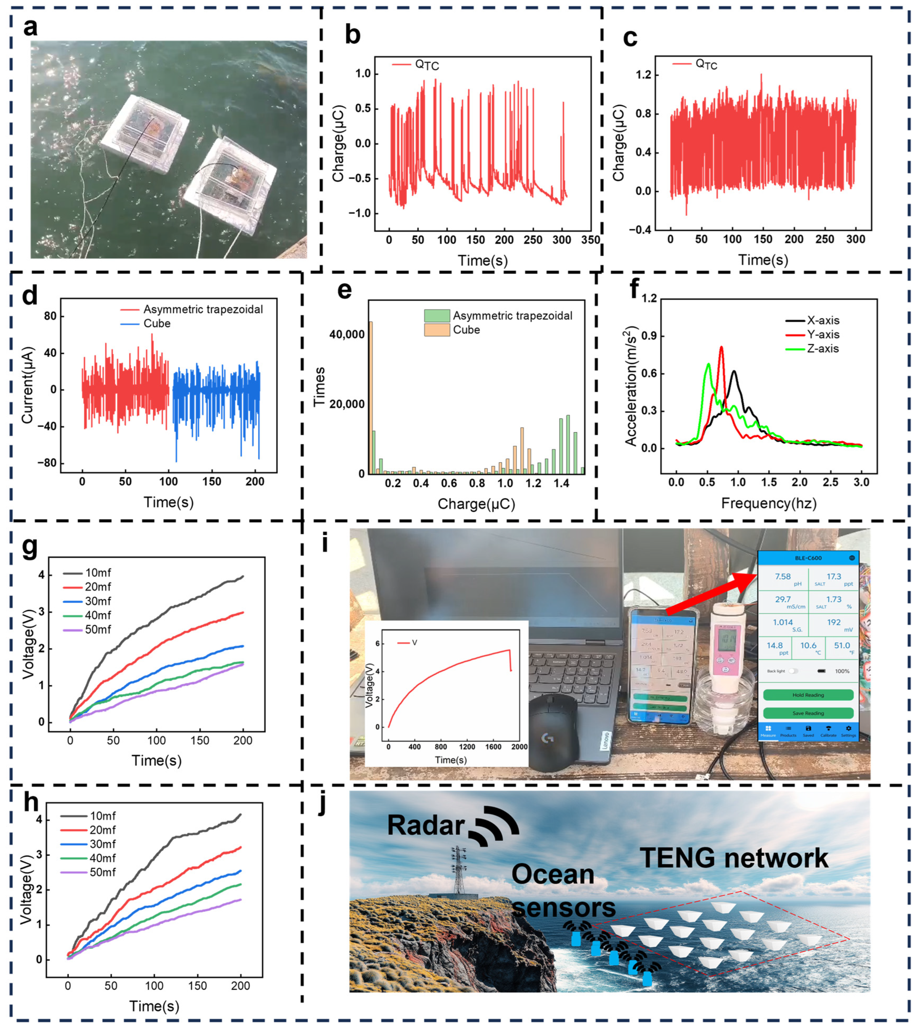
3.6. Performance Comparison, Statistical Analysis, and Integration of the Device in the Real Ocean

To verify the wave absorption capability and responsiveness of the ATS under stochastic wave excitation, field trials were conducted in the coastal waters of Fangchenggang, Guangxi, China. Real-time acceleration data were recorded using an inertial measurement unit (IMU) embedded within the encapsulated shell to analyze excitation levels, as shown in Figure 5a. In the ocean, wave properties were measured using a wave height gauge, with significant wave frequency (fs) and significant wave height (hs)—defined as the average height of the highest third of the waves and the average frequency—used as parameters to assess wave motion [43]. Detailed wave property data are provided in Supplementary Material Figure S7. Under conditions of fs = 0.485 Hz and Hs = 11.75 cm, as shown in Figure 5d, the short-circuit current of a single TENG unit encapsulated within the ATS reached 103 μA, representing a 24.1% increase compared to the 83 μA short-circuit current observed in the cubic shell. Additionally, the open-circuit voltage and transferred charge of the ATS-based TENG unit were recorded at 363 V and 1.54 μC, respectively, which were 113.5% and 21.3% higher than those measured for the cubic shell (170 V and 1.27 μC, respectively).
The detailed output waveforms are provided in Supplementary Material Figure S8. Unlike the uniform and stable waves generated by the laboratory water pump, natural ocean waves consist of multiple irregular waveforms superimposed on one another, leading to unpredictable variations. Consequently, the electrical output waveforms of the hybrid generator under ocean wave excitation also exhibit irregular characteristics. The ATS demonstrated superior wave absorption capability under random wave excitation, achieving higher output performance compared to that of the cubic shell under constant excitation in the laboratory water tank. Further evaluation of the two shells’ responses to random oceanic waves was conducted by measuring the transferred charge of a single TENG unit over a 300 s period. As shown in Figure 5b,c, the TENG unit encapsulated in the ATS generated 276 electrical pulse signals, with a response frequency of 0.92 Hz, whereas the TENG unit within the cubic shell produced 84 pulse signals, with a response frequency of 0.28 Hz. The response frequency of the ATS-based TENG unit was about 3.29 times higher than that of the cubic shell, indicating enhanced wave energy harvesting efficiency under stochastic wave conditions. Additionally, statistical analysis of the transfer charge output over a 100 s period is presented in Figure 5e. In the ATS, the frequency of transfer charge outputs exceeding 1 μC for the TENG unit was recorded at 71,341, whereas the corresponding frequency for the TENG unit in the cubic shell was 36,918, making the output of the former about 1.93 times higher than that of the latter. These experimental results confirm that under real oceanic random wave excitation, the ATS exhibits significantly superior wave absorption capacity and responsiveness compared to that of the cubic shell. The coupling between the ATS and the device unit enhances overall output performance, while also highlighting the limitations of laboratory-simulated ocean wave conditions. These findings emphasize the necessity for more accurate simulations that better capture the complexities of natural ocean waves in future research.
To assess the frequency amplification capability of the ATS under random wave excitation and its applicability under real ocean conditions, variations in acceleration along the x, y, and z axes inside the shell were analyzed, along with the output performance of the hybrid generator. As shown in Figure 5f, spectral analysis of the acceleration data along all three axes was conducted, followed by normalization and smoothing. The results indicated that the most probable frequencies of the ATS along the x, y, and z axes were 0.94 Hz, 0.73 Hz, and 0.52 Hz, respectively, which were 0.94 times, 0.55 times, and 0.11 times higher than the actual fs of ocean wave. These findings suggest that the ATS exhibits a strong frequency amplification effect, converting low-frequency ocean waves into higher-frequency oscillations, thereby improving coupling with the internal device and enhancing output performance. Subsequently, charging tests were conducted under ocean wave conditions of fs = 0.485 Hz and Hs = 11.75 cm using devices encapsulated in both types of shells with 10 mF, 20 mF, 30 mF, 40 mF, and 50 mF capacitors, as shown in Figure 5g,h.
The device encapsulated in the cubic shell charged the capacitors to 3.97 V, 2.99 V, 2.08 V, 1.64 V, and 1.58 V within 200 s, while the device encapsulated in the ATS achieved voltages of 4.15 V, 3.22 V, 2.54 V, 2.15 V, and 1.72 V, which were 1.05, 1.08, 1.22, 1.31, and 1.09 times higher, respectively. These results not only demonstrate the superior charging capability of the ATS but also confirm its efficient energy collection and stable coupling with the internal device unit under random wave conditions. Building upon these findings, additional application tests were conducted under identical sea conditions, leading to the successful development of a self-powered wireless water quality monitoring system. This system comprises devices encapsulated in the ATS, a data acquisition and signal transmission unit, and a receiving end. As shown in Figure 5i, after charging a 50 mF capacitor for 30 min, the voltage reached 5.54 V. The water quality detection pen was activated, and the capacitor successfully powered the device, enabling data collection and transmission to the receiving unit (video provided in Supplementary Material Video S3). In conclusion, devices encapsulated in the ATS demonstrate significant application potential in real ocean environments. As illustrated in Figure 5j, hybrid generator arrays based on these devices could be deployed near islands or across vast ocean surfaces to harness low-frequency ocean wave energy, providing power for small intelligent devices, environmental sensors, and offshore wireless communication equipment. Due to its high sensitivity to low-frequency waves, the ATS-HG is ideally suited for continuously powering distributed, low-power ocean monitoring systems, thereby reducing reliance on battery replacement or wired power sources. As a result, it holds broad application potential in oceanic Internet of things (IoT) deployments, maritime defense, underwater monitoring, and various other marine-related fields.

4. Conclusions

In summary, a hybrid nanogenerator incorporating an innovative ATS structure and integrated triboelectric–electromagnetic modules was designed and fabricated, achieving broadband frequency adaptability and omnidirectional wave energy harvesting capabilities. Finite element physical simulations were conducted to analyze the hydrodynamic performance of the ATS, demonstrating its superiority over conventional cubic geometries under controlled wave conditions. Systematic comparisons of generator outputs were performed across laboratory simulations, including six-degree-of-freedom (6-DoF) platform tests and wave tank experiments, as well as real ocean environments. Using inertial measurement units (IMUs) embedded within the shell, acceleration characteristics were systematically analyzed under both simulated laboratory water waves and real ocean wave conditions. Particular attention was given to the statistical properties of acceleration under stochastic ocean waves and the correlation between shell design and device output performance. Due to the ATS’s enhanced wave collection efficiency and high responsiveness, the transferred charge of a single TENG unit encapsulated within this shell reached 1.54 μC, with a short-circuit current of 103 μA and an open-circuit voltage of 363 V, which were 1.21, 1.24, and 2.13 times higher, respectively, compared to those of the cubic shell.
Additionally, the peak charge output frequency within 300 s reached 276 pulses, which was 3.29 times higher than that of the cubic shell. The most probable acceleration frequencies along the x, y, and z axes of the ATS were 0.94 Hz, 0.73 Hz, and 0.52 Hz, respectively, corresponding to 1.94, 1.55, and 1.11 times the random wave frequencies observed in the real ocean. Under real ocean conditions, the integrated device encapsulated in the ATS successfully charged a 50 mF capacitor to 5.54 V within 30 min, enabling the operation of a Bluetooth-equipped water quality sensor and facilitating data transmission to a mobile terminal. These results highlight its potential for self-powered ocean sensing applications. This study introduces a novel approach to shell design through wave simulation and coordinated integration with energy-harvesting devices, enabling efficient wave energy conversion. The findings provide a foundation for the future optimization of high-performance wave energy harvesting systems. By first designing the shell through wave simulation based on the principle of wave–body coupling and then integrating it with the energy harvesting device, this study offers a novel approach for enhancing the performance of wave energy converters. It provides new insights into the future optimization of high-performance wave energy harvesting systems and lays a solid groundwork for large-scale, array-based applications.

Supplementary Materials

The following supporting information can be downloaded at: https://www.mdpi.com/article/10.3390/en18061502/s1, Figure S1: Photograph and simulation image of the cubic shell; Figure S2: The output performance of a single EMG and TENG with or without springs on a six-degree-of-freedom platform at different angles and frequencies; Figure S3: he output performance of a single EMG on a six-degree-of-freedom platform under varying frequencies and spring heights; Figure S4: The performance of two integrated devices with different housings on a six-degree-of-freedom platform at a frequency of 0.4 Hz and an angle of 6°; Figure S5: The performance of two integrated devices with different shells in a laboratory tank environment at a frequency of 0.7 Hz and a wave height of 2.3 cm; Figure S6: The acceleration variations of two shell-integrated devices in a laboratory tank environment at a frequency of 0.7 Hz and a wave height of 2.3 cm; Figure S7: The characteristics of real ocean waves are as follows: (a) Wave height data measured by the wave gauge over 100 seconds; Figure S8: The output performance of a single TENG in two types of shells under real ocean conditions with a significant frequency of 0.485 Hz and a significant wave height of 11.75 cm; Figure S9: Photographs of the fabricated hybrid generator; Note S1: Calculation methods of significant wave height and significant wave frequency; Video S1: The ATS-HG power for a water level alarm in the water tank; Video S2: The ATS-HG power for an anemometer for wind speed measurements in the water tank; Video S3: The ATS-HG power for a Bluetooth-equipped water quality sensor system to work in real ocean.

Author Contributions

Conceptualization, H.L. and D.G.; methodology, H.L. and H.W.; software, H.L., J.L. and H.Z.; validation, H.L., H.W. and L.W.; formal analysis, H.L. and L.W.; investigation, H.L.; data curation, H.L.; writing—original draft preparation, H.L. and L.W.; writing—review and editing, H.L. and L.W.; visualization, H.L. and L.W.; supervision, L.W.; project administration, L.W. All authors have read and agreed to the published version of the manuscript.

Funding

The research was supported by the National Key R & D Project from the Ministry of Science and Technology (2021YFA1201603) and the Natural Science Foundation of Guangxi Province (Grant No. 2021GXNSFAA075009).

Data Availability Statement

Data are contained within the article.

Acknowledgments

The research was supported by all authors.

Conflicts of Interest

The authors declare no conflicts of interest.

References

  1. Zheng, C.; Shao, L.; Shi, W.; Su, Q.; Lin, G.; Li, X.; Chen, X. An assessment of global ocean wave energy resources over the last 45 a. Acta Oceanol. Sin. 2014, 33, 92–101. [Google Scholar] [CrossRef]
  2. Liu, T.; Yu, J.; Yu, Y.; Zhang, X.; Zhou, B.; Yin, L. Characterization of Wave Power Resources off the Coast of Guangdong. Processes 2023, 11, 2221. [Google Scholar] [CrossRef]
  3. Borthwick, A.G.L. Marine Renewable Energy Seascape. Engineering 2016, 2, 69–78. [Google Scholar] [CrossRef]
  4. Mwasilu, F.; Jung, J.-W. Potential for power generation from ocean wave renewable energy source: A comprehensive review on state-of-the-art technology and future prospects. IET Renew. Power Gener. 2019, 13, 363–375. [Google Scholar] [CrossRef]
  5. Kumara, K.D.R.J. On the placement of a wave manipulator suitable for energy harnessing in the Nearshore. Cogent Eng. 2022, 9, 2124636. [Google Scholar] [CrossRef]
  6. Jiang, X.; Gao, D.; Hua, F.; Yang, Y.; Wang, Z. An Improved Approach to Wave Energy Resource Characterization for Sea States with Multiple Wave Systems. J. Mar. Sci. Eng. 2022, 10, 1362. [Google Scholar] [CrossRef]
  7. Chen, W.; Meng, X.; Li, Y.; Gao, F. Type synthesis of parallel mechanisms capturing wave energy. Proc. Inst. Mech. Eng. Part C-J. Mech. Eng. Sci. 2019, 233, 6689–6697. [Google Scholar] [CrossRef]
  8. Yan, J.; Mei, N.; Zhang, D.; Zhong, Y.; Wang, C. Review of wave power system development and research on triboelectric nano power systems. Front. Energy Res. 2022, 10, 966567. [Google Scholar] [CrossRef]
  9. Salman, M.; Sorokin, V.; Aw, K. Systematic literature review of wave energy harvesting using triboelectric nanogenerator. Renew. Sustain. Energy Rev. 2024, 201, 114626. [Google Scholar] [CrossRef]
  10. Hang, X.; Jiang, T.; Liu, G.; Xiao, T.; Xu, L.; Li, W.; Xi, F.; Zhang, C.; Wang, Z.L. Triboelectric Nanogenerator Networks Integrated with Power Management Module for Water Wave Energy Harvesting. Adv. Funct. Mater. 2019, 29, 1807241. [Google Scholar]
  11. Wang, Z.L.; Jiang, T.; Xu, L. Toward the blue energy dream by triboelectric nanogenerator networks. Nano Energy 2017, 39, 9–23. [Google Scholar] [CrossRef]
  12. Wang, Z.L. Triboelectric nanogenerators as new energy technology and self-powered sensors—Principles, problems and perspectives. Faraday Discuss. 2014, 176, 447–458. [Google Scholar] [CrossRef]
  13. Zheng, Y.; Ni, Y.; Zi, Y.; Cui, H.; Li, X. Enhanced triboelectric nanogenerators in saline environments and their applications in the ocean. Nano Energy 2024, 126, 109636. [Google Scholar] [CrossRef]
  14. Zhao, X.J.; Wang, H.L.; Wang, Z.L.; Wang, J. Nanocomposite Electret Layer Improved Long-Term Stable Solid-Liquid Contact Triboelectric Nanogenerator for Water Wave Energy Harvesting. Small 2024, 20, 2310023. [Google Scholar] [CrossRef]
  15. Wu, M.; Guo, W.; Dong, S.; Liu, A.; Cao, Y.; Xu, Z.; Lin, C.; Zhang, J. A hybrid triboelectric nanogenerator for enhancing corrosion prevention of metal in marine environment. npj Mater. Degrad. 2022, 6, 73. [Google Scholar] [CrossRef]
  16. Sun, X.; Shang, C.; Ma, H.; Li, C.; Xue, L.; Xu, Q.; Wei, Z.; Li, W.; Yalikun, Y.; Lai, Y.-C.; et al. A tube-shaped solid–liquid-interfaced triboelectric–electromagnetic hybrid nanogenerator for efficient ocean wave energy harvesting. Nano Energy 2022, 100, 107540. [Google Scholar] [CrossRef]
  17. Zhao, B.; Dong, S.; Li, Z.; Zhang, B. Multi-Physics Coupling Modeling Method for the Rolling-Spherical Triboelectric Nanogenerator. Tribology 2020, 40, 680–686. [Google Scholar]
  18. Liang, X.; Jiang, T.; Liu, G.; Feng, Y.; Zhang, C.; Wang, Z.L. Spherical triboelectric nanogenerator integrated with power management module for harvesting multidirectional water wave energy. Energy Environ. Sci. 2020, 13, 277–285. [Google Scholar] [CrossRef]
  19. Gao, W.; Shao, J.; Sagoe-Crentsil, K.; Duan, W. Investigation on energy efficiency of rolling triboelectric nanogenerator using cylinder-cylindrical shell dynamic model. Nano Energy 2021, 80, 105583. [Google Scholar] [CrossRef]
  20. Hong, H.; Chen, T.; Yang, J.; Hu, Y.; Hu, J.; Li, D.; Liu, F.; Liu, L.; Wu, H. Omnidirectional water wave energy harvesting by a spherical triboelectric nanogenerator with sliced-pizza-shaped electrodes. Cell Rep. Phys. Sci. 2024, 5, 101933. [Google Scholar] [CrossRef]
  21. Zhang, C.; Yuan, W.; Zhang, B.; Yang, J.; Hu, Y.; He, L.; Zhao, X.; Li, X.; Wang, Z.L.; Wang, J. A Rotating Triboelectric Nanogenerator Driven by Bidirectional Swing for Water Wave Energy Harvesting. Small 2023, 19, 2304412. [Google Scholar] [CrossRef] [PubMed]
  22. Liu, L.; Shi, Q.; Lee, C. A novel hybridized blue energy harvester aiming at all-weather IoT applications. Nano Energy 2020, 76, 105052. [Google Scholar] [CrossRef]
  23. Lin, Z.; Zhang, B.; Guo, H.; Wu, Z.; Zou, H.; Yang, J.; Wang, Z.L. Super-robust and frequency-multiplied triboelectric nanogenerator for efficient harvesting water and wind energy. Nano Energy 2019, 64, 103908. [Google Scholar] [CrossRef]
  24. Xu, Z.; Chen, L.; Zhang, Z.; Han, J.; Chen, P.; Hong, Z.; Jiang, T.; Wang, Z.L. Durable Roller-Based Swing-Structured Triboelectric Nanogenerator for Water Wave Energy Harvesting. Small 2023, 20, 2307288. [Google Scholar] [CrossRef]
  25. Zhang, S.; Jing, Z.; Wang, X.; Zhu, M.; Yu, X.; Zhu, J.; Cheng, T.; Zhao, H.; Wang, Z.L. Soft-bionic-fishtail structured triboelectric nanogenerator driven by flow-induced vibration for low-velocity water flow energy harvesting. Nano Res. 2023, 16, 466–472. [Google Scholar] [CrossRef]
  26. Jing, Z.; Zhang, J.; Wang, J.; Zhu, M.; Wang, X.; Cheng, T.; Zhu, J.; Wang, Z.L. 3D fully-enclosed triboelectric nanogenerator with bionic fish-like structure for harvesting hydrokinetic energy. Nano Res. 2022, 15, 5098–5104. [Google Scholar] [CrossRef]
  27. Cao, Y.; Tao, K.; Ren, C.; Chen, Z.; Wang, Y.; Yi, H. A sea snake structure wave power generator for efficiently harvesting ocean wave energy with flexible structure. In Proceedings of the 46th Annual Conference of the IEEE-Industrial-Electronics-Society (IECON), Singapore, 18–21 October 2020; pp. 3489–3492. [Google Scholar]
  28. Yar, A. High performance of multi-layered triboelectric nanogenerators for mechanical energy harvesting. Energy 2021, 222, 119949. [Google Scholar] [CrossRef]
  29. Yang, X.; Huo, D.; Su, J.; He, Z. Portable Multi-Layer Capsule-Shaped Triboelectric Generator for Human Motion Energy Harvesting. Micromachines 2024, 15, 852. [Google Scholar] [CrossRef] [PubMed]
  30. Li, Y.; Guo, Z.; Zhao, Z.; Gao, Y.; Yang, P.; Qiao, W.; Zhou, L.; Wang, J.; Wang, Z.L. Multi-layered triboelectric nanogenerator incorporated with self-charge excitation for efficient water wave energy harvesting. Appl. Energy 2023, 336, 120792. [Google Scholar] [CrossRef]
  31. Li, S.; Chen, C.; Guo, D.; Liu, H.; Ning, H.; Liu, G.; Wan, L. Highly Sensitive Hybrid Triboelectric Nanogenerator with Ferris-Wheel-Like Structure for Ocean Wave Energy Harvesting. Adv. Sustain. Syst. 2024, 8, 2400310. [Google Scholar] [CrossRef]
  32. Wen, H.; Liu, H.; Wang, X.; Liu, G.; Zhou, P.; Zhou, W.; Tuo, L.; Qu, H.; Zhai, L.; Wan, L.; et al. Enhanced hybrid generator with spring coupling effect for low-grade water wave energy harvesting. Nano Energy 2025, 133, 110488. [Google Scholar] [CrossRef]
  33. Lee, K.; Lee, J.-w.; Kim, K.; Yoo, D.; Kim, D.S.; Hwang, W.; Song, I.; Sim, J.-Y. A Spherical Hybrid Triboelectric Nanogenerator for Enhanced Water Wave Energy Harvesting. Micromachines 2018, 9, 598. [Google Scholar] [CrossRef]
  34. Saadatnia, Z.; Asadi, E.; Askari, H.; Zu, J.; Esmailzadeh, E. Modeling and performance analysis of duck-shaped triboelectric and electromagnetic generators for water wave energy harvesting. Int. J. Energy Res. 2017, 41, 2392–2404. [Google Scholar] [CrossRef]
  35. Ryu, H.; Yoon, H.J.; Kim, S.W. Hybrid Energy Harvesters: Toward Sustainable Energy Harvesting. Adv. Mater. 2019, 31, 1802898. [Google Scholar] [CrossRef]
  36. Wang, H.; Zhu, Q.; Ding, Z.; Li, Z.; Zheng, H.; Fu, J.; Diao, C.; Zhang, X.; Tian, J.; Zi, Y. A fully-packaged ship-shaped hybrid nanogenerator for blue energy harvesting toward seawater self-desalination and self-powered positioning. Nano Energy 2019, 57, 616–624. [Google Scholar] [CrossRef]
  37. Xu, S.; Liu, G.; Wang, J.; Wen, H.; Cao, S.; Yao, H.; Wan, L.; Wang, Z.L. Interaction between Water Wave and Geometrical Structures of Floating Triboelectric Nanogenerators. Adv. Energy Mater. 2022, 12, 2103408. [Google Scholar] [CrossRef]
  38. Zhai, L.; Wen, H.; Liu, H.; Guo, D.; Liu, G.; Qu, H.; Wan, L.; Yao, H.; Zhai, J. High-sensitivity blue-energy-shuttle and in-situ electrical behaviors in ocean. Nano Energy 2024, 125, 109546. [Google Scholar] [CrossRef]
  39. Guo, D.; Chen, C.; Li, J.; Zhai, L.; Li, S.; He, S.; Feng, J.; Wan, L.; Liu, G.; Zhai, J. Structural Quality Factor of Flo-TENG under Stochastic Wave Excitation. Adv. Sci. 2024, 11, 2405165. [Google Scholar] [CrossRef]
  40. Xu, S.; Zhang, J.; Su, E.; Li, C.; Tang, W.; Liu, G.; Cao, L.N.Y.; Wang, Z.L. Dynamic behavior and energy flow of floating triboelectric nanogenerators. Appl. Energy 2024, 367, 123468. [Google Scholar] [CrossRef]
  41. Wang, Z.; Liu, W.; He, W.; Guo, H.; Long, L.; Xi, Y.; Wang, X.; Liu, A.; Hu, C. Ultrahigh Electricity Generation from Low-Frequency Mechanical Energy by Efficient Energy Management. Joule 2021, 5, 441–455. [Google Scholar] [CrossRef]
  42. Harmon, W.; Bamgboje, D.; Guo, H.; Hu, T.; Wang, Z.L. Self-driven power management system for triboelectric nanogenerators. Nano Energy 2020, 71, 104642. [Google Scholar] [CrossRef]
  43. Holthuijsen, L.H. Waves in Oceanic and Coastal Waters; Cambridge University Press: Cambridge, UK, 2007; p. 70. ISBN 978-0-521-86028-4. [Google Scholar]
Figure 1. (a) Conceptual illustration of the ATS−HG for ocean energy harvesting (The arrows indicate the direction of electron movement.). (b) Schematic representation of the internal hybrid generator structure. (c1) Physical photograph of the ATS-HG. (c2) Motion simulation of the shell with identical parameters under finite element analysis. (d) Schematic of the EMG working principle. (e) Schematic of the TENG working principle. (f1) Variation in shell angle along the x, y, and z axes over time under finite element simulation. (f2) Variation in shell acceleration along the x, y, and z axes over time under finite element simulation.
Energies 18 01502 g001
Figure 2. Output performance of a single TENG on a six-degree-of-freedom platform under varying frequencies and spring heights. (a) Waterfall plot showing short-circuit current variation with frequency and spring height; (a1) short-circuit current as a function of frequency; (a2) short-circuit current as a function of spring height. (b) Waterfall plot depicting transferred charge variation with frequency and spring height; (b1) transferred charge as a function of frequency; (b2) transferred charge as a function of spring height. (c) Waterfall plot illustrating open-circuit voltage variation with frequency and spring height; (c1) open-circuit voltage as a function of frequency; (c2) open-circuit voltage as a function of spring height.
Energies 18 01502 g002
Figure 3. (ac) Output performance of a single TENG unit on the six-degree-of-freedom platform at varying frequencies: (a) short-circuit current; (b) transferred charge; (c) open-circuit voltage. (df) Output performance of a single TENG unit on the six-degree-of-freedom platform at different frequencies and angles: (d) short-circuit current; (e) transferred charge; (f) open-circuit voltage. (g) Peak power density distribution of a single TENG unit under 0.4 Hz and 6° conditions. (h) Schematic representation of the horizontal effective collection range output of a single TENG unit.
Energies 18 01502 g003
Figure 4. Performance of integrated devices with two types of shells under laboratory water tank conditions at a frequency of 0.7 Hz and a wave height of 2.3 cm. (a) Schematic representation of the energy management circuit for the integrated device. (b) Schematic illustration of the charging behavior of the integrated device with a cubic shell for different capacitances. (c) Schematic illustration of the charging behavior of the integrated device with an asymmetric trapezoidal enclosure for different capacitances. (d) Transferred charge of a single TENG under the ATS. (e) Transferred charge of a single TENG under the cubic enclosure. (f) Statistical analysis of EMG current output over 100 s. (g) Statistical analysis of TENG charge output over 100 s. (h,i) Operation of the water level alarm and anemometer powered by the ATS-HG: (h) water level alarm; (i) anemometer.
Energies 18 01502 g004
Figure 5. Under real ocean conditions, with a significant frequency of 0.485 Hz and a significant wave height of 11.75 cm: (a) physical image of the two types of shell-integrated devices; (b) charge output of a single TENG unit within the cubic shell over 300 s; (c) charge output of a single TENG unit within the ATS over 300 s. (d) Comparison of short-circuit current output from a single TENG unit under both shell types. (e) Statistical analysis of the charge output of a single TENG unit over 100 s for both shell types. (f) Acceleration distribution analysis of the ATS along the x, y, and z axes. (g,h) Charging performance of integrated devices within both shell types for different capacitor sizes in a marine test environment: (g) cubic shell; (h) ATS. (i) ATS-HG powering a self-sustained wireless water quality monitoring system in a real marine environment. (j) Schematic representation of the scenario for deploying a self-powered marine environmental wireless monitoring system.
Energies 18 01502 g005
Disclaimer/Publisher’s Note: The statements, opinions and data contained in all publications are solely those of the individual author(s) and contributor(s) and not of MDPI and/or the editor(s). MDPI and/or the editor(s) disclaim responsibility for any injury to people or property resulting from any ideas, methods, instructions or products referred to in the content.

