1. Introduction
Regarding the extraction of HVO and EHVO, methods are categorised into well based and non-well based. Well-based methods can be divided into primary, secondary, and tertiary techniques. Primary, or cold production techniques, are applicable when the oil has relatively low viscosity, allowing it to flow towards the wellbore due to the natural forces within the reservoir. The average oil recovery factors (ORF) at this stage for HVO and EHVO are 5–10%. Fields in the Orinoco Belt in Venezuela, the Brazilian shelf, and pilot projects in Russian fields such as the Usinskoye and Mishkinskoe are developed using primary techniques. Notably, the “Cold Heavy Oil Production with Sand” (CHOPS) is applied at the Lloydminster field in Canada, where a mixture of sand and oil is extracted in weakly cemented rocks through gas-driven screw pumps [
1]. Despite high annual production rates, developing HVO and EHVO in this way alters the reservoir properties and can lead to its damage. One of the primary methods for accessing and producing HVO and EHVO from low-permeability reservoirs could be the hydraulic fracturing [
2,
3].
Secondary recovery methods, like flooding, are also used for HVO and EHVO fields, as they are for traditional oil reservoirs. The average oil recovery factors at this stage range from 20 to 40%, but they significantly decrease as the viscosity of the oil increases. In the case of EHVO fields with no underlying water, the technology is almost ineffective. Experience with developing HVO and EHVO fields shows that the injection of large-volume polymer solution slugs, instead of traditional water flooding, is a viable secondary recovery method.
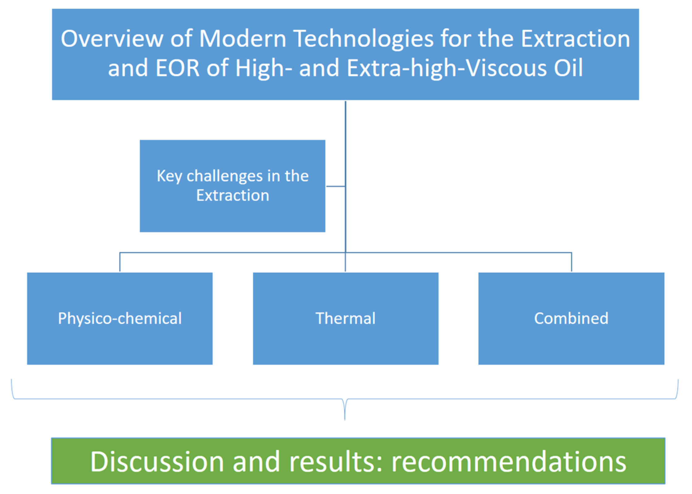
Tertiary recovery methods typically involve the introduction of additional energy into the reservoir, increasing the displacement or sweep efficiency. In the case of HVO and EHVO extraction, thermal, physico-chemical methods, and their combinations are most commonly used. The development of HVO and EHVO extraction technologies in Russia is associated with scientific work led by researchers such as Altunina, L. [
4], Antoniadi, D. [
5], Gazizov, A. [
6], Ibatullin, R. [
7], Ruzin, L. [
8,
9], Morozyuk, O. [
10], and others. In the international scientific community, studies by Farouq Ali, S. [
11], Butler, R. [
12], Bai, B. [
13], Shah, A. [
1], Hascakir, B. [
14], Edmunds, N., Lake, L., Seright, R. [
15,
16], Delamaide, E. [
17], Zhahg, H., Thomas, A. et al. [
18] have been recognised. The injection of thermal agents is used in certain fields as a primary or secondary method of extracting HVO and EHVO. This paper focuses particularly on these extraction methods. For easier navigation, the following flowchart is provided (
Figure 1).
2. Key Challenges in the Extraction of Heavy and Super-Heavy Oil
According to the current classification of oil reserves and resources in Russia, natural bitumens (NB) are not distinguished as a separate category of reserves, as is the case in the American Petroleum Institute (API) classification. There is a classification of oils based on density, where heavy oils have a density of 0.871–0.895 g/cm3, oils with a density greater than 0.895 g/cm3 are classified as bituminous, and there is also a classification of oils based on viscosity: 30.1–200 mPa·s—HVO, >200 mPa·s—EHVO. The viscosity of NB can typically reach >10,000 mPa·s, and in this regard, they are classified as EHVO according to the current Russian classification. Thus, the terms “heavy oil” and “super-heavy oil” in this article are based on the Russian classification and only partially correspond to the term “heavy oil” in the API.
The extraction mechanism for HVO and EHVO through the introduction of additional energy into the reservoir via steam flooding or in situ combustion is primarily aimed at reducing the viscosity of the extracted fluid. At the same time, the increase in the displacement efficiency occurs due to the improvement of the mobility ratio between the oil and the displacing fluid (water, polymer solution, etc.). The enhancement of the recovery factor for HVO and EHVO is also related to the synergy of these mechanisms, for example, through the injection of hot water or hot polymer into the reservoir or by expanding the coverage of the reservoir impact via fluid flow redirection with plugging systems (e.g., injection of small volumes of chemical solutions into already thief zones of the reservoir). More details on each of these technologies will be presented in the relevant section of this paper.
Globally, capital- and energy-intensive thermal methods dominate the number of EOR projects for HVO and EHVO extraction. A complicating factor for the extraction of HVO and EHVO, from the perspective of project profitability, is the production of associated water [
19]. Previous works did not sufficiently address the mechanisms of water production in fields with HVO and EHVO being developed by thermal methods. In general, the extracted water can be divided into two types. The first is water coming from active aquifers or injection wells, which aids in the displacement of oil towards the production wells, with minimal volume not exceeding the economic limit defined by the water–oil ratio (WOR). The second type is excessive, disproportionate water volumes entering the well. It is known that the WOR in conventional reservoirs is around 3, but in HVO and EHVO reservoirs, the WOR increases and is approximately 10 [
20].
Based on accumulated global experience in developing HVO and EHVO fields, water production mechanisms can be generalised relative to the depth of productive layers (
Figure 2 and
Figure 3). It should be noted that the depth of the productive layer is one of the determining factors when choosing the working agent: steam or water.
In general, there are both geological and technological causes for the water breakthrough in production wells. Geological factors are associated with the geological and physical characteristics of the reservoir, including the presence of bottom water, zones of vertical cracks, highly permeable channels and fractures, water lenses, and other features.
The technological factor relates to the operational regime of wells. In the Russian Federation, the development of carbonate formations of the Lower and Middle Carboniferous in the Usinskoe (Moscovian, Kasimovian, and Asselian stages), Gremihinskoe (Bashkirian stage), and Mishkinskoe (Tournai stage, Cherepetsky horizon) fields is predominantly carried out using thermal methods (hot water or steam flooding) combined with a reservoir pressure maintenance (RPM) system. The injection well stock primarily consists of vertical or deviated wells drilled into the reservoir with top depths of 800 m or more. The development experience of these fields demonstrates water breakthroughs from the RPM system (both cold and hot water) into overlying formations via vertical cracks. Reservoirs developed using steam injection show its breakthrough and subsequent condensation in non-target reservoir zones and vertical fracturing areas. Field geophysical surveys (FGS) have identified low steam quality (dryness < 75%) at the outlet of perforation zones in injectors, which, in some cases, has become the primary mechanism for water breakthrough to production wells.
In the context of hydrocarbon production from terrigenous formations (Cenomanian stage, Uvat horizon, and Pokur suite) at the Severo-Komsomol’skoe, Russkoe, and Vostochno-Messoyahskoe fields, a technogenic mechanism has been identified for the development of preferential flow zones originating from the RPM system (both cold and hot water). This has resulted in the upward movement of bottom water toward the perforation zones of production wells. These fields are developed using a row-based well system with horizontal completions extending up to 1 km in length.
The hydrocarbon fields in the Republic of Tatarstan (Ufimian stage, Sheshminsky horizon) are developed using steam flooding, predominantly employing row-based production well systems with horizontal completions. These systems include horizontal production wells or production wells using the steam-assisted gravity drainage (SAGD).
Figure 3 outlines several operational challenges in production and injection wells identified through FGS.
3. Thermal Methods
The heat introduced into the reservoir affects the oil’s component composition, changing its physicochemical and flow properties: reducing its viscosity, increasing its mobility in the reservoir, distilling it, weakening structural–mechanical properties, decreasing the thickness of boundary layers, improving conditions for capillary impregnation, and enhancing the wettability of the displacing agent. The drawbacks of all thermal methods include heat losses along the wellbore, as well as at the top and bottom of the reservoir, a delayed effect due to the gradual advance of the thermal front, and the high cost of heat agents.
Thermal methods are generally classified by the type of working agent: hot water, steam, alternating injection of thermal agents and cold water, and injection of gas mixtures to ensure combustion in the reservoir (
Figure 4). They are further categorised by scale: point and area treatments. The application of the reviewed technologies in the fields and the obtained results are summarised in
Table 1.
3.1. Hot Water Injection
Injection of hot water (60–100 °C) into the reservoir is most relevant for fields with a top located at depths of 800 m or more, where the heat agent must be injected under high pressure, as well as in clayey reservoirs. There is also a need for thermal water flooding in fields with low-viscosity oil (Uzen, Kazakhstan) or oil with increased viscosity (Mangala, India), where the saturation temperature of the oil with paraffin is nearly equal to the initial formation temperature, which significantly worsens the oil-to-water mobility ratio in the reservoir. During well operation, asphalt–resin–paraffin (ARP) deposits can form in the production zone and inside the wellbore, requiring additional operational costs to remove or prevent their formation [
25,
26].
The development of the Gremikhin field has been ongoing since the 1980s. For oil with a viscosity of 90–300 mPa·s, methods such as area hot water flooding, injection of thermal slugs, thermal pulse treatments, and their modifications have been applied. Experience from the field has shown a lag in the thermal front of the injected water, resulting in a delayed effect from the heat agent injection, accompanied by a sharp increase in water cut, high thermal energy losses to the top and bottom of the reservoir, and a low sweep efficiency due to the presence of highly permeable zones [
5]. Alternating cycles of steam and cold water flooding in the Bashkirian strata demonstrated high production costs, but it is worth noting the advantage of this method in terms of energy savings, achieved by limiting the amount of heat agent injected based on the required reservoir temperature [
27].
It should be noted that low formation pressures complicate the application of physicochemical EOR in the Bashkirian strata of the Gremikhin field. Currently used hydrodynamic EOR has short-term effects. In this regard, the development of new technologies to enhance oil recovery through the synergy of thermal and physicochemical effects is relevant.
3.2. Steam Injection (Saturated or Dry Steam)
The effectiveness of heating the oil-saturated reservoir with steam is higher than with hot water due to the higher heat content. The drier the steam, the greater its enthalpy, which means higher heating efficiency. In practice, steam with subcritical parameters is generated, with a dryness degree of less than 80%. The efficiency of steam injection and the heating of the target formation is determined by the steam–oil ratio (SOR), with the SOR < 3 being considered successful [
7]. When designing and implementing heat carrier injection technology, it is necessary to evaluate the temperature range at which oil viscosity reduction occurs and then select the thermobaric properties of the steam, such as the operational pressure and temperature for its generation.
3.2.1. Area Steam Flooding
Area steam flooding involves the frontal displacement of oil from the reservoir. The key factors that increase oil recovery include viscosity reduction, thermo-elastic expansion of formation fluids, and intensified capillary impregnation. However, area steam injection has several drawbacks: low oil production rates, high SOR (>5), breakthrough of the heat carrier into preferential flow zones, and low technological efficiency in formations less than 10 m thick with low permeability zones (<10 × 10
−3 µm
2) [
5].
Area steam injection has been applied in the development of the PTW-3, A-15, A-19, PTW-Southwest, and central parts of the Usinsk field. The effect of its application on the central part of the field showed a 22% increase in oil recovery from 1992 to 2016. The well stock in 2016 consisted of 50 producers and 199 injectors across three operating units. The well placement system was an inverted nine-point pattern. The compensation since the beginning of the development was 47%. The SOR since the start of development initially demonstrated stable growth, then plateaued over three years at 11.5 units. At this site, most production wells drain two operating units.
Thus, the area steam flooding at the Usinsk field demonstrated low energy efficiency. Additionally, the void replacement ratio (VRR) suggests potential leakage of condensate and water into non-target zones of the reservoir through highly permeable channels and thief zones. Well logging methods revealed steam breakthrough into overlying units from lower zones due to vertical fractures [
21]. Research results on steam injection wells showed low steam dryness at the upper perforation intervals, with only 28.2% of the produced steam performing useful work.
3.2.2. Steam-Assisted Gravity Drainage (SAGD)
Originally implemented at the Yaregskoe Field in the USSR, SAGD technology subsequently evolved in Canada during the development of bituminous sands at such fields as Cold Lake and Primrose, among others [
28,
29]. In its conventional form, this technology involves drilling a pair of wells—an injector and a producer—with horizontal section lengths of 300–1000 m, positioned one above the other at a vertical distance of about 10 m. Steam is injected through the injector to heat the oil-saturated reservoir, thereby reducing oil viscosity and facilitating oil flow into the producer well under the influence of gravity. As the reservoir becomes progressively heated, a steam chamber forms and gradually expands. An adaptation of this technology exists for thin oil zones, where steam injection and oil production are performed sequentially in the same well. Key advantages of SAGD include a high oil recovery factor (up to 70%) and the capability to develop reservoirs containing oil with viscosities exceeding 50,000 mPa·s.
Since 2007, tests have been conducted to extract EHVO using a dual-wellhead SAGD at a pilot section of the Ashalchinskoe Field, drained by three pairs of wells. By 2010, total oil production had reached 100 tonnes/day (see
Figure 5), a rate that was subsequently maintained for six years, with a SOR of 3 t/t. The producer well took approximately three months to be brought fully onstream. Compared to a single-wellhead SAGD, the average initial flow rates were roughly twice as high. Overall, the production profile exhibited fluctuations, reflecting the cyclical nature of injection and the soak period required for capillary imbibition. Starting in the 18th month of testing and continuing for nearly nine months thereafter, the well pair 241–240 was shut off—possibly due to sand production or a rapid rise in the water cut, since a sharp and prolonged decline in daily oil production was observed from the 15th month onwards. In such systems, abrupt spikes in water cut typically stem from the influx of bottom water, insufficient control of the steam injection, steam cycling within already heated zones (often near the “heel” of the well), and its subsequent condensation. Thus, the transition zone (steam–water mixture) lowers and causes the instant drowning of the producing well. By 2016, approximately 60% of the initial recoverable reserves at the Ashalchinskoe Field had been produced, and the oil recovery factor stood at 0.408. Overall, the technology has proven promising under similar reservoir properties and has gained worldwide recognition in both scholarly and industry circles.
A complicating factor for heavy and extra-heavy oil production at the Ashalchinskoe Field is the steam breakthrough from the injector well toward the reservoir cap and the heel zone of the conventional SAGD configuration, which consequently leads to steam breakthrough to the producer well. The mechanism of water production into the producer well after steam condensation mirrors that observed during the operation of dual-wellhead SAGD wells. Since 2020, the operator has applied emulsion-based formulations containing polyacrylamide (PAM), guar, biocides, and gelation inducers to steam plugging in heated zones. According to PJSC Tatneft, the cumulative technological effect across 10 wells amounted to an additional 10.3 million tonnes of oil per well treatment. The stability of the gel’s physicochemical properties lasts for under one year.
The primary drawback of SAGD lies in the high cost of steam generation, including water treatment and fuel conditioning operations. Notably, producing 1 m
3 of oil can require around 4 m
3 of boiler feed water [
30]. The experience at Ashalchinskoe Field reveals a rapid rise in water cut in producers—up to 70.8–99.7%—during the early production stage and correspondingly low oil rates (0.1–4 t/day). As field operations continue, water cut declines while oil production ramps up, eventually reaching a stable plateau. This phenomenon is associated with the expansion of the steam chamber and the upward shift in the transition zone saturated by the steam–water mixture. Over time, the steam chamber reaches the reservoir cap, facilitating the maximum feasible oil inflow. In addition, project design must account for the costs of establishing hydrodynamic connectivity between the injector and producer when justifying economic parameters.
Based on the Cuban experience in developing heavy and extra-heavy oil fields, further SAGD drawbacks include the need for continuous monitoring of injection and production to avert steam breakthrough into the producer well, as well as upward into the overlying formations or even to the surface. Since downhole pumping equipment operates under harsh thermal conditions, risks include gas breakthrough into the pump intake and salt deposition within the equipment, collectively constraining allowable steam injection pressure [
7].
The geological and physical constraints of the technology include elevated water saturation in the top area of the reservoir, stratigraphic heterogeneity due to clay and water lenses, limited pay-zone thickness (less than 10 m), high vertical and horizontal permeability contrasts, and the presence of gas caps or bottom water zones.
3.3. In Situ Combustion (ISC)
ISC involves injecting an oxidant—typically air or a steam–gas mixture (dry in situ combustion)—into the injection well. ISC technology performs best in high-permeability, homogeneous sandstones. To establish initial hydrodynamic connectivity between the injector and producer, steam is pre-injected. After achieving adequate connectivity between the injection and production zones, the oxidation process is initiated. The combustion mechanism entails the migration of lighter hydrocarbon fractions into more permeable zones, while heavier fractions burn, generating heat and sustaining the combustion front deeper into the reservoir.
One documented case of ISC implementation in a Louisiana field is thoroughly described in [
31]. To date, the in situ combustion process has yielded over 0.95 million m
3 of oil from an initial recoverable volume of 1.56 million m
3, leading to an ultimate recovery factor of roughly 60%.
A variant of ISC is the “Toe-to-Heel Air Injection” (THAI) approach, mainly used for bitumen production. Air is injected into a vertical injector well, while fluid is produced in a horizontal well [
32,
33]. At the Whitesand Field in Canada, pilot tests of THAI demonstrated notable outcomes. During combustion, the process enhances product quality by burning off and upgrading bitumen (with an original viscosity of 1850 mPa·s) left behind after lighter fractions move ahead of the combustion front, driving oil recovery factors up to 70%. During the pilot project, the cost-effective depth (<800 m) and thickness of the reservoir (<45 m) for the successful implementation of this technology were justified for these geological and physical conditions.
The main disadvantages of ISC include the complexity of controlling the combustion front, limited applicability in low-permeability formations or those with clay layers or water lenses, and significant vertical and horizontal permeability heterogeneity that can result in uneven heat distribution within the reservoir. The process also demands a continuous supply of oxidant, adding to both capital and operating expenditures.
4. The Low-Volume and Large-Volume Slug Injection of Chemical Reagents
Almost all physicochemical methods of oil extraction can be divided into low-volume and large-volume slug injections. The application of the reviewed technologies in the fields and the obtained results are summarised in
Table 2.
4.1. Low-Volume Slug Injections
These injections are used to plug high-permeability intervals and zones in the reservoir and, consequently, to connect previously unswept zones to development through water-plugging treatments. The primary goal of implementing these treatments is to extract residual oil reserves. This is accomplished by redistributing the flows of the injected fluid (water or polymer solution). Highly permeable zones are plugged through placing into them insoluble precipitations or gels, which are the products of the chemical reaction of the injected solution. Water management treatments are classified into conformance-improving, profile modification, and water shut-off. Conformance treatments and profile modification are mostly applied at the injection well, whereas water shut-off treatments are applied at the production side.
Gel-forming agents are reagents that promote the formation of three-dimensional gel-like systems with an inorganic or organic solid phase of high dispersion in either an aqueous or non-aqueous medium. The gelation mechanism involves the coagulation of sols followed by the development of a spatial structure due to the molecular interconnection of dispersed phase particles. Gel formation can occur in cases of coagulation of both lyophobic and lyophilic sols. Particle aggregates form precipitations by lyophobic sols; gelatinous precipitates are created by lyophilic soles. Therefore, one of the key properties of gels is their solid-like nature, including plasticity, thixotropy, elasticity, coagulative structure, and others.
Chemical reagents are differentiated by the type of formulation they create. For convenience, the flowchart of modern methods for influencing high-permeability and low-permeability reservoirs is presented in
Figure 4.
4.1.1. Silicate Systems
They interact with polyvalent metal ions or other agents, forming precipitations such as CaSiO
3, MgSiO
3, Mg(OH)
2, Ca(OH)
2, or gel-like systems. One of the widely used reagents for water-plugging operations is liquid glass (LG) [
38]. In an acidic environment, LG forms colloidal solutions of silicic acid, and over time, the sols transition into gels. Gels formed in acidic conditions are stronger than those structured in alkaline environments. In neutral conditions, in the presence of polyvalent metals, LG forms insoluble sediments [
39,
40]. Liquid glass solutions have low viscosity and flow capacity at reduced permeability (0.01–0.03 μm
2), forming stable and quite durable gels that are stable up to 200 °C or more under laboratory conditions. Thus, these systems can be used for conformance improvement and profile modification in both traditional and polymer flooding, as well as in conjunction with thermal methods.
The limitations of applying this technology include the high shale-to-sand ratio (SSR) of the reservoir and the lack of control and management of the gelation process. This technology is predominantly used in the Republic of Tatarstan. Over 100 wells have been treated at pilot sites of Public Joint Stock Company (PJSC) Tatneft, with additional oil production totalling over 250,000 tonnes, with an average of 2300 tonnes of extra oil per treatment.
4.1.2. Gels Based on Inorganic Reagents
These groups include GALKA-Thermogel-S, which forms during the hydrolysis of aluminium salts, urea, and water. Formulations such as “ROMKA” and “METKA” are derived from aqueous solutions of methylcellulose, ammonium thiocyanate, and urea. In contrast to METKA, the ROMKA is irreversible upon heating [
4,
34]. A key mechanism for gel management is temperature, ranging from 20 to 350 °C for METKA and 30 to 200 °C for ROMKA. These formulations have the following advantages: they reduce clay swelling, remain stable under reservoir water salinity up to 4000 mg/L, and can reduce permeability by up to 35 times. The penetrating ability of these systems is limited to permeability between 0.01 μm
2 and 10 μm
2. One drawback is their short-term stability in reservoir conditions (up to 1 year). In 2011, when GALKA was injected into high-permeability zones of the Emlichheim oil field (Germany), developed using thermal methods, the effect was observed in three out of five responding wells, with two demonstrating a decrease in daily oil production rates and an increase in water cut.
Technologies using the METKA formulation are industrially implemented in oil fields in Russia and Oman. In Oman, during 2005–2006, successful operations were conducted to limit water inflow during cyclic steam stimulation (CSS) at the HVO and EHVO Gaoshen field, and in 2007, at nine wells in the Lekhwair, Jibal, and Daleel fields. In the Russian Federation, during 2014–2015, operations to limit water inflow were successfully carried out at the steam-assisted thermal recovery site of the Permo-Carboniferous reservoir of the Usinsk oil field, known for its high-viscosity oil. The additional oil production (AOP) from five wells totalled 11,000 tonnes over 1.5 years, averaging 2100 tonnes of oil per well intervention.
Inorganic formulations “GALKA-ThermoGel-S” are applied during the development of the HVO reservoir of the Usinsk oil field, which is developed using steam-assisted thermal recovery methods. Due to the uniform properties and low viscosity of the injected aqueous solutions, these formulations are suitable for use in low-permeability reservoirs. Between 2007 and 2010, a total of 87 well interventions were conducted to enhance the efficiency of CSS and to limit water inflow using GALKA-S formulations. The injection volume ranged from 80 to 160 m3. Following the injection of the GALKA-S formulation, oil production rates increased by 2.5 to 24 tonnes per day, which is 20–30% higher than the average CSS results, while water cut decreased to 30–35%. The average AOP per treatment was 981 tonnes, with an average increase in oil production rates of 6 tonnes per day.
4.1.3. Water-Soluble Polymers
Polymer gel-forming systems typically consist of water-soluble polymers or monomers with crosslinkers and some additions. Polymer formulations based on water-soluble polymers must be thermally stable in water-plugging treatments in HVO and EHVO fields. Maximum temperatures are observed near the injection wells, and as the fluid moves further away, the thermal stability requirements for the polymer solutions decrease proportionally with the drop in temperature.
The first group includes polymer systems that form crosslinked gels in situ [
41]. These systems are based on synthetic polymers (such as polyacrylamide, polyacrylonitrile, polyvinyl alcohol, terpolymers, etc.), biopolymers (such as xanthan, methylcellulose, etc.), and their derivatives (such as hydroxyethylcellulose) that are crosslinked in the reservoir by trivalent metal salts.
In Western Siberia, the main region for Russian oil extraction, the development of heavy oil is conducted at the Russkoye (207–500 mPa·s), Vostochno-Messoyahskoe (111–121 mPa·s), and Severo-Komsomol’skoe (34–111 mPa·s) fields. Extraction is complicated by factors such as extensive gas caps, bottom water, high SSR (8–55), sand production, and the presence of high-permeability zones (>10 μm
2), which promote premature breakthrough of injected water to production wells and flow into deeper water-saturated zones. To save energy resources, including the associated natural gas, underground gas storages are widely implemented at these sites for use by the enterprises or for further supply through pipeline systems [
42].
At these fields, 4–5 injections of gel-forming solutions based on 0.15–0.5 mass% polyacrylamide (PAM) with chromium acetate as the crosslinker in a 7:1 ratio were used to plug high-permeability zones in the reservoir. The life span of gel plugs in the reservoir averaged less than 2 months. Control of conformance treatment was ensured through field geophysical methods and tracer studies, which confirmed the reformation of flows. The short-term effect from treatment is due to the washing out of gel by the displacing agent. Therefore, it can be concluded that for plugging high-permeability zones in the reservoir, rigid, more durable, and thermally stable polymer systems are required.
The second group of technologies includes preformed gels crosslinked on the surface before injection. These are divided into four types: bulk gels, gels with preformed particle gels [
43,
44], microgels [
18], and gels with dispersed particles. These technologies have been successfully applied for over 20 years at oil fields in China and the USA [
45]. At the fields of Western Siberia, under high reservoir temperatures, technologies using preformed particle polymer systems such as “RITIN-10”, “Tempocrine” [
46], and others have been applied.
Gels with pre-formed particles, as described in [
47], can swell more than 30 times their original volume in mineralised water with various ionic bonds. The thermostability of HT-PPG was evaluated for over 370 days in solutions with varying mineralisation and swelling coefficients. Robust, high-temperature-resistant hydrogel was synthesised from dimethylacetamide (DMA) monomers and sodium 4-styrenesulfonate (NaSS) with divinylbenzene (DVB) as the crosslinker. The use of this thermally stable crosslinker helped create stable covalent bonds within the hydrogel, making it more durable. Laboratory analysis confirmed that the gel is thermally stable at temperatures >150 °C for over 18 months and can be used in conjunction with thermal methods. One disadvantage of this system is the high cost of the monomers, which can negatively impact the economy of projects.
The “Bright Water” consists of polymeric submicron particles (0.1–1 μm) that can greatly increase their diameter by 5–10 times under reservoir conditions. As a result, it forms a microgel with a dispersed phase size of approximately 10 μm [
18]. Also, there are nanogels. Their primary distinction from microgels is that the particle size of the dispersed phase in the aqueous solution typically reaches the nanometre scale. Nanogels are usually polymerised using monomers and crosslinkers that transform the polymers from linear structures into three-dimensional structures. The physicochemical properties of nanogels, including their swelling coefficient and strength, can be modified by the concentration of the crosslinker [
48]. Microgels and nanogels are most often reverse emulsions. The boundary conditions for the application of such technologies are a formation water mineralisation of less than 250 mg/L and a rock permeability greater than 0.1 µm
2.
Water-swellable gels with pre-crosslinked particles and microgels containing water-absorbing carboxyl (−COOH) and amide (−CONH2) groups exhibit elasticity and strength sufficient to effectively obstruct water flows in oil reservoirs, thereby curbing water production. Gels with pre-crosslinked particles are extensively used in oil fields for conformance control during water flooding due to their ease of preparation and injection, as well as the superior quality control they offer compared to in situ crosslinked polymer gels. However, drawbacks include the high cost of reagents.
Dispersed gel systems are classified under a subgroup of technologies due to the presence of plugging fillers (such as clay powder, wood flour, etc.). In reservoir conditions, clay and wood flour are not subject to decomposition, leading to the plugging of high-permeability zones. The main drawback of these systems is their narrow applicability temperature range (<60 °C), associated with the thermal degradation of PAM. The application of these systems is limited to low-permeability reservoirs. When designing an injection, it is essential to consider the pore size of the reservoir rock and the size of the solid phase filler to ensure the solution’s flow through the rock. The thermal stability of the system can be improved up to 120 °C by using PAM with additives in the form of thermally stabilising monomers, such as n-vinyl-pyrrolidone (NVP).
One of the widely used compositions in Russia today is “AC-CSE-1313 Grade A” [
49], which contains PAM, a crosslinker (chromium acetate III), and a filler—fine-dispersed reagent AC-CSE-1313 Grade B. Laboratory tests have shown that the gelation rate is directly proportional to the temperature. This composition has the following advantages: high penetration capacity into the porous media, low corrosive activity of downhole equipment, low initial viscosity (2.5 mPa·s), controllable gel formation, stability, and durability of the formulation over time within a temperature range of 20–90 °C. The disadvantage of this formulation is the narrow temperature range of application.
The third group involves foam–gel systems. These systems are mainly used in flooding processes. However, there is experience with using foams in the conformance improvement and water shut-off [
50,
51]. The effectiveness of foamed gels for water management is linked to the specific formation of the gel’s spatial structure within the porous medium: the system possesses the properties of foams (deep penetration into the porous media, improving the conformance coefficient) and impermeable gel systems (redirecting water flows in the rock, improving the conformance coefficient). To maintain the foam’s spatial structure, acrylic acid polymers and crosslinkers are added to the solution. The foam system in the porous media is created by saturating the foaming agent with gas [
52], making it possible to utilise carbon dioxide and associated gas, as well as exhaust gases from industrial enterprises. Typically, more than one foaming agent is required, as the half-life of most foaming agents is less than 10 min [
53].
It should be noted that “foamed gels” are currently poorly studied systems, although they are quite promising. It can be assumed that to improve their stability in high-temperature-resistant conditions, more expensive reagents will need to be used. The stability of foam systems for profile modification and subsequent polymer flooding remains an unexplored issue.
4.2. Large-Volume Slugs Injection
These injections have the following primary mechanisms for recovery HVO and EHVO. The first mechanism involves thickening the oil-displacing water to reduce its mobility relative to oil. The second mechanism aims to reduce the interfacial tension at the water–oil interface, forming a microemulsion. The third focuses on further oil recovery from the rock surface. The specificity of large-volume injections lies in the continuous injection of the chemical solution, followed by the creation of a uniform oil displacement front in the productive formation.
Currently, there are three most widely used technologies: polymer (P flooding), surfactant-polymer (SP flooding), and alkali-surfactant-polymer flooding (ASP).
4.2.1. Polymer Flooding (P Flooding)
P flooding involves adding thickening agents to water—powdered or emulsified polymers—to increase the viscosity of the water relative to the extracted oil. Acrylic-based polymers with a hydrolysis degree of up to 30% are typically used for polymer flooding. The average concentration of PAM is 0.05–1 wt.%.
Over 700 successful polymer flooding projects have been implemented abroad, including projects in Canada (Pelican Lake) [
35], Oman (Marmul) [
54], China (Daqing) [
36], and others. However, in Russia, polymer flooding and its modifications have only been conducted in the three pilot projects in the fields: Vostochno-Messoyahskoe [
23,
24] (2) and Moskudinskoe (1).
One of the key criteria for selecting a polymer is the mineralisation of reservoir water and thermobaric conditions [
55]. The most commonly used polymers are PAM and xanthan. Polymer solutions undergo thermal degradation at temperatures of 60 °C and 80 °C, respectively, for the mentioned polymers. In contrast to PAM, xanthan is more resistant to hardness salts. It has been established that interaction with oxygen leads to oxidative degradation of the polymer bounds, so it is necessary to ensure airtight conditions during preparation. Therefore, the absence of oxygen and divalent cations (in the case of PAM) can ensure the stability of the solution at temperatures up to 120 °C.
When injecting polymers at temperature conditions < 95 °C, global experience shows that the inclusion of the monomer acrylamide tert-butylsulfonic acid (ATBS) in the polymer chain can improve the stability of PAM, even in highly mineralised waters. By increasing the temperature limit to 140 °C, NVP is added to maintain the stability of the PAM solution. However, the disadvantages of this additive include the relatively high concentrations of the polymer, which increase the costs of implementing the technology.
In the analysis of P flooding for HVO and EHVO, the following advantages have been highlighted [
18,
56,
57]: applicability with fluid viscosity < 8000 mPa·s (Pelican Lake, Canada), uniform reservoir depletion without viscous fingering by implementing it in the early stage of field development, and the environmental safety of the technology. The drawbacks include possible viscous fingers of water when alternating polymer and water injection [
17,
58]; the lack of domestic industrial capacity for their production, leading to high costs due to imports; high retention of polymers in clayey rocks, requiring the addition of modified copolymers (ATBS, NVP); loss of injectivity due to insufficiently prepared water or incorrect polymer concentration; minimal effect at high permeability heterogeneity (>10 units); polymer degradation due to thermo-oxidative processes, as well as high mineralisation of reservoir and injected water: and the necessity for specialised equipment and facilities for injecting polymer solution.
4.2.2. Surfactant Flooding (S Flooding)
There are two main mechanisms involved in surfactant flooding. The first involves reducing the surface tension at the oil-rock interface, which leads to further oil displacement, its capture, and extraction into the main water flow. The second mechanism concerns the reduction in interfacial tension between the aqueous solution and oil phases, forming microemulsions. The oil recovery factor during surfactant flooding can reach up to 0.5 units [
59].
The main drawbacks of S flooding are the high cost of reagents and the sensitivity of surfactant solutions to increased mineralisation and high temperatures. Due to the high adsorption of surfactants on the rock and their taking out into the general fluid flow, alkali solutions are introduced. So, it preserves the properties of surfactants and reduces their losses and, consequently, lowers operational costs. This technology is known as alkali-surfactant flooding. The greatest efficiency in HVO and EHVO production can be achieved by incorporating a cycle of polymer slug injection into S flooding or by employing sequential injection cycles of alkali, surfactant, and polymer solutions, or by injecting an alkali-surfactant-polymer (ASP) solution.
SP flooding involves injecting solutions of surfactants (along with co-solvents, stabilisers, etc.) and polymers to achieve a synergistic effect on oil recovery. In SP flooding, the surfactant content is typically up to 2 wt%. However, modern surfactants are emerging in the market that exhibit their properties at significantly lower concentrations (<0.5 wt%). The increase in oil recovery factor can reach up to 18% [
16].
This technology has been most widely applied in China, where over 10 pilot projects have been implemented since 2003, including those targeting heavy oil production. For example, SP flooding has been successfully employed at the Daqing and Shengli fields [
36], where the crude oil viscosity under reservoir conditions was 33.7 and 66.9 mPa·s, respectively. At the pilot sites of these fields, the additional oil recovery achieved was 12% and 10%, respectively, compared to water flooding.
ASP involves injecting solutions of alkali, surfactants, and polymers, which can enhance oil recovery by up to 30%. A notable case of successful ASP was observed at the Mooney field in Canada, where oil with a density of 959 kg/m
3 and a viscosity ranging from 150 to 1500 mPa·s is produced from a low-temperature reservoir at a depth of 900 m (Watson et al., 2014 [
37]). By 2014, the oil production rate reached 400 m
3/day, with an average injection capacity of 1600 m
3/day. The alkali slug consisted of an aqueous solution of Na
2CO
3 (1.25 wt%), the surfactant slug was of the anionic group (0.15 wt%), and the polymer solution contained partially hydrolysed polyacrylamide (2200 mg/L).
However, ASP has certain limitations, including high reagent consumption and significant capital expenditures due to the complexity of the required technological installations. For instance, at the Mooney field, approximately 55 tonnes of soda ash, 11 tonnes of dry polymer, and 7 m
3 of surfactants are required daily [
37]. Compared to SP, the cost of ASP flooding equipment is 2–3 times higher, primarily due to the need for water softening.
In formations composed of sands and sandstones, anionic surfactants are widely used. For clay-bearing reservoirs, cationic surfactants are preferred due to their low adsorption on the rock surface. Nonionic surfactants (NISs) are capable of dissolving well in formation waters without precipitating. Common NISs include ethoxylated alkylphenols (Hostapal CV, Nonal, Syptopan), sulfonols, sulfoethoxylates, alkyl sulfonates, and reagents of the OP series (OP-4, OP-10). It has been demonstrated that the combined use of nonionic and ionic surfactants results in a more stable water-oil emulsion.
Surfactant flooding, whether as an independent technology or as part of ASP or SP, can be implemented with both low and high surfactant concentrations, resulting in micelle formation at the critical micelle concentration.
4.2.3. Foam Flooding
There are two primary mechanisms for foam formation in porous media. The first involves the simultaneous injection of gas and a foaming agent into the reservoir, while the second employs alternating injection of gas and a foaming agent, referred to as “Surfactant Alternating Gas” (SAG) and “Foam-Assisted Water Alternating Gas” (FAWAG), respectively. FAWAG is a variation of the “Water Alternating Gas” (WAG) technique, primarily aimed at developing viscous oil rims with underlying water and gas caps [
60].
Foam can be characterised as a dispersed system with a cellular, film-based, honeycomb-like (aerated) structure. The ability of foam to maintain its distinctive structure (longevity) is one of the critical criteria for assessing the stability of a dispersed system. Foam stability is influenced by several factors, including the nature and concentration of the foaming agents used, their dispersibility, the salinity and pH of the foaming agent solutions, compatibility with reservoir fluids, thermodynamic conditions, and others. Foam stability increases with the elongation of the hydrocarbon chain in oil, making it more stable when in contact with more viscous oils. Stabilisers commonly employed in foams include nanoparticles, enzymes, and polymers such as xanthan, scleroglucan, polyacrylamide, and others.
The mechanisms of foam generation and collapse are largely dependent on the pore-to-fracture size ratio and the physicochemical properties of the oil. In porous media, foam represents a dispersed gas phase within a continuous aqueous phase, primarily composed of thin films known as lamellae. Foam in porous media is generated by injecting carbon dioxide, nitrogen, steam, or other gases into a continuous aqueous phase containing surfactants. In the past decade, there has been growing interest in the technology of injecting carbon dioxide into surfactant solutions as a component of foam generation [
61].
The historical application of foam flooding in the USSR, the United States, and Norway has demonstrated that oil recovery factors can be increased by up to 20%. Foaming agents can be broadly categorised into three groups of reagents:
Lower and medium homologs, including alcohols and fatty acids;
Water-soluble substances that form colloidal and semi-colloidal solutions;
Water-insoluble substances that form monomolecular films on the water’s surface when a droplet of solution in a volatile nonpolar hydrocarbon solvent evaporates.
Currently, several key research areas in foam flooding remain unresolved. These include the impact of polymer molecular weight on foam stability, the selection of the chemical charge of polymers and their effects on foam physicochemical properties, and the creation of dynamic foam systems during injection into rock samples. Additionally, unresolved challenges include evaluating foam stability under specified thermodynamic conditions, controlling and regulating foam cell size, and addressing a range of other technical issues in laboratory investigations and field applications.
5. Combined Methods
The application of the reviewed technologies in the fields and the obtained results are summarised in
Table 3.
5.1. Low-Volume Injections
Typically involve the use of thermally stable formulations to plug highly permeable intervals of the reservoir, enabling subsequent activation of untapped zones through thermal exposure. The injected chemical formulations must meet several requirements dictated by the geological and physical conditions of the reservoir, including thermal stability at temperatures exceeding 100 °C, adjustable gelation kinetics, resistance to shear forces, the ability to withstand high-pressure gradients, and high penetration capacity, among others.
For the development of high-temperature-resistant (>130 °C) formulations, biopolymers capable of maintaining their stated properties in aqueous solutions have shown promise, with polysaccharides being particularly noteworthy [
69,
70,
71]. However, a significant drawback of these biopolymers is their high molecular weight (MW, >20 million Da) and susceptibility to oxidative degradation. Consequently, when implementing polymer systems based on these biopolymers, it is essential to ensure an oxygen-free environment during the preparation of the aqueous solution and to carefully optimise the composition’s formulation to ensure injectivity into the porous media.
When designing geological and technical measures, the high cost of biopolymers must be considered. However, the benefits of their application, compared to polyacrylamide- or xanthan-based formulations, may outweigh their costs due to the long-term stability of the rheological and physicochemical properties of the gel, resulting in improved conformance and recovery factors.
Table 4 presents the characteristics of aqueous solutions based on biopolymers and PAM formulations.
The implementation of steam and water management treatments in reservoirs developed using thermal methods significantly increases operational costs due to the procurement, transportation, and storage of known commercial reagents. In this regard, industrial waste containing the necessary components should be considered as primary reagents. Promising waste materials include lignin sludge from pulp and paper mills [
72]. Lignin sludge, with a high biopolymer lignin content (40–60%), can serve as the polymeric base for gel-forming formulations.
For crosslinkers in polymer systems, industrial waste containing multivalent metal cations can be utilised, such as red mud from the metallurgical industry. Red mud is a byproduct of bauxite leaching with NaOH and contains up to 12.36% Na
2O. According to [
73], the composition of red mud from various facilities includes the following components, %: Fe
2O
3 (6.8–65.7), Al
2O
3 (2.12–33), SiO
2 (0.6–23.8), CaO (0.19–46), TiO
2 (2.5–22.6), Na
2O (0–12.36), and moisture, volatiles, and rare earth elements (1–30). Nowadays, approximately 4 billion tonnes of red mud have been accumulated, with most of it unprocessed and stored in specialised tailing ponds, resulting in significant environmental contamination [
74]. Therefore, the productive utilisation of industrial waste is a promising approach for steam and water management treatments in hydrocarbon reservoirs. The authors intend to demonstrate an example of industrial waste utilisation in future studies.
5.2. Large-Volume Injections
Thermal polymer flooding (TP flooding) provides for the injection of a slug of hot polymer solution, which has been heated on the surface or injected cold after preheated reservoir by heat-transfer fluid. In the world at this moment, the two biggest projects of TP flooding are known: on the Mangala field (India) and on the Mishkinskoe field (Russia).
The pilot project of TP flooding is planned on the Tagul’skoe field (Russia). The object is described by difficult lenticular rock construction of continental genesis, high SSR (8.6), and the existence of shale barriers with different water-oil and gas-oil contact marks. The field is multilayer; the layer shows up in section, the resources of which fall under the category of EHVO (oil viscosity is 558 mPa·s). In the paper [
75], based on available experience with large slugs injections of chemical solutions, the formed criteria for preparing hot water, heated, and cold polymer solutions are presented. Therewith, in the work presented, variants of capital and operating cost improvement for the chemical and water treatment works. In the paper [
10], the results of research on the sand-packed tubes with the same geological-physical characteristics of the Tagul’skoe field are given. The results of 18 core-flooding experiments, in which 6 technologies of HVO and EHVO recovery are tested, demonstrate the same displacement factor of using hot water at 90 °C (60%), at 120 °C (66.2%), and hot water with PAM slugs injection (63.5%) against cold water flooding (44.5%). Under displacement by polymer-alkaline (44.5%) and surfactant-polymer solution (49.9%), high gradients of pressure connected with low oil mobility are observed.
The production target at the Mangala FM1-2 reservoir is characterised by the complex structure of fluvial deposits and high heterogeneity, in contrast to the more homogeneous structure of the FM
3–5 reservoir. The permeability of the Fatehgarh group formations ranges from 20 to 20,000 mD, with porosity values between 21 and 28%. The oil at the Mangala field exhibits elevated viscosity (9–22 mPa·s), is paraffinic in nature, and has a paraffin precipitation point close to reservoir temperature (62 °C). Since 2009, the field has been developed using a nine-spot inverted pattern of TP flooding. However, the results of TP flooding demonstrated low reservoir sweep efficiency and a high mobility ratio between the injected and displaced fluids. Consequently, the development strategy transitioned to full-scale TP flooding using a five-spot pattern [
62]. The shift to injecting heated polymer solutions improved reservoir oil recovery, reduced water-cut in production from responding wells by 9–15%, and enhanced the overall development efficiency. The referenced study also provides recommendations on preparation for injection and monitoring the properties of the displacement fluid under the specified geological and physical conditions.
At the Mishkinskoe field, four development targets are identified: Vereiskan, Bashkirian, Yasnopolyanian, and Tournai. Most of the heavy and super-heavy oil reserves are contained in carbonate-fractured-porous reservoirs of the Tournais stage, characterised by high cavernosity and extensive cracks. The oil viscosity under reservoir conditions averages 78 mPa·s. The development experience at the Mishkinskoe field has led to the establishment of criteria for the applicability of TP flooding, including oil viscosity (50–500 mPa·s), reservoir permeability (231 mD), and the depth of productive reservoirs, which is limited by reservoir temperature (<90 °C) [
63]. Furthermore, TP flooding is recommended for implementation during the early stages of field development in the absence of underlying aquifers to prevent conical breakthroughs of formation water from the pressure maintenance system or the upward migration of bottom water into wellbores.
Studies [
63,
64] have compared the effects of TP with P flooding, displacement by water, and natural drive development across four sites with comparable geological and technical characteristics (
Figure 6). For TP and P flooding, the same brand of acrylic polymer (PDA-1012) was used at a concentration of 0.05 wt%. The results of the pilot project demonstrated a significant advantage of TP flooding: the current ORF at the time of the study was 40.9%, compared to 21.9% at the site with displacement by water. Compared to P, TP flooding demonstrated superior oil displacement from the rock matrix, as evidenced by quantitative development performance metrics: since the introduction of polymer injection, 289,500 m
3 of cold polymer solution (approximately 16% of pore volumes) were injected, compared to 336,400 m
3 of heated solution (20% of pore volumes). Traditional flooding showed a significant increase in the water cut during the study period (approximately 81%), while TP flooding reached a water cut of 86%. Cumulative oil production under natural drive conditions was more than two times lower than under water flooding. At the Mishkinskoe field, cyclic thermal polymer flooding was employed, involving alternating slugs of heat carrier and cold polymer slug. Compared to TP flooding, this technology increases reservoir sweep efficiency and is less energy intensive.
5.3. Solvent and Steam Injection
Solvent injection technologies have primarily employed chemical reagents, high-pressure water, nitrogen, or carbon dioxide. These methods began to gain widespread adoption in international projects over a decade ago. The first field tests were conducted in Canada at the Christina Lake field. As a result of pilot tests, steam conformance reached 73% after 25 days of exposure, with a total solvent volume of 400 m3. Compared to 13 other well pairs operating without solvents under the SAGD, the use of solvents reduced steam circulation time by 46% and achieved steam savings of approximately 50% under otherwise identical conditions.
This technology significantly reduces steam generation costs compared to traditional SAGD while maintaining well production rates and lowering the SOR. Research [
28] demonstrated the effectiveness of solvents in enhancing the development of heavy oil reservoirs. At low injection rates (IR), oil displacement occurs predominantly via diffusion, while at higher solvent IR, convection becomes the dominant displacement mechanism. Increasing solvent rates improves the oil displacement factor due to deeper penetration driven by convective forces. The final oil displacement efficiency was observed to be 8%, 11.5%, 14%, and 16% under reservoir conditions of 28 °C, 50 °C, 75 °C, and 100 °C, respectively.
Currently, three solvent injection methods are recognised:
Steam Alternating Solvent (SAS): A modified SAGD technology where steam and solvent are injected alternately. SAS is carried out in several stages. Initially, hydrodynamic communication between wells is established using steam to create an optimal steam chamber. This is followed by solvent injection and subsequent steam flooding;
Solvent Aided Process (SAP): Similarly to SAS, SAP is a modification of SAGD; however, solvent is co-injected with steam rather than alternated;
Expanding Solvent SAGD (ES-SAGD): Like SAP, ES-SAGD involves the co-injection of hydrocarbon mixtures with steam at low concentrations. The most effective solvents are those with condensation and vaporisation temperatures close to that of water [
76]. Research [
77] highlights the potential of ES-SAGD using cracking naphtha and gas condensate. This technology significantly reduces SOR and increases oil production rates. Maximum differences in asphaltene content in oil recovered using ES-SAGD with cracking naphtha and gas condensate compared to the original oil were 3.5% and 3.6%, respectively. The use of multicomponent solvents in ES-SAGD improves the energy efficiency of SAGD due to the presence of light hydrocarbon fractions, which typically lower the effective temperature of the steam chamber. Additionally, gas condensates can be effectively utilised in HVO and EHVO fields.
5.4. In Situ Oil Cracking
Research into in-reservoir cracking focuses on the “in situ upgrading” of crude oil to reduce asphaltene and resin content, increase saturated and aromatic hydrocarbon fractions, decrease molecular weight, lower sulphur content, and increase the hydrogen-to-carbon (H/C) ratio [
78,
79,
80]. In-reservoir cracking can be classified into thermal, hydrocracking, and catalytic processes. The underlying concept is to break atomic bonds in heavy oil molecules and convert macromolecules into micromolecules.
One of the most promising methods for in-reservoir oil upgrading is catalytic aquathermolysis. This reaction occurs at temperatures of 200–320 °C and targets the breakdown of asphaltene molecules in heavy and super-heavy oil via the synergy of steam and chemical reagents. When designing EOR treatments, both oil properties and the mineralogical composition of the reservoir rock must be considered. Global experience has revealed cases where aquathermolysis reactions unexpectedly increased oil viscosity due to the formation of new free radicals, initiating polymerisation reactions and forming larger molecules.
The technology has been successfully piloted in fields operated by PJSC Tatneft and PJSC Lukoil in collaboration with RITEK LLC and JSC Zarubezhneft, with the results documented in a book [
66]. Laboratory studies [
67,
68] have demonstrated the effects of sodium and iron nanoparticles on the compositional and physical properties of heavy oil from the Vishnevo-Polyanskoe and Strelovskoe fields. These catalysts have been shown to reduce sulphur content, lower the concentration of sulphur-containing aromatic compounds, and improve oil properties by reducing viscosity and density.
Developing a methodology for selecting chemical reagents and testing them under laboratory conditions is essential before conducting pilot tests. Screening reagents for their preliminary effects (e.g., improving reservoir sweep efficiency) can be supported by mathematical and hydrodynamic modelling of in-reservoir upgrading processes. It should be noted that predicting the effects of geological and technical measures through the creation of hydrodynamic models and the development of digital twins (DTs) is a promising direction in the development of the global oil and gas industry. According to research conducted by Gartner, the use of DTs has increased annually [
81,
82]. However, there are several challenges in obtaining reliable data, among which the manifestation of the nonlinear properties of HVO and EHVO can be highlighted. These properties depend on the component composition of the oil, the formulation of chemical reagents, as well as geological, physical, and thermobaric conditions. Modelling aquathermolysis requires accounting for phase transitions, changes in the geomechanical properties of the rock [
83], heat exchange processes, and changes in the physicochemical properties of the oil.
For example, a numerical model of three cycles of catalytic cracking using hydrogen donors and a base solvent was developed in [
76]. The study utilised molybdenum oleate and formic acid injected alongside cyclic steam stimulation. A drawback of this technology was the formation of heavy hydrocarbon components such as carbynes, carboids, and coke, which plugged the near-wellbore zones of vertical wells. However, the addition of hydrogen donors in aquathermolysis reactions increased reservoir sweep efficiency by breaking C-S and C-O bonds, reducing high-molecular-weight components in oil by 1.5 times.
This technology is relatively new in the petroleum industry, and many questions remain unresolved, including the reaction kinetics of aquathermolysis and methods for monitoring the reaction in real time. Further research is needed to establish a comprehensive understanding of this process.
6. Results and Discussion
Analysing the aforementioned technologies from the perspective of their technical and economic feasibility, the following conclusions can be drawn:
1. Thermal methods remain the predominant methods for heavy oil when its viscosity exceeds 8000 mPa·s. In addition to the low mobility of the fluid, several complicating factors hinder its production, such as premature water breakthrough in producing wells. To reduce operating costs associated with steam generation and hot water preparation, as well as to decrease water cut, the potential of implementing physicochemical EOR, such as the injection of flow-control solutions, should be considered.
Durability-Oriented: Using more thermally resistant systems to reduce re-treatments.
Cost-Orientated: Maintaining the existing treatments trend (taking into account the lifetime of plugging systems up to 1 year) by using cheaper reagents, such as industrial waste.
Many Russian oil production companies operate within isolated energy systems [
84]. Utilising industrial waste would allow companies to implement active energy-saving and energy-efficiency policies, even in remote regions [
85].
2. Polymer flooding shows promising results in reservoirs with oil viscosities below 10,000 mPa·s. However, there are some permeability requirements (minimum 500 mD) to ensure that the polymer penetrates the pore media without plugging the near-wellbore zone or reducing infectivity.
For lower-viscosity fluids, the selection of extraction technology lies between physicochemical methods (e.g., displacement by water combined with conformance improvement and profile modification or chemical flooding) and thermal methods. Key selection criteria include reservoir depth, vertical and lateral permeability heterogeneity, reservoir type, the presence of aquifers or water lenses, clay interlayers, the distance of the production facility from heat sources, and other factors.
The author of research [
58] comparing SAGD and chemical flooding indicates the superiority of the last one over thermal methods (steam injection) in reservoirs with high vertical and lateral permeability heterogeneity. Development experience from Russian fields (e.g., Russkoye, Vostochno-Messoyahskoe, and Severo-Komsomol’skoe) generally supports this thesis. However, in certain areas, a combined approach—hot water flooding with conformance improvement or profile modification—remains the most viable.
As mentioned above, systems for plugging high-permeability channels and zones require improved stability under specific thermobaric conditions. Additionally, low reservoir pressure is a critical factor in designing chemical solutions injection. Safe reservoir repressuring maps are essential to ensure the effective placement of plugging fluids without triggering uncontrolled hydraulic fracturing.
Permafrost conditions in Arctic regions must also be taken into the account in selecting extraction technology. At the Vostochno-Messoyahskoe field, which has geological and physical characteristics similar to the Russkoye field, pilot tests of hot water flooding and steam injection did not yield the expected technical and economic benefits (incremental ORF of 5–10%) due to significant heat losses to the top and bottom of the reservoir and also for warming the target volume of rock. Steam injection in reservoirs with clay layers caused a deterioration in reservoir properties, steam breakthrough into overlying zones (including the gas cap zone), and condensation. Therefore, chemical flooding technologies are more suitable for such geological and physical conditions.
An unresolved issue remains: sand production during chemical flooding of weakly or unconsolidated sands contains HVO and EHVO. It is well known that in HVO and EHVO fields, the flow of oil is the major sand production force. Addressing mobility contrasts between displacing and displaced fluids is essential, requiring further research to develop guidelines for the safe operation of wells under polymer flooding.
3. For Russian HVO and EHVO fields, thermal methods are most favourable due to the availability of centralised heat production and supply systems or modular heating units in Arctic conditions. Chemical and TP flooding require more complex modular facilities, which increase in number relative to the range of injected fluids (e.g., surfactant, alkaline solution). In addition to solution preparation and injection units, a water treatment system for softening and deoxygenating water is needed. Numerous studies highlight the adverse effects of oxygen and hardness ions on polymer solution properties. From a technical perspective, water management treatments, which can combine effectively with thermal methods, are simpler due to the wide availability of facilities (wellhead reagent batching unit, cementing truck).
4. The implementation of novel technologies, such as foam flooding, presents certain risks due to their limited research. However, these methods have significant potential at the intersection of oil production and the energy sector, improving oil displacement processes while enabling the beneficial utilisation of associated gas or industrial waste gases. Promising areas of research include the study of foam-assisted displacement of oil and monitoring the compositional changes in produced hydrocarbon.
7. Conclusions
This study has reviewed the main methods and technologies for HVO and EHVO production. One of the main challenges is managing associated water production, which often exceeds economically viable levels under current conditions.
Based on the review, the following conclusions can be drawn:
Thermal will remain the predominant method of extraction for most HVO and EHVO fields.
For fluids with viscosities below 10,000 mPa·s, chemical flooding is a viable option.
Reservoir depth is a critical factor influencing the economic viability of thermal or physicochemical methods.
Synergy between thermal and physicochemical methods holds significant potential for conformance improvement and profile modification and requires further research and optimisation in development processes.
When combining thermal methods with technology of conformance improvement or profile modification, two strategies for reducing re-treatments are recommended:
Thermal polymer flooding may be particularly effective for low-viscosity oils with low paraffin saturation temperatures. In carbonate reservoirs with high-permeability interlayers, this technology has proven advantageous compared to hot- or cold-water flooding and P flooding. Laboratory studies also indicate its potential application in terrigenous reservoirs.
In Arctic conditions, factors such as permafrost rocks and energy-logistics infrastructure of the region must be carefully considered when selecting technologies.
Unlike chemical flooding, which requires substantial capital investment and complex water and polymer preparation facilities, conformance improvement and profile modification are simpler, more cost-effective, and widely available.


