Review

Analysis of Methods for Intensifying Heat and Mass Transfer in Liquid Media

by
Anatoliy Pavlenko
Department of Building Physics and Renewable Energy, Kielce University of Technology, Aleja Tysiąclecia Państwa Polskiego, 7, 25-314 Kielce, Poland
Energies 2025, 18(6), 1419; https://doi.org/10.3390/en18061419
Submission received: 13 January 2025 / Revised: 20 February 2025 / Accepted: 5 March 2025 / Published: 13 March 2025
(This article belongs to the Section J1: Heat and Mass Transfer)

Abstract

:
In many technological processes, liquids or mixtures of mutually insoluble liquids, suspensions, emulsions, etc., are used as working media. The transformation of the energy supplied to such media and the related effects can be usefully realised not only for the implementation of technological processes but also for their intensification. In this context, an important task in increasing the efficiency of the use of the supplied energy is the analysis of the processes that take place in liquids or their mixtures at the level of thermodynamic saturation. In this work, it is shown that the creation of thermodynamic conditions for local energy transformation in a disperse system significantly increases the intensity of heat and mass transfer processes, and in some technologies, e.g., homogenisation, dispersion can be increased by 2–3 times in comparison with traditional methods at the same energy consumption.

1. Introduction

Energy conversion technologies are based on interfacial interactions at liquid–liquid and liquid–solid interfaces. This review summarises recent advances in fluid interface manipulation techniques such as structured liquids and ultrastable emulsions, as well as various applications based on fluid interfaces and reactions occurring in these local volumes.
The application of multicomponent liquid media in various technologies is usually conditioned by the importance of the technological process and requirements for the quality of the finished product. And methods of reducing energy costs for the implementation of technology, which in fact can be considered as intensification tasks, are only considered as a secondary task.
Traditionally, the solution to the problem of the intensification of technological processes is reduced to the use of various kinds of external physical influences on the system, which allow us to change in the desired direction the state of the thermodynamic system and the rate of transfer processes in it in order to increase their efficiency, increase the productivity of technological equipment, improve product quality, and reduce energy costs. In this list of intensification tasks, we will emphasise the problem of energy saving, which is currently topical in all countries [1,2,3,4,5,6]. The search for ways of intensification and scientific substantiation of the optimal method for energy impact requires a clear understanding of all physical mechanisms and phenomena that determine the course of the process under study, as well as a detailed consideration of the main factors, which implies the ability to adequately model this process and predict the response of the system to external influences.
Practically all technological operations related to the processing of liquid disperse systems are a set of several typical processes: mechanical, hydromechanical, thermal, mass exchange, and chemical. Depending on the intended purpose of the technology, one or some of these processes may be determinant. For example, hydromechanical and mechanical processes are mainly responsible for dispersing and grinding the dispersed phase. In those technological operations that involve the transfer of energy or mass from one phase to another (dissolution, crystallisation, extraction, absorption, aeration, evaporation and many others), heat and mass transfer processes play a determining role.
Usually, when selecting one or another physical effect for the purpose of intensifying a technological process, the general rule is guided by the following: the physical effect should be carried out at the level at which the process proceeds [7,8,9]. For example, to create dispersions (homogenisation), mechanical or hydromechanical action is the most effective, whereas to accelerate the processes of heat and matter transfer occurring at the molecular level, physical action at the same level will be more effective. Therefore, a trivial way to increase the extraction, dissolution, evaporation, absorption, etc., rate is to change the temperature of the system. However, for specific technologies, the temperatures are usually within narrow limits and reasonably well established. In these cases, the acceleration of convective rather than molecular transport on both sides of the interfacial surface using the same mechanical action at the macrolevel, for example, mechanical stirring, may be more effective [10,11,12,13].
Consequently, any method of stimulating hydromechanical processes aimed at grinding dispersed particles and increasing the specific surface area of phase contact contributes to the acceleration of heat and mass transfer and chemical processes occurring at the microlevel [14,15,16]. That is, any method of intensification can be accompanied by the mutual transformation of different types of energy, which in turn increases the efficiency of the corresponding technologies.
In modern production facilities, hydromechanical and heat and mass exchange processes are intensified by supplying external energy. Energy is introduced into the apparatus by means of mechanical mixing [17,18,19], jet ejection [20,21], the creation of mechanical vibrations in the volume of the mixture [22,23], the use of centrifugal forces [24,25,26], acoustic or pulse effects [27,28,29], or powerful electric discharges [30,31,32,33,34,35]. In spite of the obvious difference in methods of external energy input and methods of intensifying the influence on processes in dispersed media, all of them fulfil practically the same functions: they promote the forced relative motion of phases; provide deformation and crushing of dispersed particles (increase the contact surface of phases); influence the residence time of a dispersed particle in the volume of the apparatus; carry out the uniform distribution of a dispersed phase in a continuous medium, etc. In our opinion, all these methods, with their obvious differences, are characterised by some common patterns that limit their effectiveness.
Firstly, effective heat and mass transfer occurs predominantly in the area of energy input, including the edge of the agitator blades, the rotor disc, the mechanical parts of the vibrator, and the jet input zone. Secondly, the distributed supply of initiating energy results in its inefficient utilisation. For instance, despite intensive mixing in the working volume, the predominant movement of the mixture is macro-mechanical, with a continuous medium and dispersed inclusions moving as a single entity. Consequently, the relative motion of the phases is negligible, and convective transport at the interphase surface is initiated weakly. The predominant influence on the rate of transport processes occurs in a small local volume near the energy input zone. A significant proportion of the injected energy is unproductively expended on overcoming viscous and friction forces, with only a minor part being usefully utilised directly for intensification. To enhance the efficiency of various technologies, it is imperative to establish local energy supply and ensure the presence of a sufficient number of input centres for this energy. The following section will examine the realisation of the aforementioned concept through the lens of the primary, archetypal technologies.

2. Methods of Intensification

2.1. The Local Intensification of Mass Transfer Processes Is a Key Consideration, as Is the Mechanical Energy Supply

Consider an example of a process where the task is to produce an emulsion of a given particle size in a small vessel using a stirrer. There are many technologies available to solve this problem, where it is common for the free energy of emulsification to be positive. This means that emulsification is rarely a spontaneous process and therefore requires energy input. This energy usually comes from mechanical shear [36,37,38,39,40] provided by different types of mixers [41,42,43,44,45,46,47,48], and the final size of the emulsion droplet depends not only on the chemical composition but also on the amount of energy applied [49,50,51,52].
Simple paddle-type mixers are suitable when the required droplet size exceeds ~10 μm, but a higher phase shift (relative motion between phases) is usually required to obtain smaller droplets. In this case, it can be argued that there are certain limits to this shift, beyond which it is not possible to increase emulsion dispersibility.
Thus, it is possible to stir a liquid mixture for any length of time and expend a huge amount of energy during this time, but the required result cannot be achieved if the agitator speed (input power W0) is not high enough. At the time interval of energy input (Δτ → ∞), the energy input E = W·Δτ. It is enough to slightly increase the speed to provide the required power level Weff for the given conditions, and the emulsion with a given particle distribution will be obtained in a very short time, Δτmin, at a small energy input, Emin = Weff·Δτmin. In this example, the achievement of the result is associated with the obligatory exceeding of a certain power level, Weff, in the working volume of the apparatus, and Weff and Δτmin are mutually independent parameters.
If with the help of the same stirring device, it is necessary to accelerate any mass exchange process, for example, the dissolution of crystalline particles in liquid, then the process of dissolution (or complete saturation of the liquid) will undoubtedly be completed for a finite time at any stirrer speeds, even extremely small [53,54,55].
The mass transfer process can be intensified again by increasing the stirrer speed, but in this case, the dissolution rate increases only monotonically with increasing speed. In this case, the duration of the productive operation of the stirrer, Δτ, will be shorter the higher the power input, W, but only up to a certain limit. The energy consumption is determined by the relationship E = Δτ, but in this case, Δτ = f(W). Once a certain level of intensification is reached, when convective mass transfer no longer limits the dissolution rate, further increases in apparatus power will not contribute to the further acceleration of the process. Thus, when mass exchange processes intensify, there is also a value of the limiting power, but unlike the previous case, it defines an upper limit. An additional increase in input power will only lead to an increase in unproductive energy consumption. Consequently, when intensification methods are used to break up dispersions, the specific power level must exceed Weff, a value determined for the given conditions, in order to ensure a positive effect from the operation, but it should not be much higher than Weff in order to avoid unnecessary energy consumption. When intensifying mass transfer processes in dispersed media, there is no such strict limitation if W < Weff. Considering that in modern technologies the main requirement is to increase productivity by reducing operating time, the conditions W → Weff, Δτ → Δτmin become obvious.
Thus, a positive result cannot be achieved even at very high energy inputs if the specific power in the working volume of the apparatus does not exceed a certain level (Figure 1). The same figure schematically shows that to obtain the desired effect with minimum energy consumption, it is necessary to provide, within a short time (Δτ → Δτmin), a certain power level (W Weff) or, in other words, to transform the input energy into the form of short powerful pulses in local volumes of liquid where the working process is supposed to be carried out, for example, at the boundaries of the dispersed phase of the emulsion, suspension, etc.
Such initiation of heat and mass transfer processes is currently used, for example, with ultrasonic generators [56,57,58], electrohydraulic generators [59,60,61], mechanical vibrators, and others. The wide application in industry of such high-performance methods is limited, as a rule, by the insufficiently high efficiencies of existing apparatuses, which is associated with significant energy consumption, the level of which is lower than Weff.
For a continuous energy input, with W < Weff, the required level of intensification is not achieved even at infinitely large energy inputs. For a pulsed energy input, with W Weff, the required level of intensification is achieved in a short time with minimum energy input.

2.2. Unproductive Energy Consumption Associated with the Intensification of Technological Processes

Only a small part of the energy input into the apparatus is used for useful work, e.g., for the grinding of dispersed particles or the acceleration of mass transfer processes. Most of the energy is used to set in motion and move the entire mass of the liquid mixture, and this leads to irreversible dissipation of energy because of losses in various hydraulic resistances.
Let us return to the example of the preparation of a fine emulsion in apparatus with an agitator. If we increase the volume of the mixture in the apparatus, then, in principle, to achieve the same degree of dispersion, it is not necessary to increase the power value at the inlet of the apparatus, W0, since the level of specific power, Weff, necessary for achieving the desired effect is achieved only in a small active zone near the agitator (in the energy input zone) [62,63,64,65,66]. The volume of this local active zone does not depend on the total volume of liquid in the apparatus. As the volume of the mixture in the apparatus increases, the duration of the preparation of the emulsion will increase significantly, because it takes time to repeatedly recirculate the liquid from the passive zone of the apparatus, where the intensification level is small (W << Weff), to the local active zone, where WWeff [67,68,69]. In order to realise such recirculation, large volumes of fluid must be moved, and it is for this reason that the magnitude of the power input must be further increased. A smaller part of the input energy is used productively in the core with volume Vact to crush emulsion particles. Part of the energy is spent without performing useful work in the passive zone with volume Vpas >> Vact. Finally, the largest part of the energy is spent on overcoming friction forces during the recirculation of the mixture from the passive zone to the active zone. The total energy expenditure can be estimated using the formula
E = W e f f V a c t + W p a s V p a s Δ τ + E r e c
In light of the fact that dispersion crushing in the local active zone constitutes a one-stage process, it would be logical to remove the part of the emulsion that has already been processed from the apparatus in a single step in order to preventing the recirculation of particles that have been broken into the active zone. In such a scenario, the working volume of the apparatus should not exceed the volume of the core. In order to reduce overall energy consumption, operations related to the grinding of the dispersed phase (e.g., emulsification, homogenisation) are preferably carried out in flow-type apparatuses with the treated mixture staying in a compact active zone for a short duration. In the production of a fine emulsion or suspension (e.g., water–fuel emulsions, homogenised food mixtures), high-performance flow-type apparatuses, such as valve homogenisers [70,71,72,73], have replaced conventional stirrers. These valve homogenisers offer enhanced productivity but exhibit comparatively high energy consumption. To enhance the efficiency of these systems, two approaches can be adopted. Firstly, the amount of energy input can be increased, for example, by increasing the pressure at the inlet of the valve homogeniser or by increasing the stirrer speed. However, this would result in an increase in energy consumption. Alternatively, the volume of the local core can be reduced, which would require additional liquid recirculation from the passive to the active zone, thereby increasing energy consumption. An alternative solution would be to create a large number of local active zones with W Weff throughout the entire working volume of the apparatus and completely exclude the passive zone.
Local energy transformation is present in many technologies, but from this multitude of processes, the manuscript presents and analyses only those in which this local input and energy transformation can be controlled and, thus, increase the energy efficiency of technologies or fundamentally improve them. For this, the injected impulse must exceed the level of energy required for the implementation of the technology. The most suitable example may be emulsification or homogenization processes, where local energy transformation is the main mechanism of dispersion. But if additional energy is introduced locally, as shown in the manuscript, it will be possible to obtain a homogeneous medium, i.e., finer grinding, for example [28,59,60]. Similar results can be observed in cavitation processes, which are accompanied by the formation of bubbles in water or other liquids. And in many technologies, these ideas have already been implemented. An example is laser-induced cavitation [74,75,76,77].
The collapse of cavitation bubbles will have a strong impact on the surrounding materials. Laser-induced cavitation is used in many fields, such as medicine, aerospace, etc., and is one of many methods of generating cavitation bubbles for surface treatment to harden or deform it. It is known that laser cavitation treatment affects the mechanical properties of a sample through several effects: plasma shock, dynamic impact during the collapse of a cavitation bubble, and water-jet impact. That is, these technologies implement the same effects as in the case of homogenization. Other methods of generating cavitation bubbles are used, in particular, laser and ultrasonic cavitation [78,79,80].
The energy required to generate the bubbles is provided by a pulsed laser or ultrasound, which is focused on the aqueous environment and absorbed by the water. That is, powerful short pulses are created that promote local energy input. The efficiency of such a pulsed impact depends on the number and distribution of such sources in the volume of liquid.
The use of flow-type apparatuses for the intensification of mass transfer processes would be inexpedient, since mass transfer processes are slow compared to the almost instantaneous destruction of dispersed particles. A single instance of the mixture remaining in the active zone would require a long time, and the productivity of such apparatuses would be low.
To accelerate these processes, it is advisable to provide favourable hydrodynamic conditions directly in the vicinity of each disperse inclusion simultaneously. The ideal method would be to divide the working volume of the apparatus into a large number of active zones (comparable in number to the number of dispersions in the volume) and to create in each of the zones an optimal level of specific power, Weff. According to (1), this would contribute to the most efficient use of the input energy. If the optimal power level (WWeff) is ensured, the duration of processing of the disperse system will be minimised, and this is achieved by introducing energy into each of the active discrete zones in the form of powerful short-term pulses, i.e., discretised in time.

2.3. Main Factors Determining the Intensification of Processes

With respect to heterogeneous media, the intensification of heat and mass transfer processes is determined, first of all, by the possibility of an initial increase in the specific interfacial surface, S, as a result of the dispersion of one of the phases.
Along with this, a certain contribution to the acceleration of interfacial heat or mass transfer is made by an increase in the transfer coefficients k, for example, due to an increase in the convective component of transfer or due to the perturbation of the interfacial surface. Finally, the intensification of processes in dispersed media is associated with the possibility of maintaining a sufficiently high difference in transfer potentials, ΔU, on both sides of the interfacial surface. The transfer intensity, I, which is determined by the amount of substance or energy transferred through the interfacial surface per unit time per unit volume of the apparatus, is a function of all three of these factors and is determined by the formula
I = k · S · Δ U
During technological operations in liquid dispersed media, preliminary crushing of the dispersed phase is used primarily as a necessary factor in accelerating the transfer processes. In these cases, when the crushing of the dispersed phase itself is the main purpose of the operation, the increase in the specific interfacial surface area is not considered an intensifying factor, but rather a stimulating factor, since the increase in S contributes, in this case, not so much to the acceleration of the process but to the possibility of carrying out this operation at all [81,82,83,84].
Regardless of the method of intensification, an important condition that provides a fundamental possibility of influencing the rate of processes in dispersed media is the presence of mutual phase motion. An increase in the velocity of the relative motion of the dispersed phase, wrel = vdvc, favours an increase in each of the parameters on the right-hand side of Equation (2), and therefore, the relative velocity is the initial factor that provides intensification in dispersed media [85,86,87].
In the absence of external mass forces, the relative motion of the phases is only possible if the carrier (continuous) phase moves with acceleration, i.e., gc = dvc/0, and the level of dynamic influence on the dispersed particle is higher for a higher acceleration value, gc, in its vicinity. As demonstrated in [88,89,90], the nature of the relative motion of a particle is independent of its initiation, whether by gravitational acceleration, g0, or by continuous phase acceleration, gc = dvc/, of equal magnitude.
The transformation of the flow velocity, dvc/, is analogous to the conversion of the kinetic energy into other forms of energy, and the magnitude of the flow acceleration, gc, is proportional to the rate of change in specific kinetic energy, εk, or the value of the specific power, W = k/. This parameter functions as a quantitative characteristic of intensifying influence on processes in disperse media.
Another possibility of influencing a dispersed particle is associated with the action of shear stresses, when there is a velocity gradient, v, in the direction of the y-axis perpendicular to the flow direction (Figure 2).
The velocity vectors of the continuous phase relative to the particle at the points located symmetrically with respect to its centre are directed in opposite directions, and the particle is subjected to a tensile moment of forces that can lead to its destruction. The forces of the hydrodynamic interaction of the particle with the medium are proportional to ∂v/∂y, so that, in this case, the level of intensification is also determined by how much the velocity of the carrier phase, v, changes, not in time but along the spatial coordinate, y. The energy indicator of the efficiency of this mechanism is the rate of change in the kinetic energy flux in the y-axis direction, that is, the value of k/dy. Such mechanism is realised, for example, for the tangential flow of liquid in a narrow gap between two coaxial cylinders, one of which rotates with high speed (Couette flow).
Consequently, either the specific power or the magnitude of the kinetic energy gradient in the vicinity of an individual dispersed particle can serve as a quantitative indicator of the degree of impact on the particle. The question is how to achieve high values of k/dy or k/dx with a minimum input energy.

3. Intensification of Heat and Mass Transfer Processes in Localised Volumes

Thus, there are two obvious possibilities to increase the rate of kinetic energy transformation. One of them is to achieve high values of ΔEk/Δτ by increasing the value of ΔEk = E1E2, i.e., due to an increase in the energy level at the inlet to the apparatus.
Another possibility for achieving high values of W = ΔEk/Δτ is to reduce the kinetic energy conversion time, Δτ, at a relatively low level of ΔEk. It follows from the relation ΔE = Δτ that for a given level of intensification, W, the energy consumption is less for a shorter effective exposure time, Δτ. In the interest of energy saving, it is reasonable to apply an intensifying effect in the form of powerful but short pulses.
Figure 3 schematically shows that increasing the specific power (intensification level) from the value W1 to the value W2 by increasing the value ΔEk leads to large additional energy losses, Edis, while achieving the same power level W2 by reducing Δτ does not require additional energy input. Local energy input is most effective in dispersed phase comminution processes because particle crushing is a one-step act that requires a sufficiently powerful impact for a very short time.
Similarly, when using the mechanism of shear stresses in narrow gaps, it is reasonable to maintain a high level of intensification determined by the parameter dEk/dy, not so much by the power applied to the rotor shaft (which provides a high value of ΔEk) but by reducing the gap thickness, Δy.
From the point of view of energy saving, it seems more efficient to have the same high level of energy transformation in the whole volume because of the discrete distribution of a large number of active zones (points of local energy input). When developing new methods of intensifying technological processes in heterogeneous media and creating effective apparatuses on this basis, the temporal and spatial discretisation of the input energy is a necessary condition if the issues of energy and resource saving are prioritised.

4. Alternative Approaches to the Intensification of Processes in Dispersed Media

4.1. Local Isotropic Turbulence

Traditional methods of process intensification in heterogeneous media are mainly based on the concept of local isotropic turbulence, the foundations of which were laid in the works of Kolmogorov [91] and are currently undergoing development [92,93,94,95,96,97]. According to this concept, the main role in interfacial heat and mass transfer in dispersed media and in the stimulation of hydromechanical particle crushing is played by velocity and pressure pulsations of turbulent flow, v′ and p′, respectively. From the physical point of view, local accelerations, gc, which provide the relative motion of the phases and dynamic effect on dispersed particles, in turbulent flows are determined by the value of v 2 / λ , where λ is the scale of turbulence. In mass transfer processes, the mass transfer coefficient, k, depends on the turbulent diffusion coefficient, Dt = vλ, the value of which can be 106 times higher than the molecular diffusion coefficient for the transport of a component in water [98,99,100]. The size of the maximum droplets formed as a result of crushing in emulsification operations is determined in the theory of isotropic turbulence by the relation d m a x = σ / ρ c v 2 .
In the framework of this theory, the level of intensification directly depends on the value of turbulent velocity pulsations, v′, which, for example, for flow in a pipe, are 1–10% of the mean flow velocity. In stirrers, with a propeller diameter L, blade height H, and number of revolutions ω, the pulsation velocity v′ in the small active zone of apparatus with volume 0.5 πLH is determined by the ratio v′ = 0.6 ωL. From an energy point of view, the efficiency of the intensifying effect is characterised by the amount of local power dissipation per unit mass of liquid. So, the degree of dispersion in emulsification processes, regardless of the method of operation, is estimated by the formula
d max = C σ / ρ c 0.6 W m 0.4 ,
where the coefficient C ≈ 1. In accordance with the concept of local isotropic turbulence, to increase the level of intensification, it is necessary to achieve maximum values of pulsation velocities, v′, and the most effective intensifying effect should be expected in those zones where the greatest power dissipation is observed. Therefore, the reserves for increasing the efficiency of the apparatuses are associated with methods that allow us to maximise the parameters v′ and Wm: increasing the flow velocity in the pipelines, increasing the speed of rotation of the agitator, increasing the roughness of the walls, and using various kinds of baffles, diaphragms, and turbulence grids. All these techniques are used to a greater or lesser extent in improving the operation of traditional apparatuses, and each of them contributes to the achievement of the set goal—to increase the level of intensification by increasing the dissipation of power in the local zone [101,102,103,104,105,106,107]. However, any increase in the value of Wm in the apparatus requires an additional increase in the input power and, consequently, leads to a decrease in its efficiency, since the main part of energy is not spent on useful work in the vicinity of dispersions but is unproductively dissipated in the volume of the continuous phase and on the walls of the apparatus.
Despite the fact that the mechanism of droplet fragmentation in the processes of emulsification and homogenisation of liquid mixtures is considered exclusively in the framework of the theory of local isotropic turbulence and the creation of effective mixing devices and improvement in their operation are based on this theory, there are doubts about the legitimacy of such an unambiguous interpretation. Firstly, in the seminal work of Hinze [108], in which the deformation and destruction of droplets were analysed from the perspective of Kolmogorov’s theories of turbulence [91], the stochastic nature of the phenomenon was emphasised, and its connection with different types of flows—uniform, accelerated, shear, rotational, etc.—was shown. The crushing criteria presented in this work—like the Weber and Laplace numbers—were considered in terms of the theory of isotropic turbulence, but this by no means proves that it is the turbulent pulsations and not the macro-parameters of the flow that are responsible for the droplet breaking. In different types of flow, turbulent fluctuations are rather a constant accompanying factor, and the conditions of particle fragmentation can be formally described in terms of turbulence theory. However, the physical mechanism of the dispersion process does not seem to be related to the direct action of turbulent pulsations. Secondly, there is still no experimental study in which the act of droplet breaking or the process of droplet deformation can be unambiguously interpreted as the effect of turbulent fluctuations.
All experiments, based on empirical relations linking the efficiency of the crushing of emulsion droplets with turbulent flow parameters, were performed according to the “black box” principle; for given regime parameters of turbulent flow, the curve of the secondary droplet size distribution is fixed, or the value of dmax is determined, but the registration of the crushing process remains outside the scope of this study. Recently, more and more doubts have been expressed about the legitimacy of using the turbulent concept to describe emulsification processes [109,110,111,112,113]. In [114,115,116,117,118], the main provisions of the mathematical model of the deformation and destruction of droplets in liquid and gaseous media are presented, which are based on principles that exclude the consideration of the dynamic action of turbulent pulsations. This model predicts with good accuracy the experimental data on the crushing of emulsion droplets in shear and accelerated flows.
Finally, the ability of isotropic turbulence theory to correctly predict the results of droplet break-up even in developed turbulent flows is questionable. According to this theory, the value of the maximum secondary droplet diameter, dmax, in emulsions is known to increase proportionally to the increase in the volume concentration of the dispersed fraction, βd. In the relationship dmax = C1(1 + C2·βd), the coefficients C1 and C2 depend on the geometry of the system and the number of agitator blades [119,120,121]. Studies of droplet fragmentation in turbulent flows confirm the validity of this relationship [122,123,124]. Recently, however, it has been found that this relationship is justified in experiments only for values of βd < 0.04, and that further increases in the concentration of the dispersed phase, contrary to this theory, lead to a sharp decrease in dmax [125,126]. This proves that the analysis of the mechanism of emulsion droplet destruction and the development of a strategy for the optimal control of hydromechanical emulsification or homogenisation processes cannot be based solely on the concept of local isotropic turbulence.

4.2. Local Energy Input

An alternative approach to the intensification of technological processes in heterogeneous dispersed media is more promising, since it provides an opportunity for the rational and economical use of the energy introduced into the apparatus. It makes it possible to practically realise the above-mentioned advantages of the temporal and spatial discretisation of the energy input into the apparatus in order to reduce unproductive energy losses as much as possible. This approach assumes that the dissipation of the input energy and its useful realisation should occur predominantly in the vicinity of the dispersed particle or directly on its surface, and any factors contributing to energy losses outside these local zones should be eliminated if possible. One of the possibilities to realise the conditions of local energy input in the working volume of a liquid disperse medium is the creation of a large number of vapour or vapour-gas bubbles. A multitude of dynamically developing bubbles can be considered as a kind of microtransformer that converts the potential energy accumulated in the system into the kinetic energy of the liquid distributed discretely in space and time [28,127,128,129,130,131,132,133,134,135].
Most often, the appearance of such bubbles is caused by the liquid boiling due to a rapid decrease in external pressure. In the presence of solid or liquid dispersions in the liquid, it is near their surface that the formation and further growth of bubbles occur, which favours the uniform distribution of energy in the volume and its most rational use. For a sharp change in pressure in the system, these bubbles can either collapse or intensively expand, or make high-frequency oscillations. In any case, in the vicinity of the bubble, there is an extremely rapid transformation of the kinetic energy with the release of momentum, W = ΔEkτ.
When implementing this approach, the well-known principle of shock action is used, which lies, for example, on the basis of pulsed laser operation or on the action of directed explosion, the slow accumulation of a relatively small amount of energy, ΔE, and its realisation within a short period of time in an extremely small area of space. Thus, a high value of specific power in the processing zone, W = ΔEk/(ΔV − Δτ), is achieved by a simultaneous reduction in the spatial ΔV and temporal Δτ area of energy localisation.
In the continuous phase, unsteady microflows are formed in the vicinity of bubbles, which accelerate convective heat and mass transfer and exert a dynamic effect on dispersed particles. Experiments show that the velocity gradients of radial microflow near a collapsing bubble reach 107 s−1, the acceleration exceeds 106 g, and the value of the pressure pulse at the bubble boundary reaches 1000 MPa [136,137,138,139], which can lead to the destruction of even solid dispersions.
The high level of kinetic energy during the dynamic development of the bubbles is achieved to a large extent by changing the internal energy of the system itself, and this fact makes it possible to significantly reduce the total energy consumption. The savings are even more significant when the accumulation of internal energy is conditioned by the requirements of a particular technology. For example, heating a liquid mixture to sterilise it increases the internal energy, which is converted into kinetic energy in the form of micro-streams during intensive bubble growth due to pressure relief. The theoretical analysis and practical application of the idea of local energy input show that one of the most important criteria for its efficiency is the fastest possible change in external pressure in the system, dp/ = d2Epot/(dVdτ) [140,141]. If this condition is fulfilled, the most complete and rational transformation of internal energy can be achieved.

5. Processes Contributing to Localised Energy Input

The general principle of process intensification can be summarised as follows: the objective is to achieve a high density of kinetic energy at discrete points within a given volume. This is performed to create the most favourable hydrodynamic conditions in the vicinity of each dispersed particle, thereby providing high amplitude values of acceleration and relative velocity. One method of realising this principle involves the use of dynamic effects on the surrounding fluid of a set of intensively growing or collapsing bubbles. The mechanisms of such impacts, along with the methods of their initiation and practical application, can vary and may encompass the aforementioned physical phenomena.
A provisional distinction can be made between hard and soft mechanisms of local energetic influence, though the distinction between them is not clear-cut. The former are advantageous in stimulating hydromechanical processes associated primarily with the fragmentation of dispersed particles, where the outcome of dynamic impact is stepwise, i.e., a sufficiently robust single dynamic impact on a particle results in its fracture.
Soft mechanisms are utilised to accelerate interfacial heat and mass transfer processes, or for the purpose of the intensive mixing of multicomponent media, in cases where the level of intensification of a particular process can be smoothly changed within certain limits.
The dynamic effect on dispersed particles from the continuous phase is derived from the relative motion of these particles, which is only possible under the condition dvc/ ≠ 0. The forces acting on a dispersed particle are proportional to ρ d ρ c V d d v c / d τ , where V d is the volume of the particle. A change in flow velocity is always due to the conversion of one form of mechanical energy to another, and it can be concluded that the faster this conversion takes place, the higher the value of acceleration.
A modification in the velocity of the fluid flow, and consequently the initiation of the relative motion of dispersed particles within it, can be accomplished through two distinct mechanisms: firstly, by means of a sharp acceleration or deceleration of the flow (gc = dvc/dt  ∂vc/∂τ) and secondly, by altering the cross-section of the channel (gc = dvc/dt   ∂vc/∂x).
In the presence of dispersed particles in the fluid flow, useful work is performed under the action of the forces of hydrodynamic interaction between the particle and the surrounding fluid. Furthermore, the earlier the energy transformation occurs, i.e., the higher the value of dvc/ = vc∂vc/∂x, the greater the proportion of flow energy that is utilised for useful work on the deformation and destruction of particles.
It is evident that a pronounced dynamic effect on dispersions can be achieved through the use of this mechanism, particularly by inducing a hydraulic shock effect when the acceleration achieves values of approximately 106 m/s2. It is evident that the mechanism of flow acceleration with very high values of gc undoubtedly occurs in the vicinity of growing or shrinking bubbles, as well as in the interbubble space of an ensemble of dynamically developing bubbles, where unsteady microcurrents arise. In the presence of dispersed inclusions in the liquid continuous phase, the latter are undoubtedly subjected to dynamic effects at the microlevel.

5.1. Action of Shear Stress

If in a stationary one-dimensional flow, there is a velocity gradient in the direction perpendicular to the direction of flow, ∂vc/∂y, a tensile moment of forces acts on the dispersed particle present in the fluid, contributing to its deformation and the breaking of the dispersion. The forces associated with shear stress, ∑ = µ·∂vc/dy, are large enough to stretch and tear even solid fibrous particles, and much less force is required to break emulsion droplets.
High values of ∂vc/dy can be realised, for example, in a narrow gap between two coaxially arranged cylindrical surfaces whose rotational speeds are different. Inverse proportionality exists between gap width (h) and velocity gradient. A significant reduction in gap width (h) leads to a substantial increase in the velocity gradient. The velocity gradient, d v x / d y = v 1 v 2 / h , is inversely proportional to the gap width (h), where v1 and v2 represent the linear velocities of the cylinders.
In rotor apparatuses [142,143,144,145,146,147,148], where this mechanism is realised, the high specific power is uniformly distributed throughout the working volume of the apparatus and is used usefully directly in discrete zones near each particle. As in the previous case, it is not necessary to turbulise the flow to initiate this very stiff mechanism, but, on the contrary, it is desirable to maintain a laminar flow regime. It is known that in Couette flow, which is carried out in the gap between rotating cylinders, the critical values of the Re number, which determines the transition to turbulent flow, are of the order of 105 [149,150,151]. In the preservation of the laminar flow regime, energy dissipation in the apparatus is two or three orders of magnitude lower than in traditional rotor apparatuses made for the same purpose, in the creation of which the greatest amount of attention is paid to methods of achieving maximum turbulisation of the flow.
The mechanism of action of shear stresses is not limited to the movement of the dispersed medium in narrow gaps. Even under conditions of the monotonic growth of the vapour phase in the processes of bulk liquid boiling, intense microcurrents develop in the interbubble space of the bubble ensemble [152,153]. Pressure gradients at local points of the liquid can reach 100 MPa/m, and the velocity gradient in the direction perpendicular to the microflow direction exceeds 105 s−1. Therefore, the shear stress mechanism plays an important role in the dynamic effect of bubbles on dispersions.

5.2. Cavitation Processes

To stimulate technological operations associated with the destruction of solid or liquid dispersed particles, it is advisable to apply rigid cavitation mechanisms. To implement such mechanisms, it is necessary to initiate the formation and growth of vapour bubbles, for example, through a sharp pressure release, and then increase the pressure in order to provide a large pressure difference between the liquid and vapour phases. This pressure difference determines the level of potential energy stored in the system, which will then be converted into the kinetic energy of the radial motion of the liquid, and when the energy is transformed again, into a short-term pressure pulse propagating in the form of a spherical shock wave. The high amplitude of this pulse (of the order of 1000 MPa), the large density of kinetic energy in the vicinity of the bubble, and, accordingly, the large values of the velocity and acceleration of the liquid contribute to an effective dynamic effect on the dispersed particles present in the liquid [154,155,156,157,158].
In practice, the cavitation mechanism is usually initiated by acoustic action on the fluid [159,160] or by creating optimal hydrodynamic conditions in the flow [161,162,163]. The hydrodynamic cavitation mechanism is also realised in rotor-pulsation homogenisers [164]. The cavitation phenomenon and the accompanying powerful dynamic effects can be observed when superheated vapour is injected into a cold liquid [165,166]. If bubbles collapse directly near rigid surfaces or sufficiently large solid dispersions, the kinetic energy of the radial motion of the liquid is converted into the mechanical energy of a liquid cumulative microjet flying out of the bubble with extremely high velocity towards the solid surface. The mechanism of the formation of cumulative microjets and their interaction with solid planar surfaces have been investigated in sufficient detail both theoretically and experimentally [167].
Note that the cumulative mechanism very accurately reflects the basic principle of local energy input: the localisation of energy in a short amount of time and small spatial regions and the directed impact of the concentrated energy in the form of a pulse.

5.3. Explosive Boiling

A sudden decrease in pressure within a liquid subjected to extremely high pressure and heated to saturation temperature results in a phenomenon known as explosive boiling, accompanied by an intense growth of vapour bubbles [168,169,170,171]. Although the mechanical energy released during explosive boiling is several orders of magnitude lower than that characteristic of chemical explosions, the destructive potential of such a process is quite significant. In the initial stage of bubble growth, the bubbles can emit pressure pulses of the same intensity as collapsing cavitation bubbles [172,173,174]. Although the mechanical energy released in the process of explosive boiling is several orders of magnitude lower than the energy characteristic of explosions of a chemical nature, the destructive potential of such a process is quite large. At the initial stage of growth, bubbles can emit pressure pulses of the same intensity as cavitation bubbles at the moment of collapse [175,176,177,178].
The use of such a powerful effect as that of the explosive boiling of a liquid simultaneously in the whole volume would seem to satisfy the criteria for the efficiency of local intensification considered in the following section, since the energy transformation at the initial stage of bubble growth is carried out at a high speed and the energy input occurs in countless discrete zones if the liquid is heated uniformly. It is sufficient to accumulate energy in a short time, i.e., to depressurise the entire volume at once as quickly as possible. It is the latter condition that limits the possibility for the wide practical application of this effect due to the fact that when opening a valve connecting a volume of superheated liquid under high pressure with a low-pressure region, the rarefaction wave does not spread over the entire volume of liquid but is localised to the zone of leakage failure.

5.4. Collective Effects in Bubble Clusters

Local energy input implies the presence in the fluid of a large number of bubbles uniformly distributed in the volume. Therefore, the behaviour of any individual bubble in a cluster is determined by the influence of its nearest neighbours, and the dynamical characteristics at a local point of the liquid should be considered taking into account the collective effects of all bubbles in the ensemble. The description of these phenomena has received considerable attention from researchers [179,180,181]. The aggregation of dynamically developing bubbles creates pressure and velocity fields in the liquid, resembling, by their nature, the structure of fields in a turbulised liquid flow. The fundamental difference lies, firstly, in the fact that inside the cluster of bubbles, incomparably higher amplitudes of pressure and velocity pulses are achieved, and, secondly, these pulses arise in the system, which is in a state of macro-rest. This eliminates the need for hydraulic devices that provide turbulence in the flow and take away most of the input energy.
A clear example of the practical application of local energy input is the intensification of mass transfer processes between a liquid and gas bubbles distributed in it, which, along with the vapour, also contain gas components soluble in this liquid. Mass transfer processes in gas–liquid disperse systems are widely used in many technological operations, such as absorption and desorption, aeration, saturation, and others [182]. In this case, the gas bubble is both a transformer of the injected energy and an object of influence. During the intensive expansion, compression, or pulsation of bubbles caused by periodic pressure changes, all the main factors of intensification can occur: mixing in both phases is activated, mass transfer coefficients increase due to the turbulisation of the interphase surface or the destruction of surfactant surface depressive films, and the contact surface grows due to the deformation and crushing of bubbles. The combined effect of these factors increases the overall mass transfer coefficient in the system. In addition to the intensification of convective mass transfer at the microlevel—in the vicinity of an individual bubble—macromixing of the entire volume takes place.
It is known that when there is an oscillation of bubbles in a liquid containing dissolved gases, the phenomenon of rectified diffusion, investigated for the first time in [183,184], is observed. If the concentration of dissolved gas in the liquid is in equilibrium with respect to the dispersed gas phase, then, when a bubble undergoes periodic oscillations, a directed transfer of gas mass from the liquid to the bubble is observed. In the process of oscillations, the bubble grows and ‘pulls’ the dissolved gas from the liquid.
It is also established that, during the aeration of liquids with the help of air bubbles bubbled into the volume, the excitation of bubble pulsation promotes the acceleration of mass transfer [185,186].

5.5. An Example of the Implementation of a Method for the Local Input and Transformation of Energy in Liquid Media

As an example, consider the local input and transformation of potential energy in a liquid. To initiate these processes, it is necessary, as quickly as possible, to bring the liquid–vapour bubble system out of equilibrium by creating a pressure difference in the vapour and liquid phases. This provides a supply of potential energy, which, during the relaxation of the system to an equilibrium state, is transformed into the kinetic energy of the radial motion of the liquid in the vicinity of a single bubble. After reaching its maximum value, the kinetic energy is converted into the potential energy of the compressed gas inside the bubble and, partially, into the potential energy of the compressible liquid, which is realised in the form of a high-pressure zone in the vicinity of the bubble and then propagates in the liquid at the speed of sound in the form of an acoustic wave. During these transformations, a certain part of the mechanical energy is converted into thermal energy. As mentioned above, the intensification of heat and mass transfer and the stimulation of hydromechanical processes in a dispersed medium are determined by the magnitude of the acceleration of the continuous liquid phase, according to one or all of the schemes in Figure 2, directly near the dispersed particles. Therefore, one of the main conditions for the efficiency of the energy input is the achievement of the highest possible values for local velocity and acceleration. We will consider them as generalising parameters of the process.
Consider a vapour bubble in an infinitely large volume of liquid, which is in a state of macro-rest. The accelerated movement of the liquid in the vicinity of the bubble is caused exclusively by the change in its volume during the growth or compression process. The kinetic energy density at a local point of the liquid in the vicinity of the bubble is related to the local radial velocity by the dependence ε k = ρ w r 2 / 2 . The rate of change in kinetic energy density at a local point in the liquid is proportional to the velocity and acceleration of the radial flow at that point, d ε k / d τ = ρ w r · d w r / 2 d τ .
The kinetic energy of the radial motion of the liquid in the vicinity of a single bubble can be found if we write the kinetic energy of the liquid for a thin spherical layer of thickness, dr, located at a distance r from the centre of the bubble and then integrate over the volume of the liquid.
E k = R 4 π ρ l r 2 w l 2 2 d r = 2 π R 3 ρ l w R 2
here, it is taken into account that the radial velocity of the liquid at a certain distance from the centre of the bubble is related to the radial velocity of the liquid at the interface, w R , with the bubble surface by the relation w r = w R R 2 / r 2 .
The rate of change in the kinetic energy of the radial motion of the liquid during the growth or compression of the bubble can be written in the form
d E k d τ = 4 π R 2 ρ l R w R d w R d τ + 3 2 w R 3
The higher the values of the velocity and acceleration of the liquid at the boundary with the bubble, the faster the energy conversion occurs. The rate of change in the density of the kinetic energy of the liquid at a local point at a distance r from the centre of the bubble can be represented as
d ε k d τ = ρ l R 3 r 4 R w R d w R d τ + 2 w R 3 = 1 4 π r 4 R d E k d τ + E k w R
From (5), it follows that the rate of change in kinetic energy density, k/, which determines the dynamic effect of the bubble at a local point in the liquid, is directly related to the integral energy parameter, Ek, and to the kinematic parameters wR and dwR/, which characterise the conditions at the bubble boundary. Therefore, these parameters can be used for a quantitative assessment of the dynamic characteristics of bubbles.
In the process of bubble collapse, the conversion of mechanical energy is repeated many times. First, the potential energy due to the pressure difference in both phases is gradually transformed into kinetic energy, the magnitude of which increases as the bubble contraction rate increases, wR. Immediately before the bubble reaches its minimum size, its contraction rate and kinetic energy decrease rapidly. The kinetic energy in this case is transformed into the potential energy of the compressed vapour and partially into the potential energy of the liquid, Epot, which at wR = 0 is concentrated in a very narrow zone, ΔV, directly at the surface of the extremely compressed bubble. This leads to an abnormally high value of pressure in this zone, p = ΔEpotV, as indicated by many authors, for example, [186,187]. In the process of the re-expansion of the bubble, this pressure pulse propagates in the liquid at the speed of sound, and the potential energy of the compressed vapour is again converted into the kinetic energy of the liquid. These transformations of mechanical energy are repeated until the complete disappearance of the bubble. Each stage of energy transformation is characterised by its own transformation time, Δτtr.
Figure 4 shows how the value of the specific power changes, W =k/dτ, in the vicinity of an oscillating bubble during two periods of oscillation. During one period, four power pulses are observed, and in the final stage of compression and in the initial stage of expansion, the amplitudes of the pulses are equally large [28,127,128].
The considered bubble medium is a thermodynamic heterogeneous system, in which, upon disturbance of equilibrium, interconnected heat and mass transfer, hydrodynamic, and other processes are initiated, which determine the subsequent evolution of the system.
Within the framework of the thermodynamic theory of heterogeneous systems with phases of macroscopic dimensions, the equilibrium criterion of a two-phase system is the simultaneous equality in both phases of pressures, temperatures, and chemical potentials. In accordance with this criterion, there can be several types of non-equilibrium effects that determine the form of energy transformation during the evolution of a two-phase system with a bubble structure.
First of all, there is mechanical non-equilibrium, caused by the difference in pressures in both phases, which is responsible for the unsteady radial movement of the liquid near the surface of the bubbles and determines the action of inertial forces.
Secondly, there is non-equilibrium due to the difference in chemical potentials in the liquid and vapour phases, and this can be used to determine the kinetics of phase transitions in the processes of evaporation and condensation at the interface between the phases. Thermal non-equilibrium is associated with the temperature difference in both phases, which is responsible for interphase heat transfer. Each of these three types of non-equilibrium has its own characteristic relaxation time, and the system, brought out of equilibrium, will evolve in such a direction as to reduce the effects of the instability factor that is currently determining the state of the system. The potentials of these non-equilibrium processes, respectively, the pressure difference, pvpl, the difference in chemical potentials, µvµL, and the temperature difference, TvTl, control the intensity of mass, momentum, and energy transfer through the interphase surface during the dynamic development of the system. These interconnected potentials together determine the behaviour of the vapour–liquid system, brought out of equilibrium, during its relaxation to a stable state.
In dispersed systems, there is another instability factor associated with surface phenomena at the interphase boundary. The interface between the phases is characterised by a non-zero value of surface tension. The latter can be regarded as a perfect work done on the system, associated with a single increase in surface area at a given curvature. Then, the work done in changing the volume and interphase surface during the expansion of the bubble system can be written in the form
d A = p d V + σ d S = p + σ d S / d V d V .
For a flat interface between the phases, d S / d V = 0 , expression (6) reduces to the usual thermodynamic representation of the work equation: d A = p l + 2 σ / R d V . The term 2 σ / R can be interpreted as some additional pressure due to the action of surface forces. It follows that in heterogeneous dispersed systems, where at least one of the phases is not macroscopic, the condition of mechanical equilibrium between the phases takes the form p v = p l + 2 σ / R , which coincides with the known Kelvin relation [28]. The general condition of thermodynamic equilibrium in a one-component two-phase dispersed system can be written in the form
T v 0 T l 0 = 0 ;                               μ v 0 μ l 0 = 0 ;                               p v 0 p l 0 2 σ / R = 0
.
Let us consider in more detail the possible mechanisms of local energy input through the example of the behaviour of a vapour bubble in a liquid when the thermodynamic equilibrium in the system is violated. Let a bubble with an initial radius R 0 be in equilibrium with the surrounding liquid at temperature T l 0 and pressure p l 0 under conditions corresponding to relations (7). From μ v 0 = μ l 0 , it follows that p v 0 = p s a t T l 0 . Then, the condition of mechanical equilibrium can be written in the form p s a t T l 0 p l 0 2 σ / R 0 .

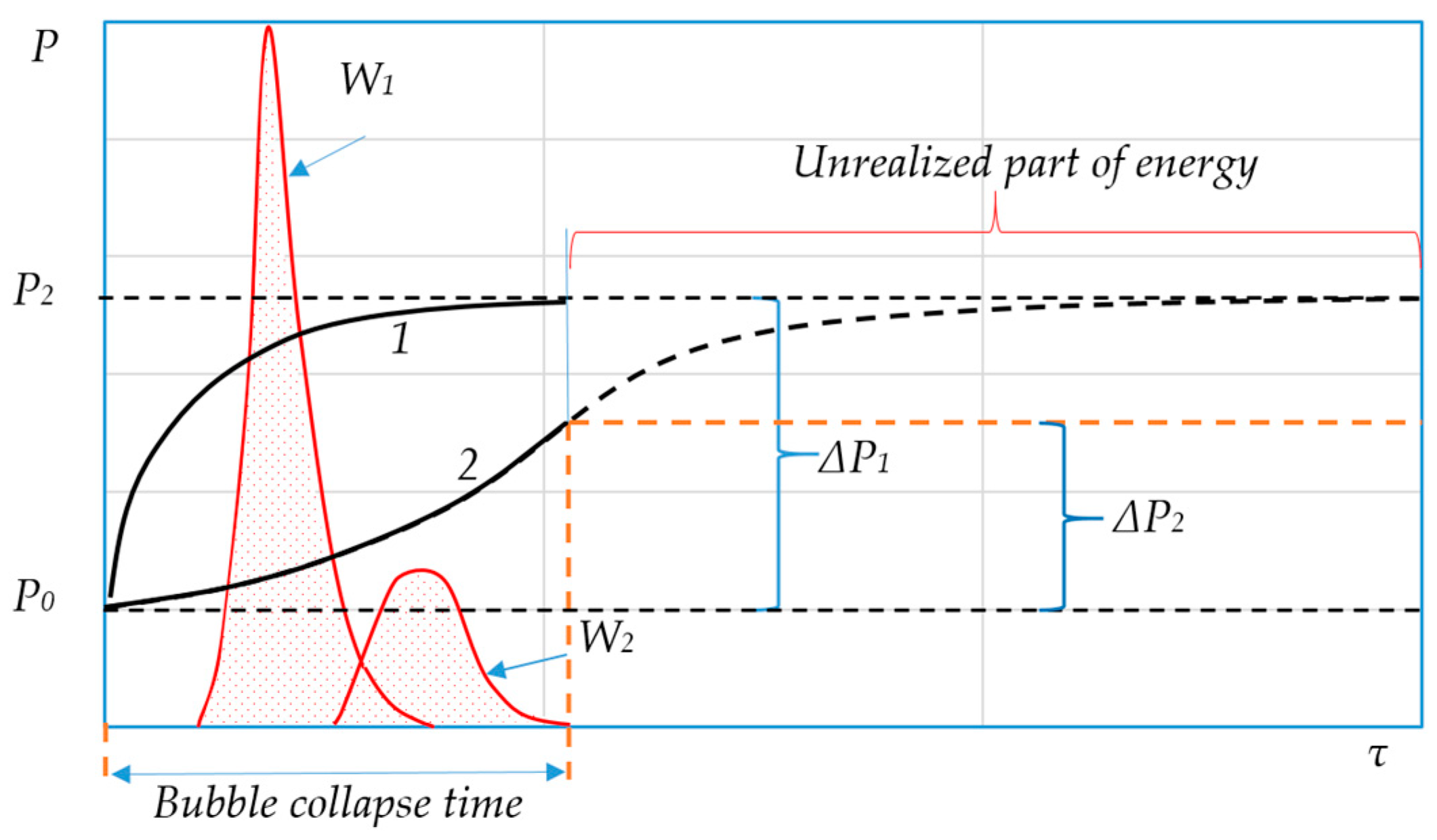
5.5.1. Sudden Increase in External Pressure

An increase in pressure in the liquid is equivalent to accumulating potential energy in the system:
E p o t = 4 3 π R 3 p l + 2 σ / R 0 p s a t T l 0
Under the action of a pressure difference, the bubble begins to contract. In the initial stage of compression, the inertia factor predominates, due to the pressure difference in the liquid and vapour phases. The system evolves in the direction of eliminating this factor by increasing the vapour pressure in the contracting bubble. Since the inequality p v > p s a t T l 0 is equivalent to μ v > μ l , instability arises, associated with the inequality of chemical potentials, which causes the intense condensation of vapour on the bubble wall. This, in turn, leads to the release of condensation heat and an increase in temperature in the adjacent layer of liquid to a value T s > T l 0 . Thermal instability initiates a non-equilibrium process of heat transfer from the bubble to the liquid. At the stage of bubble compression, thermal energy is transferred from the gas phase to the liquid phase due to the heat of condensation and interphase heat exchange, and the energy density reaches extremely high values, which is illustrated in Figure 5.
The figure shows that in the compression stage, most of the mechanical energy is irreversibly dissipated in the liquid in the form of heat, and in the expansion stage, only a small part of the heat is returned to the bubble and transformed into mechanical energy.
When the vapour pressure in the contracting bubble becomes equal to the external pressure, the kinetic energy of the radial motion of the liquid reaches its maximum. At the maximum compression of the bubble, the kinetic energy is transformed into the potential energy of the compressed gas and partially into the potential energy of the compressible liquid directly at the bubble wall. The latter is just the part of the energy that is irreversibly emitted into the liquid in the form of an acoustic pulse. The potential energy of the compressed vapour is again converted into the kinetic energy of the liquid motion, and the bubble begins to expand, but with a smaller energy reserve, taking into account acoustic and thermal losses. Before its final collapse, the bubble can undergo several decaying oscillations. Complete collapse occurs under the condition that all the vapour has condensed into the liquid.
The presence of oscillations in the collapsing bubble is determined by the fact that the relaxation time of thermal instability significantly exceeds the relaxation times of the accompanying non-equilibrium processes. The degree of attenuation of oscillations depends on the kinetics of heat and mass transfer through the interphase boundary.
Thus, the process of bubble collapse is controlled mainly by the mechanisms of inertial and interphase instability with very small relaxation times, which determines the rapid transformation of energy and the release of high-power energy in the form of a pulse.

5.5.2. Sharp Decrease in Fluid Pressure

Let us now consider the evolution of an equilibrium bubble in the case where the pressure in the liquid suddenly decreases from pl0 to p l < p l 0 . The amount of potential energy, which in this case is accumulated not in the liquid but inside the bubble, is still determined by expression (8). As in the previous case, the evolution of the bubble is determined by all three non-equilibrium processes. Due to the pressure difference, the bubble begins to expand intensively and the vapour pressure in the bubble very quickly decreases to the value of the external pressure. By this time, the potential energy of the vapour is completely converted into the kinetic energy of the liquid motion. Unlike the case of a contracting bubble, the energy is not concentrated in a local region but is distributed in the volume of the liquid. In accordance with Equation (4), as the radius of the bubble increases, w R , its growth rate should decrease.
The decrease in vapour pressure is compensated by rapid evaporation inside the bubble due to the difference in potentials, μ l μ v > 0 . This leads to a decrease in the surface temperature until the vapour pressure in the bubble becomes equal to the saturated vapour pressure at the surface temperature, p s a t T s , and simultaneously becomes equal to the liquid pressure, p l . When this condition is met, the short stage of inertial bubble growth is completed, during which the rapid transformation of the accumulated vapour energy into the kinetic energy of the liquid motion occurs.
The further evolution of the growing bubble is controlled by only one non-equilibrium process with potential T l T s > 0 , in which the thermal energy of the liquid is converted into the kinetic energy of the radial motion of the liquid. The vapour bubble acts as a transformer of such a transformation. Due to the extremely long relaxation time of this process, the monotonic growth of the bubble at this stage occurs in a quasi-stationary mode at d w R / d τ 0 and at constant values of T s and p v , which are determined from the condition p v p s a t T s p l . In a growing bubble, capillary forces associated with changes in the free surface energy counteract the movement of the bubble boundary, whereas in the previous case they contributed to its compression. When the pressure is released, there are no bubble oscillations. Increasing the temperature of the liquid provides a greater initial potential difference, p v p l , and a more powerful energy pulse will occur at the initial stage [28,127,128].
Even such a simplified analysis gives an idea of the important role that non-equilibrium thermodynamic processes play in the behaviour of bubble systems and the extent to which these processes are interconnected. Obviously, any theoretical approach to the problem of studying and predicting the mechanisms of local energy input should include the processes of heat and mass transfer, the kinetics of phase transitions, and hydrodynamic and capillary effects, which in turn opens up prospects for both improving technologies and for energy saving.

6. Efficiency Criteria for Local Energy Input Mechanisms

To break the equilibrium in the two-phase system of the liquid–vapour bubble and transfer it to a homogeneous liquid phase, it is enough to reduce the temperature or increase the pressure in the system (Figure 4). In the first case, thermal energy is accumulated in the system, and in the second case, mechanical energy is accumulated, but in any case, the bubble, when taken out of equilibrium, will immediately start to grow or shrink [189,190].
In this case, there is an accelerated radial movement of the liquid as a result of the transformation of the stored potential energy into kinetic energy [191,192]. This transformation of mechanical energy in the vicinity of a compressible bubble stops at the moment of bubble collapse, and from the point of view of the efficiency of the local energy input, it is desirable to concentrate possibly more energy in the bubble collapse zone at this moment. This means that even at the initial stage of bubble compression, a sufficient potential energy reserve must be accumulated.
Thus, the temporal dynamics of the system should be such that the duration of potential energy accumulation to a specified level is markedly shorter than the duration of its subsequent release. The latter is determined by the time of existence of the transforming element, the compressible bubble. It is clear that it is completely irrational to bring the system out of equilibrium by cooling or heating because of the slow accumulation of energy [193,194].
Therefore, a rapid change in pressure under this condition is the only way to initiate an effective energy supply.
Suppose that we have decided to use the energy released by bubbles at the moment of collapse (Figure 4) to achieve a certain hydromechanical effect, e.g., the destruction of emulsion droplets, and calculated the potential energy required for this and the corresponding pressure drop, Δpmax = 100 kPa, which can be provided, for example, by a fast-acting valve in a time interval of at least 5 ms.
Taking into account that the lifetime of a collapsing bubble is very short (for a bubble with a radius of 0.1 mm, it does not exceed 0.2 µs [189]), the bubble will collapse before the pressure reaches the required value, and as a result, only the small fraction of the specific potential energy that the system has managed to accumulate during the lifetime of the bubble, i.e., for 0.2 µs, is transformed into mechanical energy. Consequently, the desired effect cannot be achieved unless we can find a faster way to increase the pressure. This situation is schematically represented in Figure 6.
In the second case, the bubble does not have time to fully release the accumulated energy, Δp, before the final collapse, and the specific power is essentially small (W2 << W1).
If for the energy input, we use the dynamic characteristics of growing bubbles in the process of liquid boiling during a sudden pressure drop, the potential energy of the compressed vapour inside the bubble is converted into kinetic energy. This potential energy is stored in the process of external pressure release. Although the lifetime of a growing bubble is incomparably longer than that of a collapsing bubble, the dynamic characteristics of the bubble will be even higher in this case the faster the energy is accumulated. Figure 6 shows how the value of the specific power released in the pulse at the early stage of growth depends on the duration of pressure release.
The calculation was carried out using the mathematical model presented in [188,189] for the following conditions: R0 = 50 µm; T = 360 K; p1 = 71 kPa; and p2 = 20 kPa.
In turn, the duration of the mechanical energy conversion, Δτtr, should be very short in order to release the stored energy in the form of a maximum power pulse, W = ΔEaccτtr.
Regardless of the method used for the practical realisation of the local energy input, the following defining performance criteria must be met to achieve the optimum level of intensification.
(1)
The rate of potential energy accumulation should exceed the rate of its subsequent conversion into kinetic energy. When using bubbles as energy transformers, this condition is reduced to the requirement to ensure the maximum pressure difference between the phases in the shortest possible time and can be written in the following form:
d p 1 p 2 d τ max ; τ a c c < τ t r .
(2)
The duration of the energy transformation should be extremely short since the useful power released as a pulse is directly proportional to the value of the stored energy and inversely proportional to the transformation time. This condition boils down to the requirement to achieve extremely high values for the velocity and acceleration of the radial motion of the fluid:
d E k d τ max   or   d v R d τ max   and   v R max .
(3)
Energy in the form of a pulse must be released simultaneously in a large number of small local zones, evenly located throughout the working volume of the apparatus.
Simultaneous fulfilment of these basic conditions ensures the release of the maximum amount of energy. In solving specific practical problems, these conditions are necessary criteria that should be used to select the most efficient and rational method for local energy input.

7. Advantages of Localised Energy Input in Terms of Energy Savings

Many technologies and apparatuses are already in use in industry, in which the processes described in this paper are realised. It is obvious that the application of the concept of localised energy input opens up the possibility of improving these devices. The operating principles of these apparatuses are discussed in detail in various works: static mixers [195,196,197,198,199], mechanical stirrers [200,201,202,203], colloid mills [204,205,206], jet whistles [207,208], valve homogenisers [209,210,211], ultrasonic homogenisers [212,213,214], vacuum homogenisers [215,216,217], and others. At the same productivity and comparable efficiency, they differ from traditional analogues in terms of their small dimensions and metal consumption, simplicity of construction, and the duration of continuous operation. The main advantage of these apparatuses is their ability to achieve higher efficiency. The comparatively low energy consumption of such apparatuses is explained by a fundamentally different approach to intensifying processes in dispersed media, alternatively to the generally accepted concept of energy input.
Davies [218,219] analysed the applicability of the Kolmogorov–Hinze theory of local isotropic turbulence to predict the degree of emulsion droplet fragmentation in traditional dispersing apparatus of various classes. After summarising a large amount of experimental data from different authors on the dispersing power of various apparatuses, ranging from propeller stirrers and mixers to valve homogenisers and ultrasonic generators, Davies found a correlation between the maximum droplet diameter, dmax, and the value of the dissipation power per unit mass, Wm, in the range of 5 to 109 W/kg. The value of Wm refers to the active zone of the apparatus where the maximum dissipation of energy occurs. It was found that the experimental data were satisfactorily described by the theoretical dependence d max = C σ / ρ c 0.6 W m 0.4 over the whole lg d max = f lg W m range of Wm values studied. As Davis shows, the experimental dependence is a straight line with a slope of −0.4.
We carried out similar calculations using the Davis method as an example for dispersing devices developed on the basis of the principle of local energy input. It was found that for all devices of this type, the appropriate level of dispersion is achieved at significantly lower (by 2–3 orders of magnitude) values of the dissipated power, Wm, in the core. Figure 7 shows the experimental dependence, lgdmax = f(lgWm), of conventional dispersing devices.
The effectiveness of using local energy input in various technologies can be estimated from Figure 7. With the same technological effects, we see differences in energy consumption in different processes. For example, in order to obtain a dispersed medium with an average phase size of 5 µm, colloid mill methods, homogenizer valves, or ultrasonic homogenization can be used. However, the energy costs for the implementation of this task will be significantly different. Compared with the local pulsed energy input, homogenizer valves will consume about 10 times more energy. It is fundamentally important that the other methods presented in Figure 7 will not allow the specified value of the parameter to be achieved, even with infinitely large energy costs. In general, the efficiency of methods is not only determined by technological processes, but it also, to a large extent, depends on the efficiency of devices. Therefore, a generalised correct assessment of efficiency can be made only by analysing specific devices.
The presented results confirm the fundamental difference between apparatuses with local energy transformation and traditional ones and emphasise the fact that the use of input energy in these apparatuses is carried out at a qualitatively different level. On the other hand, understanding the mechanisms of energy input and transformation will improve the efficiency of these technologies.

8. Conclusions

The analysis of traditional methods of intensifying technological processes in dispersed media reveals the advantages and expediency of local energy input into the apparatus in the form of discretely distributed short-term pulses in the volume of the working medium. However, the spatial and temporal discretisation of the input energy resulting from the initiation of the developed turbulence in the continuous phase of a dispersed medium for the purpose of intensifying heat and mass exchange processes leads to an increase in unproductive energy consumption. Furthermore, an analysis of methods for intensifying hydromechanical processes in disperse media has revealed the limitations of employing the theory of local isotropic turbulence to analyse the mechanisms behind the hydromechanical destruction of disperse particles. Consequently, local energy input emerges as an alternative approach to intensifying processes in disperse media, offering the potential to achieve a high level of intensification of mass exchange and hydromechanical processes while minimising unproductive energy consumption.
A comprehensive review of the existing literature has enabled the formulation of general criteria for the efficiency of physical mechanisms of energy input in relation to their use for the intensification of technological processes. It is evident that the control of local energy input processes has the potential to enhance the efficiency of technologies and apparatuses. However, this objective will require further research efforts directed towards the study of local energy transformation mechanisms.

Funding

This research received no external funding.

Conflicts of Interest

The author declares no conflict of interest.

References

  1. Fatras, N.; Ma, Z.; Jorgensen, B.N. Process-to-market matrix mapping: A multi-criteria evaluation framework for industrial processes’ electricity market participation feasibility. Appl. Energy 2022, 313, 118829. [Google Scholar] [CrossRef]
  2. Yan, C.; Geng, X.; Bie, Z.; Xiec, L. Two-stage robust energy storage planning with probabilistic guarantees: A data-driven approach. Appl. Energy 2022, 313, 118623. [Google Scholar] [CrossRef]
  3. Ostergaard, J.; Ziras, C.; Bindner, H.W.; Kazempour, J.; Marinelli, M.; Markussen, P.; Rosted, S.H.; Christensen, J.S. Energy Security Through Demand-Side Flexibility: The Case of Denmark. IEEE Power Energy Mag. 2021, 19, 46–55. [Google Scholar] [CrossRef]
  4. Hongbo, C.; Kaile, Z. Industrial power load scheduling considering demand response. J. Clean. Prod. 2018, 204, 447–460. [Google Scholar]
  5. Gils, H.C. Assessment of the theoretical demand response potential in Europe. Energy 2014, 67, 1–18. [Google Scholar] [CrossRef]
  6. Moritz, P.; Frieder, F. The potential of demand-side management in energy-intensive industries for electricity markets in Germany. Appl. Energy 2011, 88, 432–441. [Google Scholar]
  7. Sklabinsky, V.; Pavlenko, I. Intensification of mass transfer processes through the impact of the velocity gradient on hydrodynamics and stability of liquid droplets in a gas flow. Chem. Eng. Sci. 2021, 235, 116470. [Google Scholar] [CrossRef]
  8. Sharma, A.K.; Bhandari, R.; Pinca-Bretotean, C.; Sharma, C.; Dhakad, S.K.; Mathur, A. A study of trends and industrial prospects of Industry 4.0. Mater. Today Proc. 2021, 47, 2364–2369. [Google Scholar] [CrossRef]
  9. Mohan, S.; Katakojwala, R. The circular chemistry conceptual framework: A way forward to sustainability in industry 4.0. Curr. Opin. Green Sustain. Chem. 2021, 28, 100434. [Google Scholar] [CrossRef]
  10. Hofmann, M.; Bayles, A.V.; Vermant, J. Stretch, fold, and break: Intensification of emulsification of high viscosity ratio systems by fractal mixers. AIChE J. 2021, 67, e17192. [Google Scholar] [CrossRef]
  11. López-Guajardo, E.A.; Delgado-Licona, F.; Álvarez, A.J.; Nigam, K.D.; Montesinos-Castellanos, A.; Morales-Menendez, R. Process intensification 4.0: A new approach for attaining new, sustainable and circular processes enabled by machine learning. Chem. Eng. Process.-Process Intensif. 2022, 180, 108671. [Google Scholar] [CrossRef]
  12. Volk, A.A.; Epps, R.W.; Abolhasani, M. Accelerated development of colloidal nanomaterials enabled by modular microfluidic reactors: Toward autonomous robotic experimentation. Adv. Mater. 2021, 33, 2004495. [Google Scholar] [CrossRef] [PubMed]
  13. Wang, L.; Karadaghi, L.R.; Brutchey, R.L.; Malmstadt, N. Self-optimizing parallel millifluidic reactor for scaling nanoparticle synthesis. Chem. Commun. 2020, 56, 3745–3748. [Google Scholar] [CrossRef]
  14. Kleiner, J.; Hinrichsen, O. Epoxidation of methyl oleate in a rotor-stator spinning disc reactor. Chem. Eng. Process.-Process Intensif. 2019, 136, 152–162. [Google Scholar] [CrossRef]
  15. Manzano Martínez, A.N.; van Eeten, K.M.; Schouten, J.C.; van der Schaaf, J. Micromixing in a rotor–stator spinning disc reactor. Ind. Eng. Chem. Res. 2017, 56, 13454–13460. [Google Scholar] [CrossRef]
  16. Toma, H.; Nishino, K. Convective mixing of miscible liquids in a rotor-stator spinning disk reactor. Chem. Eng. J. 2017, 346, 329–339. [Google Scholar] [CrossRef]
  17. Ferrouillat, S.; Tochon, P.; Garnier, C.; Peerhossaini, H. Intensification of heat-transfer and mixing in multifunctional heat exchangers by artificially generated streamwise vorticity. Appl. Therm. Eng. 2006, 26, 1820–1829. [Google Scholar] [CrossRef]
  18. Keil, F.J. Process intensification. Rev. Chem. Eng. 2017, 34, 135–200. [Google Scholar] [CrossRef]
  19. Ohmura, N.; Masuda, H.; Wang, S. Intensification of Mixing Processes with Complex Fluids. J. Chem. Eng. Jpn. 2018, 51, 129–135. [Google Scholar] [CrossRef]
  20. Elayarani, M.; Shanmugapriya, M.; Senthil Kumar, P. Intensification of heat and mass transfer process in MHD carreau nanofluid flow containing gyrotactic microorganisms. Chem. Eng. Process.-Process Intensif. 2021, 160, 108299. [Google Scholar] [CrossRef]
  21. Law, R.; Ramshaw, C.; Reay, D. Process intensification—Overcoming impediments to heat and mass transfer enhancement when solids are present, via the IbD project. Therm. Sci. Eng. Prog. 2017, 1, 53–58. [Google Scholar] [CrossRef]
  22. Jin, Y.; Zhao, W.; Li, Z. Effect of Gas-Liquid Contact Intensification on Heat and Mass Transfer in Deflector and Rod Bank Desulfurization Spray Tower. Processes 2021, 9, 1269. [Google Scholar] [CrossRef]
  23. Wang, P.; Dai, G. Field Synergy of the Rod Bank on the Enhancement of Mass Transfer in a Spray Column. Ind. Eng. Chem. Res. 2018, 57, 12531–12542. [Google Scholar] [CrossRef]
  24. Wang, Z.; Yang, T.; Liu, Z.; Wang, S.; Gao, Y.; Wu, M. Mass Transfer in a Rotating Packed Bed: A Critical Review. Chem. Eng. Process.-Process Intensif. 2019, 139, 78–94. [Google Scholar] [CrossRef]
  25. Bangerth, S.; Tiwari, R.; Shooshtari, A.; Ohadi, M. Process intensification in a spinning disk absorber for absorption heat pumps. Appl. Therm. Eng. 2019, 162, 114179. [Google Scholar] [CrossRef]
  26. Boodhoo, K.V.K.; Jachuck, R.J. Process intensification: Spinning disk reactor for styrene polymerisation. Appl. Therm. Eng. 2000, 20, 1127–1146. [Google Scholar] [CrossRef]
  27. Basok, B.; Davydenko, B.; Pavlenko, A.M. Numerical Network Modeling of Heat and Moisture Transfer through Capillary-Porous Building Materials. Materials 2021, 14, 1819. [Google Scholar] [CrossRef]
  28. Pavlenko, A. Energy conversion in heat and mass transfer processes in boiling emulsions. Therm. Sci. Eng. Prog. 2020, 15, 100439. [Google Scholar] [CrossRef]
  29. Adibi, O.; Rashidi, S.; Abolfazli Esfahani, J. Effects of perforated anchors on heat transfer intensification of turbulence nanofluid flow in a pipe. J. Therm. Anal. Calorim. 2020, 141, 2047–2059. [Google Scholar] [CrossRef]
  30. De Beer, M.M.; Loane, L.P.M.; Keurentjes, J.T.F.; Schouten, J.C.; van der Schaaf, J. Single phase fluid-stator heat transfer in a rotor–stator spinning disc reactor. Chem. Eng. Sci. 2014, 119, 88–98. [Google Scholar] [CrossRef]
  31. Haseidl, F.; Pottbäcker, J.; Hinrichsen, O. Gas–Liquid mass transfer in a rotor–stator spinning disc reactor: Experimental study and correlation. Chem. Eng. Process. Process Intensif. 2016, 104, 181–189. [Google Scholar] [CrossRef]
  32. Zhang, J.; Teixeira, A.R.; Zhang, H.; Jensen, K.F. Determination of fast gas–liquid reaction kinetics in flow. React. Chem. Eng. 2020, 5, 51–57. [Google Scholar] [CrossRef]
  33. Hu, B.; Li, X.; Fu, Y.; Zhang, F.; Gu, C.; Ren, X.; Wang, C. Experimental investigation on the flow and flow-rotor heat transfer in a rotor-stator spinning disk reactor. Appl. Therm. Eng. 2019, 162, 114316. [Google Scholar] [CrossRef]
  34. De Beer, M.M.; Keurentjes, J.T.; Schouten, J.C.; van der Schaaf, J. Intensification of convective heat transfer in a stator–rotor–stator spinning disc reactor. AIChE J. 2015, 61, 2307–2318. [Google Scholar] [CrossRef]
  35. Yang, P.; Li, X.; Li, H.; Cong, H.; Kiss, A.A.; Gao, X. Unraveling the influence of residence time distribution on the performance of reactive distillation–Process optimization and experimental validation. Chem. Eng. Sci. 2021, 237, 116559. [Google Scholar] [CrossRef]
  36. Pavlenko, A.M.; Basok, B.I.; Avramenko, A.A. Heat conduction of a multi-layer disperse particle of emulsion. Heat Transf. Res. 2005, 36, 55–61. [Google Scholar] [CrossRef]
  37. Lloyd, D.M.; Norton, I.T.; Spyropoulos, F. Process optimisation of rotating membrane emulsification through the study of surfactant dispersions. J. Food Eng. 2015, 166, 316–324. [Google Scholar] [CrossRef]
  38. Atkins, M.D.; Kienhöfer, F.W.; Kang, K.; Lu, T.J.; Kim, T. Cooling Mechanisms in a Rotating Brake Disc with a Wire-Woven-Bulk Diamond Cellular Core. ASME. J. Thermal Sci. Eng. Appl. 2021, 13, 041006. [Google Scholar] [CrossRef]
  39. Atkins, M.D.; Kienhöfer, F.W.; Lu, T.J.; Kim, T. Local Heat Transfer Distributions Within a Rotating Pin-Finned Brake Disk, ASME. J. Heat Transf. 2020, 142, 112101. [Google Scholar] [CrossRef]
  40. Steurer, A.; Poser, R.; von Wolfersdorf, J.; Retzko, S. Application of the Transient Heat Transfer Measurement Technique Using Thermochromic Liquid Crystals in a Network Configuration with Intersecting Circular Passages, ASME. J. Turbomach. 2019, 141, 051010. [Google Scholar] [CrossRef]
  41. Mitkowski, P.T.; Szaferski, W. Production of emulsion in tank mixer with sieve bottom. Chem. Eng. Res. Des. 2016, 109, 618–627. [Google Scholar] [CrossRef]
  42. Jadhav, A.J.; Ferraro, G.; Barigou, M. Generation of Bulk Nanobubbles Using a High-Shear Rotor–Stator Device. Ind. Eng. Chem. Res. 2021, 60, 8597–8606. [Google Scholar] [CrossRef]
  43. Li, W.; Xia, F.; Zhao, S.; Guo, J.; Zhang, M.; Li, W.; Zhang, J. Mixing Performance of an Inline High-Shear Mixer with a Novel Pore-Array Liquid Distributor. Ind. Eng. Chem. Res. 2019, 58, 20213–20225. [Google Scholar] [CrossRef]
  44. Kwon, C.; Pak, U.S.; Kim, C.M.; Paek, C.H. CFD analysis of flow field and power consumption of in-line high shear mixers with different stator structures. J. Indian Chem. Soc. 2021, 98, 100159. [Google Scholar] [CrossRef]
  45. Li, X.; Yang, L.; Guo, J.; Li, W.; Zhou, M.; Zhang, J. Micromixing performance of the teethed high shear mixer under semi-batch operation. Front. Chem. Sci. Eng. 2021, 16, 546–559. [Google Scholar] [CrossRef]
  46. Liu, Y.; Guo, J.; Li, W.; Li, W.; Zhang, J. Investigation of gas-liquid mass transfer and power consumption characteristics in jet-flow high shear mixers. Chem. Eng. J. 2021, 411, 128580. [Google Scholar] [CrossRef]
  47. Yang, L.; Li, W.; Guo, J.; Li, W.; Wang, B.; Zhang, M.; Zhang, J. Effects of rotor and stator geometry on dissolution process and power consumption in jet-flow high shear mixers. Front. Chem. Sci. Eng. 2021, 15, 384–398. [Google Scholar] [CrossRef]
  48. Vashisth, V.; Nigam, K.; Kumar, V. Design and development of high shear mixers: Fundamentals, applications and recent progress. Chem. Eng. Sci. 2021, 232, 116296. [Google Scholar] [CrossRef]
  49. Kwon, C.; Song, U.; Pak, U.; Kim, C.; Kim, K.-C. Effect of structural parameters on the flow field and power consumption of in-line high shear mixer. J. Indian Chem. Soc. 2021, 98, 100042. [Google Scholar] [CrossRef]
  50. Kwon, C.; Kim, K.; Pak, U. Effect of the stator tooth thickness on flow characteristics of high shear mixer. J. Phys. Conf. Ser. 2021, 1750, 012026. [Google Scholar] [CrossRef]
  51. Espinoza, C.J.U.; Alberini, F.; Mihailova, O.; Kowalski, A.J.; Simmons, M.J.H. Flow, turbulence and potential droplet break up mechanisms in an in-line Silverson 150/250 high shear mixer. Chem. Eng. Sci. X 2020, 6, 100055. [Google Scholar] [CrossRef]
  52. Lv, Y.; Ye, C.; Zhang, J.; Guo, C. Rapid and efficient synthesis of highly crystalline SSZ-13 zeolite by applying high shear mixing in the aging process. Microporous Mesoporous Mater. 2020, 293, 109812. [Google Scholar] [CrossRef]
  53. Municchi, F.; Nagrani, P.P.; Christov, I.C. A two-fluid model for numerical simulation of shear-dominated suspension flows. Int. J. Multiph. Flow 2019, 120, 103079. [Google Scholar] [CrossRef]
  54. Snider, R.F. Irreversible thermodynamics of multicomponent fluids and its statistical mechanics basis. Phys. Rev. 2021, 103, 032121. [Google Scholar] [CrossRef] [PubMed]
  55. Beris, A.N.; Jariwala, S.; Wagner, N.J. Flux-based modeling of heat and mass transfer in multicomponent systems. Phys. Fluids 2022, 34, 033113. [Google Scholar] [CrossRef]
  56. Gondrexon, N.; Cheze, L.; Jin, Y.; Legay, M.; Tissot, Q.; Hengl, N.; Baup, S.; Boldo, P.; Pignon, F.; Talansier, E. Intensification of heat and mass transfer by ultrasound: Application to heat exchangers and membrane separation processes. Ultrason. Sonochem. 2015, 25, 40–50. [Google Scholar] [CrossRef]
  57. Chen, B.; Wan, Z.; Chen, G.; Zhong, G.; Tang, Y. Improvement of ultrasonic heat transfer enhancement using acoustical focusing and resonance properties. Int. Commun. Heat Mass Transf. 2019, 104, 60–69. [Google Scholar] [CrossRef]
  58. Peñas, P.; Soto, Á.M.; Lohse, D.; Lajoinie, G.; van der Meer, D. Ultrasound-enhanced mass transfer during the growth and dissolution of surface gas bubbles. Int. J. Heat Mass Transf. 2021, 174, 121069. [Google Scholar] [CrossRef]
  59. Pavlenko, A.; Koshlak, H. Application of Thermal and Cavitation Effects for Heat and Mass Transfer Process Intensification in Multicomponent Liquid Media. Energies 2021, 14, 7996. [Google Scholar] [CrossRef]
  60. Mao, Y.; Robinson, J.; Binner, E. Understanding heat and mass transfer processes during microwave-assisted and conventional solvent extraction. Chem. Eng. Sci. 2021, 233, 116418. [Google Scholar] [CrossRef]
  61. Lee, C.S.; Binner, E.; Winkworth-Smith, C.; John, R.; Gomes, R.; Robinson, J. Enhancing natural product extraction and mass transfer using selective microwave heating. Chem. Eng. Sci. 2016, 149, 97–103. [Google Scholar] [CrossRef]
  62. Foukrach, M.; Bouzit, M.; Ameur, K.Y. Effect of Agitator’s Types on the Hydrodynamic Flow in an Agitated Tank. Chin. J. Mech. Eng. 2020, 33, 37. [Google Scholar] [CrossRef]
  63. Zhang, P.; Chen, G.-H.; Duan, J.-H.; Wang, W.-W. Mixing characteristics in a vessel equipped with cylindrical stirrer. Results Phys. 2018, 10, 699–705. [Google Scholar] [CrossRef]
  64. Feng, X.; Cheng, J.; Li, X.; Yang, C.; Mao, Z.S. Numerical simulation of turbulent flow in a baffled stirred tank with an explicit algebraic stress model. Chem. Eng. Sci. 2012, 69, 30–44. [Google Scholar] [CrossRef]
  65. Kamla, Y.; Bouzit, M.; Hadjeb, A.; Arab, I.M.; Beloudane, M. CFD study of the effect of Baffles on the energy consumption and the flow structure in a vessel stirred by a Rushton turbine. Mechanika 2016, 22, 190–197. [Google Scholar] [CrossRef]
  66. Ascanio, G. Mixing time in stirred vessels: A review of experimental techniques. Chin. J. Chem. Eng. 2015, 23, 1065–1076. [Google Scholar] [CrossRef]
  67. Ameur, H. Mixing of complex fluids with flat and pitched bladed impellers: Effect of blade attack angle and shear-thinning behavior. Food Bioprod. Process. 2016, 99, 71–77. [Google Scholar] [CrossRef]
  68. Heyter, A.; Wollny, S. Influence of different baffle variations on the effectiveness of multi-stage agitated vessels. Chem. Ing. Tech. 2017, 89, 416–423. [Google Scholar] [CrossRef]
  69. Hu, L.; Zhu, H.; Hua, J. DEM simulation of energy transitions in a hammer mill: Effect of impeller configurations, agitation speed, and fill level. Powder Technol. 2021, 394, 1077–1093. [Google Scholar] [CrossRef]
  70. Pang, H.; Ngaile, G. Modeling of a valve-type low-pressure homogenizer for oil-in-water emulsions. Chem. Eng. Process.-Process Intensif. 2021, 160, 108249. [Google Scholar] [CrossRef]
  71. Yadav, K.S.; Kale, K. High Pressure Homogenizer in Pharmaceuticals: Understanding Its Critical Processing Parameters and Applications. J. Pharm. Innov. 2020, 15, 690–701. [Google Scholar] [CrossRef]
  72. Taghinia, J.; Rahman, M.; Tse, T.K.; Siikonen, T. CFD modeling of homogenizer valve: A comparative study. Chem. Eng. Res. Des. 2016, 106, 327–336. [Google Scholar] [CrossRef]
  73. Pang, H.; Ngaile, G. Utilization of Secondary Jet in Cavitation Peening and Cavitation Abrasive Jet Polishing. Micromachines 2022, 13, 86. [Google Scholar] [CrossRef] [PubMed]
  74. Liang, X.-X.; Linz, N.; Freidank, S.; Paltauf, G.; Vogel, A. Comprehensive analysis of spherical bubble oscillations and shock wave emission in laser-induced cavitation. J. Fluid Mech. 2022, 940, A5. [Google Scholar] [CrossRef]
  75. Ho, D.S.; Scialabba, D.; Terry, R.S.; Ma, X.; Chen, J.; Sankin, G.N.; Xiang, G.; Qi, R.; Preminger, G.M.; Lipkin, M.E.; et al. The Role of Cavitation in Energy Delivery and Stone Damage During Laser Lithotripsy. J. Endourol. 2021, 35, 860–870. [Google Scholar] [CrossRef] [PubMed] [PubMed Central]
  76. Wang, D.; Bi, Y. Investigation of the influence of different liquid temperatures on the dynamics of long-pulse laser-induced cavitation bubbles. AIP Adv. 2024, 14, 025013. [Google Scholar] [CrossRef]
  77. Zhang, Z.; Wei, S.; Wang, P.; Qiu, W.; Zhang, G. Progress in applications of laser induced cavitation on surface processing. Opt. Laser Technol. 2024, 170, 110212. [Google Scholar] [CrossRef]
  78. Schoppink, J.J.; Krizek, J.; Moser, C.; Rivas, D.F. Cavitation induced by pulsed and continuous-wave fiber lasers in confinement. Exp. Therm. Fluid Sci. 2023, 146, 110926. [Google Scholar] [CrossRef]
  79. Tiang, S.S.L.; Low, L.E.; Ali, I.; Zhou, L.; Goh, B.-H.; Gew, L.T.; Tang, S.Y. Recent advances in ultrasonic cavitation technologies for emulsion preparation: A mini review. Curr. Opin. Chem. Eng. 2024, 45, 101046. [Google Scholar] [CrossRef]
  80. Tiong, T.; Chu, J.K.; Tan, K.W. Advancements in Acoustic Cavitation Modelling: Progress, Challenges, and Future Directions in Sonochemical Reactor Design. Ultrason. Sonochem. 2025, 112, 107163. [Google Scholar] [CrossRef]
  81. Guo, D.-S.; Li, X.-B.; Zhang, H.-N.; Li, F.-C.; Ming, P.-J.; Oishi, M.; Oshima, M. Experimental study on the characteristics of temperature dependent surface/interfacial properties of a non-ionic surfactant aqueous solution at quasi-thermal equilibrium condition. Int. J. Heat Mass Transf. 2022, 182, 122003. [Google Scholar] [CrossRef]
  82. Wang, J.; Li, F.-C.; Li, X.-B. On the mechanism of boiling heat transfer enhancement by surfactant addition. Int. J. Heat Mass Transf. 2016, 101, 800–806. [Google Scholar] [CrossRef]
  83. Takeyama, M.; Zupančič, M.; Kunugi, T. Influence of hydrodynamic interactions among multiple bubbles on convective heat transfer in nucleate boiling. Exp. Therm. Fluid Sci. 2021, 128, 110449. [Google Scholar] [CrossRef]
  84. Sergi, D.; Scocchi, G.; Ortona, A. Molecular dynamics simulations of the contact angle between water droplets and graphite surfaces. Fluid Phase Equilibria 2012, 332, 173–177. [Google Scholar] [CrossRef]
  85. Feraco, F.; Marino, R.; Primavera, L.; Pumir, A.; Mininni, P.D.; Rosenberg, D.; Pouquet, A.; Foldes, R.; Lévêque, E.; Camporeale, E.; et al. Connecting Large-Scale Velocity and Temperature Bursts with Small-Scale Intermittency in Stratified Turbulence. EPL 2021, 135, 14001. [Google Scholar] [CrossRef]
  86. Brůha, T.; Procházka, P.; Uruba, V. Investigation of Low-Frequency Phenomena within Flow Pattern in Standard Mixing Vessel Induced by Pitched Blade Impeller. Processes 2021, 9, 545. [Google Scholar] [CrossRef]
  87. Pozorski, J.; Wacławczyk, M. Mixing in Turbulent Flows: An Overview of Physics and Modelling. Processes 2020, 8, 1379. [Google Scholar] [CrossRef]
  88. Gomaa, H.G.; Taweel, A.M.A. Intensification of inter-phase mass transfer: The combined effect of oscillatory motion and turbulence promoters. Heat Mass Transf. 2007, 43, 371. [Google Scholar] [CrossRef]
  89. Zaki, M.; Abdel-Aziz, M.H.; Nirdosh, I.; Sedahmed, G.H. Intensification of the rate of heat and mass transfer in a batch and continuous parallel plate contactor by pulsed flow. Chem. Eng. J. 2020, 398, 125589. [Google Scholar] [CrossRef]
  90. He, F.; Dong, W.; Wang, J. Modeling and Numerical Investigation of Transient Two-Phase Flow with Liquid Phase Change in Porous Media. Nanomaterials 2021, 11, 183. [Google Scholar] [CrossRef]
  91. Kolmogorov, A.N. Dissipation of Energy in the Locally Isotropic Turbulence. Proc. R. Soc. London. Ser. A Math. Phys. Sci. 1991, 434, 15–17. [Google Scholar] [CrossRef]
  92. McComb, W.D. A local energy-transfer theory of isotropic turbulence. J. Phys. A Math. Nucl. Gen. 2001, 7, 632. [Google Scholar] [CrossRef]
  93. Osawa, K.; Naka, Y.; Fukushima, N.; Shimura, M.; Tanahashi, M.; Miyauchi, T. Effect of Flow Structures on Turbulence Statistics of Taylor-Couette Flow in the Torque Transition State. Flow Turbul. Combust 2016, 97, 973–986. [Google Scholar] [CrossRef]
  94. Takaoka, M.; Yokoyama, N.; Sasaki, E. Local-flux vectors of conserved quantities in wavenumber space: Anisotropic structures in Charney–Hasegawa–Mima turbulence. Phys. Rev. Fluids 2022, 7, L012601. [Google Scholar] [CrossRef]
  95. Dodd, M.S.; Jofre, L. Small-scale flow topologies in decaying isotropic turbulence laden with finite-size droplets. Phys. Rev. Fluids 2019, 4, 064303. [Google Scholar] [CrossRef]
  96. Portwood, G.; Kops, S.d.B.; Caulfield, C. Implications of inertial subrange scaling for stably stratified mixing. J. Fluid Mech. 2022, 939, A10. [Google Scholar] [CrossRef]
  97. Lang, C.J.; Waite, M.L. Scale-dependent anisotropy in forced stratified turbulence. Phys. Rev. Fluids 2019, 4, 044801. [Google Scholar] [CrossRef]
  98. Ren, Y.; Zhang, H.; Zhang, X.; Li, Q.; Cai, X.; Song, Y.; Kang, L.; Zhu, T. Temporal and spatial characteristics of turbulent transfer and diffusion coefficient of PM2. 5. Sci. Total Environ. 2021, 782, 146804. [Google Scholar] [CrossRef]
  99. Ohsawa, A.; Murata, A.; Iwamoto, K. Contribution of advetion, turbulent transport and diffusion terms to Nusselt number and torque coefficient in Taylor-Couette flow. J. Therm. Sci. Technol. 2016, 11, JTST0027. [Google Scholar] [CrossRef]
  100. Brouwers, J.J.H. Statistical Model of Turbulent Dispersion Recapitulated. Fluids 2021, 6, 190. [Google Scholar] [CrossRef]
  101. Nouri, L.; Abouda, L.; Legrand, J. Estimation of the micromixing time in the torus reactor by the application of the incorporation model. Chem. Eng. Process. Process Intensif. 2014, 78, 37–43. [Google Scholar] [CrossRef]
  102. Ouyang, Y.; Manzano, M.N.; Wetzels, R.; Chen, S.; Lang, X.; Heynderickx, G.J.; Van Geem, K.M. Liquid hydrodynamics in a gas-liquid vortex reactor. Chem. Eng. Sci. 2021, 246, 116970. [Google Scholar] [CrossRef]
  103. Martínez, A.N.M.; Jansen, R.; Walker, K.; Assirelli, M.; van der Schaaf, J. Experimental and modeling study on meso- and micromixing in the rotor–stator spinning disk reactor. Chem. Eng. Res. Des. 2021, 173, 279–288. [Google Scholar] [CrossRef]
  104. Tao, R.; Wang, Z. Comparative numerical studies for the flow energy dissipation features in a pump-turbine in pump mode and turbine mode. J. Energy Storage 2021, 41, 102835. [Google Scholar] [CrossRef]
  105. Lu, Z.; Xiao, R.; Tao, R.; Li, P.; Liu, W. Influence of guide vane profile on the flow energy dissipation in a reversible pump-turbine at pump mode. J. Energy Storage 2022, 49, 104161. [Google Scholar] [CrossRef]
  106. De Beer, M.M.; Keurentjes, J.T.F.; Schouten, J.C.; Van der Schaaf, J. Bubble formation in co-fed gas–liquid flows in a rotor-stator spinning disc reactor. Int. J. Multiph. Flow 2016, 83, 142–152. [Google Scholar] [CrossRef]
  107. Manzano Martinez, A.N.; Chaudhuri, A.; Besten, M.; Assirelli, M.; van der Schaaf, J. Micromixing Efficiency in the Presence of an Inert Gas in a Rotor–Stator Spinning Disk Reactor. Ind. Eng. Chem. Res. 2021, 60, 8677–8686. [Google Scholar] [CrossRef]
  108. Hinze, J.O. Fundamentals of the hydrodynamic mechanism of splitting in dispersion processes. AIChE J. 1955, 1, 289–295. [Google Scholar] [CrossRef]
  109. Foronda-Trillo, F.; Rodríguez-Rodríguez, J.; Gutiérrez-Montes, C.; Martínez-Bazán, C. Deformation and breakup of bubbles interacting with single vortex rings. Int. J. Multiph. Flow 2021, 142, 103734. [Google Scholar] [CrossRef]
  110. Hasan, B.O.; Hamad, M.F.; Majdi, H.S.; Hathal, M.M. Experimental characterization of dynamic behavior of single bubble breakage in an agitated tank. Eur. J. Mech.-B/Fluids 2021, 85, 430–443. [Google Scholar] [CrossRef]
  111. Zhang, H.; Wang, Y.; Sayyar, A.; Wang, T. Experimental study on breakup of a single bubble in a stirred tank: Effect of gas density and liquid properties. AIChE J. 2021, 69, e17511. [Google Scholar] [CrossRef]
  112. Mutsch, B.; Preiss, F.J.; Dagenbach, T.; Karbstein, H.P.; Kähler, C.J. Scaling of Droplet Breakup in High-Pressure Homogenizer Orifices. Part II: Visualization of the Turbulent Droplet Breakup. Chem. Eng. 2021, 5, 31. [Google Scholar] [CrossRef]
  113. Wang, Z.; Hopfes, T.; Giglmaier, M.; Adams, N.A. Experimental investigation of shock-induced tandem droplet breakup. Phys. Fluids 2021, 33, 012113. [Google Scholar] [CrossRef]
  114. Zhou, H.; Yu, X.; Wang, B.; Jing, S.; Lan, W.; Li, S. Breakup model of oscillating drops in turbulent flow field. Chem. Eng. Sci. 2021, 247, 117036. [Google Scholar] [CrossRef]
  115. Rosti, M.; Ge, Z.; Jain, S.; Dodd, M.; Brandt, L. Droplets in homogeneous shear turbulence. J. Fluid Mech. 2019, 876, 962–984. [Google Scholar] [CrossRef]
  116. Gallassi, M.; Gonçalves, G.F.; Botti, T.C.; Moura, M.J.; Carneiro, J.N.; Carvalho, M.S. Numerical and experimental evaluation of droplet breakage of O/W emulsions in rotor-stator mixers. Chem. Eng. Sci. 2019, 204, 270–286. [Google Scholar] [CrossRef]
  117. Soligo, G.; Roccon, A.; Soldati, A. Turbulent Flows with Drops and Bubbles: What Numerical Simulations Can Tell Us—Freeman Scholar Lecture. J. Fluids Eng. 2021, 143, 080801. [Google Scholar] [CrossRef]
  118. Crialesi-Esposito, M.; Rosti, M.; Chibbaro, S.; Brandt, L. Modulation of homogeneous and isotropic turbulence in emulsions. J. Fluid Mech. 2022, 940, A19. [Google Scholar] [CrossRef]
  119. Podgórska, W. The Influence of Internal Intermittency, Large Scale Inhomogeneity, and Impeller Type on Drop Size Distribution in Turbulent Liquid-Liquid Dispersions. Entropy 2019, 21, 340. [Google Scholar] [CrossRef]
  120. Han, L.; Gong, S.; Li, Y.; Gao, N.; Fu, J.; Luo, H.; Liu, Z. Influence of energy spectrum distribution on drop breakage in turbulent flows. Chem. Eng. Sci. 2014, 117, 55–70. [Google Scholar] [CrossRef]
  121. Philip, R.M.; Hewitt, I.J.; Howell, P.D. Modeling the Effect of Surfactant on Droplet Breakup in a Turbulent Flow. J. Appl. Math. 2021, 81, 129–152. [Google Scholar] [CrossRef]
  122. Zhou, H.; Tang, X.; Zhu, Z.; Li, S. 0D Homogeneous Simulation of Droplet Size Evolution in a Turbulent Stirred Tank. Ind. Eng. Chem. Res. 2022, 61, 5632–5641. [Google Scholar] [CrossRef]
  123. Eskin, D.; Vikhansky, A.; Mohammadzadeh, O.; Ma, S. A model of droplet breakup in a turbulent flow for a high dispersed phase holdup. Chem. Eng. Sci. 2021, 232, 116350. [Google Scholar] [CrossRef]
  124. Maxey, M. Droplets in turbulence: A new perspective. J. Fluid Mech. 2017, 816, 1–4. [Google Scholar] [CrossRef]
  125. Basok, B.; Davydenko, B.; Koshlak, H.; Novikov, V. Free Convection and Heat Transfer in Porous Ground Massif during Ground Heat Exchanger Operation. Materials 2022, 15, 4843. [Google Scholar] [CrossRef]
  126. Wang, D.; Wang, N.; Liu, H. Droplet deformation and breakup in shear-thinning viscoelastic fluid under simple shear flow. J. Rheol. 2022, 66, 585. [Google Scholar] [CrossRef]
  127. Peng, K.; Qin, F.G.; Jiang, R.; Kang, S. Interpreting the influence of liquid temperature on cavitation collapse intensity through bubble dynamic analysis. Ultrason. Sonochem. 2020, 69, 105253. [Google Scholar] [CrossRef]
  128. Qin, Z.; Alehossein, H. Heat transfer during cavitation bubble collapse. Appl. Therm. Eng. 2016, 105, 1067–1075. [Google Scholar] [CrossRef]
  129. Phan, T.-H.; Nguyen, V.-T.; Duy, T.-N.; Kim, D.-H.; Park, W.-G. Influence of phase-change on the collapse and rebound stages of a single spark-generated cavitation bubble. Int. J. Heat Mass Transf. 2022, 184, 122270. [Google Scholar] [CrossRef]
  130. Phan, T.-H.; Kadivar, E.; Nguyen, V.-T.; el Moctar, O.; Park, W.-G. Thermodynamic effects on single cavitation bubble dynamics under various ambient temperature conditions. Phys. Fluids 2022, 34, 023318. [Google Scholar] [CrossRef]
  131. Yu, Q.; Ma, X.; Xu, Z.; Zhao, J.; Wang, D.; Huang, Z. Thermodynamic effect of single bubble near a rigid wall. Ultrason. Sonochem. 2021, 71, 105396. [Google Scholar] [CrossRef]
  132. Pavlenko, A.; Szkarowski, A.; Janta-Lipińska, S. Research on Burning of Water Black Oil Emulsions. Rocz. Ochr. Sr. 2014, 16, 376–385. [Google Scholar]
  133. Pavlenko, A.M. Dispersed phase breakup in boiling of emulsion. Heat Transf. Res. 2018, 49, 633–641. [Google Scholar] [CrossRef]
  134. Pavlenko, A.M.; Koshlak, H. Intensification of Gas Hydrate Formation Processes by Renewal of Interfacial Area between Phases. Energies 2021, 14, 5912. [Google Scholar] [CrossRef]
  135. Pavlenko, A.M. Change of emulsion structure during heating and boiling. Int. J. Energy A Clean Environ. 2019, 20, 291–302. [Google Scholar] [CrossRef]
  136. Nigmatulin, R.I.; Taleyarkhan, R.P.; Lahey, R.T. Evidence for nuclear emissions during acoustic cavitation revisited. Proc. Inst. Mech. Eng. Part A J. Power Energy 2004, 218, 345–364. [Google Scholar] [CrossRef]
  137. Pavlenko, A. Numerical Modeling of the Behavior of Bubble Clusters in Cavitation Processes. Energies 2024, 17, 1741. [Google Scholar] [CrossRef]
  138. Tinguely, M.; Ohtani, K.; Farhat, M.; Sato, T. Observation of the Formation of Multiple Shock Waves at the Collapse of Cavitation Bubbles for Improvement of Energy Convergence. Energies 2022, 15, 2305. [Google Scholar] [CrossRef]
  139. Gonzalez-Avila, S.R.; Denner, F.; Ohl, C.-D. The acoustic pressure generated by the cavitation bubble expansion and collapse near a rigid wall. Phys. Fluids 2021, 33, 032118. [Google Scholar] [CrossRef]
  140. Kozubková, M.; Jablonská, J.; Bojko, M.; Pochylý, F.; Fialová, S. Multiphase Flow in the Gap Between Two Rotating Cylinders. MATEC Web Conf. 2020, 328, 02017. [Google Scholar] [CrossRef]
  141. Naseem, U.; Awan, M.B.; Saeed, B.; Abbas, N.; Nawaz, S.; Hussain, M. Experimental investigation of flow instabilities in a wide gap turbulent rotating Taylor-Couette flow. Case Stud. Therm. Eng. 2019, 14, 100449. [Google Scholar] [CrossRef]
  142. Ekanem, E.E.; Wilson, A.; Scott, J.L.; Edler, K.J.; Mattia, D. Continuous rotary membrane emulsification for the production of sustainable Pickering emulsions. Chem. Eng. Sci. 2022, 249, 117328. [Google Scholar] [CrossRef]
  143. Van der Schaaf, U.S.; Karbstein, H.P. Chapter 6—Fabrication of Nanoemulsions by Rotor-Stator Emulsification. In Nanoemulsions—Formulation, Applications, and Characterization; Academic Press: Cambridge, MA, USA, 2018; pp. 141–174. [Google Scholar] [CrossRef]
  144. Pavlenko, A.; Melnyk, V. Destruction of the Structure of Boiling Emulsions. Rocz. Ochr. Sr. 2020, 22, 70–81. [Google Scholar]
  145. Gazolu-Rusanova, D.; Lesov, I.; Tcholakova, S.; Denkov, N.; Ahtchi, B. Food grade nanoemulsions preparation by rotor-stator homogenization. Food Hydrocoll. 2020, 102, 105579. [Google Scholar] [CrossRef]
  146. Sneha, K.; Kumar, A. Nanoemulsions: Techniques for the preparation and the recent advances in their food applications. Innov. Food Sci. Emerg. Technol. 2022, 76, 102914. [Google Scholar] [CrossRef]
  147. Li, Y.; Mei, R.A.; Yang, Z. A facile method for preparation of emulsion using the high gravity technique. J. Colloid Interface Sci. 2017, 506, 120–125. [Google Scholar] [CrossRef]
  148. Huang, T.; Gong, S. Preparation of Emulsifier-Free Styrene–Acrylic Emulsion via Reverse Iodine Transfer Polymerization. Polymers 2021, 13, 3348. [Google Scholar] [CrossRef]
  149. Rajamanickam, P.; Weiss, A.D. Steady axisymmetric vortices in radial stagnation flows. Q. J. Mech. Appl. Math. 2021, 74, 367–378. [Google Scholar] [CrossRef]
  150. Adebayo, D.; Al-Ameri, J.; Tyukin, I.; Rona, A. Linear stability analysis of the flow between rotating cylinders of wide gap. Eur. J. Mech.-B/Fluids 2018, 72, 567–575. [Google Scholar] [CrossRef]
  151. Lee, H.-I. Shears and vortices of rotational couette flow in a cylindrical gap with radial injection and suction. Appl. Eng. Sci. 2021, 8, 100071. [Google Scholar] [CrossRef]
  152. Feng, J.; Muradoglu, M.; Kim, H.; Ault, J.; Stone, H. Dynamics of a bubble bouncing at a liquid/liquid/gas interface. J. Fluid Mech. 2016, 807, 324–352. [Google Scholar] [CrossRef]
  153. Zhang, H.; Li, C.; Zhao, M.; Zhu, Y.; Wang, W. Influence of interface wettability on explosive boiling of ultra-thin liquid films on a heated substrate using molecular dynamics simulations. In Proceedings of the 2017 IEEE 12th International Conference on Nano/Micro Engineered and Molecular Systems (NEMS), Los Angeles, CA, USA, 9–12 April 2017; pp. 742–745. [Google Scholar] [CrossRef]
  154. Bai, L.; Yan, J.; Zeng, Z.; Ma, Y. Cavitation in thin liquid layer: A review. Ultrason. Sonochem. 2020, 66, 105092. [Google Scholar] [CrossRef]
  155. Zhang, L.; Chen, W.; Shen, Y.; Wu, Y.; Zhao, G. The nonlinear characteristics of the pulsations, translations and the secondary Bjerknes force. Chaos Solitons Fractals 2021, 152, 111322. [Google Scholar] [CrossRef]
  156. Reuter, F.; Ohl, C.-D. Chapter 2—Nonspherical Collapse of Single Bubbles Near Boundaries and in Confined Spaces. In Cavitation and Bubble Dynamics—Fundamentals and Applications; Academic Press: Cambridge, MA, USA, 2021; pp. 37–72. [Google Scholar] [CrossRef]
  157. Lyu, X.; Zhu, Y.; Zhang, C.; Hu, X.; Adams, N.A. Modeling of Cavitation Bubble Cloud with Discrete Lagrangian Tracking. Water 2021, 13, 2684. [Google Scholar] [CrossRef]
  158. Reinke, P.; Ahlrichs, J.; Beckmann, T.; Schmidt, M. Bubble Dynamics in a Narrow Gap Flow under the Influence of Pressure Gradient and Shear Flow. Fluids 2020, 5, 208. [Google Scholar] [CrossRef]
  159. Li, G.; Chen, F.; Bie, W.; Zhao, B.; Fu, Z.; Wang, X. Cavitation Effect in Ultrasonic-Assisted Electrolytic In-Process Dressing Grinding of Nanocomposite Ceramics. Materials 2021, 14, 5611. [Google Scholar] [CrossRef]
  160. Du, J.; Chen, F. Cavitation dynamics and flow aggressiveness in ultrasonic cavitation erosion. Int. J. Mech. Sci. 2021, 204, 106545. [Google Scholar] [CrossRef]
  161. Ge, M.; Zhang, G.; Petkovšek, M.; Long, K.; Coutier-Delgosha, O. Intensity and regimes changing of hydrodynamic cavitation considering temperature effects. J. Clean. Prod. 2022, 338, 130470. [Google Scholar] [CrossRef]
  162. Radchenko, M.; Radchenko, A.; Trushliakov, E.; Pavlenko, A.; Radchenko, R. Advanced Method of Variable Refrigerant Flow (VRF) System Design to Forecast on Site Operation—Part 3: Optimal Solutions to Minimize Sizes. Energies 2023, 16, 2417. [Google Scholar] [CrossRef]
  163. Zhang, K.; Xu, Y.; Lu, L.; Shi, C.; Huang, Y.; Mao, Z.; Duan, C.; Ren, X.; Guo, Y.; Huang, C. Hydrodynamic cavitation: A feasible approach to intensify the emulsion cross-linking process for chitosan nanoparticle synthesis. Ultrason. Sonochem. 2021, 74, 105551. [Google Scholar] [CrossRef]
  164. Brijkishore; Khare, R.; Prasad, V. Prediction of cavitation and its mitigation techniques in hydraulic turbines—A review. Ocean Eng. 2021, 221, 108512. [Google Scholar] [CrossRef]
  165. Zhang, B.; Banks, D.; Robles, V.; Cruz, L.F.D.; Aguilar, G. High Resolution Optical Investigation of Intensity and Solution Temperature Effects on Thermocavitation. Exp. Therm. Fluid Sci. 2022, 136, 110683. [Google Scholar] [CrossRef]
  166. Han, R.; Zhang, A.-M.; Tan, S.; Li, S. Interaction of cavitation bubbles with the interface of two immiscible fluids on multiple time scales. J. Fluid Mech. 2022, 932, A8. [Google Scholar] [CrossRef]
  167. Li, T.; Zhang, A.M.; Wang, S.P.; Li, S.; Liu, W.T. Bubble interactions and bursting behaviors near a free surface. Phys. Fluids 2019, 31, 042104. [Google Scholar] [CrossRef]
  168. Ren, J.; Zhao, B.; Wang, C.; Bi, M. Experimental study on the characteristics of the strong boiling induced by pressure relief at the top of vertical vessels. J. Loss Prev. Process Ind. 2020, 67, 104181. [Google Scholar] [CrossRef]
  169. Gao, W.; Qi, J.; Zhang, J.; Chen, G.; Wu, D. An experimental study on explosive boiling of superheated droplets in vacuum spray flash evaporation. Int. J. Heat Mass Transf. 2019, 144, 118552. [Google Scholar] [CrossRef]
  170. Sen, U.; Roy, T.; Ganguly, R.; Angeloni, L.A.; Schroeder, W.A.; Megaridis, C.M. Explosive behavior during binary-droplet impact on superheated substrates. Int. J. Heat Mass Transf. 2020, 154, 119658. [Google Scholar] [CrossRef]
  171. Chen, A.; Lin, T.F.; Ali, H.M.; Yan, W.M. Experimental study on bubble characteristics of time periodic subcooled flow boiling in annular ducts due to wall heat flux oscillation. Int. J. Heat Mass Transf. 2020, 157, 119974. [Google Scholar] [CrossRef]
  172. Desheng, C.; Man, Q.; Zhe, L.; Qi, L.; Guang, Z.; Zuchao, Z. Experimental study on the interaction of a cavitation bubble flanked by two particles. Acta Mech. 2021, 232, 4801–4810. [Google Scholar] [CrossRef]
  173. Liu, F.; Li, Z.; Wang, Z.; Dai, X.; Lee, C.F. Dynamics and primary breakup of cavitation bubbles under throttling conditions. Appl. Therm. Eng. 2019, 149, 678–687. [Google Scholar] [CrossRef]
  174. Sarkar, P.; Ghigliotti, G.; Franc, J.-P.; Fivel, M. Mechanism of material deformation during cavitation bubble collapse. J. Fluids Struct. 2021, 105, 103327. [Google Scholar] [CrossRef]
  175. Duan, H.; Chen, L.; Liang, X. Numerical Study of the Emission of Acoustic Energy of Single Collapsing Vapor Bubble Near a Rigid Wall. Water 2022, 14, 455. [Google Scholar] [CrossRef]
  176. Trummler, T.; Schmidt, S.J.; Adams, N.A. Effect of stand-off distance and spatial resolution on the pressure impact of near-wall vapor bubble collapses. Int. J. Multiph. Flow 2021, 141, 103618. [Google Scholar] [CrossRef]
  177. Yin, J.; Zhang, Y.; Zhu, J.; Lv, L.; Tian, L. An experimental and numerical study on the dynamical behaviors of the rebound cavitation bubble near the solid wall. Int. J. Heat Mass Transf. 2021, 177, 121525. [Google Scholar] [CrossRef]
  178. Zhang, J.; Zhang, L.; Deng, J. Numerical Study of the Collapse of Multiple Bubbles and the Energy Conversion during Bubble Collapse. Water 2019, 11, 247. [Google Scholar] [CrossRef]
  179. Tang, J.; Yan, C.; Sun, L.; Li, Y.; Wang, K. Effect of liquid subcooling on acoustic characteristics during the condensation process of vapor bubbles in a subcooled pool. Nucl. Eng. Des. 2015, 293, 492–502. [Google Scholar] [CrossRef]
  180. Kobayashi, H.; Hayashi, M.; Kurose, K.; Ueno, I. On homogeneity of vapor bubbles’ oscillation and corresponding heat transfer characteristics and boiling sound in microbubble emission boiling (MEB). Int. J. Heat Mass Transf. 2022, 188, 122564. [Google Scholar] [CrossRef]
  181. Sinha, K.N.R.; Kumar, V.; Kumar, N.; Thakur, A.; Raj, R. Deep learning the sound of boiling for advance prediction of boiling crisis. Cell Rep. Phys. Sci. 2021, 2, 100382. [Google Scholar] [CrossRef]
  182. Shokrollahi, F.; Lau, K.K.; Tay, W.H. Performance comparison of ultrasonic-assisted and magnetic stirred absorption methods for CO2 separation. SN Appl. Sci. 2020, 2, 1217. [Google Scholar] [CrossRef]
  183. Leong, T.; Yasui, K.; Kato, K.; Harvie, D.; Ashokkumar, M.; Kentish, S. Effect of surfactants on single bubble sonoluminescence behavior and bubble surface stability. Phys. Rev. E 2014, 89, 043007. [Google Scholar] [CrossRef]
  184. Zhang, Y.; Li, S. A General Approach for Rectified Mass Diffusion of Gas Bubbles in Liquids Under Acoustic Excitation. ASME J. Heat Transf. 2014, 136, 042001. [Google Scholar] [CrossRef]
  185. Wang, H.; Yang, W.; Yan, X.; Wang, L.; Wang, Y.; Zhang, H. Regulation of bubble size in flotation: A review. J. Environ. Chem. Eng. 2020, 8, 104070. [Google Scholar] [CrossRef]
  186. Angulo, A.; van der Linde, P.; Gardeniers, H.; Modestino, M.; Rivas, D.F. Influence of Bubbles on the Energy Conversion Efficiency of Electrochemical Reactor. Joule 2020, 4, 555–579. [Google Scholar] [CrossRef]
  187. Li, M.; Li, W.; Hu, L. Jet formation and breakup inside highly deformed bubbles. Int. J. Heat Mass Transf. 2020, 163, 120507. [Google Scholar] [CrossRef]
  188. Radchenko, M.; Radchenko, A.; Trushliakov, E.; Pavlenko, A.; Radchenko, R. Advanced Method of Variable Refrigerant Flow (VRF) Systems Designing to Forecast On-Site Operation—Part 1: General Approaches and Criteria. Energies 2023, 16, 1381. [Google Scholar] [CrossRef]
  189. Pavlenko, A.; Koshlak, H. Study of the Dynamics of a Single Bubble. Energies 2024, 17, 4236. [Google Scholar] [CrossRef]
  190. Saito, T.; Toriu, M. Effects of a bubble and the surrounding liquid motions on the instantaneous mass transfer across the gas–liquid interface. Chem. Eng. J. 2015, 265, 164–175. [Google Scholar] [CrossRef]
  191. Bao, Y.; Jia, J.; Tong, S.; Gao, Z.; Cai, Z. A review on single bubble gas–liquid mass transfer. Chin. J. Chem. Eng. 2020, 28, 2707–2722. [Google Scholar] [CrossRef]
  192. Kazemi, K.; Vernet, A.; Grau, F.X.; Cito, S.; Fabregat, A. Passive scalar transfer rate at bubble interface in Carreau liquid in a transition regime. Int. J. Multiph. Flow 2022, 150, 104000. [Google Scholar] [CrossRef]
  193. Park, H.J.; Tasaka, Y.; Murai, Y. Spatial development of single void pulse in a horizontal turbulent bubbly channel flow investigated by a time-resolved two-laser measurement. Int. J. Multiph. Flow 2022, 146, 103867. [Google Scholar] [CrossRef]
  194. Kováts, P.; Thévenin, D.; Zähringer, K. Influence of viscosity and surface tension on bubble dynamics and mass transfer in a model bubble column. Int. J. Multiph. Flow 2020, 123, 103174. [Google Scholar] [CrossRef]
  195. Valdés, J.P.; Kahouadji, L.; Matar, O.K. Current advances in liquid–liquid mixing in static mixers: A review. Chem. Eng. Res. Des. 2022, 177, 694–731. [Google Scholar] [CrossRef]
  196. Farzi, G.A.; Rezazadeh, N.; Nejad, A.P. Homogenization efficiency of two immiscible fluids in static mixer using droplet tracking technique. J. Dispers. Sci. Technol. 2016, 37, 1486–1493. [Google Scholar] [CrossRef]
  197. Haddadi, M.M.; Hosseini, S.H.; Rashtchian, D.; Olazar, M. Comparative analysis of different static mixers performance by CFD technique: An innovative mixer. Chin. J. Chem. Eng. 2020, 28, 672–684. [Google Scholar] [CrossRef]
  198. Marcos, S.; Meinecke, M.; Kilzer, A.; Petermann, M. Study of L–L water-in-oil dispersions generated in SMX-Plus static mixers with dissolved CO2 under high pressure. J. Supercrit. Fluids 2018, 132, 24–32. [Google Scholar] [CrossRef]
  199. Valdés, J.P.; Asuaje, M.; Ratkovich, N. Study of an ESP’s performance handling liquid-liquid flow and unstable O-W emulsions Part I: Experimental. Chem. Eng. Sci. 2020, 223, 115726. [Google Scholar] [CrossRef]
  200. Koshlak, H. Synthesis of Zeolites from Coal Fly Ash Using Alkaline Fusion and Its Applications in Removing Heavy Metals. Materials 2023, 16, 4837. [Google Scholar] [CrossRef]
  201. Häfeli, R.; Rüegg, O.; Altheimer, M.; von Rohr, P.R. Investigation of emulsification in static mixers by optical measurement techniques using refractive index matching. Chem. Eng. Sci. 2016, 143, 86–98. [Google Scholar] [CrossRef]
  202. Pavlenko, A.; Koshlak, H. Heat and Mass Transfer During Phase Transitions in Liquid Mixtures. Rocz. Ochr. Sr. 2019, 21, 234–249. [Google Scholar]
  203. Vashisth, V.; Nigam, K.; Kumar, V. Nanoparticle de-agglomeration in viscous fluids using different high shear mixer geometries. Chem. Eng. Sci. 2022, 248, 117132. [Google Scholar] [CrossRef]
  204. Maindarkar, S.; Dubbelboer, A.; Meuldijk, J.; Hoogland, H.; Henson, M. Prediction of emulsion drop size distributions in colloid mills. Chem. Eng. Sci. 2014, 118, 114–125. [Google Scholar] [CrossRef]
  205. Gall, V.; Runde, M.; Schuchmann, H.P. Extending Applications of High-Pressure Homogenization by Using Simultaneous Emulsification and Mixing (SEM)—An Overview. Processes 2016, 4, 46. [Google Scholar] [CrossRef]
  206. Baudron, V.; Taboada, M.; Gurikov, P.; Smirnova, I.; Whitehouse, S. Production of starch aerogel in form of monoliths and microparticles. Colloid Polym. Sci. 2020, 298, 477–494. [Google Scholar] [CrossRef]
  207. Ryan, D.J.; Baker, M.R.; Kowalski, A.J.; Simmons, M.J. Emulsification using a “Sonolator” liquid whistle: A new correlation for droplet size from pilot-scale experiments. Chem. Eng. Sci. 2018, 189, 369–379. [Google Scholar] [CrossRef]
  208. Yamamoto, T.; Matsutaka, R.; Komarov, S.V. High-speed imaging of ultrasonic emulsification using a water-gallium system. Ultrason. Sonochem. 2021, 71, 105387. [Google Scholar] [CrossRef]
  209. Radchenko, A.; Radchenko, M.; Koshlak, H.; Radchenko, R.; Forduy, S. Enhancing the Efficiency of Integrated Energy Systems by the Redistribution of Heat Based on Monitoring Data. Energies 2022, 15, 8774. [Google Scholar] [CrossRef]
  210. Liu, L.; Niu, J.; Wu, J.-Y. Preparation of Stable Phase Change Material Emulsions for Thermal Energy Storage and Thermal Management Applications: A Review. Materials 2022, 15, 121. [Google Scholar] [CrossRef]
  211. Felix, M.; Guerrero, A.; Carrera-Sánchez, C. Optimization of Multiple W1/O/W2 Emulsions Processing for Suitable Stability and Encapsulation Efficiency. Foods 2022, 11, 1367. [Google Scholar] [CrossRef]
  212. Taha, A.; Ahmed, E.; Ismaiel, A.; Ashokkumar, M.; Xu, X.; Pan, S.; Hu, H. Ultrasonic emulsification: An overview on the preparation of different emulsifiers-stabilized emulsions. Trends Food Sci. Technol. 2020, 105, 363–377. [Google Scholar] [CrossRef]
  213. Gheisari, S.M.M.M.; Gavagsaz-Ghoachani, R.; Malaki, M.; Safarpour, P.; Zandi, M. Ultrasonic nano-emulsification—A review. Ultrason. Sonochem. 2019, 52, 88–105. [Google Scholar] [CrossRef]
  214. Sarangapany, A.K.; Murugesan, A.; Annamalai, A.S.; Balasubramanian, A.; Shanmugam, A. An overview on ultrasonically treated plant-based milk and its properties—A Review. Appl. Food Res. 2022, 2, 100130. [Google Scholar] [CrossRef]
  215. Jun, S.-H.; Kim, H.; Lee, H.; Song, J.E.; Park, S.G.; Kang, N.-G. Synthesis of Retinol-Loaded Lipid Nanocarrier via Vacuum Emulsification to Improve Topical Skin Delivery. Polymers 2021, 13, 826. [Google Scholar] [CrossRef]
  216. Norcino, L.B.; Mendes, J.F.; Figueiredo, J.d.A.; Oliveira, N.L.; Botrel, D.A.; Mattoso, L.H.C. Development of alginate/pectin microcapsules by a dual process combining emulsification and ultrasonic gelation for encapsulation and controlled release of anthocyanins from grapes (Vitis labrusca L.). Food Chem. 2022, 391, 133256. [Google Scholar] [CrossRef]
  217. Tan, C.; McClements, D.J. Application of Advanced Emulsion Technology in the Food Industry: A Review and Critical Evaluation. Foods 2021, 10, 812. [Google Scholar] [CrossRef]
  218. Davies, J.T. A physical interpretation of drop sizes in homogenizers and agitated tanks, including the dispersion of viscous oils. Chem. Eng. Sci. 1987, 42, 1671–1676. [Google Scholar] [CrossRef]
  219. Pavlenko, A.M.; Basok, B.I. Kinetics of water evaporation from emulsions. Heat Transf. Res. 2005, 36, 425–430. [Google Scholar] [CrossRef]
Figure 1. Schematic representation of the effective energy input from the point of view of the intensification of heat and mass transfer processes in dispersed media.
Energies 18 01419 g001
Figure 2. Schematic representation of the factors that provide the relative motion of a dispersed particle in the flow: (a) abrupt acceleration or deceleration with the flow in channels of constant cross-section, ∂v/∂τ ≠ 0; ∂v/∂x = 0; (b) widening or narrowing of the channel cross-section, ∂v/∂τ = 0; ∂v/∂x ≠ 0; (c) action of tensile stresses in shear flows.
Energies 18 01419 g002
Figure 3. Schematic representation of alternative ways to increase the power level in the apparatus, W = ΔEk/Δτ: (a) increasing the power level by increasing the kinetic energy at the inlet, ΔEk = Ek1Ek2, leads to additional energy loss; (b) increasing power by reducing the duration of exposure, Δτ, provides a reduction in energy consumption.
Energies 18 01419 g003
Figure 4. Comparison of the specific power released by a collapsing bubble at fast (1) and slow (2) increasing external pressure.
Energies 18 01419 g004
Figure 5. Variation in specific power duration in the liquid at the boundary with the bubble during its expansion due to instantaneous pressure release. The calculation was carried out using the mathematical model presented in [188,189].
Energies 18 01419 g005
Figure 6. Pulse values of the specific power emitted into the surrounding liquid by a vapour bubble during its expansion in liquid boiling for different durations, Δτ, of external pressure release.
Energies 18 01419 g006
Figure 7. Comparison of the efficiency and cost-effectiveness of dispersing apparatuses [28,59,70,71,72,73,85,86,87,88,89,90,114,115,116,117,118,127,128,129,130,131,132,133,134,135,142,143,144,145,146,147,148,149,150,151,193,194,218,219].
Energies 18 01419 g007
Disclaimer/Publisher’s Note: The statements, opinions and data contained in all publications are solely those of the individual author(s) and contributor(s) and not of MDPI and/or the editor(s). MDPI and/or the editor(s) disclaim responsibility for any injury to people or property resulting from any ideas, methods, instructions or products referred to in the content.

