1. Introduction
Amidst the global energy transition toward low-carbon and clean energy systems, liquefied natural gas (LNG) plays a critical role as a transitional energy source, with its consumption continuing to rise steadily. However, due to technological limitations and cost barriers, substantial low-temperature cold energy generated during LNG regasification remains significantly underutilized. Studies report that approximately 830 MJ of cold energy is released per ton of LNG during regasification. Direct discharge of this cold energy into the environment not only results in substantial energy loss but also exacerbates thermal pollution [
1,
2,
3]. Current applications of LNG cold energy include power generation, air separation, seawater desalination, and low-temperature CO
2 capture systems. Integration of LNG cold energy into these systems demonstrates significant improvements in energy efficiency and exergy recovery rates [
4,
5]. In practice, the utilization efficiency of liquefied natural gas (LNG) cold energy remains suboptimal. In traditional LNG cold energy power generation technologies, the secondary medium approach, despite being more efficient than the direct expansion method, still fails to fully harness the cold energy of LNG. This inefficiency stems from the imperfect alignment between the condensation temperature of the intermediate medium and the vaporization curve of LNG. In current applications, the actual efficiency generally does not surpass 30%, leading to substantial cold energy waste. Currently, air separation using LNG cold energy is the predominant method for harnessing LNG cold energy, accounting for more than 40% of applications. Nevertheless, the utilization efficiency of LNG cold energy in air separation units is relatively low, typically fluctuating within the range of 10% to 25%. Ref. [
5] put forward an integrated system that consists of air separation, power generation, refrigeration, and ice thermal storage. The system, optimized by using the second-generation non-dominated sorting genetic algorithm (NSGA-II), achieved an exergy efficiency of 43% and a thermal efficiency of 48% when the LNG capacity was 70 t/h. Ref. [
6] compares several relatively mature technologies for utilizing the cold energy of liquefied natural gas (LNG) and concludes that cold energy power generation is the most promising single method for widespread application. To make full use of LNG cold energy, Ref. [
7] developed and optimized a dual-Rankine cycle power generation system which integrates the heat exchange between LNG cold energy utilization and propane–ethylene working fluids, thus providing valuable insights for enhancing power generation efficiency with LNG cold energy. In [
8], an innovative incremental analysis method was used to thoroughly examine six LNG cold energy power generation systems, including the newly proposed parallel and cascaded combined cycles. A novel method was applied to set the system’s minimum pressure above the atmospheric level to achieve optimal performance.
Liquid air energy storage (LAES), a novel large-scale physical energy storage technology, has attracted considerable attention in recent years because of its high energy density (approximately 700 MJ/m
3), flexible siting, and long service life [
9,
10,
11,
12]. The fundamental principle of LAES is to utilize electrical energy to liquefy air and store the liquefied air. During periods of peak electricity demand, the liquid air is vaporized under pressure to drive a turbine for power generation, thereby enabling the temporal and spatial transfer of electrical energy and contributing to grid peak shaving [
13,
14]. Nevertheless, traditional LAES systems face two significant bottlenecks. Firstly, the air liquefaction process requires a large amount of electrical energy for compression and refrigeration, which constitutes 60% to 70% of the total energy consumption during the energy storage phase and results in a relatively low system cycle efficiency (typically ranging from 50% to 70%). Secondly, in the energy release phase, the thermal energy required for the vaporization of liquid air has to depend on external heat sources or heat storage media, which further elevates the system’s complexity and cost.
Coupling the cold energy of liquefied natural gas (LNG) with liquid air energy storage (LAES) technology presents an innovative solution to the aforementioned problems. During the vaporization of LNG, the low-temperature cold energy released can substitute for the electrically driven refrigeration process in traditional LAES systems and be directly utilized for air liquefaction. This substantially decreases the electrical energy consumption during the energy storage phase. In recent years, researchers have endeavored to incorporate LNG cold energy into LAES systems. Ref. [
15] combines the liquid air energy storage process with LNG regasification and proposes a novel cryogenic liquid air energy storage system. Ref. [
16] proposes an integrated liquid air energy storage system with parallel power generation. This system demonstrates optimal performance in power generation and economic benefits. Under basic operating conditions, the daily net output power of LAES can reach 94.8 kJ/kg of LNG. Ref. [
17] presents an integrated system for utilizing LNG cold energy and waste heat recovery (WHR) in the cement industry, which is based on LAES (LNG-LAES-WHR). The system is optimized by adopting a four-stage compression and expansion process, with R601 as the working fluid. Ref. [
18] proposes an innovative power management system design. This design combines a series of Brayton cycles and two reheated Rankine cycles with the LAES system and incorporates liquid hydrogen regasification processes. This configuration offers enhanced flexibility to respond to power demand and achieves higher energy efficiency and capacity. Ref. [
19] investigates an advanced integrated energy system. This system couples biomass and LNG complementary energy supply with LAES. The system mainly consists of two-stage organic Rankine cycles, LAES, and combined gas–steam cycles. The thermodynamic parameters of the system are optimized by using an adaptive genetic algorithm. The economic and exergy performance of the system is analyzed, considering factors such as the mixed combustion ratio, turbine pressure parameters, compressed air utilization rate, and fuel prices. Nevertheless, the majority of studies have not fully tapped into the potential of “temperature matching and cascaded recovery” of liquefied natural gas (LNG) cold energy. The broad temperature spectrum of LNG cold energy, spanning from −162 °C to the ambient temperature, can successively satisfy multi-level demands [
20,
21,
22,
23,
24,
25]. Nevertheless, existing system designs frequently concentrate on a single temperature range, giving rise to substantial exergy losses and inadequate overall utilization efficiency.
Based on this, this study proposes a liquid air energy storage system for the tertiary collaborative utilization of LNG cold energy. It innovatively integrates LAES, cold energy power generation, and cold energy air conditioning. During the energy storage phase, surplus electricity during off-peak periods drives compressors, while the cascaded cold energy of LNG and liquid propane is introduced to achieve efficient air liquefaction. During the energy release phase, the vaporization of liquid air drives turbines for power generation. Subsequently, the mid-grade cold energy of LNG is recovered for power generation via an organic Rankine cycle (ORC), and the low-grade cold energy is utilized for cooling the office area in front of the vaporization station. A thermodynamic model is constructed using Aspen HYSYS V14 to quantify the enhancement of system exergy efficiency through cascaded cold energy utilization. Combined with the peak and valley electricity pricing policy of a certain LNG receiving station in Tangshan, the net present value method is employed to assess the system’s economic viability. This research aims to break through the technological barriers of traditional LAES and LNG cold energy utilization, providing important references and a basis for the engineering application of LNG cold energy in energy storage and power plant peak regulation.
2. System Process Flow
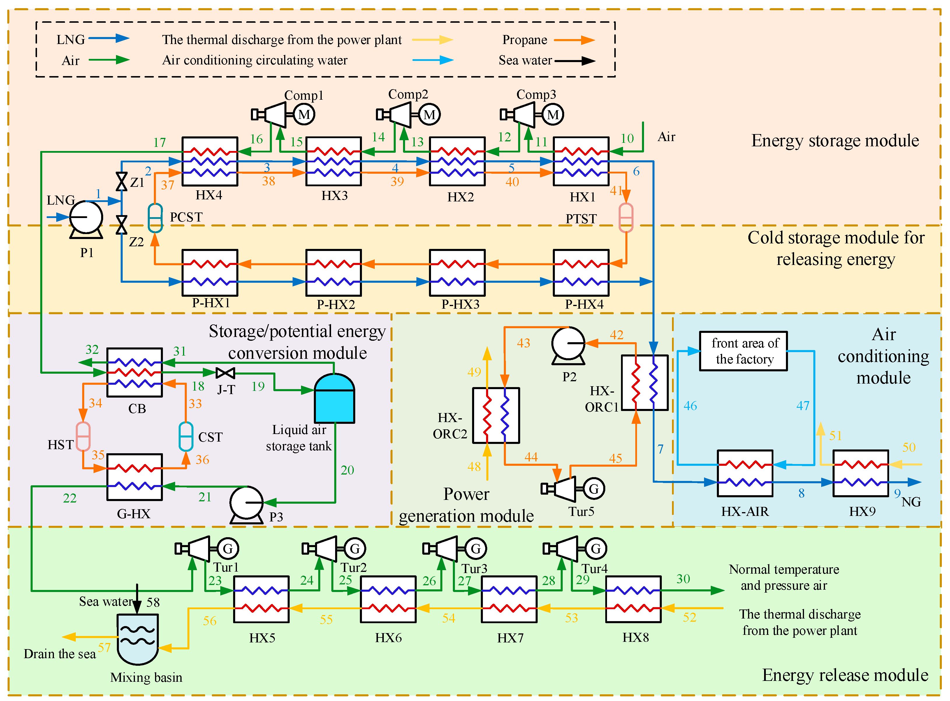
The LNG cold energy cascade utilization system comprises a liquid air energy storage system (LAES), a liquid air energy release system, a cold energy power generation system, and a cold energy air conditioning system. The system structure is illustrated in
Figure 1, with LNG serving as the cold source and the power plant’s warm wastewater, which contains residual heat, acting as the heat source. Prior to air storage, the air must be pretreated to remove moisture, carbon dioxide, and hydrocarbons to prevent freezing during the liquefaction process. The purified air serves as the feedstock for the liquefaction process [
26]. The system operates in two modes: energy storage and energy release.
The energy storage mode operates during off-peak electricity periods. First, atmospheric-pressure LNG is pressurized to 7500 kPa by pump P1. During the energy storage process, valve Z1 is open while Z2 is closed. Surplus electricity from the grid drives a three-stage air compressor, which pressurizes and cools ambient air through three stages of compression and inter-stage cooling. LNG and liquid propane from the cold storage device sequentially pass through four heat exchangers (HX4, HX3, HX2, HX1) to recover the compression heat generated by the air compressor. The warmed propane is stored in the propane thermal storage tank (PTST). The liquefied compressed air enters the cryogenic box for further cooling before being throttled through a J-T valve, facilitating liquefaction. The resulting liquid air is stored at atmospheric pressure and −192 °C. Any unliquefied cold air is returned to the cryogenic box to assist with cold storage. The low-temperature natural gas exiting heat exchanger HX1 enters the (ORC) of the cold energy power generation system. It exchanges heat with an intermediate medium, propane, in heat exchanger HX-ORC1. The liquefied propane is pressurized by pump P2 and vaporized by exchanging heat with the thermal discharge from the power plant in heat exchanger HX-ORC2. It then expands through turbine generator Tur5 to generate electricity, with the propane’s temperature and pressure restored before returning to heat exchanger HX-ORC1 to complete the cycle. The natural gas, now warmed by the power generation section, enters the cold energy air conditioning part, where it exchanges heat with the air conditioning loop water in the air conditioning heat exchanger (HX-AIR) to provide cooling. Finally, the low-temperature natural gas is heated to 1 °C via heat exchange with the thermal discharge from the power plant in heat exchanger HX9, after which it is transported externally.
The energy release mode operates during peak electricity periods. Valve Z2 is open while Z1 is closed. LNG is pressurized to 7500 kPa by pump P1 and then vaporized through the propane heat exchanger group (P-HX1 to P-HX4) in the cold storage device before entering the cold energy power generation section directly. The propane in the cold storage device is liquefied and stored in the propane cryogenic storage tank (PCST). Subsequently, the low-temperature natural gas is further warmed by the cold energy air conditioning system and finally heated to 1 °C by exchanging heat with the thermal discharge from the power plant in heat exchanger HX9 before being transported externally.
Simultaneously, liquid air exits the storage tank and is pressurized using low-temperature pump P3. The high-pressure liquid air is heated to near-ambient temperature via the vaporization heat exchanger G-HX. The high-pressure air then enters a four-stage expander, performing work to drive a generator and generate electricity, ultimately achieving peak shaving and valley filling.
During energy release and power generation, the liquid air storage tank activates its self-pressurizing device to maintain a stable internal pressure. To enhance energy efficiency, the gaseous cold air released from the storage tank during energy storage is recovered in the cryogenic box to aid cold storage. Selecting an efficient working fluid for intermediate energy storage depends on its isobaric heat capacity and operating temperature range. Propane is chosen for its high isobaric heat capacity and appropriate temperature range, with a melting point below −183 °C.
4. Results and Analysis
In this system, LNG sequentially undergoes heat exchange with air, the cold energy power generation ORC system, and the air conditioning loop water. After simulation using Aspen HYSYS V14, the key parameters of LNG (points 1–9) and air (points 10–30) in the system are shown in
Table 3 and
Table 4, respectively. The heat exchange curves of LNG are shown in
Figure 2 and
Figure 3. The total cold energy released by LNG when vaporized to 1 °C reaches 61,069.49 kW.
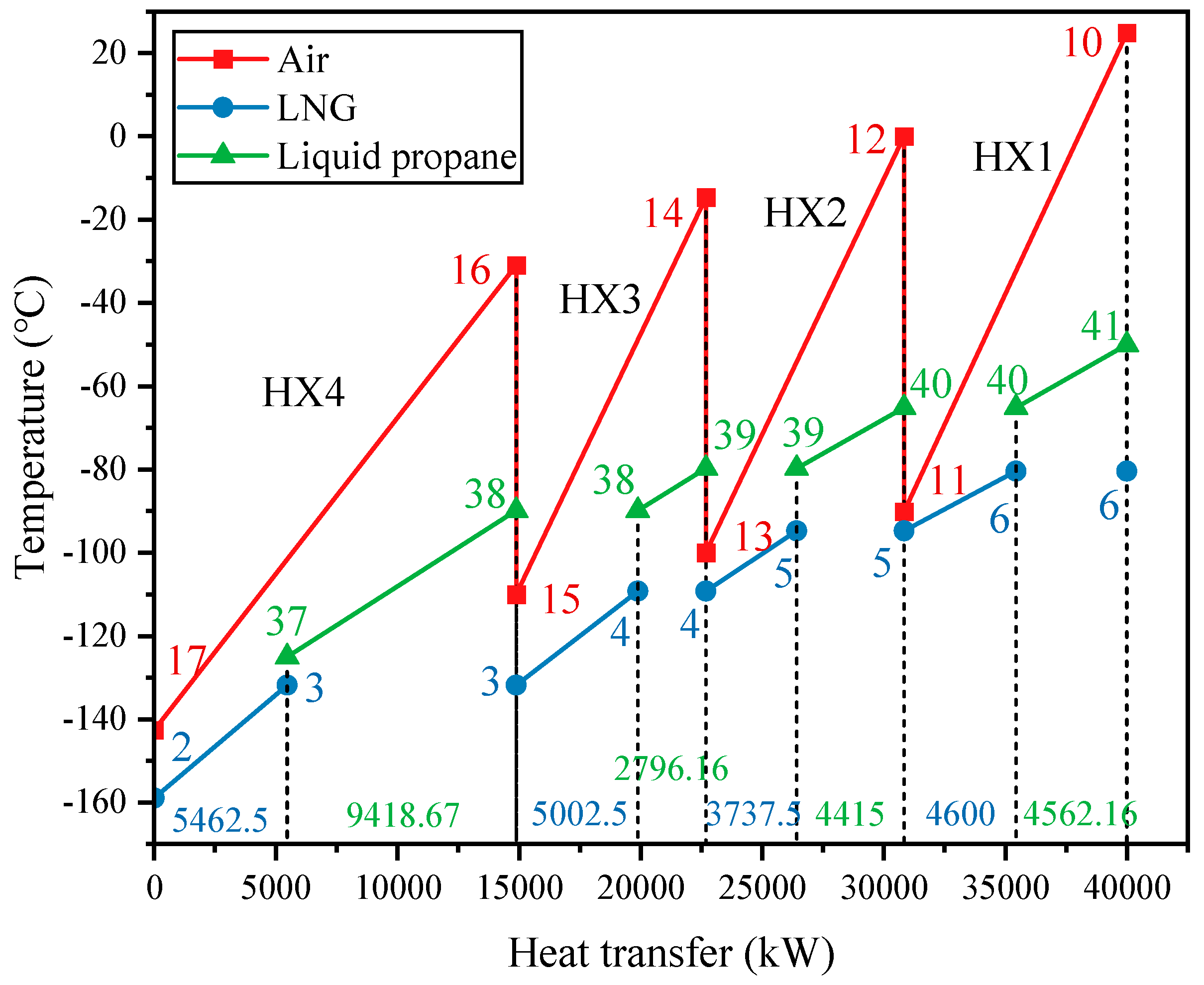
In the entire vaporization process of LNG, the cold energy released in the low temperature range (−162 °C to −80 °C) is the highest, reaching 18,802.5 kW, which accounts for approximately 44.37% of the total cold energy. As shown in
Figure 2, this portion of the cold energy is absorbed by the LAES system, with liquid propane (points 37–41) and LNG (points 2–6) jointly providing cold energy for air liquefaction. As air flows through HX1, LNG provides 4600 kW of cold energy and liquefied propane contributes 4562.16 kW, cooling the air to approximately −90 °C. Moving to HX2, LNG supplies 3737.5 kW and liquefied propane 4415 kW, reducing the air temperature to around −100 °C. In HX3, LNG provides 5002.5 kW and liquefied propane 2796.16 kW, cooling the air to approximately −110 °C. Finally, in HX4, LNG supplies 5462.5 kW and liquefied propane 9418.67 kW, lowering the air temperature to below −140 °C. Overall, the air absorbs 42,377.5 kW of cold energy from LNG and liquefied propane throughout the process.
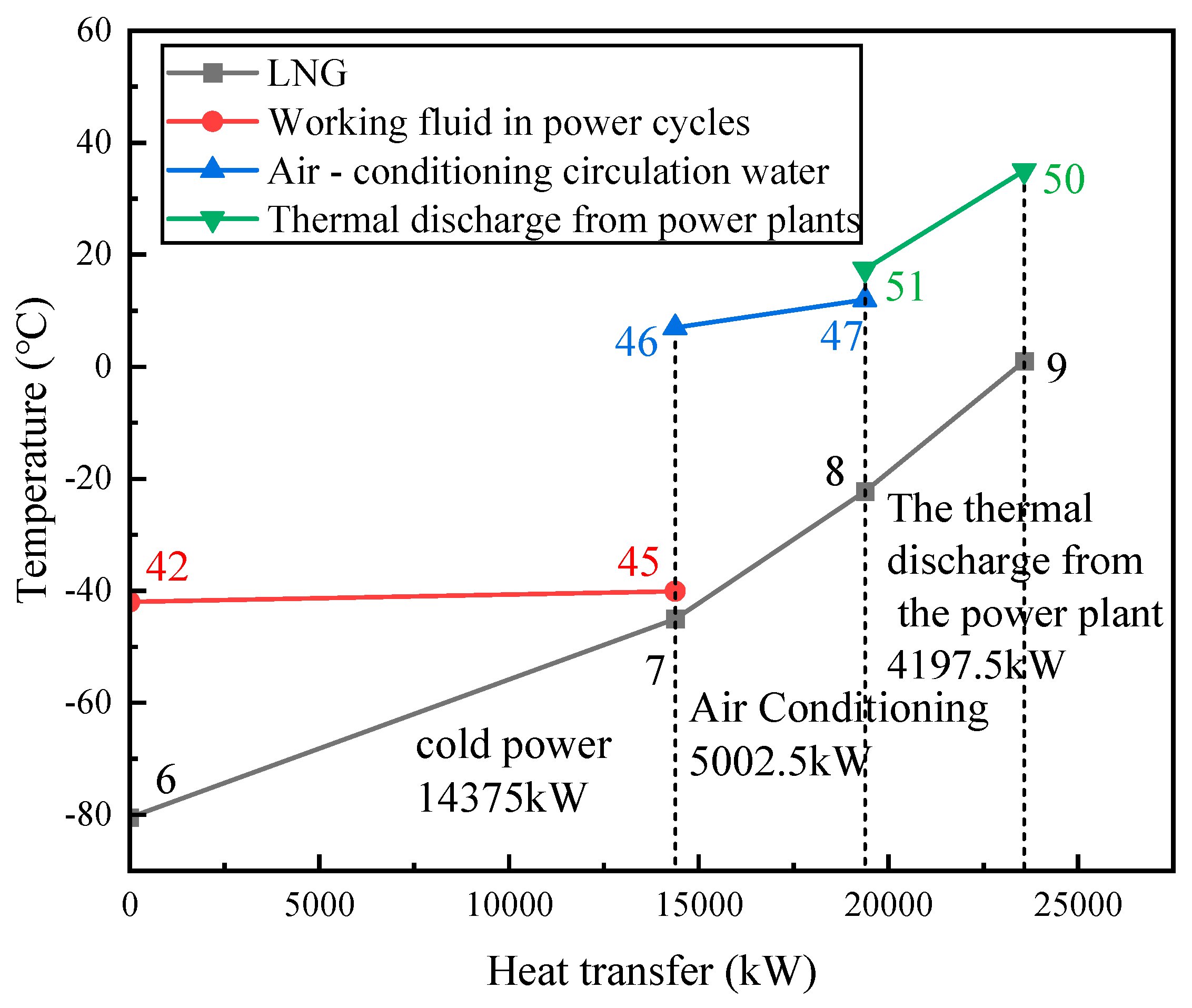
As depicted in
Figure 3, the ORC system harnesses 14375 kW of cold energy from the medium temperature range (−80 °C to −45 °C) of LNG, constituting 33.92% of the total cold energy. Within the ORC system, propane, once liquefied by LNG cooling, undergoes a temperature cycle via heat exchange with the thermal discharge from the power plant, leading to minimal temperature variation in the ORC system (points 42–45). The high temperature range (−45 °C to 1 °C) of LNG contains 9200 kW of cold energy, with the cold energy air conditioning system absorbing 5002.5 kW, approximately 11.8% of the total cold energy. Concurrently, the air conditioning circulating water is cooled from 12 °C to 7 °C. The remaining 4197.5 kW of cold energy is absorbed by the thermal discharge from the power plant, approximately 9.9% of the total cold energy. The natural gas is then transmitted to the pipeline upon meeting the external transmission requirements. Cascaded utilization of LNG cold energy enhances the energy utilization rate.
4.1. Cycle Efficiency Analysis
In conventional large-scale energy storage systems, cycling efficiency typically falls below 75%. However, when external energy is added to the system, cycling efficiency can exceed 100%. This increase in cycling efficiency directly boosts the net power output of the energy storage system, enhancing the economic returns of the project. After simulation, the system’s performance parameters for the pump, compressor, and expander are shown in
Table 5.
During the energy storage process, the power consumption of pumps P1, P2, and compressors Comp1, Comp2, and Comp3 totaled 20,780.99 kW, while the power generation of expander Tur5 amounted to 2820 kW, resulting in a net power consumption of 17,960.99 kW. In the energy release process, the power consumption of pumps P1, P2, and P3 totaled 2301.99 kW, while the combined power generation of expander units (Tur1, Tur2, Tur3, Tur4, and Tur5) reached 21,310 kW, resulting in a net power output of 19,008.01 kW. The cyclic efficiency of the new air–liquid energy storage system was 105.83%. Compared to conventional energy storage systems, this system not only receives surplus power from the grid but also utilizes LNG cooling for energy storage, resulting in a cycle efficiency greater than 100%.
4.2. Exergy Efficiency Analysis
4.2.1. Exergy Flow Analysis
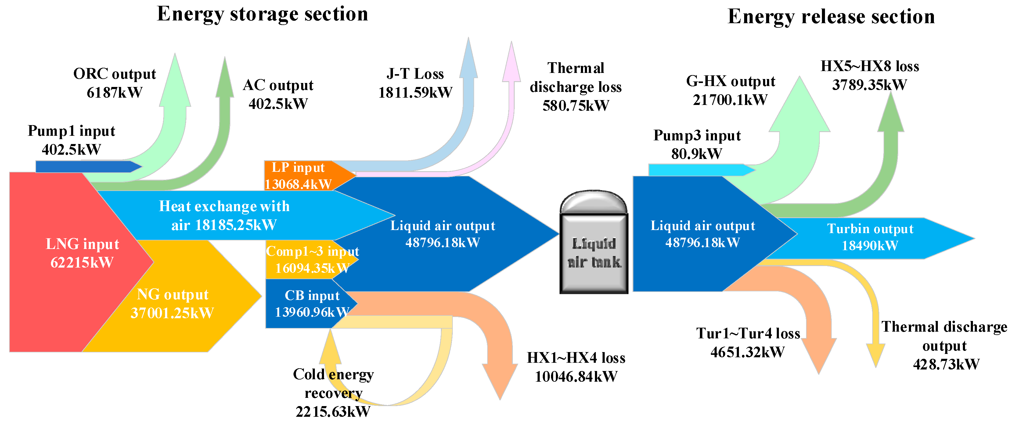
Figure 4 illustrates the exergy flow diagram of the LNG cold energy utilization process. During the energy storage process, LNG at −162 °C contains 62,215 kW of cold energy and P1 inputs 402.5 kW of effective energy to increase the LNG pressure to 7500 kPa. Then, 18,185.25 kW of cold energy is consumed in heat exchange with the air, 6187 kW is used by the cold energy generation system, and 402.5 kW is consumed by the air conditioning circulating water. The three-stage compressor inputs 16,094.45 kW of effective energy, while liquid propane (LP) contributes 13,068.4 kW, and the cold box (CB) inputs 16,176.59 kW, including 2215.63 kW from the un-liquefied air return. The J-T process consumes 1811.59 kW, and the heat exchange with the thermal discharge from the power plant requires 580.75 kW. The heat exchangers HX1 to HX4 consume 10,046.84 kW, while the air conditioning circulating water consumes 402.5 kW. The cold energy consumed by heat exchangers HX1 to HX4 totals 10,046.84 kW, with the final output of liquid air having a cold energy value of 48,796.18 kW. The NG cold energy value for 1 °C output from the system is 37,001.25 kW. During the energy release process, LNG continuously gasifies to release cold energy. The high-grade cold energy used to liquefy the air during storage is now recovered by propane, while the remaining LNG cold energy follows the same utilization process as in the storage mode. Liquid air exits the storage tank, is pressurized by P3 with an input of 80.9 kW of effective energy, and then undergoes gasification in the gasification heat exchanger, consuming 21,700.1 kW of cold energy. The heat exchange between the air and the thermal discharge from the power plant consumes 428.73 kW, while heat exchangers HX5 to HX8 account for a loss of 3789.35 kW, and turbines Tur1 to Tur4 consume 4651.32 kW for electricity generation. Finally, the turbine generates a total of 18,490 kW of electricity.
4.2.2. Exergy Destruction Analysis
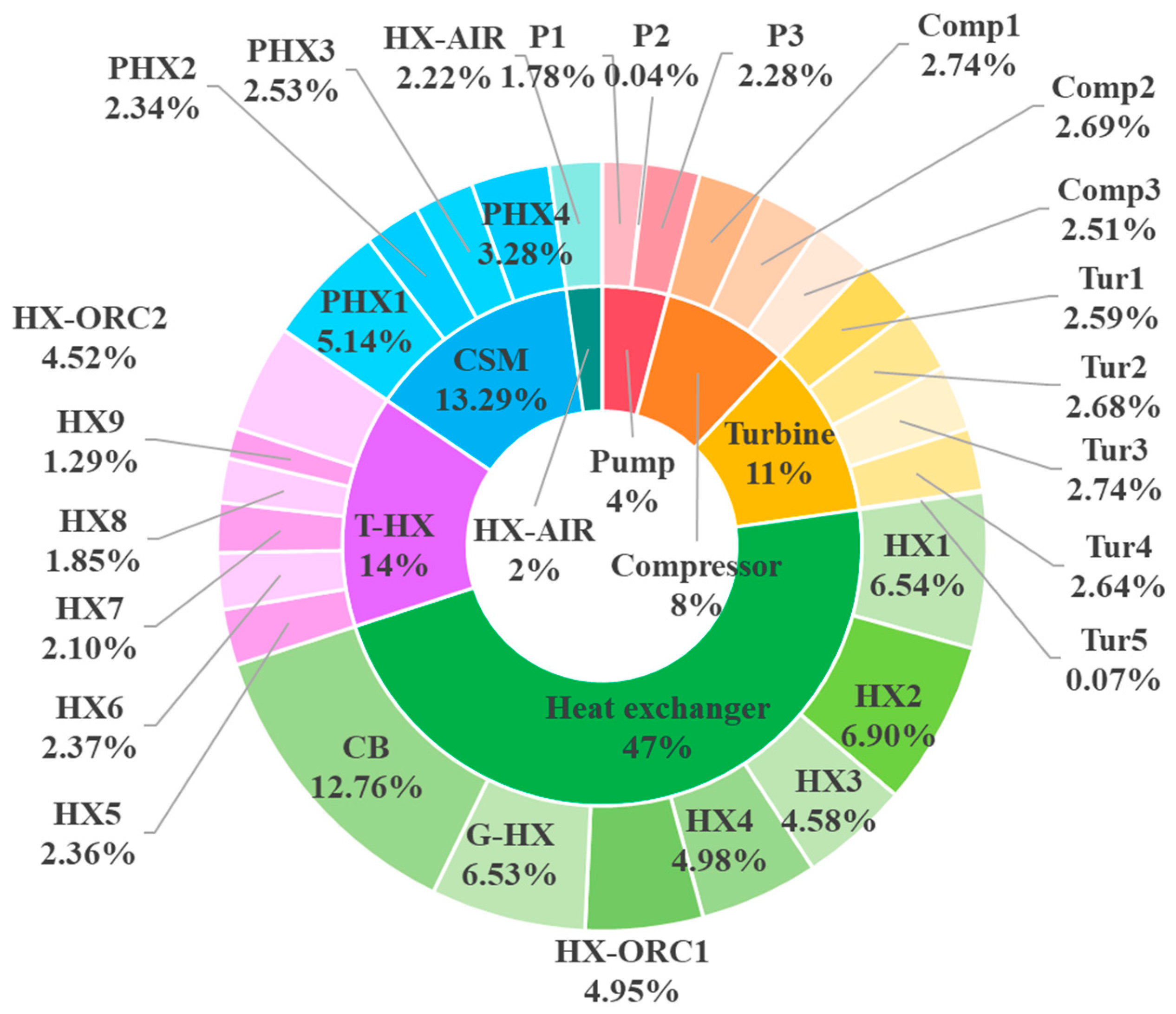
The total system exergy loss is 43,669.24 kW. The exergy loss percentage for each equipment in the system is shown in
Figure 5. The largest exergy loss occurs in the heat exchangers (including five multi-strand logistics heat exchangers, the cold box, and the gasification heat exchanger), which account for about 47% of the total loss. This is due to the temperature difference during heat transfer between the LNG and the air or medium, resulting in significant effective energy loss. The next largest loss, about 15%, occurs in the thermal discharge from the power plant heat exchanger, where cold energy released by the low-temperature working mass is carried away by the thermal discharge resulting in effective energy loss. During the energy release process, the heat exchanger in the cold storage unit causes effective energy loss during heat exchange between LNG and propane, accounting for about 13.29%. The three air compressors input a total of 33,271.29 kW of effective energy. However, due to interstage cooling by LNG, the energy consumption and exergy loss of the compressors are reduced, resulting in an exergy loss of only 3465.65 kW, or 8%, with each compressor achieving an exergy efficiency of over 80%. The temperature difference between LNG and the air conditioning circulating water causes an exergy loss of 969.70 kW, or about 2%.
The exergy destruction of the pumps, compressors, and expanders is presented in
Table 6. The total input effective energy of the system, including LNG coolant and the energy input to the pumps and compressors, is 47,075.74 kW. The output effective energy consists of the expansion work from the liquid air energy-releasing power generation system, the ORC expansion work, and the electricity used to refrigerate the air conditioning circulating water, totaling 26,310 kW. Thus, the total energy efficiency of the system is 55.89%. This represents an improvement of about 6.18% over the conventional liquid air energy storage system.
4.3. Economic Analysis
Net Present Value (NPV) Analysis
The capital cost includes equipment procurement cost and installation cost. According to the economic analysis module of Aspen HYSYS software V14, the capital costs of each equipment in the system design phase are shown in
Table 7, with a total of CNY 156,854,600. According to the electricity price policy for industrial users at an LNG receiving station in Tangshan, Hebei, different electricity prices are applied at different times of the day, with peak electricity price at 0.8473 CNY/kWh and valley electricity price at 0.1233 CNY/kWh.
Due to the use of propane tanks as intermediate storage, the system has flexible energy storage and release capabilities, which can flexibly generate electricity according to users’ electricity demands. The cold energy power generation system operates along with the vaporization of LNG. During the energy storage period, the ORC system can provide partial electrical energy for the three compressors. During the energy release period, the ORC system and the liquid air energy release system generate electricity together. The cooling capacity provided by the cold energy air conditioning can save 5000 kW of electrical energy, which can also be considered as part of the project’s revenue.
The plant’s service life is calculated as 25 years, with a discount rate of 7%, a tax rate of 25%, a daily working time of the system of 22 h, a daily peak electricity time of 11 h, and a daily off-peak electricity time of 11 h. The air conditioning working time is calculated as 90 days per year, with 22 h of work each day.
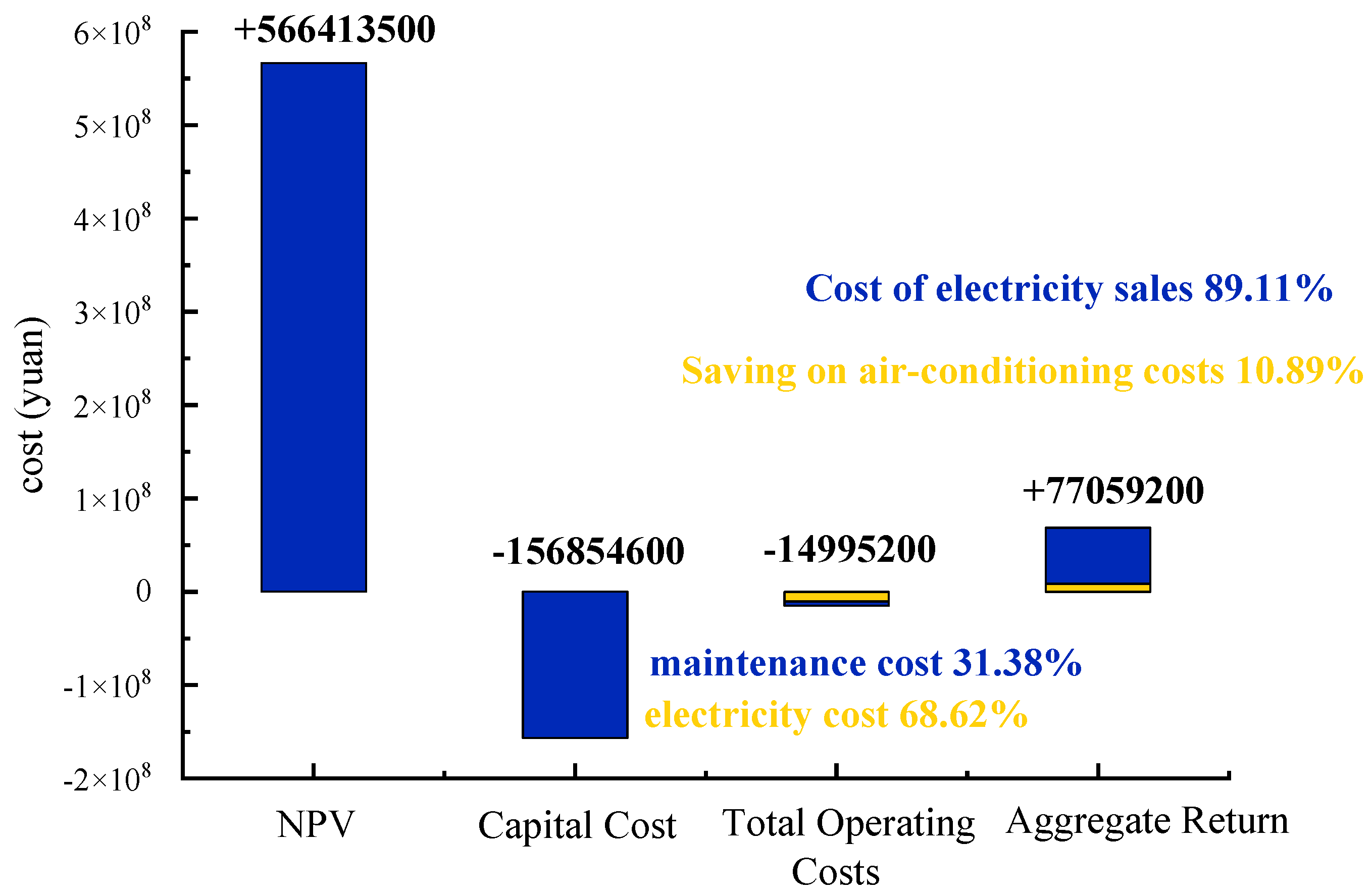
As shown in
Figure 6, when conducting an economic analysis of this project using the net present value method, the net present value is calculated to be CNY 566,413,500, and the project can recover its initial investment cost within 2.53 years. The annual operating cost of the project is CNY 149,952,000, of which the electricity consumption cost is CNY 102,896,000 and the maintenance cost is CNY 47,056,000. The total revenue of the project is CNY 770,592,000, which includes two parts: one is the CNY 686,710,000 obtained from selling electricity during peak electricity periods, and the other is the CNY 83,883,000 saved from air conditioning electricity costs.


