1. Introduction
Small-scale energy sources are highly anticipated, and a heat engine is a promising candidate due to its high power and high energy densities compared to other energy sources, such as batteries. The smallest gas turbine engines for commercial products have an output of about 2–3 kilowatts, as shown by Kumakura et al., 2004 [
1], and smaller ones were presented as prototypes in the research of Nagashima et al. [
2] and Isomura [
3]. A more challenging source is the power micro-electro mechanical systems (MEMS) gas turbine suggested by the MIT group. The MIT micro-engine (1997 [
4,
5,
6] and 2000 [
7]), a program to develop a micro-gas turbine engine capable of producing 10–50 W of electrical power in a package less than one cubic centimeter in volume, was an attempt to transfer the advantages of macro-scale engines to a more portable scale, using MEMS technology to build a family of micro-scale devices such as gas turbine engines, jet turbines, and electric turbines. The advent of MIT’s MEMS turbine project in 1995 was based on the theoretically expected increase in power density (power/mass = 1/L) after reducing the linear dimensions of the device. However, these measures encountered unexpected problems. It turned out that the solutions developed over the past half century for large mechanical devices are not necessarily applicable at the micro-scale. The main challenges were related to the manufacturing of complex micro-turbo-machinery components that maintain the necessary combustion pressures and temperatures, their high speeds, and the requirement that they are machined to micron tolerances.
Sometimes, these small gas turbines are called ultra-micro-gas turbines (UMGTs); these are smaller than conventional micro-gas turbines, although their output power has a wider range; that is, it is measured in kilowatts or decawatts. Therefore, the issues facing them are different.
Kilowatt UMGTs can be operated independently, but their thermal efficiency is very low due to the lower pressure ratio and the lower turbine inlet temperature in the thermo-cycle. The lower pressure ratio is obtained because a centrifugal compressor is generally used for air compression, so the multistage structure is hard to introduce. The lower turbine inlet temperature is because the film-cooling technique is not available to the turbine because the blade is too thin. For these reasons, a heat exchanger is generally used to improve the thermal efficiency, but this has a much larger volume than the turbo-machinery, so the advantages of higher power and increased energy densities are mitigated.
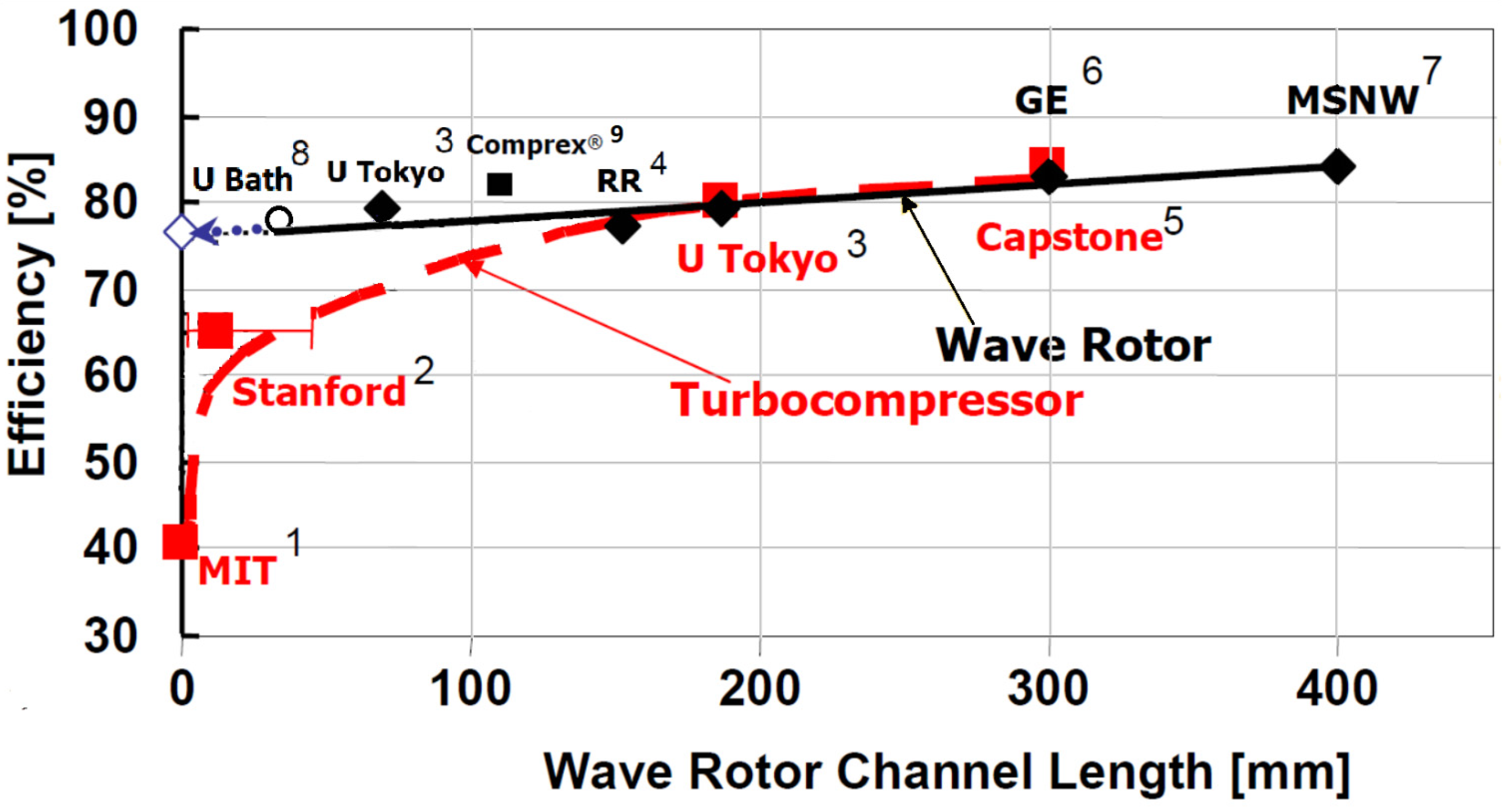
In the case of a decawatt UMGT (power MEMS), the issues are more serious. One major issue is the high rotor speed. The rotor diameter is less than 10 mm, so more than 1,000,000 rpm rotational speed is necessary to maintain the conventional peripheral speed of the rotor. Even when such a high rotor speed is achieved, the component efficiency drops with a decrease in rotor diameter, as shown in
Figure 1.
In the paper of Dean et al., 2008 [
8], some experimental data were collected and, based on these data, turbine and compressor efficiency predictions were made at rotor sizes corresponding to the MEMS range. The scaling and predictions are based on the results obtained by Gerendas et al., 2000 [
9], with relatively large rotor dimensions (74 mm). The measured turbine and compressor efficiencies are shown in
Figure 1 by white circles. The data were scaled to lower and higher rotor dimensions.
Figure 1 also shows other estimates based on the scaling principle presented by Dixon 1998 [
10] and based on the experimental data presented in the work of Dean et al., 2008 [
8], for two parameter τ values equal to 3 and 4, representing the ratio of absolute gas temperatures at the inlet to the turbine and compressor. Based on the dimensions of the turbine and compressor described in the work of Epstain 2004 [
11], their estimated efficiencies are shown. The forecast developed by Sirakow 2005 [
12] is visualized, as well as the deviating predictions obtained by Peirs et al., 2003 [
13], and Peirs et al., 2004 [
14]. The chart shows the limits of the applicability of the Brayton cycle devices at the estimated efficiency of 0.50, and the possible viscous turbine
efficiency below this limit.
Another issue is the increased heat transfer. A major and long-unrecognized problem in very small-scale thermal devices is the occurrence of very large temperature gradients and, as a result, large heat flows between the components of the device. While the mechanical power-generating parts (turbines) are designed to operate at high temperatures, the gas-compression parts suffer a significant drop in efficiency when operating at higher temperatures. The main, and thus far unsolved, problem is the need to obtain thermal separation between the compressor and turbine.
A summary of research on a classical micro-turbo-engine made using MEMS technology can be found in the article by Epstein, 2004 [
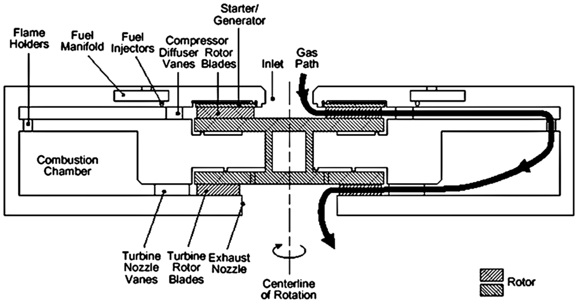
11]. The basic components of the engine shown in
Figure 2, such as the radial compressor, radial turbine, gas bearing system, combustion chamber, and electric generator, were designed and fabricated in silicon wafers. Although the individual components worked, once integrated, due to the strong heat transfer between the turbine and compressor, the compressor’s performance was not sufficient to achieve a sufficient compression ratio for the turbine to generate external power. In the considered engine design, the turbine rotor was conductively cooled through the compressor disk to the compressor air, which had a quite deleterious effect on the cycle performance, and thus on the net engine output. Improving this performance requires thermally isolating the turbine from the compressor, which can be accomplished by hollowing the shaft between them ~100–200 micro-meters along the turbine disk. When this is achieved, the temperature capacity of the turbine rotor must be increased.
The influence of heat transfer is investigated in more detail in the work of Nagashima et al., 2005 [
2]. In this investigation, the influence of temperature changes due to heat transfer is separated from the polytropic efficiency of the compressor or turbine in order to consider the heat transfer influence more precisely. The results show the heat transfer between the engine components and the surroundings; the thermal efficiency is about 3%. This efficiency is very low, but it is supposed that a UMGT with such low efficiency is still attractive because it can achieve higher power and energy densities compared to a battery.
Regarding the tests of each component, a few tests on a micro-combustor can be found in the works of Mehra et al., 2000 [
15], Waitz et al., 1998 [
16], Spadaccini et al., 2002 [
17], Sakurai et al., 2013 [
18], and Mehra et al., 2000 [
15], who present the design, fabrication, packaging, and experimental test results for a six-wafer combustion system for a silicon micro-engine. The 0.195 cm
3 combustion chamber is shown to sustain a stable hydrogen flame over a range of operating mass flows and fuel–air mixture ratios and to produce exit gas temperatures exceeding 1600 K. It also serves as the first experimental demonstration of stable hydrocarbon micro-combustion within the structural constraints of silicon. Combined with longevity tests at elevated temperatures for over ten hours, these results demonstrate the viability of a silicon-based combustion system for micro-heat engine applications. The walls were expected to operate at temperatures of approximately 1000 K.
On the other hand, compressor and turbine tests seem to present unsolved problems. Notably, it appears to be very difficult for a compressor to achieve the necessary compression ratio, as shown in the research of Nagashima et al., 2005 [
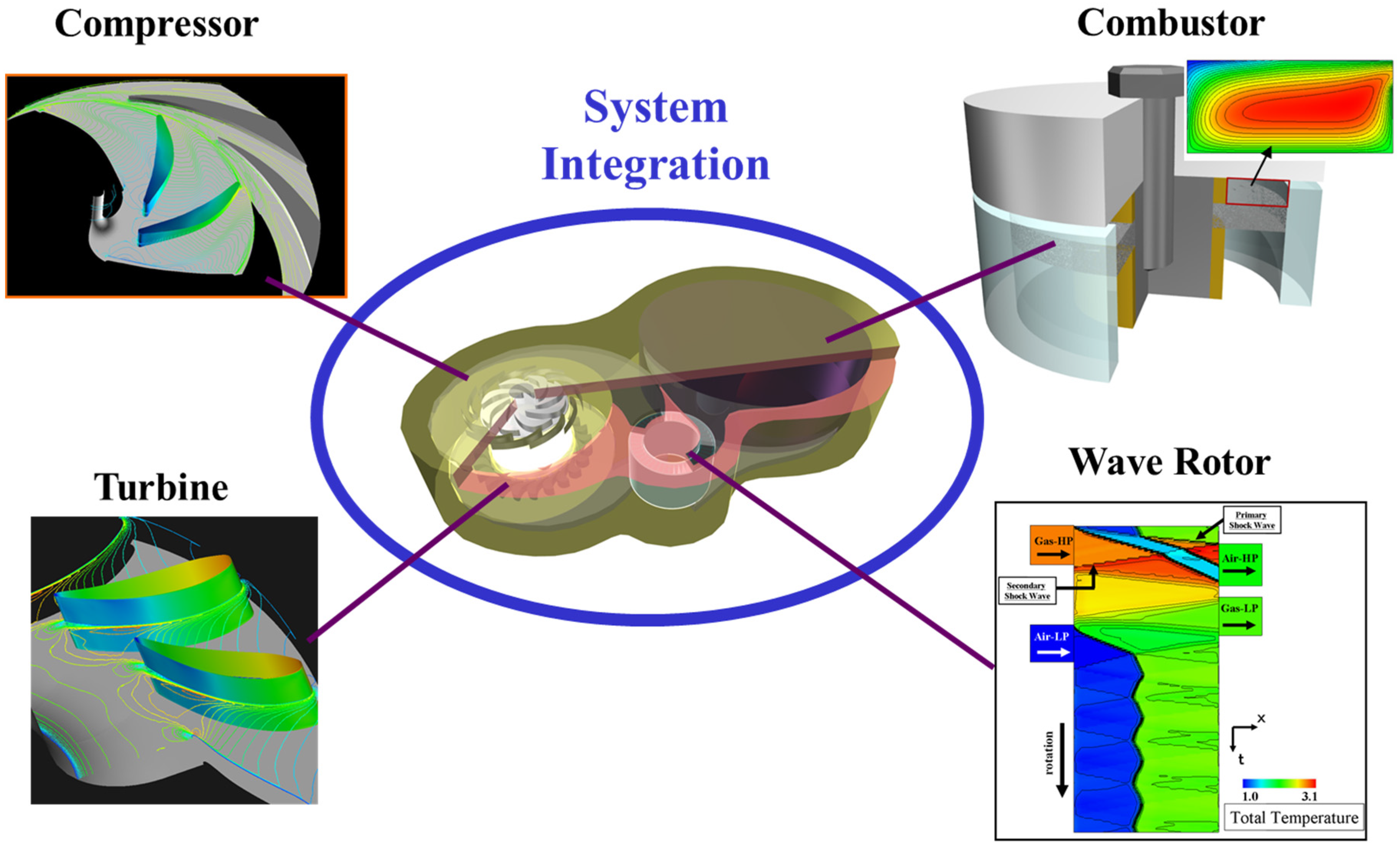
2]. Therefore, it would be effective to adopt compressor and turbine devices with a different working principle, and a wave rotor is one potential candidate. A wave rotor is a machine that exchanges energy between air and gas using unsteady pressure wave propagations in rotating tubes, enabling state changes across varying shock wave thicknesses. Machines with unsteady compression have three main features: self-cooling capabilities, lower speeds, and less sensitivity to downsizing. When applied to MEMS technology, they can improve typical designs based on steady-state flows. In this paper, the research on wave rotors and other unsteady compression devices is introduced, focusing on small heat engine systems (see
Figure 2).
This review paper presents the results of a number of works related to the use of wave rotors in the construction of micro-heat engines. Against the background of the presented problems regarding small-dimensional engines with a classical stationary flow system, alternative devices using unsteady processes are presented. A rather long series of studies in which attempts were made to use unsteady processes for the simultaneous compression and expansion of the medium are presented. A number of works that proved to be only partially successful are also shown. Successive steps to learn about the favorable and unfavorable features of wave processes are shown. The design of an engine using the favorable features of the transient compression process, where the inertia of the medium is used to increase the pressure, is presented. It is shown that in the transient expansion process, the inertia of the medium is not always beneficial. It helps to clean the rotor channels and fill them with the new refrigerant, but is not suitable for efficient torque generation. A solution in the form of a hybrid system that uses an unsteady process for compression and a steady-state process to expand the compression and generate a useful torque is shown. The possibility of using new environmentally friendly energy carriers comprising hydrogen peroxide and hydrogen to generate torque in a safe way during decomposition and fixed-volume combustion is presented, which is associated with a potential increase in the thermodynamic efficiencies of these processes.
2. Wave Rotor
Upon hearing the word “wave rotor”, the first thing that comes to mind is the Comprex
® turbocharger, Gyarmathy 1983 [
19], Berchtold 1959 [
20] and 1985 [
21], which has a proven track record in diesel engines. However, its application to high-power heat engines such as aviation engines was unsuccessful, since it did not meet the goal of being lightweight with a high thermal efficiency. So, what about the extremely small heat engines presented in the current discussion?
In this section, we touch on installation challenges and the introduction of several different types of wave rotors in such micro-engine systems. Previous examples, including the practical Comprex
®, are described in detail in a review paper by Akbari et al., 2006 [
22]. It will be also of interest here to refer to the analytical and computational methods used to investigate the wave dynamics observed in wave rotors or pressure exchangers; a variety of computational techniques, including the classical method of characteristics and modern numerical schemes, have been developed over a long period of time [
23,
24,
25,
26,
27,
28,
29,
30,
31,
32,
33,
34,
35,
36,
37,
38,
39,
40,
41,
42,
43,
44,
45,
46,
47,
48,
49].
2.1. Internal Flow Dynamics and Downsizing Influence
With the existing and well-known problems in classical thermal micro-engine design, solutions based on the implementation of unsteady flows to realize compression processes appear to be an interesting alternative. However, the design of micro-scale flow devices requires consideration of the specific problems associated with the movement of pressure waves in channels with very small dimensions.
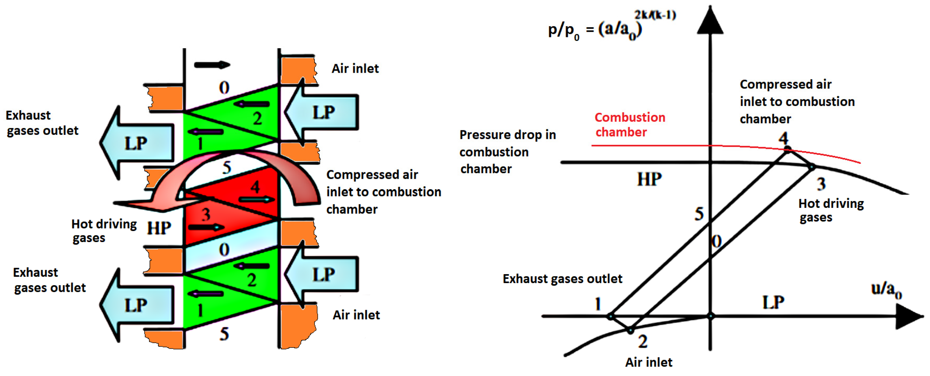
Figure 3 shows a schematic view of a wave rotor. As seen in this figure, a wave rotor comprises a rotor with straight channels and four ports for charging and discharging air and combustion gas.
Figure 4 shows a wave diagram that shows the propagating pressure waves and charging/discharging gases in the rotating tubes using characteristic lines. As shown in this figure, low-pressure air is compressed by shock waves propagating in the tubes, so the compression ratio does not directly depend on the rotating speed but on the shock wave strength. There are two different types of rotor in the wave diagram: through-flow and reverse-flow types. In the through-flow type, air and combustion gas alternately blow through the tubes; therefore this type has a self-cooling feature, which should make it suitable for topping gas turbines. In the reverse-flow type, air and gas are charged and discharged on each side; therefore, the temperature distribution is uneven, reducing the self-cooling feature but offering an advantage in terms of compression ratio. This was adopted in Comprex
®, which is the only practical supercharger product. In any type, since the internal flow dynamics are inherently unsteady, the influence of downsizing would be different from that in conventional turbo-machineries.
The basis for the research on the use of wave rotors at the micro-scale was the work of Brouillette, 2003 [
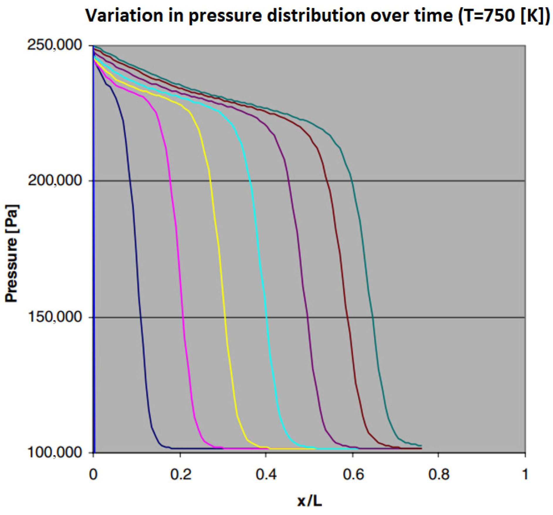
50], indicating the potential of using shock waves to implement the air-compression process in such devices. The work includes the presentation of a computational model that takes into account the movement of waves at a small scale. The paper points out that there are some differences in the propagation of waves at the micro-scale compared to their typical use at the macro-scale. In the paper, a model of the effect of scale, obtained through molecular diffusion phenomena, on the generation and propagation of shock waves is proposed. A simple parameterization of the resulting shear stress and heat flux on the wall leads to the determination of new jump conditions, which show that, for a given Mach number of the wave at small scales, the resulting particle velocities are lower, but the pressures are higher. In addition, the model predicts that the small-scale flow should be isothermal and that the minimum wave velocity, determined through viscous effects, is subsonic. Experiments with a miniature shock tube (5 mm diameter cross-section) using low pressures to simulate small-scale effects have shown qualitative agreement with the proposed model.
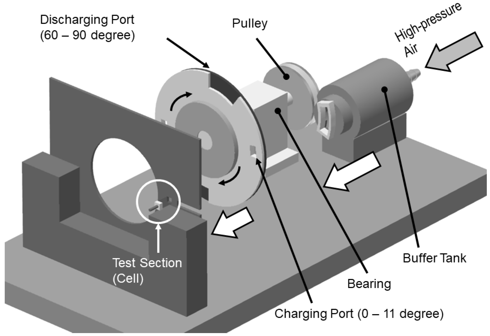
Another investigation is found in the work of Okamoto and Araki, 2008 [
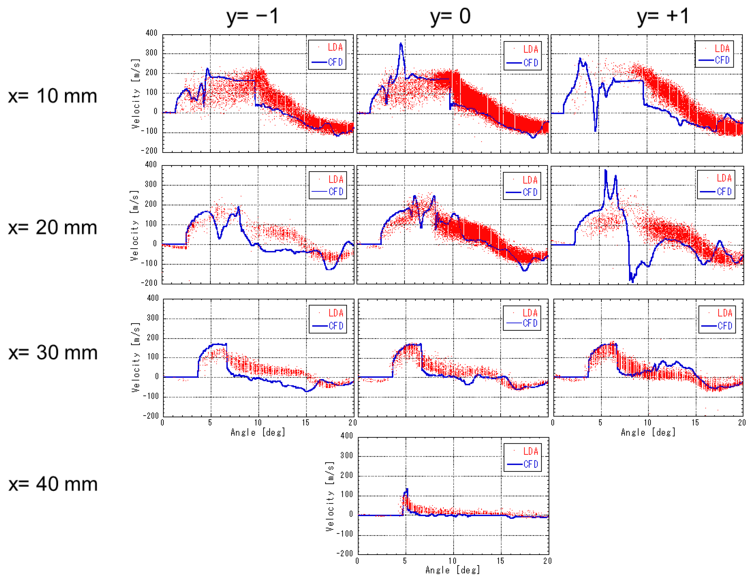
51]. In these studies, a flow structure similar to that of a wave rotor was generated in small tubes (3 × 3 mm cross-section), and the shock wave propagation process was discussed. Experiments were carried out using a test rig, in which a small tube was fixed and ports were rotating (
Figure 5). Laser Doppler Anemometer (LDA) measurements and shock wave visualization using the Schlieren method were carried out and the influence of the tube lengths that yielded different wall friction losses in the design of micro-wave rotors was discussed. The results showed that the pressure increase and flow acceleration caused by the shock wave propagation are not strongly affected by miniaturization, as long as the non-dimensional design parameter values are kept within a conventional range (
Figure 6). However, when the tube length is much longer than that, the propagation velocity of the shock waves and flow velocity is affected, even though a longer tube allows for a slower rotation speed during operation.
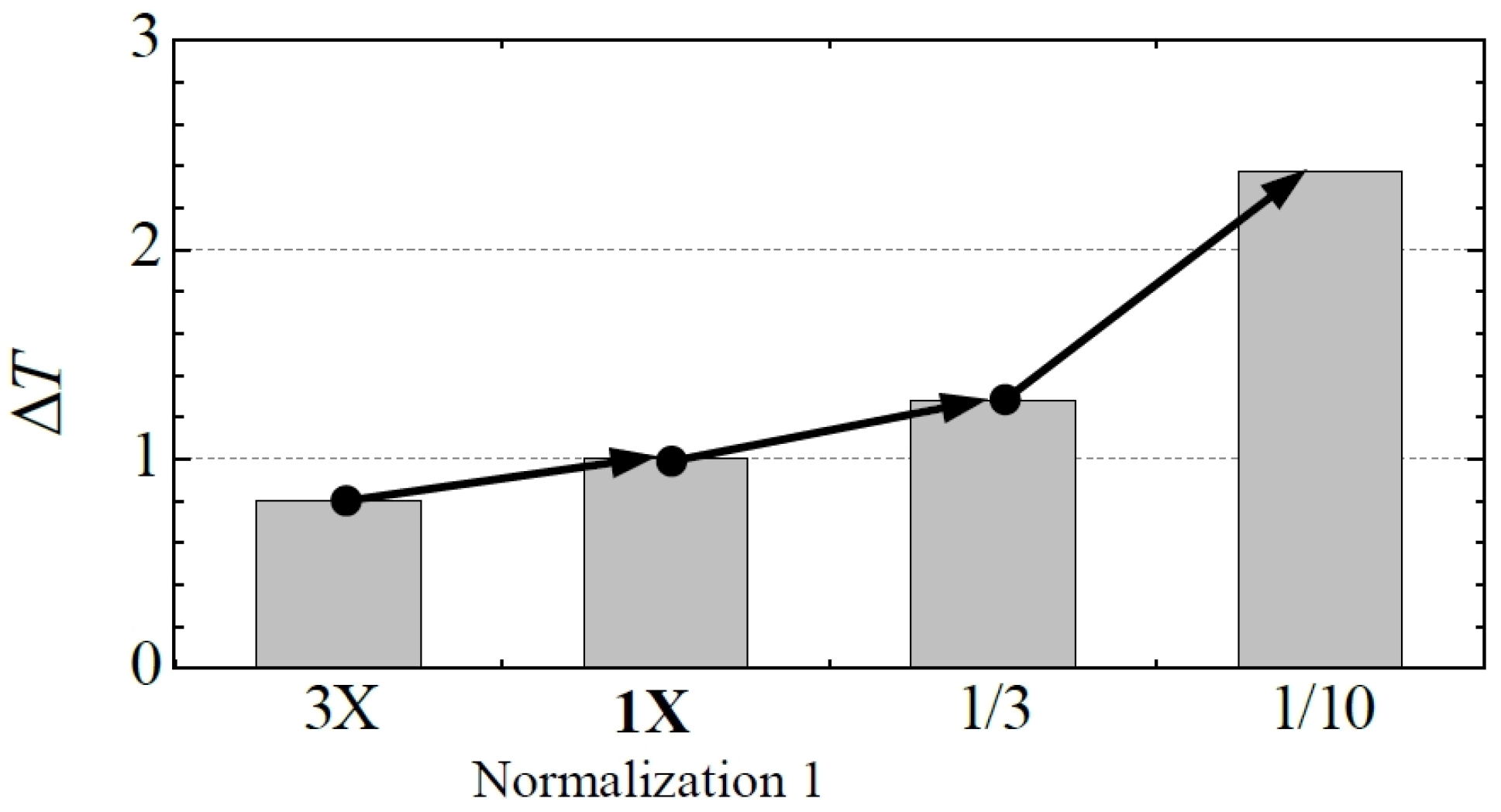
Another concern is the influence of heat transfer. In general, the influence of heat transfer becomes more serious in smaller turbo-machines due to its higher Biot number, but its influence in wave rotors is not clear because its internal flow dynamics are fully unsteady. To clarify the influence of heat transfer on the wave rotor’s internal flow dynamics, a 3D numerical simulation with conjugated heat transfer treatment was carried out in the work of Deng et al., 2015 [
52], to investigate the influence of heat loss in wave rotors of different sizes by comparing the results with those obtained under isothermal and adiabatic wall conditions. The results show that the influence of heat transfer is negligible in a wave rotor designed for kilowatt UMGT, but not one designed for decawatt UMGT. The influence of heat transfer can principally be seen as an increase in the temperature of the fresh air during its charging process, which weakens the shock waves and affects the subsequent exhaust process (
Figure 7). A higher heat flux appears behind the propagating shock waves, but its influence is not strong because its area is small.
From the studies presented above, it can be concluded that the influence of miniaturization is strong for the decawatt-size wave rotor due to its high heat transfer, while its influence is small for the kilowatt-size wave rotor (
Figure 8).
2.2. Cambered Channels
The paper by Tüchler and Copeland, 2019 [
53], details an extensive experimental investigation of a novel through-flow micro-wave rotor with symmetrically cambered passage profiles, designed for shaft power output as well as pressure exchange. The wave rotor is a four-port, three-cycle unit of 60 mm in diameter and 30 mm in length, which houses 46 channels. The unit was experimentally tested on a gas stand in open-loop configuration using electrical heaters as the source of heat for the high-pressure inlet and pressurized air for both inlet ducts.
A system was tested in which there were two sources of compressed air: hot air with higher-pressure HPG and air of a lower pressure and temperature. The two sources delivered different mass flows. The lambda parameter represents the ratios of mass flow rate from the higher-pressure HPG source to that generated by the lower-pressure LPA source. This parameter was obtained in the range of 1.7–3.2. On the outlet side, there were two pressure levels of HPA and LPG. Due to the different expenditures of the two flow loops, the phenomena of exhaust gas recirculation (EGR) and fresh air exhaustion (FAE) were observed (Wilson et al., 2007 [
54], Pohorelsky et al., 2005 [
55], and Chan et al., 2016 [
56]).
Throughout testing, the mass flow rates among the high-pressure inlets and outlets were balanced. A series of tests were conducted investigating the effect of variations in the rotational speed, ratio of inlet mass flow rates (loop flow ratio), axial clearances, and peak inlet temperature on wave rotor performance. The results show the importance of minimum axial clearance for maximum energy transfer, as well as to reduce the mixing of hot and cold flows. The competing relationship between pressure ratio, high-pressure-zone pressure differences, internal exhaust gas recirculation, and fresh air exhaustion is also highlighted. A peak shaft power of 450 W and a peak pressure ratio of approximately 1.63 were obtained.
The presented results of the experiments are especially useful for wave disk mixer applications (
Figure 9). The ratio of flow rates, which is much higher than 1, means they are not useful for supercharger and disk engine applications.
2.3. Radial Channels/Wave Disk
Numerous devices use an axial flow configuration, leading to heavy and bulky designs. Akbari et al., 2024 [
57], present an analysis of radial flow devices that could provide an alternative. Among other things, their paper presents examples of radial or disk-shaped wave rotor solutions, offering a reduction in axial length and more compact systems. The paper examines the historical and contemporary applications of disk-shaped machines, highlighting their benefits, limitations, and future prospects. The presented examples argue for the broader use of this unconventional geometry in existing and future power systems.
The following unsteady flow machines were presented: a disk-rotating detonation engine, a wave disk engine for automobile engines, a wave disk engine for power generation, a radial gas wave ejector, and a radial wave rotor refrigerator.
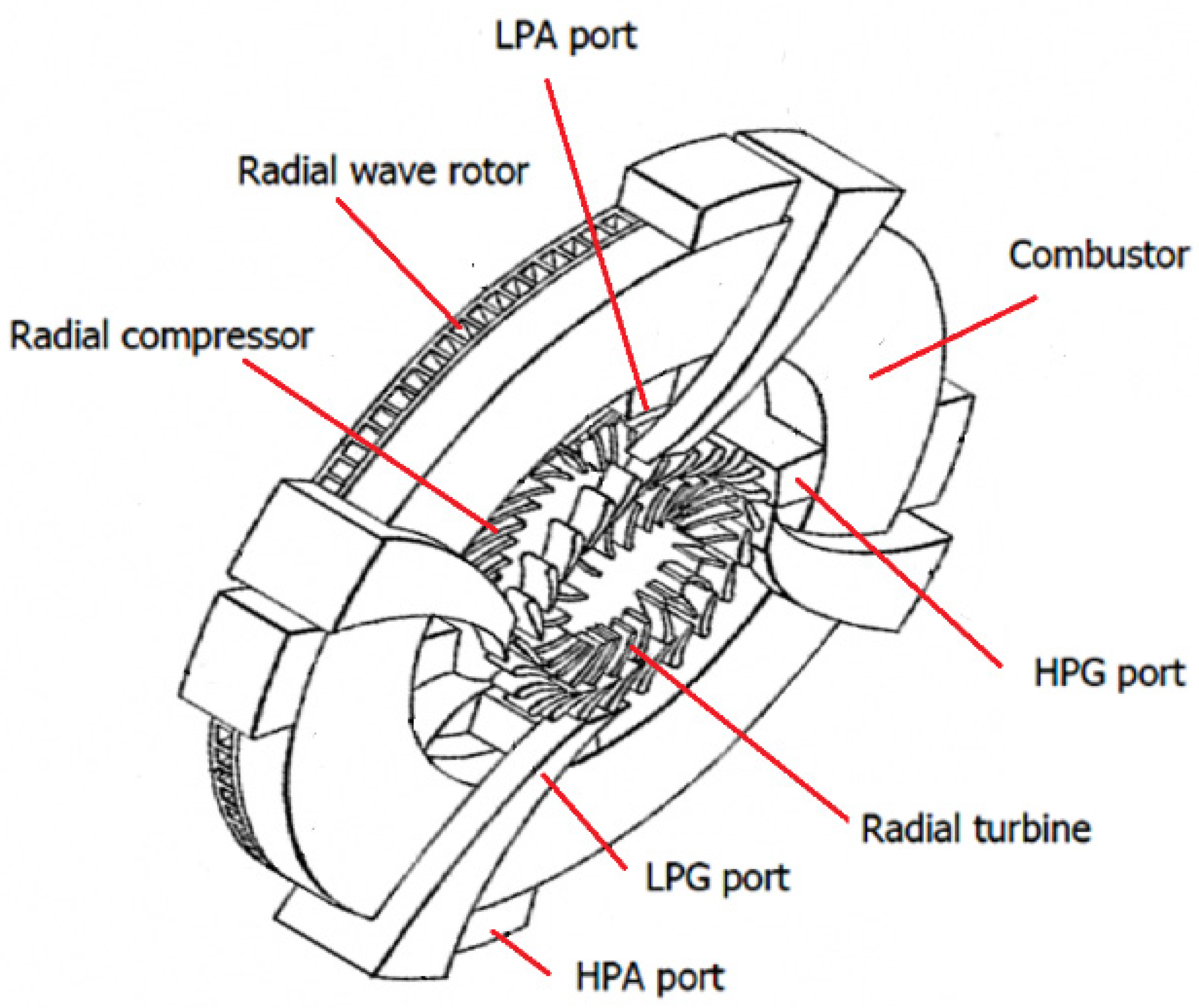
Regarding the MIT power MEMS turbine, the paper by Nagashima et al., 2005 [
2], present a radial wave rotor as a new wave rotor that can be fabricated using MEMS technology, along with some discussion of the technical issues (
Figure 10). The paper points out the benefits of using centrifugal forces to scavenge a radial rotor. The need to scavenge the channels of a wave rotor from exhaust gas and fill them with fresh air is an important problem in wave devices.
2.4. Micro-Combustor and Fuels
The combustor is an important component of the heat cycle engine and a major factor in determining the engine size. In conventional macro-sized gas turbines, combustors were developed to meet the requirements of high efficiency, low pressure loss, heat resistance, and a low environmental impact regarding the use of fossil fuels such as methane, propane, and jet fuels. To achieve the ultimate miniaturization, several factors that have a significant effect on the entire combustion field (quenching distance, characteristic time of diffusion velocity, heat loss to the wall, laminarization of the flow field) must be addressed, as discussed in the work of Nagashima et al., 2005 [
2]. For the MIT power MEMS gas turbine, Mehra et al., 2000 [
15], presented the design, fabrication, packaging, and experimental test results of a six-wafer combustion system for silicon engines, carrying out an elemental testing of the micro-combustor. The fuel used was hydrogen, which has the following characteristics compared to fossil fuels: (1) high calorific value, (2) wide flammable range, (3) burning speed one order of magnitude higher, (4) small ignition energy and quenching distance, (5) fast diffusion speed, and (6) little flame radiation. Apart from the issue of fuel tank volume, it can be said to be optimal in terms of environmental impact. As a result, it was reported that a 0.195 cm
3 combustion chamber maintained a stable hydrogen flame over various mass flow rates and fuel–air ratios (ratio of the mixture of hydrogen fuel and air), generating an exit gas temperature of over 1600 K. When a mixed-diffusion flame is used, the Damköhler number Da = τa/τc (where τa and τc are the characteristic times of the flow and chemical reaction) determines the combustion efficiency, and the MIT gas turbine achieves good efficiency when the Da value exceeds 2.
When combining an external combustor with a wave rotor, similar measures must be taken to minimize the size of the rotor to achieve the stable and complete combustion of the fuel in a small space. When using an internal combustion engine to improve combustion in the rotor channel, it is necessary to clarify the effect of the channel length (combustor aspect ratio) through an analysis of internal wave flow and heat transfer, and to evaluate the timing and propagating velocity of the combustion waves to achieve an appropriate design. Structurally, the mechanism in which both ends of the channel are intermittently opened/closed by gate valves called ports is more similar to a piston engine than a gas turbine, and there are many similarities with heat control/management in a constant-volume cycle, such as detonation, heat loss due to conduction with the surroundings, and the possible use of catalysts.
2.5. Operation at Off-Design Point
As can be seen from the working principle, it is very important for a wave rotor to appropriately match the timing of the pressure waves reaching the cell end and the opening/closing times of each port. If this is not achieved, the necessary pressure waves may not be generated, or extra pressure waves may be generated, which may reduce the compression ratio or inhibit the intake and exhaust flow.
Comprex
®, an automotive supercharger, drives the rotor using the engine’s output shaft via a pulley, so the pressure wave propagation and port-opening/closing times are not necessarily adjusted appropriately. For this reason, cavities called pockets are added to the end walls facing both ends of the rotor to prevent the generation of excess pressure waves and fatal malfunctions of the supercharger (Gyarmathy, 1983 [
19]). On the other hand, when installing it in a gas turbine, the port used to remove compressed air and the port for high-pressure combustion gas are connected via the combustor, so the pressure in the compressed air exhaust port must be higher than that in the high-pressure combustion gas port or self-sustaining operation cannot be achieved. Therefore, wave rotors for gas turbines operate at off-design points via adjustments in the rotation speed, the pressure in the gas exhaust port, and the amount of recirculating exhaust gas (Snyder, 1996 [
58]).
3. Wave Rotor for Kilowatt Micro-Gas Turbine
The impact of downsizing appears to a small extent in the wave rotor for the kilowatt-sized UMGT, so the knowledge gained from the many previous studies can be applied without change.
Figure 11 shows a typical layout of a wave rotor-topped gas turbine and its temperature–entropy diagram. In this figure, a wave rotor adds another pair of compression and expansion processes to yield a pressure gain at the turbine inlet without increasing the temperature. In the figure, it can be seen that the addition of another compression stage using a self-powered and self-cooling wave rotor raises the instantaneous values of the maximum temperature of the circuit and, after the hot gases are expanded to a temperature acceptable to the turbine, higher pressures are obtained at the turbine inlet, which translates into more power generated by the turbine. The color code ties the flow diagram and the thermodynamic circuit together.
There are numerous investigations into the wave rotor-topped Brayton cycle, like those of Fatsis and Ribaud 1999 [
59], 1997 [
60], and Akbari et al., 2003 [
61,
62,
63,
64,
65] and 2004 [
66,
67], in addition to those by the NASA aero-propulsion group: Wilson and Paxson, 1993 [
68], Wilson and Paxson, 1995 [
69], Welch et al., 1995 [
70], Jones and Welch, 1996 [
71], and Welch et al., 1999 [
72]. The common conclusion is that the benefit of wave rotor-topping is larger for a smaller baseline gas turbine. This is because the combustor temperature and overall compression ratio of a small gas turbine are relatively lower, so the wave rotor-topped cycle can afford to operate at a higher temperature, resulting in a larger improvement in the thermal efficiency, as shown in
Figure 11. On the other hand, in the case of a large engine, the temperature in the combustor is already high in the base cycle, so that it cannot be raised as high as that of the wave rotor-topped cycle. Therefore, when a wave rotor is applied to a large gas turbine, some compressor and turbine stages can be eliminated while maintaining the possible pressure and temperature in the combustor (
Figure 12). In the figure, where the yellow color indicates the field of operation in the non-topped cycle, it can be seen that topping with a wave rotor leads to cycles with a higher instantaneous maximum temperature 3
A, for the same compressor and the same turbine inlet temperature (field color red), temperature 3
B, for the same total compression and the same turbine inlet temperature (field color purple), temperature 3
D, with the same turbine (field color brown), and with the limitation of the maximum temperature of the cycle to a temperature acceptable to the turbine 3
E and the same compressor, reaches the smallest cycle field—a small entropy increase (field color green), and with the same combustion chamber reduces the compression work to 1
C and the operation of the turbine to 4
C-5
C with a very large entropy increase. The benefit in this case is less obvious than that achieved in a small engine, but it helps to reduce the engine weight and bleeding of air during turbine-cooling due to the lower turbine inlet temperature.
A wave rotor designed for a kilowatt-size UMGT is presented in the work of Okamoto and Nagashima, 2007 [
73]. It was designed using the authors’ 1D numerical simulation model and they discussed the port arrangement that would be suitable for a small wave rotor in which the influence of leakage is serious, as in conventional turbo-machinery. Experimental data were also obtained for the small-wave rotor presented in the work of Yamano et al., 2019 [
74] (
Figure 13), where the influence of leakage was affected not only by the clearance gap itself, but also by the hub-to-tip ratio (
λ). It was shown that the leakage mass flow rate is proportional to the clearance gap and increases by approximately 14% of the total inlet mass flow rate for every 0.1 mm increase in the clearance gap, even in the best case. The trend shown in this result is consistent with that obtained by Paxon, 1993 [
75], and Wilson, 1998 [
76], who discussed the influence of leakage on wave rotors of a conventional size. Therefore, it was concluded that the influence of leakage is serious for such small-wave rotors and it is necessary to minimize the clearance between the rotor and casing. A similar-sized wave rotor is also found in the work of Tuchler and Copland, 2021 [
77], and the necessity of a clearance reduction is also pointed out, although the discussed device is a wave engine in which shaft power is obtained as well as the pressure exchange between the gases.
4. Wave Rotor-Topped Decawatt Micro-Gas Turbine
The work carried out at MIT on classical heat micro-engines revealed a number of drawbacks, but work was simultaneously initiated on the development of solutions. A number of works propose supercharging the classic Brayton cycle at a smaller scale with a radial compressor and turbine using a wave rotor. A short article providing an overview of micro-engines was presented by Ansari and Alam, 2014 [
78].
Some of the first papers concerning the use of wave rotors for topping the MIT’s Power MEMS (decawatt UMGT) include the works by Nagashima et al., 2005 [
2], and Okamoto et al., 2007 [
73] (
Figure 14). These papers discuss the problems of the power–MEMS turbine system related to structural integrity, heat conduction, and gas bearings, and the decrease in turbine efficiency due to the downsizing effect. A wave rotor was suggested to improve the performance of such ultra-micro-gas turbines, increasing the cycle pressure ratio and producing a regenerative effect. The wave rotor compresses air by means of pressure waves generated in micro-channels, so that prediction of their velocity is the most important factor in the design of the wave machines. Since the dynamics of the internal flow are significantly different from those of an ordinary shock tube, efforts have been made to determine how to closely correlate the numerical simulation with experimental observations. Based on this research, a general simulation model was developed to assist in the design of wave devices. This model included the effects of leakage flow when using the applied port configurations. A cycle analysis was carried out to discuss the influence of heat transfer on the cycle performance, wherein the heat transfer between the components and surroundings was estimated depending on the Reynolds, Nusselt, and Prandtl numbers (
Figure 15). The results showed that the efficiency enhancement caused by the wave rotor-topping is extremely low in the smallest case because of the heat transfer in the mixing channel between the compressor and wave rotor. However, if thermal insulation was possible in the mixing channel, a certain improvement could be achieved, e.g., specific fuel consumption could be reduced to about 60% that of the base engine.
Iancu et al., 2004 [
79], presented a thermodynamic analysis of the integration of wave compressors with conventional steady state solutions. Ultra-micro-turbine gas turbines (UμGTs) have shown difficulties in achieving a high overall thermal efficiency and power output following miniaturization. Notably, the compressor efficiencies obtained were as low as 40–50%, reducing the optimal pressure ratios to around 2.
This paper presents the results of a study on the feasibility and potential of integrating four-port wave rotors into micro-fabricated gas turbines to short-circuit compression efficiency and increase the total pressure ratio, thereby increasing the overall cycle efficiency and output power. Practical implementation schemes and estimation results are presented. Based on thermodynamic analyses of the cycle, an efficiency map was created, which also provides the optimal pressure ratios for a typical UμGT application.
Independent ideas for micro-devices were presented in the work of Iancu et al., 2005 [
80]. Their paper presents problems and possible solutions when using different forms of wave disk in micro-scale applications. New geometries and a modification of the MIT “thumb engine” were considered. All the considered solutions contained classic turbo-engine elements, such as a radial compressor, radial turbine, and combustion chamber. A numerical simulation was performed using FLUENT, a commercial computational fluid dynamics (CFD) code, which presented key information indicating that the efficiency loss was reduced in compression devices based on unsteady wave compression compared to commonly used steady-state processes, indicating that wave rotors are a promising solution to improve the UμGT performance.
Example designs of the considered micro-engines are shown in
Figure 16. An exemplary pressure and temperature distribution is presented in
Figure 17.
Iancu et al., 2005 [
81], present the benefits of using small wave devices to improve micro-turbine units. This work also presents some concepts regarding the incorporation of a wave rotor into an ultra-micro-gas turbine and the advantages of wave rotors, especially at the micro-scale (
Figure 18). Based on the documented performance of the wave rotor at a larger scale, the gas–dynamic model, and the CFD models, the compression efficiency of the wave rotor at the micro-scale was estimated to be around 70% (
Figure 19).
A summary of the ultra-micro-wave rotor research performed in Michigan State University was presented in the work of Iancu et al., 2005 [
89]. In 2005, Müller et al., 2011 [
90], filed a patent application containing a design solution for a supercharging device for classical turbine engine solutions using MEMS technology. Two supercharging systems based on axial wave rotor and radial wave rotor geometries were proposed (
Figure 20).
Iancu and Mueller 2005 [
91] considered the problem of compression process efficiency, which tends to drop dramatically when scaled down to the micron level. The paper estimated the performance of the wave rotor at the micro-scale through extrapolation. Then, an analytical model was introduced, from which the theoretical efficiency of the compression process in the micro-channel was derived. A numerical 2D model was used to confirmation the analytical investigation. When the inlet conditions and the pressure increase across the shock are obtained, the overall compression efficiency can be calculated. The model assumes that there is constant friction along the walls and no heat exchange with the environment. The results suggest that efficiencies of 70–80% can be achieved in the channels of the ultra-micro-wave rotor. It has been shown that if the inlet temperature is high enough (about 1500 K), the efficiency is even higher, up to 90%.
In the same year (2005), another patent application was filed by Müller et al. [
92], who presented a slightly different design (
Figure 21). Here, wave disks (radial arrangement) were proposed. In one solution, the compressor and turbine rotor have separate bearings and rotate at a higher speed than a separate radial wave rotor (
Figure 22). In the other, there is only one radial rotor that performs the function of compression and torque generation. Both solutions were proposed using MEMS technology.
5. Wave Micro-Engines with an External Combustion Chamber
In the era of the miniaturization of devices commonly used at a larger scale, many ideas for wave micro-engines have been published. One of the first such ideas was presented in the work of Hirgeaga et al., 2005 [
93]. Their review paper presents a proposal for a micro-wave engine, in addition to classical solutions. The main idea was to remove the conventional compressor–turbine set and use only the wave rotor for the compression and extraction of mechanical powered by the wave device.
In Piechna’s 2005 [
94] paper, a two-stage geometry of disk compression was originated due to the recognized problems concerning the MIT microturbine. In contrast to previous solutions with a separate compressor and turbine, this work numerically studied only one radial wave rotor, functioning as both the compressor and turbine. A 1D numerical code was used to calculate unsteady processes in the wave rotor. The existence of centrifugal forces was taken into account through the adoption of additional terms in the momentum equation.
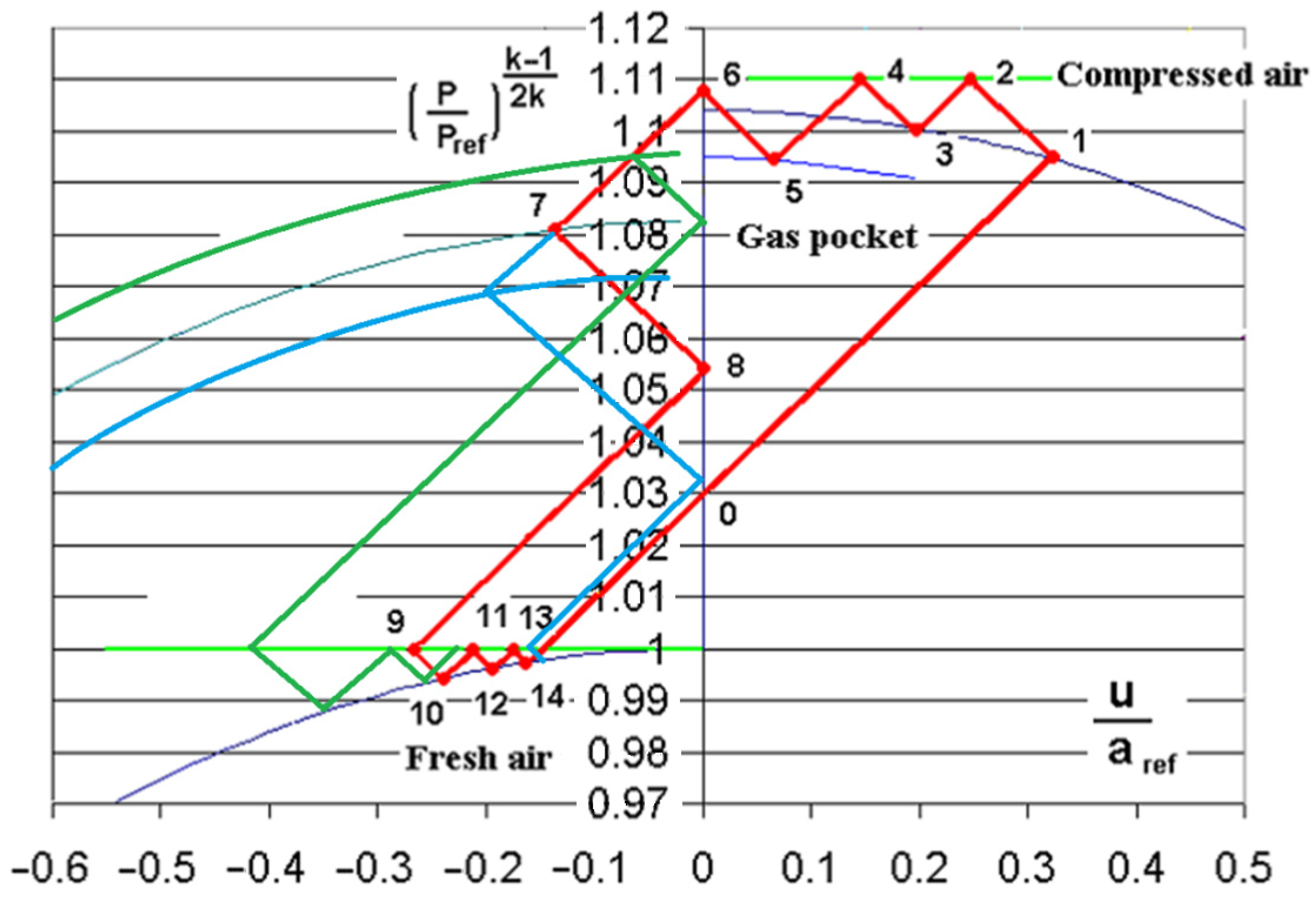
Figure 23 shows a diagram of the compression–expansion wave pattern in a two-stage compression system with a corresponding p-u (pressure–velocity) plane, along with the pressure and velocity distribution in the rotor channels in a plane and radial configuration, and the geometry of the engine channels above the combustion chamber.
Piechna, 2006 [
95], presented a wave disk micro-engine design, realizing one stage of shock wave compression, and its modification, which could be used to create a two-stage compression system. In this case, the replacement of steady-flow engine components with unsteady-flow devices was proposed and analyzed. It was shown that net power can be extracted from the rotor by using only a combustion chamber and a single radial rotor, applying oblique steady nozzles and straight blades to form rotor cells. The paper presented a mathematical model used in the 1D numerical calculation of wave processes in the wave engine models. The effect of wave attenuation in channels of very small dimensions was presented. The proposed idea was confirmed via a numerical simulation showing the potential range of operational parameters and the predicted engine efficiency (
Figure 23). It should be noted that the actual wave engine developed and build by Pearson, 1985 [
96], had an efficiency of about 10% at the operational point. Although the applied mathematical micro-engine model did not take into account all physical phenomena (heat transfer from the gas to disk walls was neglected, leakage in the disk case gap was omitted, and the gradual cell-opening process was not taken into account), the obtained numerical simulation results suggested that the micro-engine of the proposed construction was capable of delivering a net power at the micro-scale with reasonable efficiency. The work concentrated on the unsteady flow phenomena, and thus omitted the construction problems of bearing, heat transfer, and thermal stresses. It seems that this work provides a good basis for building more sophisticated 2D and 3D models using commercial codes like Fluent.
In retrospect, it can be said that the possibility of increasing the compression ratio by using two successive compression ratios on a single rotor was confirmed, while it was not possible to translate the gains from a high compression ratio to generate a greater rotor torque using this solution.
In an article by Piechna, 2006 [
97], the idea of a micro-engine design using only unsteady phenomena was presented, aiming to achieve an increased device efficiency compared to conventional steady-state flow machines. The proposition was validated via a 2D numerical simulation showing the potential range of operating parameters and predicted engine efficiency. The paper focuses on unsteady flow phenomena, ignoring the problem of bearing design, heat transfer problems, and thermal stresses in the structure. The paper proposes several possible modifications to MIT’s revolutionary engine design. The proposed design uses only a single radial disk, without any steady-state flow components (
Figure 24). The proposed solutions, on the one hand, aim to increase the efficiency of the original steady-state flow design in the combustion chamber by adding unsteady flow elements in a movable rotor. Instead of the simple miniaturization of conventional turbo-engine designs, a new bottom-up development idea was proposed, using a new wave disk proposal that is potentially more efficient at the micro-scale. The proposed bottom-up development, as opposed to scaled-down engineering, leads to engines that actually mimic their larger counterparts in terms of function and sophistication, but use completely different ideas and technology. Through this scaling down, unsteady flow devices show an increasing advantage over steady-state flow devices. It has been recognized that, at very small scales, only wave devices should be used, and at intermediate scales, there should be a suitable combination of both solutions. Because of the compact and relatively simple design of the device, complex models including unsteady flows inside the wave disk and a steady state in the case, allowing for heat transfer and perhaps fuel combustion, can be obtained using the available software. The range of Reynolds numbers expected during the operation of the device varies depending on whether a laminar and turbulent regime is used, and the effect of heat transfer must also be considered at a small scale, mainly by changing the local viscosity value of the medium. Such physical conditions present challenges for numerical calculations. The results of unsteady shock wave damping at the micro-scale are presented in
Figure 25.
The wave pattern and p-v plane for single-stage compression are shown in
Figure 26, and a possible design for a single-stage wave engine can be seen in
Figure 27.
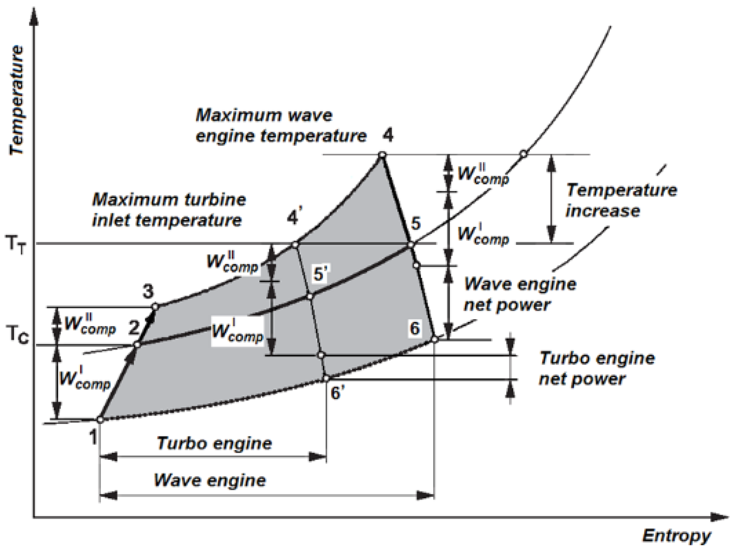
A schematic temperature–entropy diagram for a two-step compression turbo-engine and wave engine is shown in
Figure 28, and in
Figure 29, engine efficiency is presented as a function of disk rotational speed and combustion chamber heat release (two-step compression wave engine).
Figure 30 shows the pressure distribution in the channels of the micro-wave engine.
By using a slightly better system for the inflow of exhaust gas to the straight rotor blades, and calculating the two-dimensional flow in the rotor casing and ducts, it was possible to achieve higher engine efficiency, but, as can be seen in
Figure 29, this was associated with a need to increase the heat flux generated in the combustion chamber.
The paper by Iancu et al., 2006 [
98], presents several radial ultra-micro-wave rotor (UμWR) configurations and a numerical analysis of these rotors. In this paper, it was shown that the wave rotor technology has the potential to improve the performance of gas turbine cycles. Moreover, the radial wave rotor is an additional innovation of this technology. This has the benefit of using centrifugal forces to improve the compression process or flow-scavenging. The rotor geometry is much simpler and ideal for micro-fabrication, which relies mainly on two-dimensional processes to create three-dimensional features. In a radial placement, the wave rotor has four possible configurations with two general categories, through- and reverse-flows, each of which could have the low-pressure air port positioned inside or outside of the rotor (
Figure 31). A possible design of such a wave engine type is presented in
Figure 32. The numerical results were obtained using FLUENT and commercial code. Basic information about the unsteady processes occurring during simulation is visualized (
Figure 33).
One major problem encountered in the operation of wave pressure exchangers is the need synchronize the speed of the movement of the rotor channels with the dimensions of the windows in the rotor housing. This problem has been known for a long time and attempts to solve it have included the use of additional cavities in the housings (Mayer et al., 1990 [
99]).
Piechna and Dyntar, 2008 [
100], analyzed a wide range of concepts for wave disk micro-motors, applying 1D and 2D simulation codes. Due to the goal of further miniaturizing the device, the wave disk geometry (radial displacement of the disk compression-decompression channels) was considered the main configuration. In the radial scheme, the disk required a larger diameter but could be flat and thin. The wave engine design study focused on two main problems: the realization of gas compression and the simultaneous torque generation on the same set of rotor channels. Only purely unsteady operations were considered.
Regarding the efficiency of unsteady processes, the length of the compression–decompression channels should be ten times the width of the channel. This ratio is necessary to reduce the influence of the finite time during the channel-opening process.
However, in the case of torque generation, a high ratio of channel length to width is not very useful, especially in the case of fixed-width channels. Curved channels have been used to increase the actual length and reduce the rotor speed required for synchronization. The rotational speed of the disk was three times lower than that of comparable steady-state machines.
Figure 34 presents exemplary 1D simulation results and
Figure 35 shows the results of 2D simulations. The highest speed of the rotating components was three times lower than that in steady-state machines. Compression under such conditions is more efficient that obtained under unsteady conditions, but the decompression time is no longer. Locally, the gas velocity reached 300 m/s, but it was overall much lower. Due to the unsteady flow conditions, the torque varied strongly over time.
When the unsteady processes were mixed with the centrifugal and Coriolis forces known from the steady-state machines, it was difficult to predict the final results. The unsteady process of gradual opening at the channel ends provided information about additional unsteady forces that occurred due to the uneven distribution of pressure acting on the disk in the two-dimensional model. This problem was noted earlier and considered in large wave rotors in the work of Eidelman, 1985 [
101], and 1986 [
102,
103].
The general conclusions of these analyses boiled down to the confirmation of earlier findings. There is no problem with obtaining high pressures using the compression process. The problem of effective torque generation remains unresolved. It can be generated but its magnitude is not satisfactory.
Unfortunately, the experience gained in the design of steady-state machines is not very useful in the case under consideration. The main problem associated with wave motor operation is still its poor scavenging capabilities. Due to the relatively low rotational speeds, the centrifugal forces are not very strong, but in many of the analyzed cases, they effectively carry out the scavenging process. The purification process under such conditions occupies a significant portion of the disk space. Therefore, the energy density associated with the disk volume is relatively low. A wave disk can be an effective compression device, so combining it with a combustion chamber can create an efficient gas-generator, but a wave engine design based solely on unsteady processes cannot be used to create an efficient device. It is possible to generate torque with a certain wave disk geometry, but this is not as efficient as steady-state operations.
6. Hybrid Wave Disk Micro-Engines with an External Combustion Chamber
In order to bypass the problem of insufficient torque value being generated on the wave rotor shaft, another solution was sought, changing the purpose from torque to thrust generation.
The article by Piechna and Dyntar, 2007 [
104], pursued the design of a wave disk jet engine, showing some 2D numerical simulations results for the basic parameters of the flows inside. The temperature of the hot gas in the considered wave engine varied from 1300 K to 2000 K. Such high temperatures were taken into account, along with the benefit of the potential self-cooling properties of the wave disk. Each cell wall was loaded with high-temperature gas for a very short time, and then immediately cooled with fresh air. The highest temperatures were recorded in areas of the rotor housing in the part that delivers hot gases to the rotor chambers. Since the high-temperature gas in the enclosure was confined to a very small area, special temperature-resistant materials can be used in only these areas.
The stable operation of the jet micro-engine was confirmed with respect to the full flow structure inside the device; it turned out that this engine, with an unusual design, can operate in a stable mode. In order to achieve this, the amount of heat that is supplied must be large enough to increase the temperature of the compressed air to a minimum value of about 1300 K. In the radial disk configuration, a compression ratio of about 4 can be achieved, depending on the amount of heat supplied and the rotor’s rotational speed. A wave engine with a diameter of 15 mm and a thickness of 3 mm, with an estimated mass of 0.6 g, can generate an average thrust of 0.7 g.
In the 2D numerical model, the presence of the combustion process was simplified to the use of a heater that locally increases the air temperature to the expected level. Rotating disk channels were simulated using a moving mesh technique. The existence of centrifugal force and Coriolis force was taken into account.
Figure 36 presents a flow-field scheme with a velocity distribution and an expanded view of the proposed engine design.
Any turbo-engine cycle contains the following basic thermodynamic processes: compression, heat addition at constant pressure, and expansion. Investigations of micro-engines revealed the problem of inefficiency due to the use of steady compression devices, proposing the application of unsteady devices for gas compression. The potential advantages of wave rotor engines in terms of the increased maximum temperature and increased net power are evident.
Numerous theoretical and numerical investigations of pure wave engines are documented in the papers of Piechna, 2005 [
94], Piechna, 2006 [
95], Piechna and Dyntar, 2008 [
100], and Piechna and Dyntar, 2007 [
104]. The construction of a wave engine based only on unsteady processes utilizes the advantages of unsteady compression. However, when the same phenomena occur in the decompression part of the process, this decreases the torque-generation ability. Thus, a new hybrid engine concept was developed, as presented below.
Piechna and Dyntar, 2010 [
105], exploited the positive characteristics of steady and unsteady flows. The advantage of the unsteady wave-compression process over the steady-state one, as well as the significant advantage of the gas expansion in the steady-state process compared to the unsteady one, were demonstrated. By using centrifugal forces, the chambers of a wave rotor can be emptied when the unsteady process is abandoned. The realization of such a mixed-flow scheme was shown in the example of a hybrid motor design that uses the positive features of both unsteady and steady-state flow processes.
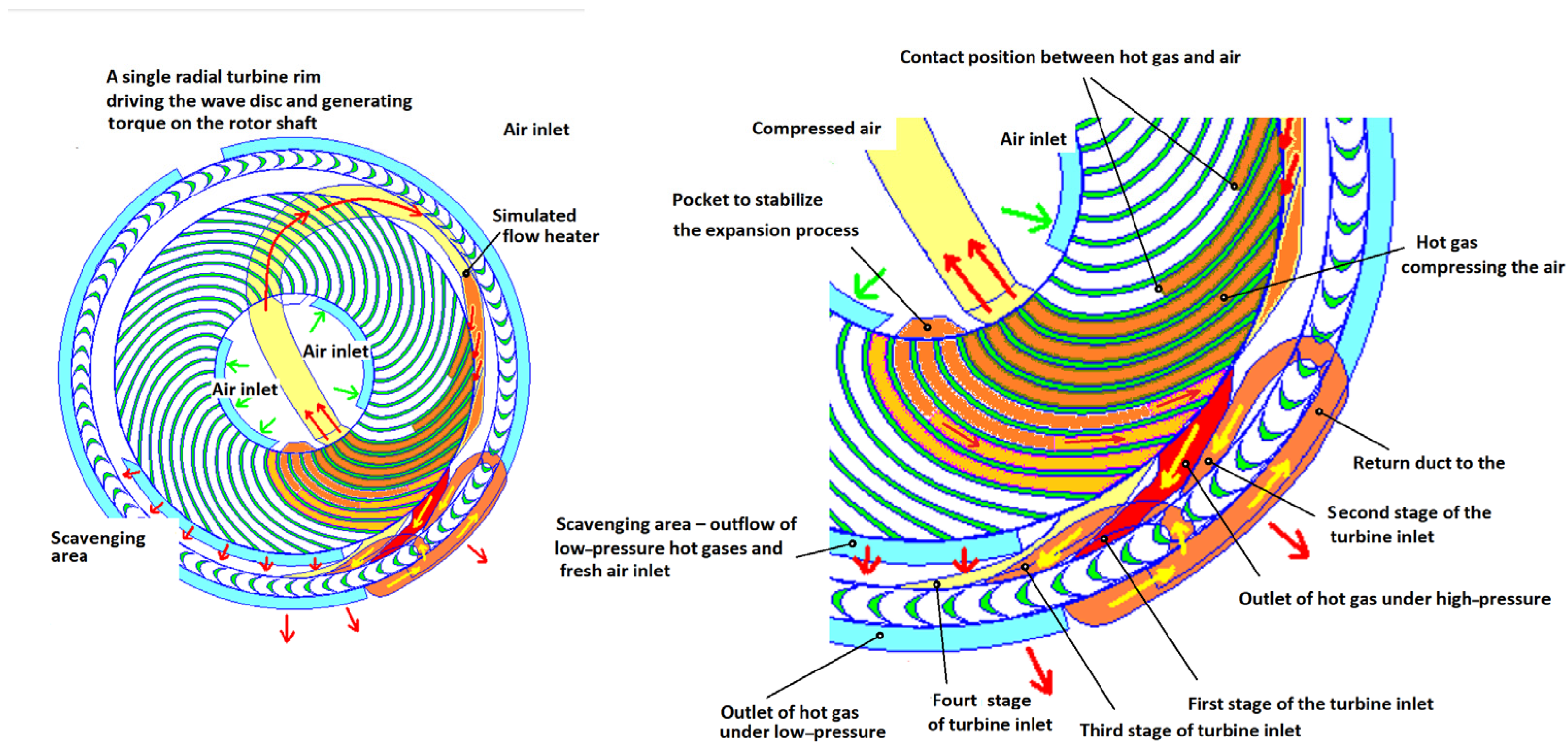
As stated, this new concept of a hybrid wave engine and the process numerical study can be used to create a single machine that can be used for all the necessary functions, i.e., unsteady compression, steady expansion, and mixed unsteady and steady scavenging assisted by centrifugal forces. As mentioned, this new concept of a hybrid wave engine and the presented results of numerical studies of the physical processes involved in it, can be used to build a single machine that can use effectively transient processes for compression and equally effectively steady-state processes for expansion and operate in the presence of both centrifugal and Coriolis forces to support the scavenging process. A numerical two-dimensional complete model of this device was developed, and several numerical simulations of the engine operation were carried out. The numerical model included a simplified model of the combustion chamber that enables a closed-loop flow between the high-pressure compressed air port and the high-pressure hot exhaust port. The model created a complete flow diagram of a hybrid wave engine. A special type of turbine in a radial configuration with a series flow system was used to generate torque. The basic performance of such an engine, along with its power and efficiency, was presented.
Figure 37 shows the basic differences between the compression and expansion processes implemented in steady-state and unsteady processes. The advantages and disadvantages of each method of compression and expansion are shown. In
Figure 38, the wave pattern and physical plane (p-v) diagram is presented.
The specific scheme realized in this project, with high enthalpy and low mass flow rate, required special treatment and the use of multiple flows of the same outlet stream through the same radial turbine rim, as shown in
Figure 39 and
Figure 40.
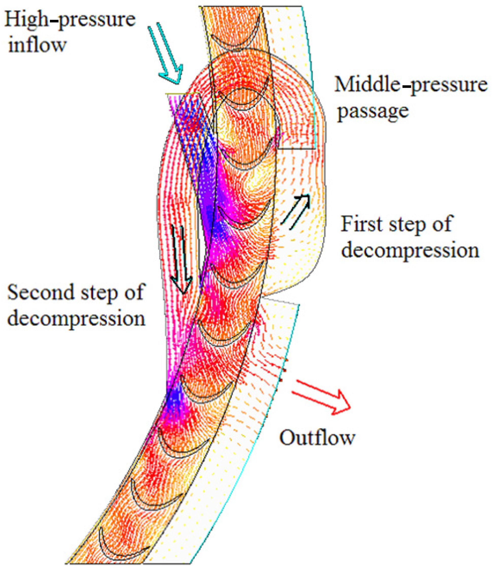
A diagram of the internal flows inside the wave engine is presented in
Figure 41, and details of the flow pattern visualized with velocity vectors are shown in
Figure 42.
The calculations of the two-dimensional hybrid wave engine model were performed using Fluent code and the results confirmed the expectations. By only using a single moving part, which contains a set of radial channels of the gas-generator, and a single row of radial turbine blades, it was possible to obtain the net power using a stable operation from the gas-generator unit. Without even optimizing the elements of the torque-generator for the blade shape, dimensions, or angles of nozzles, the generated torque showed reasonable values. The efficiency, defined as the ratio of the generated mechanical power to the delivered heat power, reached 10%. It was thus shown that a wave machine can operate effectively as an autonomous gas-generator. The gas-generator unit, once self-driven, can be mechanically separated from the torque-generator unit. In such a configuration, a typical radial or axial turbine can be used as a torque-generator device. Since the simplicity of the solution was the most important device feature in this project, a single rotating disk construction was analyzed.
Taking into account the results achieved in this investigation, the design of a hybrid engine demonstrator with a power range of 1000 W seems possible. The disk diameter of such a demonstrator should be about 15 cm, with a thickness of about 3 cm. At this scale, conventional techniques can be used for steady and unsteady measurements of pressure, gas velocity, and temperature.
This would be an intermediate step before designing a smaller, 3 cm diameter model. A hybrid engine made using MEMS technology with a diameter of 15 mm and a thickness of 3 mm can generate 20 W of mechanical power with an efficiency of about 10%.
It should be noted here that the specified values were achieved with a single-stage compression process. In addition, it can be noted that the main limitation in the operation of the turbine in a steady-flow process was removed in this solution, since the blades of the ring turbine were only temporarily exposed to the high-temperature exhaust gas, as the partially expanded cooled exhaust gas cooled the turbine blades in subsequent flow cycles through the same rotor. In addition, the slowly rotating turbine was exposed to much less centrifugal force loading.
To conclude, unsteady compression is more efficient than steady compression, whilst steady expansion is more efficient than unsteady expansion.
In the engine design of Pearson, 1985 [
96], one can see structural elements fulfilling similar roles as the unsteady and steady flow elements. It should be noted here that, at the time, this was the only design that generated an acceptably useful amount of torque and power, although the descriptions of the principle of its operation were not entirely clear.
7. Internal Combustion Wave Micro-Engine
The idea of using the combustion process at a constant volume is quite old. It has been studied in large machines with wave rotors since the 1990s [
106,
107,
108,
109,
110,
111,
112,
113,
114,
115,
116,
117,
118]. The first large-scale experimental work was carried out in Switzerland [
119].
In the paper of Vagani et al. [
120], in 2009, the concept of a wave disk engine with internal combustion was presented. The wave disk engine combines the principles of the wave engine and wave combustor. The wave disk engine uses a radial-flow wave rotor or wave disk. The wave disk is particularly suited to microfabrication as it has a simple extruded 2D geometry with a short depth. The wave disk also allows for curved channels, which will allow the rotor to extract energy from the flow. The authors pointed out the mechanical simplicity of the engine concept, with only one rotating part, which allows it to be miniaturized without many of the technical issues faced by other small-scale gas turbine engines.
The simulation results for a disk of 10 mm outer diameter and 6 mm inner diameter, rotating at 200,000 rpm, are presented in
Figure 43.
Figure 44 presents the p-v and T-s diagrams obtained via 2D simulation.
Four separate numerical methods (the quasi-1D algebraic algorithm, 1D wave disk engine model in GT-POWER, quasi-2D CFD code, and 2D CFD FLUENT code) were used to model the wave disk engine. Each of the preliminary results confirms that the concept of the engine is feasible.
Due to the existing high interest in the need for small-scale power generation and the notoriously low efficiency of small-scale energy conversion, the work of Akbari et al., 2008 [
121], highlighted the relative advantages of non-stationary wave flows in generating efficient compression processes (see
Figure 45). The possibility of using pulsed combustion in disk-shaped geometries to generate mechanical energy was presented. An analysis of the physical and chemical issues involved in the operation of such devices is presented. A new kind of small-scale combustion engine is introduced, in which a nearly constant volume combustion is achieved inside the narrow channels of a disk with curved blades that allows for extraction during expansion. The overall thermal efficiency of the engine is expected to be superior to that of the scaled-down versions of conventional gas turbine engines and piston engines. The internal combustion wave disk engine and its advantages over other small-scale combustion engines are described. It further discusses the challenges faced by small-scale engines, and the possibility that the use of the wave disk engine as a combustion device can address many of these challenges. The inherently unsteady nature of the flow, coupled with the traveling pressure waves and pulsed combustion, might help the wave disk engine to counter many of the drawbacks faced by small-scale combustion engines.
The work of Kurec et al., 2014 [
122], concerned the use of an atypical fuel, presenting a numerical analysis of the flow and combustion phenomena inside a radial disk internal combustion engine. In the set of cambered chambers that form the engine disk, a mixture of hydrogen peroxide with hydrogen was burned under constant-volume conditions. The thermal decomposition of hydrogen peroxide at a 70% concentration was used as a pilot in the stabilizing process of hydrogen combustion, effectively addressing important challenges faced by channels with small dimensions. H
2O
2 thermal decomposition is a source of oxygen for hydrogen combustion. The cycle consisted of the filling process, which was preceded by a cooling and separation process that was realized through the injection of a water steam, combustion, and an expansion process. In the considered numerical model, the cycle was simulated numerically with the commercial software package FLUENT, which allows for the tracking of species and chemical reactions. The implemented model considered problems in sealing, ignition, and quenching. The results of the simulations were presented in the form of pressure, temperature, velocity, and species concentration contours, as well as torque variation over time.
A safe decomposition process was provided through the use of hydrogen peroxide at a 70 percent concentration, which was not high enough to lead to a self-decomposition process.
The following reactions were defined:
2H2O2 -> O2 + 2H2O.
- 2.
Hydrogen combustion:
2H2 + O2 -> 2H2O.
The basic dimensions of the engine disk are as follows:
Disk internal diameter = 40 mm.
Disk external diameter = 50 mm.
Rotational speeds were studied in the range of 500 rad/s ÷ 10,000 rad/s, which corresponds to the range of velocities at the outer diameter of 14 m/s ÷ 300 m/s. After analyzing the results, a rotational speed of 5000 rad/s was chosen for the calculations with a full model.
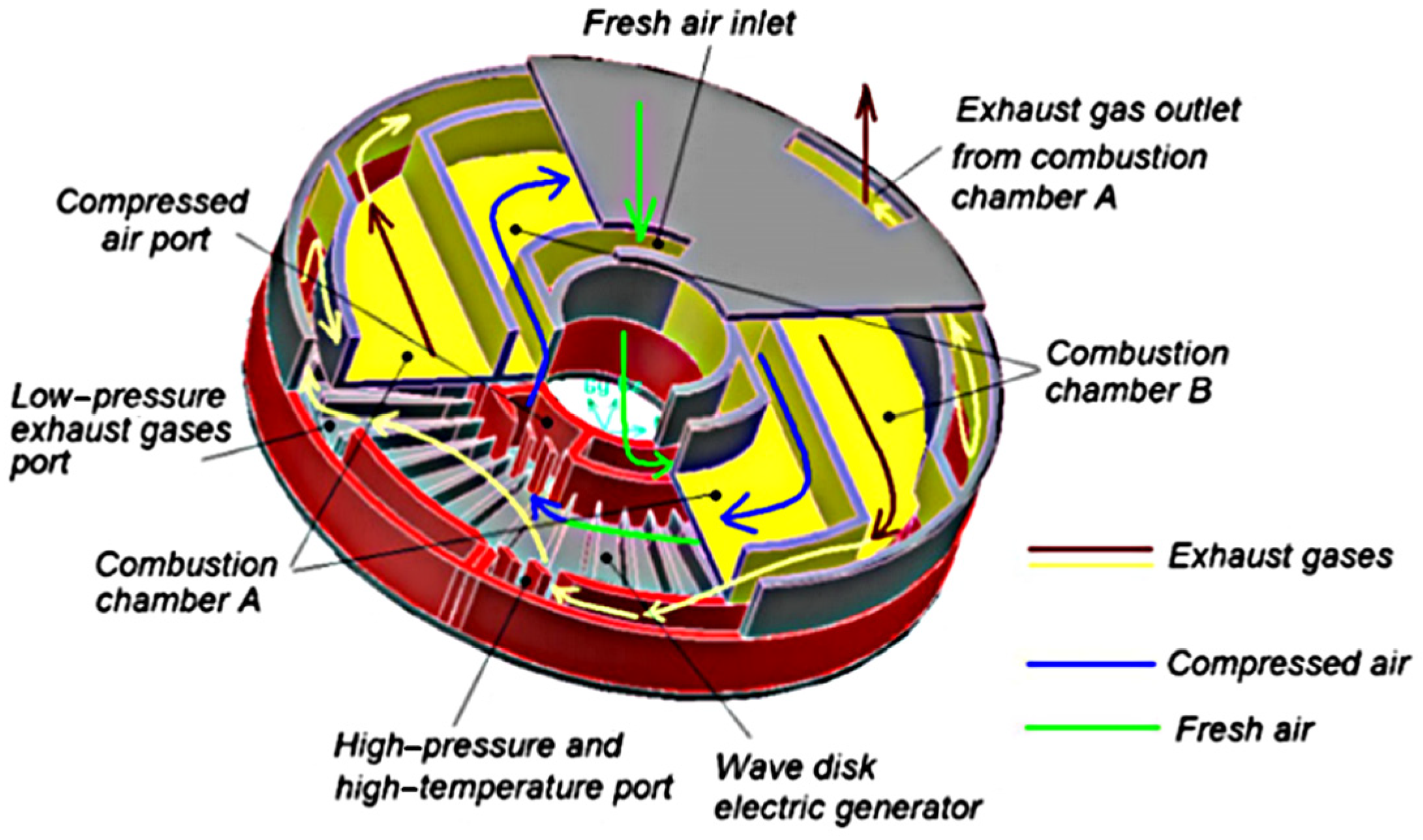
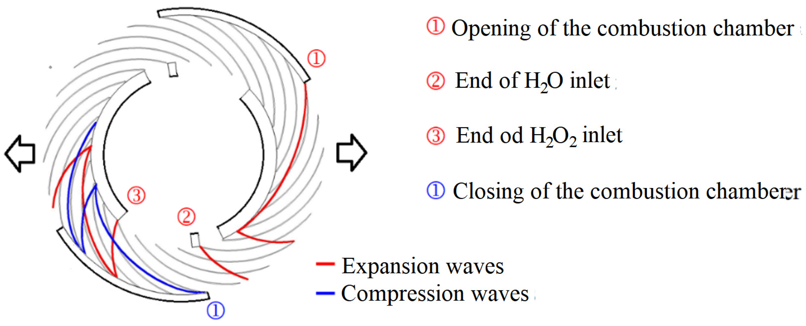
Figure 46 shows the distribution of channels in a disk with two duty cycles per revolution. The design ensures the separation of fuel and exhaust gases and cooling through water injection, fuel injection, ignition, isochoric combustion with pressure increase, gas expansion and exhaust.
Figure 47 shows the schematic layout of the compression and expansion waves of gases in the engine rotor channels.
Figure 48 visualizes the distribution of static pressure in the rotor channels and
Figure 49 presents the accompanying temperature distributions.
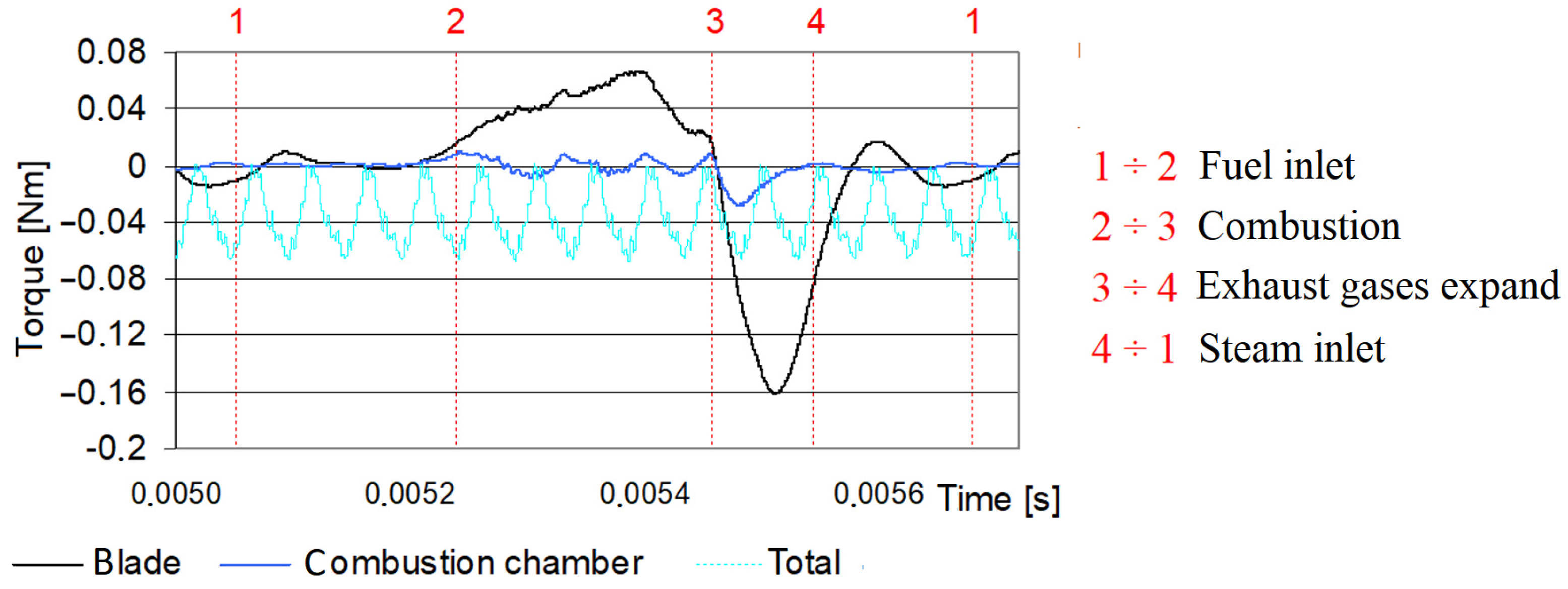
The plots of the torque generated by selected parts of the rotor are shown below in
Figure 50. These include the following:
- ▪
The torque generated on the walls of one blade.
- ▪
The torque generated on the walls of one combustion chamber.
- ▪
The total torque generated on the rotor.
Additionally, the main phases of the engine’s operation are marked in the diagram.
A negative sign for the torque represents a useful torque. The influence of closed combustion chamber angle (indirectly representing the time of the combustion process) was investigated.
The effect of the perimeter length of the outer wall of the engine casing, which ensures the process of hydrogen peroxide decomposition and hydrogen combustion under constant-volume conditions, was tested.
Figure 51 shows the values of the average torque for different values of this geometric parameter.
Two cases of torque generation were compared. One underwent 40° and 70° constant-volume combustion. The reason for this choice was the large difference in mean gage pressure, which only resulted in a small change in the generated torque.
The designed wave engine generated 180 W power with an efficiency of 5.8%. It should be noted here that the calculations take into account the reception of heat by the engine housing and the heat caused by the exhaust gas flowing out of the engine. Because of the inefficient torque generation due to the unsteady expansion, a modification of the engine was realized, extracting 22% of the initial mass flow rate at a pressure of 2.5 bar and reducing the generated power to 110 W.
An unnoticed but important feature of the presented solution is the generation of clean exhaust gases (water) without harmful compounds such as NOx, which are formed during the combustion of classical petroleum-based fuels.
8. Other Applications of Small Wave Disks
Radial wave disks have also been frequently applied in refrigeration. The article by Feng et al., 2024 [
123], presents the first application of radial impellers in refrigeration. The article presents the advantages of such geometries and the weaknesses. Axial (
Figure 52) and radial (
Figure 53) geometries were contrasted and evaluated.
The paper demonstrates the advantages of radial configuration in a wave rotor, such as the ability to simplify the cooling process by taking advantage of the centrifugal forces in the radial rotor channels. The radial configuration not only streamlines the cooling process, but also facilitates multi-cycle cooling. It was pointed out that radial wave gas chillers show greater utility under high-flow or high-pressure conditions. Attention was drawn to the occurrence of the Coriolis effect, which increases or decreases the impeller drag torque depending on the direction of flow in the channels. Increasing the impeller speed or cycle efficiency results in increased energy consumption. The main advantage of the radial configuration chiller is its ability to carry liquids, resulting in its high efficiency in transporting wet gas. The radial structure of the rotor can effectively use the centrifugal effect to remove condensed droplets. This improves the separation of dry gas from droplets, thus improving both the cooling efficiency and effectiveness of separation. However, compared to axial structures, the complexity of condensation issues in radial structures is greater.
9. Final Remark
This paper presents many solutions that went unnoticed, were not understood, or were forgotten. Currently, there are many works that repeat errors shown in earlier works.
The possibility of obtaining much higher compression ratios through gradual compression processes in an unsteady manner leads to an increase in micro-engine efficiency, but involves the need for particular solutions for torque generation; for example, slow-speed turbines with multiple flows of the same medium in successive expansion processes. It should be noted here that such a solution leads to the occurrence of a self-cooling process in the stationary flow through the turbine.
It seems that the idea of a hybrid engine that combines the advantages of compression in a transient process and torque generation in a steady-state process in a special low-speed ring turbine, providing several stages of expansion on a single rotor rim and thus allowing for the blade to self-cool, which allows for the application of higher exhaust gas temperatures in the turbine, which, due to its low speed, is loaded with lower centrifugal forces, was not noticed, or was not understood and forgotten.
In the case of a hybrid engine, the energy stored in the high-pressure, high-temperature exhaust gas remaining in the rotor ducts must be divided between the stationary and non-stationary expansion process needed to clear the channel of exhaust gas and fill it with new air.
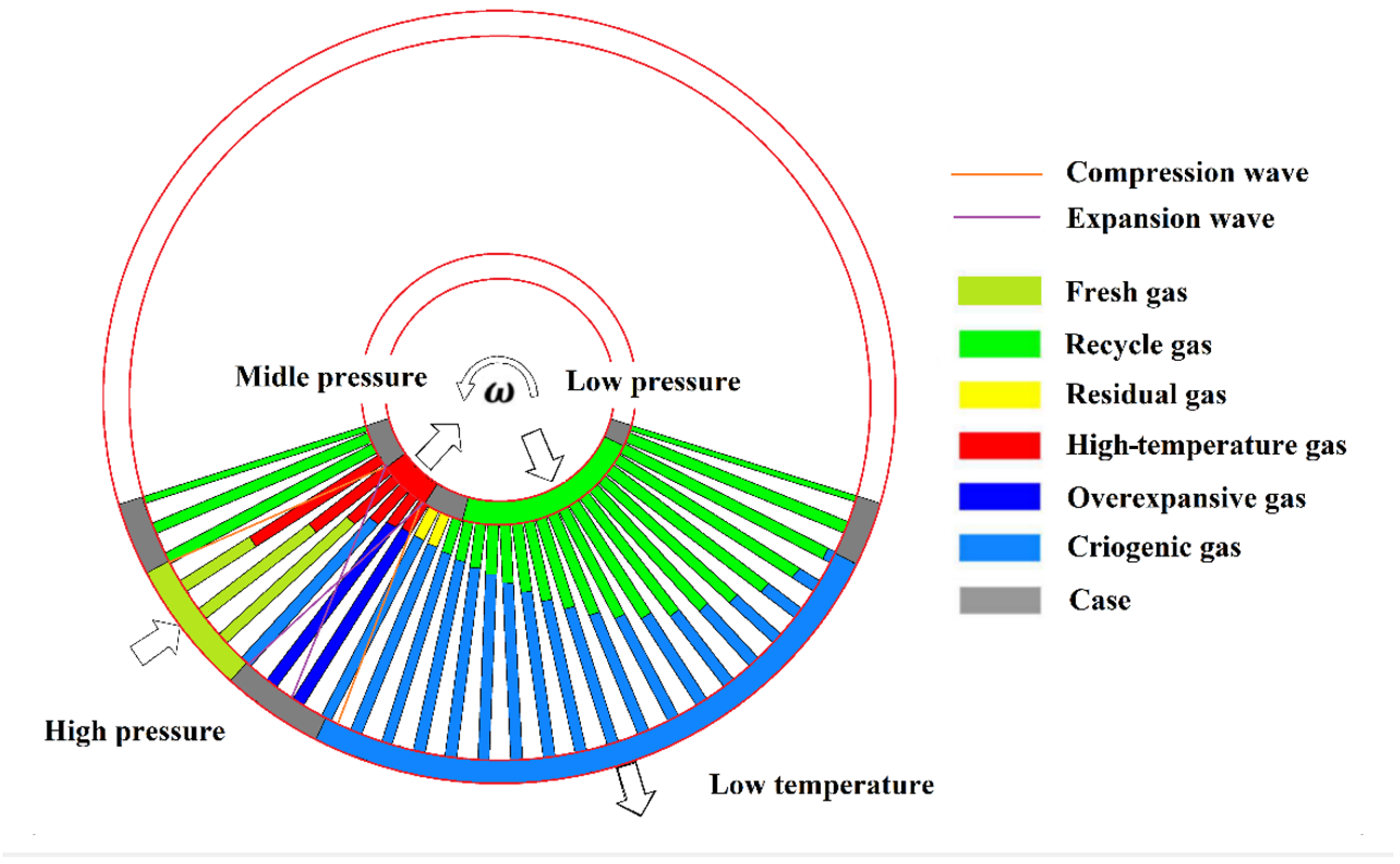
As can be seen in the modified
Figure 54, we can choose either a small exhaust gas output with higher pressure, which improves the process of emptying the rotor exhaust gas and filling it with fresh air, or a larger exhaust gas output with lower pressure, which leads to a worse, longer process of cleaning the rotor exhaust gas and filling with air. One arrangement was numerically tested in Reference [
105]; the micro-engine efficiency was not bad, but it was unclear whether the proportions were optimal. A rotor with radially aligned channels can improve the exhaust-to-air exchange process using centrifugal forces rather than the inertia of the medium.
There are still many unproven possible ways to obtain globally higher efficiencies in micro-engines. It seems that studying the results of older works and understanding them may lead to completely new solutions and research directions.
10. General Conclusions
Heat engines are a promising source of energy at the micro-scale due to their high efficiency and high energy density. However, we cannot simply apply the advanced technology of conventional engines, such as gas turbines and automobile engines, at the micro-scale. We need to develop design and manufacturing technologies that can identify and account for the effects of Reynolds number and heat transfer. In addition to the problem of fuel tank location, there are other environmental issues related to controlling the high-temperature heat core inside the micro-structure to effectively regenerate the heat flux.
A promising solution is the use of moving waves in the flow, instead of relying on a change in state based on the conventional steady flow of compressible gas in a thermodynamic cycle. In particular, compression via pressure waves, i.e., shock waves, is efficient and is not affected by the miniaturization of the device dimensions. In this review, we focus on wave rotors, primarily known for their use in diesel engine supercharging systems, and conduct research to gather useful information in order to clarify the principles of internal wave flows through examining the impact of their miniaturization and their further development in micro-thermal engines.
We compiled this information in the attached literature list, with the following summary points that we hope will be helpful:
The wave rotor has only few limitations in terms of miniaturization due to its operating principle and has a high tolerance for a variety of manufacturing processes and materials. It also exhibits high resistance to temperature and mechanical loads on the rotating components. Consequently, there is great freedom in the design and geometry of systems integrated into the combustion chamber when used in gas turbines or reciprocating engines.
Generally, the rotational speed of wave rotors or wave disks under similar flow parameters is slower than that of conventional steady-state machines.
Due to the periodicity of the flow, wave rotors are characterized by the property of self-cooling.
This feature is particularly important when the flow device has small dimensions and is made of a material with high thermal conductivity (germanium, silicon).
Wave rotor channels can be arranged both axially and radially to the axis of rotation, which is an effective way to carry out the compression process using moving waves.
The wave rotor and wave disk have the unique property of being able to form a cascade compression system on the same rotating element, which is impossible in conventional steady-flow devices.
Although occurring simultaneously, the two processes in a wave rotor—the compression process and the expansion process of the medium—should be treated separately.
Compression using an unsteady process is always more efficient than that obtained using a steady-state process.
Expansion using the unsteady process always generates less kinetic energy at the outlet compared to the steady-state process.
Expansion in a steady-state process causes it to be staggered and, due to the lack of inertial forces in transient motion, the resulting gas velocity is twice that of a steady-state process.
The aforementioned disadvantages of an unsteady expansion process are not always a real disadvantage, as, in some processes, the gas inertia effect is used to speed up the process of filling the rotor channels with new medium.
The challenge when using a wave rotor is the process of scavenging the channels and replacing hot exhaust with cold air when the inertia of the medium is used.
In a radial system, the inertial forces generated by a properly selected flow system ensure the rotor channel is emptied.
The use of a rotor channel to generate torque is possible regardless of the shape of the channel (straight or curved), but this is an inefficient solution.
To take advantage of the beneficial features of both steady-state and transient processes, a hybrid solution can be used in which the compression process is implemented as an unsteady process and the expansion process runs as a steady-state process.
When the gas flow rate through the casing outlet port is low, it is necessary to use special slow-speed turbines that can take advantage of the high pressure and gradually expand the gases in stages on the same turbine rim.
The potential of hybrid engine solutions that use the wave process for compression has yet to be fully exploited.
The flow processes in radial rotors are complicated and have not been fully studied, as there is a complex interplay of transient wave processes, centrifugal forces, and Coriolis forces in the rotor channels, which modify the shape of the contact surfaces of gases with different temperatures and densities.
The use of new energy carriers, such as hydrogen peroxide and hydrogen, offers the possibility of building engines that generate clean exhaust gases without NOx, CO, and CO2.
Micro-heat engines with high-temperature operation and other cryogenic devices for refrigeration have many expected applications.

