Article

Multi-Frequency Time-Sharing Strategy to Achieve Independent Power Regulation for Multi-Receiver ICPT System

1
School of Marine Science and Engineering, Shandong University of Science and Technology, Qingdao 266590, China
2
The State Key Laboratory of Precision Measuring Technology and Instruments, Tianjin University, Tianjin 300072, China
*
Author to whom correspondence should be addressed.
These authors contributed equally to this work.
Energies 2025, 18(6), 1389; https://doi.org/10.3390/en18061389
Submission received: 11 February 2025 / Revised: 8 March 2025 / Accepted: 10 March 2025 / Published: 11 March 2025
(This article belongs to the Section F: Electrical Engineering)

Abstract

:
The diverse array of sensors deployed on meteorological observation towers, tasked with the observation of meteorological gradients, requires distinct power supplies and effective power regulation. In this article, a multi-frequency, multi-receiver (MFMR) inductively coupled power transfer (ICPT) system using a time-sharing frequency strategy is proposed, which enables coupled power transfer to multiple nodes through only one cable. The time-sharing frequency control (TSFC) method is introduced to produce time-sharing multi-frequency currents. By incorporating a controllable resonant capacitor array at the transmitter, the system can operate at various resonance frequencies over specific intervals, allowing it to supply power to multiple loads with unique resonance frequencies. First, an in-depth analysis of the power transmission characteristics of MFMR-ICPT systems is conducted, with the three-frequency, three-receiver (TFTR) ICPT system circuit serving as an example. The frequency cross-coupling effects are then analyzed, and the TSFC method is explained. Finally, experiments are conducted on a TFTR-ICPT system. The results demonstrated that independent power regulation of multiple loads could be achieved by adjusting the duty cycle of different frequency input voltages through the time-sharing frequency strategy. The system achieved a total power output of 38.7 W, with an efficiency of 64.8%.

1. Introduction

Meteorological observation towers are typically constructed in coastal areas to monitor meteorological gradients. These towers house an array of sensors for measuring wind speed, temperature, humidity, and pressure, mounted at various heights to capture data across different levels [1,2,3]. Sensors on these towers typically rely on wired power supplies or batteries. However, the need for separate cables for power and communication for each sensor results in a complex wiring configuration, creating significant maintenance challenges.
Inductively coupled power transfer (ICPT) technology enables contactless charging, ensuring a safe and flexible process [4,5,6]. ICPT technology is currently applied in autonomous underwater vehicles, remotely operated underwater vehicles, and electric vehicle charging [7,8,9]. However, these ICPT systems can typically charge only a single device at a time. As ICPT technology has advanced, its applications have expanded from single-frequency, single-receiver to single-frequency, multi-receiver power supplies. However, research on multi-frequency, multi-receiver (MFMR) ICPT systems remains limited, with most studies focusing on single-frequency, multi-receiver ICPT systems [10]. MR-ICPT systems have previously been used in mooring and underwater buoys [11,12,13]. Due to cross-coupling among multiple loads, achieving the desired power distribution between loads is unfeasible.
Due to the diversity of parameters monitored by the meteorological gradient tower, various types of sensor equipment are installed at different heights on the tower. Table 1 presents the types and power consumption of various sensors installed on the tower, indicating that the power requirements for sensors at different elevations on the meteorological gradient tower vary. To provide a safer, more flexible power supply for meteorological observation towers, an MFMR-ICPT system was designed, as shown in Figure 1. This system is capable of simultaneously powering multiple tower equipment with varying power requirements, enhancing the system’s reliability and versatility. The system is mounted on the tower via a long cable and uses coupled magnetic rings at various heights to enable contactless power supply. However, cross-coupling [14] between loads can result in fluctuations in power supplied to each load. Issues with coupling, especially when load conditions change or external environmental factors are introduced, can lead to variations in power supply to the sensors. Consequently, there is a pressing need for robust power distribution technology that can meet the varying demands of each load in the MFMR-ICPT system.
Research on power distribution technology in multi-receiver ICPT systems has made significant progress. Generally, MR-ICPT systems are classified as a single-frequency, multi-receiver (SFMR) ICPT system and an MFMR-ICPT system. In an SFMR-ICPT system, the transmitter’s resonant frequency matches that of multiple receivers. Consequently, the output power of the transmitter’s load changes in response to variations in resistance [15,16]. In [17], the authors present a method for achieving a multi-receiver, previously compensated, cross-coupled constant-current output, which achieves independent output control of the system by adaptively compensating for the cross-coupling in the system. The MFMR-ICPT system is an important approach for achieving load power distribution [18]. For load power distribution, the MFMR-ICPT system requires multiple transmission channels with distinct frequencies, achieved by superimposing currents of different frequencies at the transmitter. Transmission methods in the MFMR-ICPT system fall into two main categories: multi-inverter parallel technology and single-inverter technology. Multi-inverter technology uses multiple inverter stages at varying frequencies to generate multi-frequency superimposed currents, though it creates a highly complex transmitter structure [19]. A single inverter can create multiple power channels with simultaneous output of fundamental frequencies and harmonics, yet it does not permit independent load power control via inverter adjustments [20]. The hybrid sinusoidal pulse wave modulation (HSPWM) method generates multi-frequency currents and allows independent system regulation through a single inverter [21]. However, achieving high system efficiency is challenging, given the need for high carrier frequencies. Superposition multi-frequency modulation technology can achieve independent load power regulation [22,23]; however, it often requires complex online calculations and experiences cross-coupling between frequencies, affecting load output power. Multi-frequency power sharing technology cannot output power at multiple frequencies simultaneously, but it can switch between frequencies rapidly, enabling asynchronous charging for loads with distinct frequencies [24,25]. In cases of significant cross-coupling between loads, multi-frequency power sharing technology can effectively decouple power transmission. In [26], the authors present an MFMR-WPT system that is based on hysteresis loop current (HC) control to output multi-frequency power by controlling the superposition of different frequency currents. The system has the capacity to output multi-frequency power in a stable manner and can switch the power frequency at will. In [27], the authors achieve dual-frequency modulation by utilizing a transmitting coil as an alternative to an inductor within the power converter and by superimposing a sinusoidal signal on the converter’s control signal. This results in a current that comprises both a switching frequency component and a sinusoidal frequency component. Furthermore, the MFMR-ICPT system, which is capable of achieving multiple load outputs through the utilization of multi-frequency modulation techniques, frequently necessitates the employment of sophisticated multi-frequency modulation techniques and high-cost components. In [28], a minimum of four switches are required at the transmitter.
To enable the controlled powering of multiple sensors on the tower, this article proposes a time-shared MFMR-ICPT system using long cables. The time-sharing frequency control (TSFC) strategy undergoes comprehensive analysis, with a single inverter used to generate multi-frequency current alongside a controllable resonant capacitor array at the transmitter. Selective operating frequencies eliminate the need for additional wireless communication circuits. Each receiver resonates at the operating frequency during conduction, with the load output power distribution determined solely by the duty cycle of each system frequency. Experiments were conducted using a three-frequency, three-receiver (TFTR) ICPT system prototype, confirming the system’s viability and efficacy in load output power distribution. Finally, conclusions are drawn.

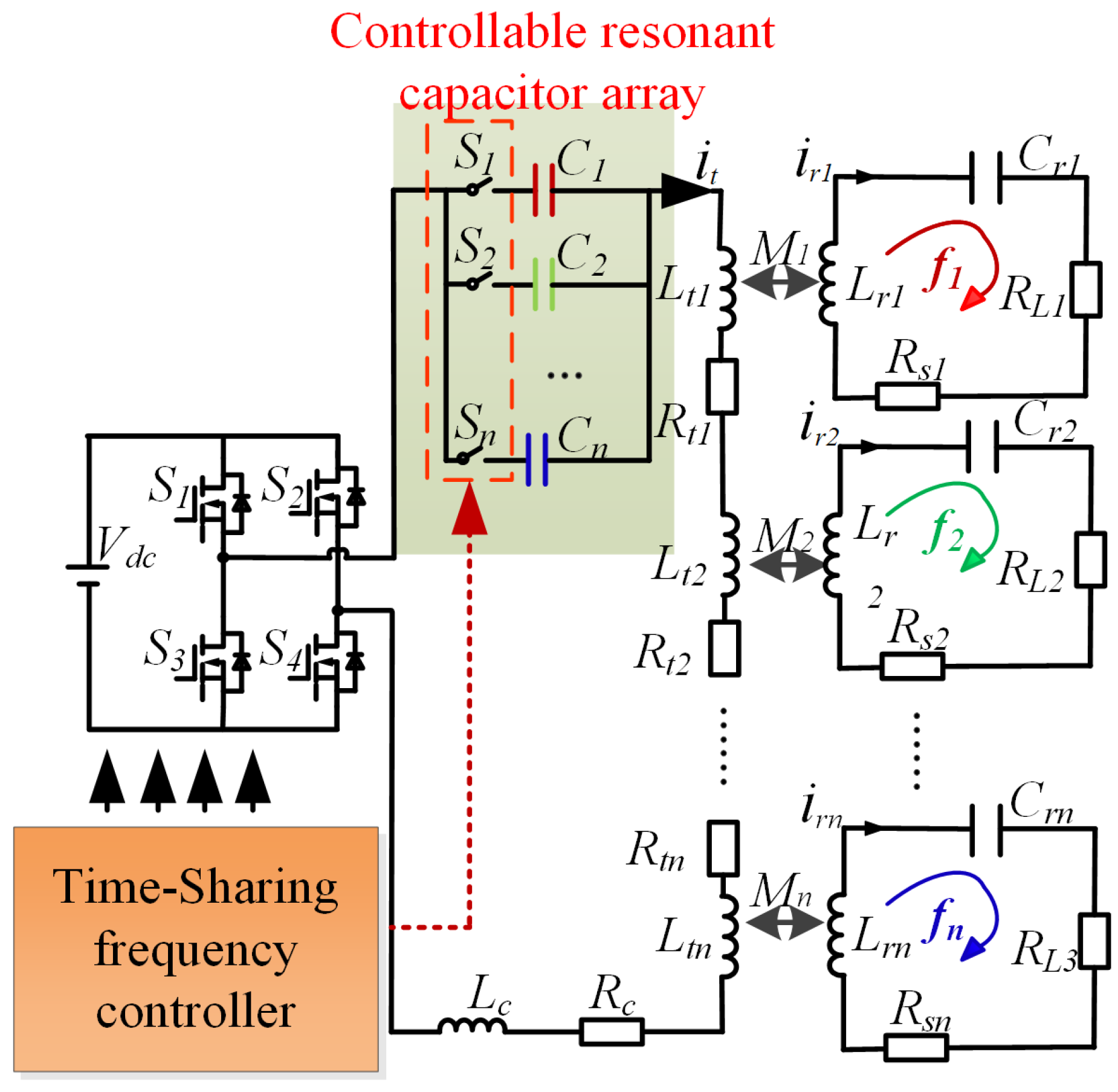
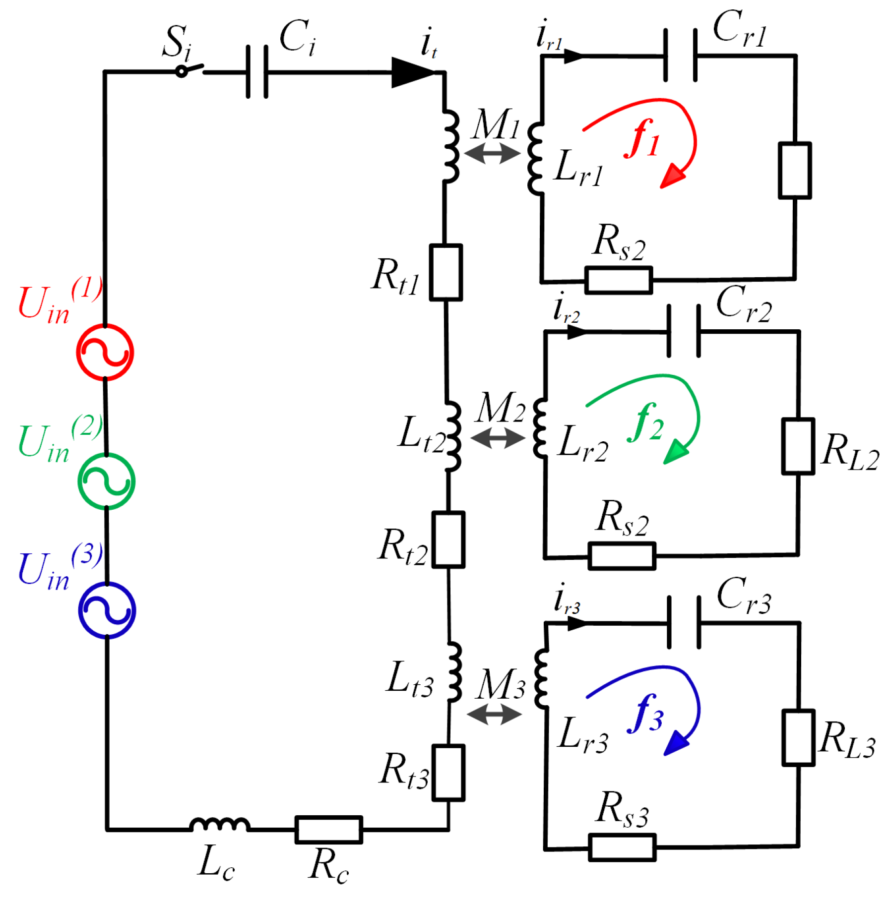
2. Circuit Model and Analysis

The schematic diagram of the proposed MFMR-ICPT system using a series–series (SS) topology controllable resonant capacitor array is shown in Figure 2. A single full-bridge inverter generates multi-frequency currents using time-sharing multiplexing technology. The controlled resonant capacitor array resonates with the inductor at varying frequencies. Each receiver is series-compensated, with its resonant compensation frequency matching that generated by the inverter. This setup ensures that only one receiver resonates with the system’s operating frequency at any given time.
As illustrated in Figure 3, the input voltage to the transmitter of the TFTR-ICPT system can be expressed as a superposition of three AC voltage sources with frequencies f 1 , f 2 , and f 3 , respectively.
Here, U i n ( 1 ) , U i n ( 2 ) , and U i n ( 3 ) are the rms values of the voltage with frequencies of f 1 , f 2 , and f 3 output by the inverter, as shown in the following:
U i n ( 1 ) = α 1 V i n 2 U i n ( 2 ) = α 2 V i n 2 U i n ( 3 ) = α 3 V i n 2
In accordance with the superposition theorem, the circuit shown in Figure 3 can be simplified to the circuit model shown in Figure 4, which reduces the system to a system of three independent ICPT circuits. When a switch is on, the other switches are off, and the capacitors start working at the same time. In addition, only one switch is operated at any given time.
Based on Kirchhoff’s law, the voltage–current matrix of the TFTR-ICPT system at a specific operating frequency f i ( i = 1 , 2 , o r 3 ) can be expressed as follows:
U i n ( i ) 0 0 0 = Z t ( i ) j ω i M 1 j ω i M 2 j ω i M 3 j ω i M 1 Z ( r 1 ) ( i ) 0 0 j ω i M 2 0 Z ( r 2 ) ( i ) 0 j ω i M 3 0 0 Z ( r 3 ) ( i ) I t ( i ) I r 1 ( i ) I r 2 ( i ) I r 3 ( i )
where ω i is the angular frequency; I t ( i ) is the current in the transmitter; and I r 1 ( i ) , I r 2 ( i ) , and I r 3 ( i ) are the currents in the three receivers. M 1 , M 2 , and M 3 are the mutual inductance between the primary and secondary sides. Z t ( i ) is the impedance of the transmitter. Z r 1 ( i ) , Z r 2 ( i ) , and Z r 3 ( i ) are the impedances of the receivers. The impedances are expressed as follows:
Z t ( i ) = R c + R t 1 + R t 2 + R t 3 + j ω i L t 1 + j ω i L t 2 + j ω i L t 3 + j ω i L c + 1 / j ω i C i Z r 1 ( i ) = R s 1 + R L 1 + j ω i L r 1 + 1 / j ω i C r 1 Z r 2 ( i ) = R s 2 + R L 2 + j ω i L r 2 + 1 / j ω i C r 2 Z r 3 ( i ) = R s 3 + R L 3 + j ω i L r 3 + 1 / j ω i C r 3
where L c is the inductance of the cable; L t 1 , L t 2 , and L t 3 are the inductance of the transmitting end of each coupled magnetic ring; L r 1 , L r 2 , and L r 3 are the inductance of the receiving ends of each coupled magnetic ring; C i is the series compensation capacitor of the transmitter; C r 1 , C r 2 , and C r 3 are the series compensation capacitors of the three receivers’ series compensation capacitors; R c is the parasitic resistance of the cable; R t 1 , R t 2 , and R t 3 are the parasitic resistance of the transmitting end coupled magnetic ring; R s 1 , R s 2 , and R s 3 are the parasitic resistance of the receiving end coupled magnetic ring; and R L 1 , R L 2 , and R L 3 are the three load resistors. The series compensation capacitors of the system are related to its operating frequency, and the relationship is as follows:
ω i C i = 1 ω i ( L c + L t 1 + L t 2 + L t 3 ) ω 1 C r 1 = 1 ω 1 L r 1 ω 2 C r 2 = 1 ω 2 L r 2 ω 3 C r 3 = 1 ω 3 L r 3
According to the above derivation, the current of the transmitter and the currents of the three receivers can be given as
I t ( i ) = U i n ( i ) Z i n ( i ) I r 1 ( i ) = j ω i M 1 U i n ( i ) Z r 1 ( i ) Z i n ( i ) I r 2 ( i ) = j ω i M 2 U i n ( i ) Z r 2 ( i ) Z i n ( i ) I r 3 ( i ) = j ω i M 3 U i n ( i ) Z r 3 ( i ) Z i n ( i )
From this, the input impedance of the system can be expressed as follows:
Z i n ( i ) = U i n ( i ) I t ( i ) = Z t ( i ) + ω i 2 ( M 3 2 Z r 1 ( i ) Z r 2 ( i ) + M 2 2 Z r 1 ( i ) Z r 3 ( i ) + M 1 2 Z r 2 ( i ) Z r 3 ( i ) ) Z r 1 ( i ) Z r 2 ( i ) Z r 3 ( i )
Following this, the output power of each load can be calculated as follows:
P o 1 ( i ) = | I r 1 ( i ) | 2 R L 1 = | U i n ( i ) ( j ω i M 1 ) Z i n ( i ) Z r 1 ( i ) | 2 R L 1 P o 2 ( i ) = | I r 2 ( i ) | 2 R L 2 = | U i n ( i ) ( j ω i M 2 ) Z i n ( i ) Z r 2 ( i ) | 2 R L 2 P o 3 ( i ) = | I r 3 ( i ) | 2 R L 3 = | U i n ( i ) ( j ω i M 3 ) Z i n ( i ) Z r 3 ( i ) | 2 R L 3
From Equation (7), it can be seen that the output power of the three loads ( P o 1 ( i ) , P o 2 ( i ) , and P o 3 ( i ) ) is mainly affected by the input voltage amplitude, the mutual inductance of the coupled magnetic ring, and the loop impedance. The effect of cross-coupling due to its inductive leakage field can be neglected because the distance between the coupling nodes under the cable system structure is far enough. In accordance with the superposition theorem, the total output power of the load can be expressed as follows:
P o 1 = P o 1 ( 1 ) + P o 1 ( 2 ) + P o 1 ( 3 ) P o 2 = P o 2 ( 1 ) + P o 2 ( 2 ) + P o 2 ( 3 ) P o 3 = P o 3 ( 1 ) + P o 3 ( 2 ) + P o 3 ( 3 )
where P o 1 , P o 2 , and P o 3 represent the total output power of receiver circuit 1, receiver circuit 2, and receiver circuit 3, respectively. The total efficiency of the system can be expressed as
η s y s = P o 1 + P o 2 + P o 3 P i n
where P i n = P o 1 + P o 2 + P o 3 + P l o s s , P l o s s is the total power of the system loss, including inverter loss, coupler loss, compensation network loss and line loss, and so on. The preceding theoretical analysis indicates that the system’s transmission characteristics are closely tied to its frequency, input voltage, and compensation structure. Thus, load power adjustment depends on the system frequency and input voltage. This paper provides a comprehensive analysis of the power transmission characteristics of a TFTR-ICPT system and proposes a TSFC strategy to enable adjustable load power regulation.

3. Analysis of Time-Sharing MFMR-ICPT System

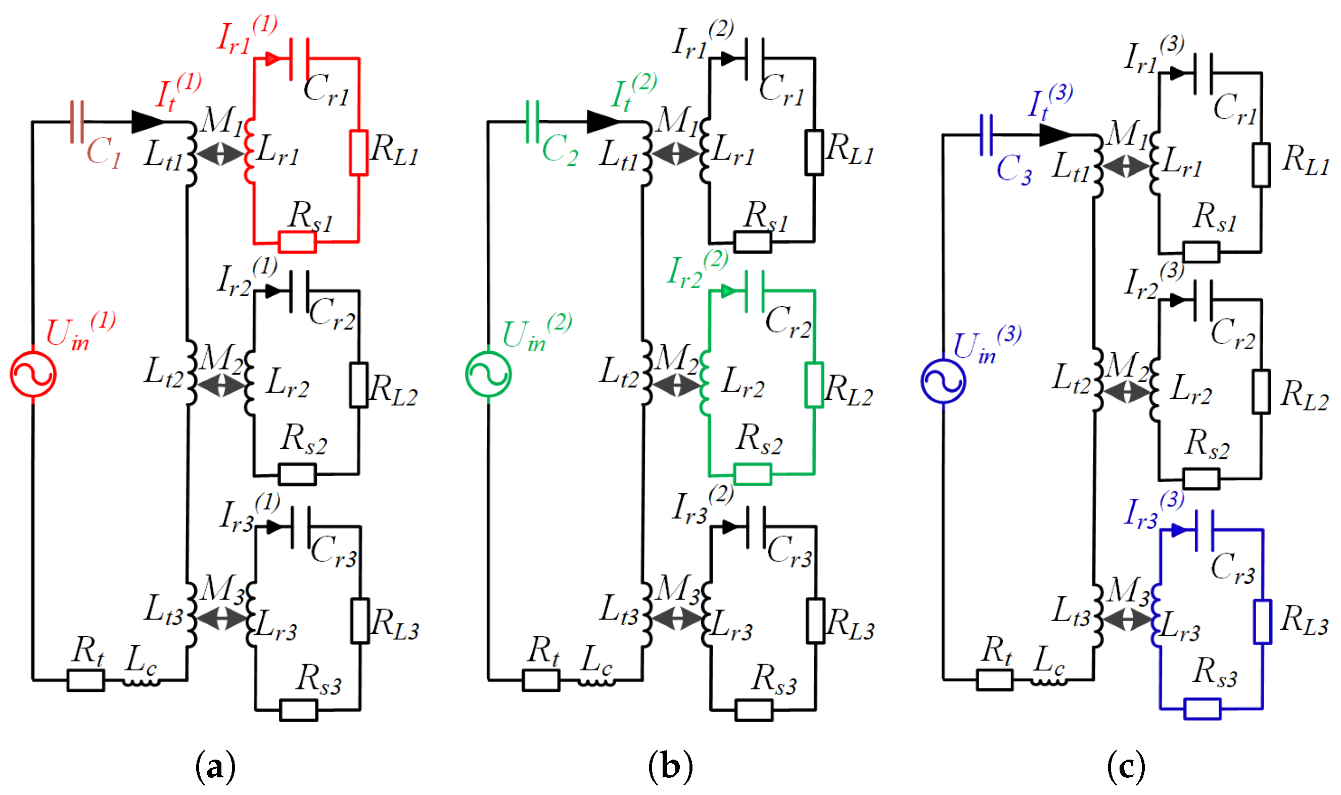
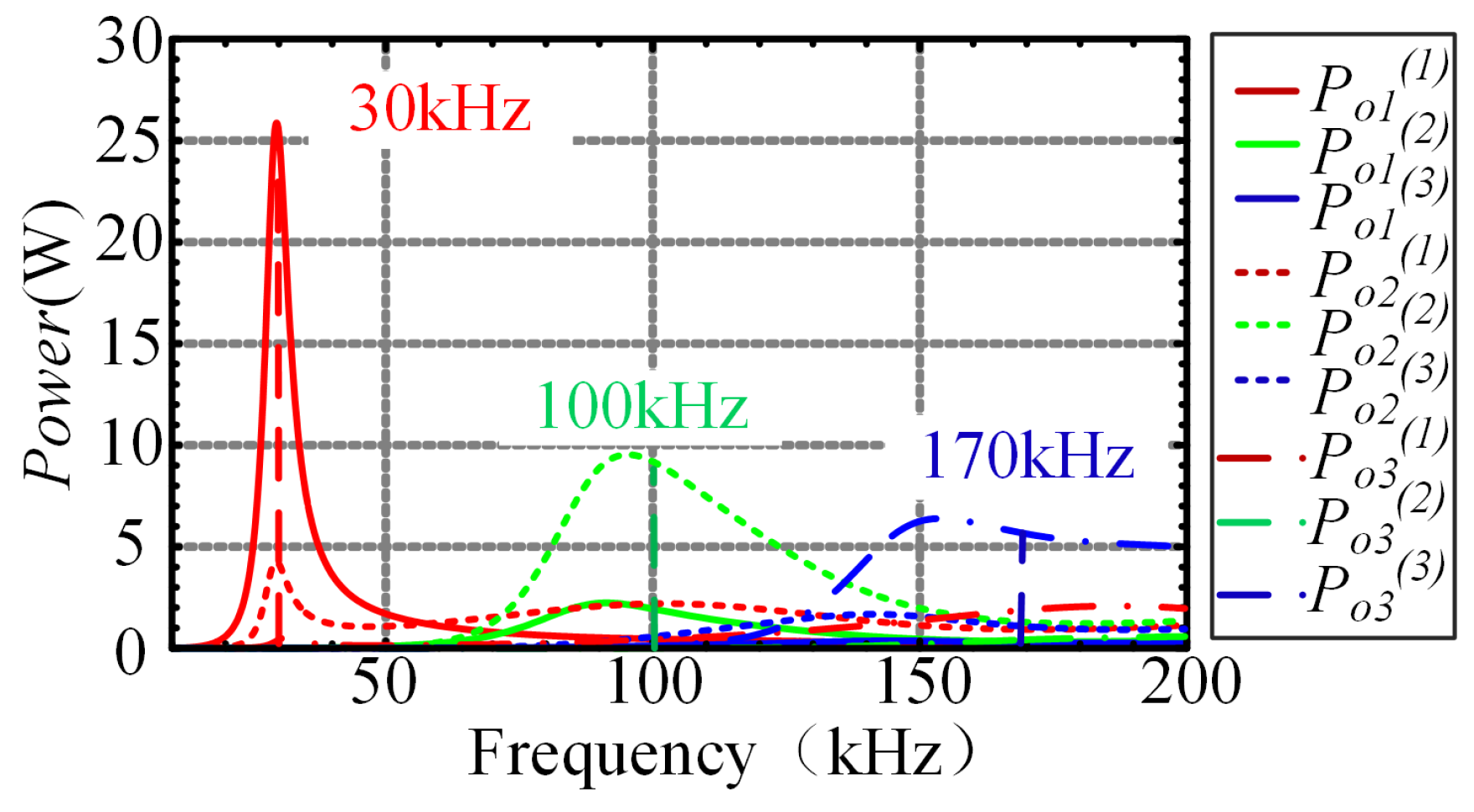
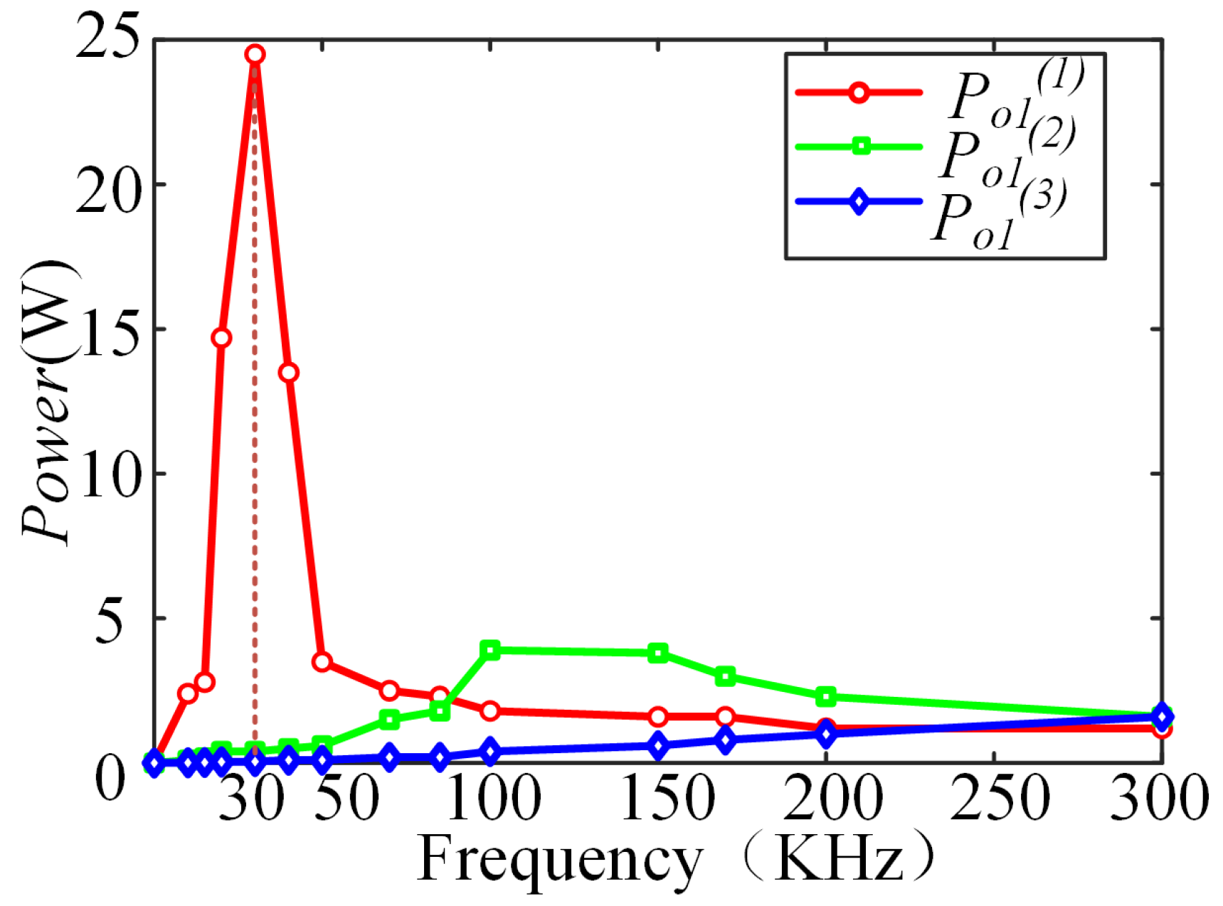
3.1. Analysis of Power Decoupling Transmission

From the above analysis of the transmission characteristics of the system, it can be seen that the output power and efficiency of each receiver circuit are not only closely related to the parameters of the system itself, but are also affected by other frequency interference. It is therefore necessary to analyze the decoupled power transfer of the system in order to reduce the cross-coupling of each receiver circuit and to achieve the power distribution of each load. Considering the TFTR-ICPT system shown in Figure 4, the inter-frequency interference to Load 1 is analyzed by transmitting energy from the supply U i n to Load 1 at different frequencies.
(1)
U i n ( 2 ) = U i n ( 3 ) = 0 , U i n ( 1 ) acting alone
According to (4), the current I t ( 1 ) of the primary side can be expressed as
I t ( 1 ) = U i n ( 1 ) R t + ( ω 1 M 1 ) 2 R L 1 + ( ω 1 M 2 ) 2 R L 2 + j X s 2 ( 1 ) + ( ω 1 M 3 ) 2 R L 3 + j X s 3 ( 1 )
where R t = R c + R t 1 + R t 2 + R t 3 , R L 1 = R L 1 + R s 1 , R L 2 = R L 2 + R s 2 , R L 3 = R L 3 + R s 3 .
Since the power supply U i n ( 1 ) acts alone, the receiving circuit 1 resonates. The resonance current I r 1 ( 1 ) of receiving circuit 1 is
I r 1 ( 1 ) = j ω 1 M 1 R L 1 I t ( 1 )
(2)
U i n ( 1 ) = U i n ( 3 ) = 0 , U i n ( 2 ) acting alone
In the same way, the current I t ( 2 ) of the primary side can be expressed as
I t ( 2 ) = U i n ( 2 ) R t + ( ω 2 M 2 ) 2 R L 2 + ( ω 2 M 1 ) 2 R L 1 + j X s 1 ( 2 ) + ( ω 2 M 3 ) 2 R L 3 + j X s 3 ( 2 )
Since the power supply U i n ( 2 ) acts alone, receiving circuit 2 does not resonate. The interference current I r 1 ( 2 ) of receiving circuit 1 is
I r 1 ( 2 ) = j ω 2 M 1 R L 1 + j X s 1 ( 2 ) I t ( 2 )
(3)
U i n ( 1 ) = U i n ( 2 ) = 0 , U i n ( 3 ) acting alone
The current I t ( 3 ) of the primary side can be expressed as
I t ( 3 ) = U i n ( 3 ) R t + ( ω 3 M 3 ) 2 R L 3 + ( ω 3 M 1 ) 2 R L 1 + j X s 1 ( 3 ) + ( ω 3 M 2 ) 2 R L 2 + j X s 2 ( 3 )
The interference current I r 1 ( 3 ) of receiving circuit 1 is
I r 1 ( 3 ) = j ω 3 M 1 R L 1 + j X s 1 ( 3 ) I t ( 3 )
To analyze the cross-coupling between the loads, the interference current I r 1 ( 2 ) of receiver circuit 1 and the resonance current I r 1 ( 1 ) are compared, as shown in the following:
| I r 1 ( 2 ) I r 1 ( 1 ) | = | R L 1 R L 1 + j X s 1 ( 2 ) · α 2 ω 2 α 1 ω 1 · R t + ( ω 1 M 1 ) 2 R L 1 + ( ω 1 M 2 ) 2 R L 2 + j X s 2 ( 1 ) + ( ω 1 M 3 ) 2 R L 3 + j X s 3 ( 1 ) R t + ( ω 2 M 2 ) 2 R L 2 + ( ω 2 M 1 ) 2 R L 1 + j X s 1 ( 2 ) + ( ω 2 M 3 ) 2 R L 3 + j X s 3 ( 2 ) | = m 1 + X s 1 ( 2 ) R L 1
where
m = | α 2 ω 2 α 1 ω 1 · R t + ( ω 1 M 1 ) 2 R L 1 + ( ω 1 M 2 ) 2 R L 2 + j X s 2 ( 1 ) + ( ω 1 M 3 ) 2 R L 3 + j X s 3 ( 1 ) R t + ( ω 2 M 2 ) 2 R L 2 + ( ω 2 M 1 ) 2 R L 1 + j X s 1 ( 2 ) + ( ω 2 M 3 ) 2 R L 3 + j X s 3 ( 2 ) |
In the same way, the expression for the comparison of the interference current I r 1 ( 3 ) of receiver circuit 1 and the resonance current I r 1 ( 1 ) is
| I r 1 ( 3 ) I r 1 ( 1 ) | = | R L 1 R L 1 + j X s 1 ( 3 ) · α 3 ω 3 α 1 ω 1 · R t + ( ω 1 M 1 ) 2 R L 1 + ( ω 1 M 2 ) 2 R L 2 + j X s 2 ( 1 ) + ( ω 1 M 3 ) 2 R L 3 + j X s 3 ( 1 ) R t + ( ω 3 M 3 ) 2 R L 3 + ( ω 3 M 1 ) 2 R L 1 + j X s 1 ( 3 ) + ( ω 3 M 2 ) 2 R L 2 + j X s 2 ( 3 ) | = n 1 + X s 1 ( 3 ) R L 1
where
n = | α 3 ω 3 α 1 ω 1 · R t + ( ω 1 M 1 ) 2 R L 1 + ( ω 1 M 2 ) 2 R L 2 + j X s 2 ( 1 ) + ( ω 1 M 3 ) 2 R L 3 + j X s 3 ( 1 ) R t + ( ω 3 M 3 ) 2 R L 3 + ( ω 3 M 1 ) 2 R L 1 + j X s 1 ( 3 ) + ( ω 3 M 2 ) 2 R L 2 + j X s 2 ( 3 ) |
The above analysis of the ICPT system shows that each loads’ output power consists of three superimposed frequencies. Consequently, the output power and efficiency of each receiver circuit are influenced by other frequencies. Reducing mutual interference among receiving circuits is key to achieving independent control of load output power. For example, in receiver circuit 1, Equations (16) and (18) show that increasing the receiver coils inductance and the frequency difference between receivers enhances frequency selectivity and reduces inter-frequency interference.
The frequency difference among receivers is a primary factor influencing system output power. Therefore, maintaining a sufficient frequency difference is essential. Conversely, a larger frequency difference can reduce cross-coupling, though it may also impact output power. In order to reduce the cross-coupling between the receivers, and taking into account that the optimal frequency of the ICPT system of the cable system is about 30 kHz, the power and efficiency of the system at this frequency are optimal. The three resonant frequencies of the system are determined with a frequency difference of 70 KHz as f s r 1 = 30 kHz, f s r 2 = 100 kHz, and f s r 3 = 170 kHz, respectively.
Figure 5 shows the output power versus frequency of the three receivers, obtained from Equation (7). It is evident that the resonant power of receivers is significantly higher than that of the two interfering frequencies. This demonstrates that effective power decoupling has been successfully achieved between the power channels operating at different frequencies.
In the MFMR-ICPT system, load output power directly correlates with both the operating frequency and the resonant frequency of the transmitter. Power transmission from the transmitter to the receiver is optimized when the transmitter’s resonant frequency aligns with the system’s operating frequency. This alignment enables a nearly complete transfer of input power to the corresponding receiver. Thus, directional power transmission in an MR-ICPT system can be achieved by controlling the transmitter’s resonance frequency and the system’s operating frequency. This allows for the independent regulation of the power of the loads.

3.2. Time-Sharing Control Strategy

In the TFTR-ICPT system proposed in this paper, as shown in Figure 2, the controllable resonant array consists of a time-sharing frequency controller and n capacitor branches connected in parallel. Each capacitor C i is connected in series with the switch S i , corresponding one-to-one with each receiver. Each of the three receivers has a distinct intrinsic resonant frequency, each corresponding to a transmitter’s operating frequency. Because each capacitor in the controllable resonant array has a unique resonant frequency, the system operates at different frequencies during each capacitor’s on-time, corresponding to each receiver’s intrinsic resonant frequency. Thus, by appropriately adjusting each resonant capacitor’s on-time to align with the system’s operating frequency, controlled power transmission is achieved.
Figure 6 shows the control-timing diagram of the system’s controllable resonant capacitor arrays S 1 S n versus the system input voltage, where T is the control period of the time-sharing frequency controller and Δ T i is the turn-on time of each switch. The number 0 represents a low level and the switch is OFF, and 1 represents a high level and the switch is ON.
During the turn-on time Δ T i , switch S i receives a high-level PWM signal, causing the switch to conduct and connecting the resonance capacitor C i in series with the system transmitter. Simultaneously, the inverter outputs an input voltage matching the transmitter’s resonance frequency, generating resonant current at the frequency of the i-th receiver. At this point, the i-th receiver operates in a resonant state, while the other receivers remain inactive, enabling directional power transmission to the i-th receiver.

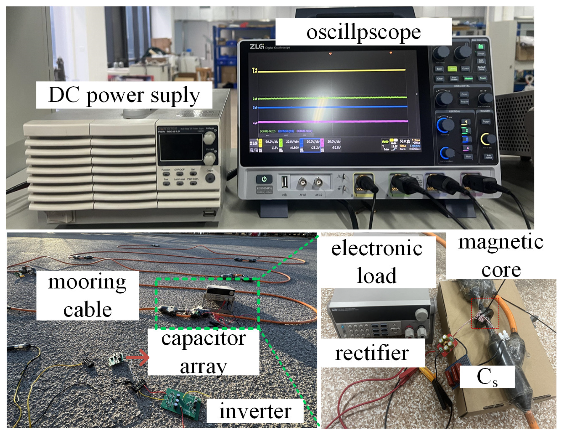
4. Experimental Verification

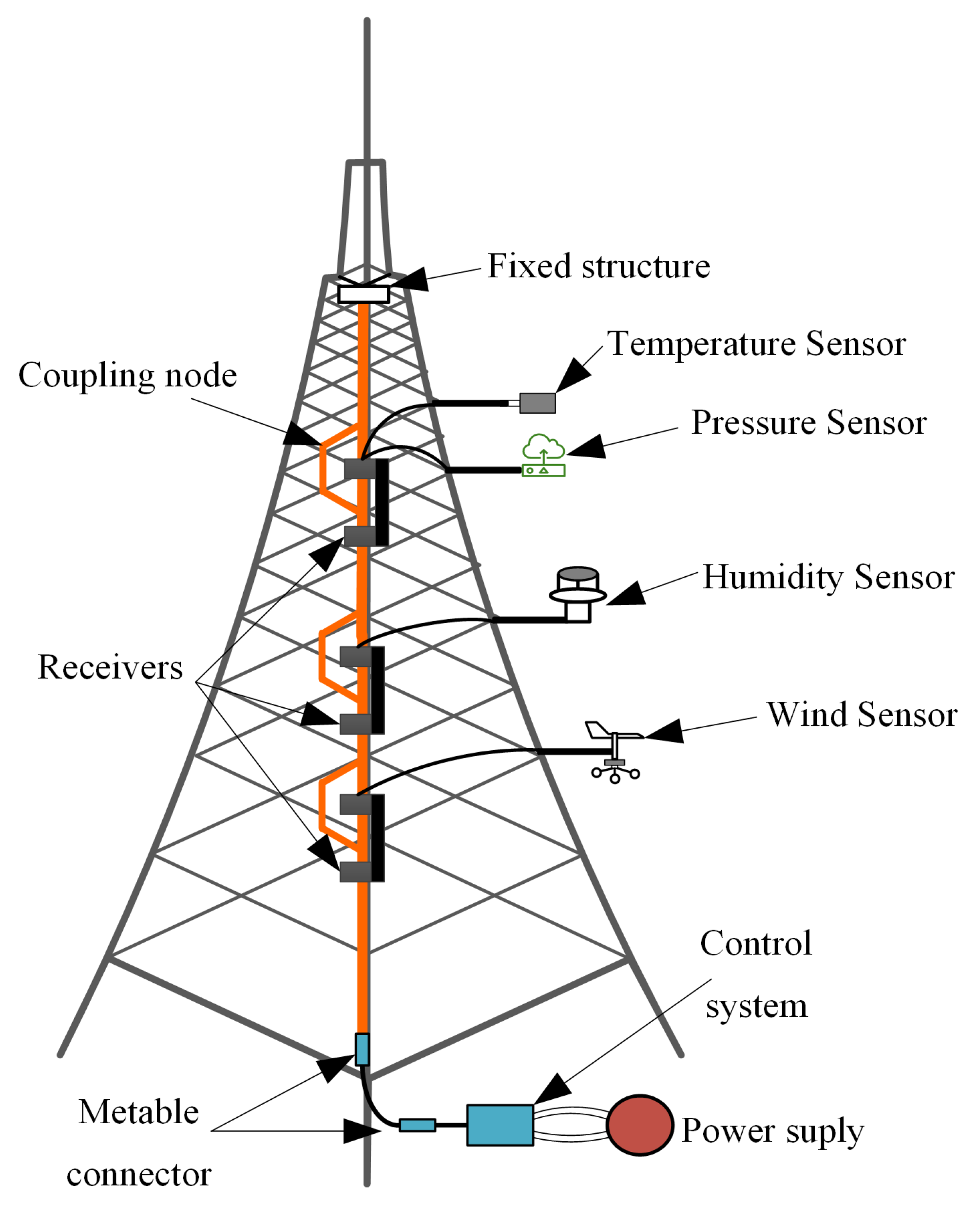
4.1. Experimental System Structure

In order to verify the feasibility and effectiveness of the independent load power control of the TFTR-ICPT system under the proposed time-sharing frequency control method, an experimental prototype, as shown in Figure 7, was built. The system parameters are shown in Table 2, and the component parameters are measured by an LCR meter TH2840B (TongHui, Changzhou, China). PSW80-40.5 (Gwinstek, New Taipei City, Taiwan, China) is utilized to provide the DC voltage. A gallium nitride GS61008P (GaN Systems, Ottawa, Canada) full-bridge inverter was used to generate AC. The magnetic ring of the ICPT is made from PC40 material, with 2 turns of Leeds wire on the primary side and 5 turns of Leeds wire on the secondary side. Four high-efficiency ultrafast diodes STTH3002 (STMicroelectronics, Geneva, Switzerland) were used in the full wave rectifier. The DC electronic load was used to replace load R L i . The MCU STM32G431KBT6 (STMicroelectronics, Geneva, Switzerland) is used to generate the PWM signal and also to control the conduction of the resonant capacitor array. The controlled resonant capacitor array consists of six MOSFET FQA38N30 (Onsemi, Phoenix, AZ, USA) and NPO capacitors. Waveforms were measured and displayed by oscilloscope ZDS5054A (ZLG, Guangzhou, China) with a differential voltage probe ZP1500D (ZLG, Guangzhou, China) and a current probe ZCP30 (ZLG, Guangzhou, China).

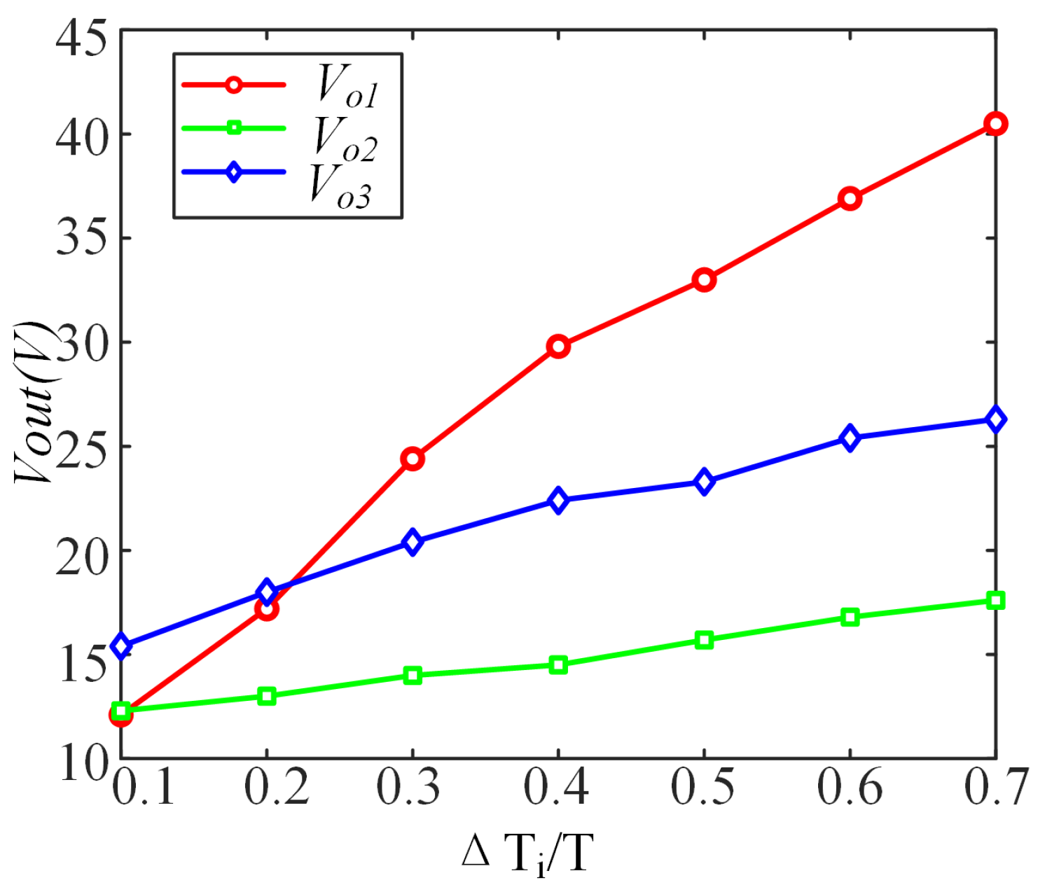
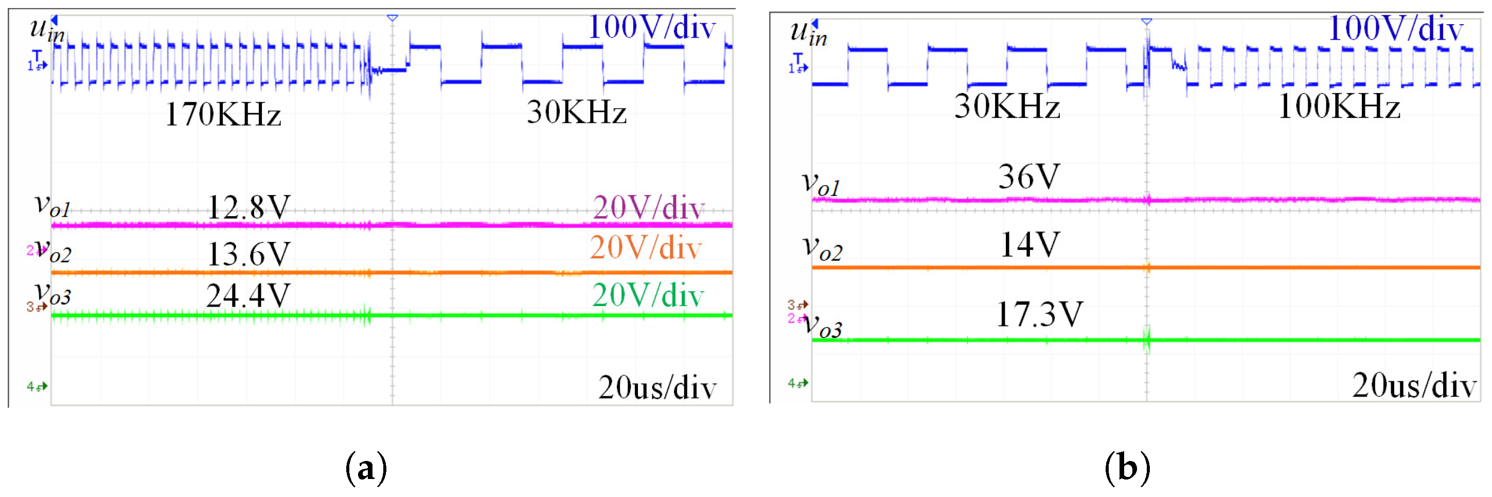
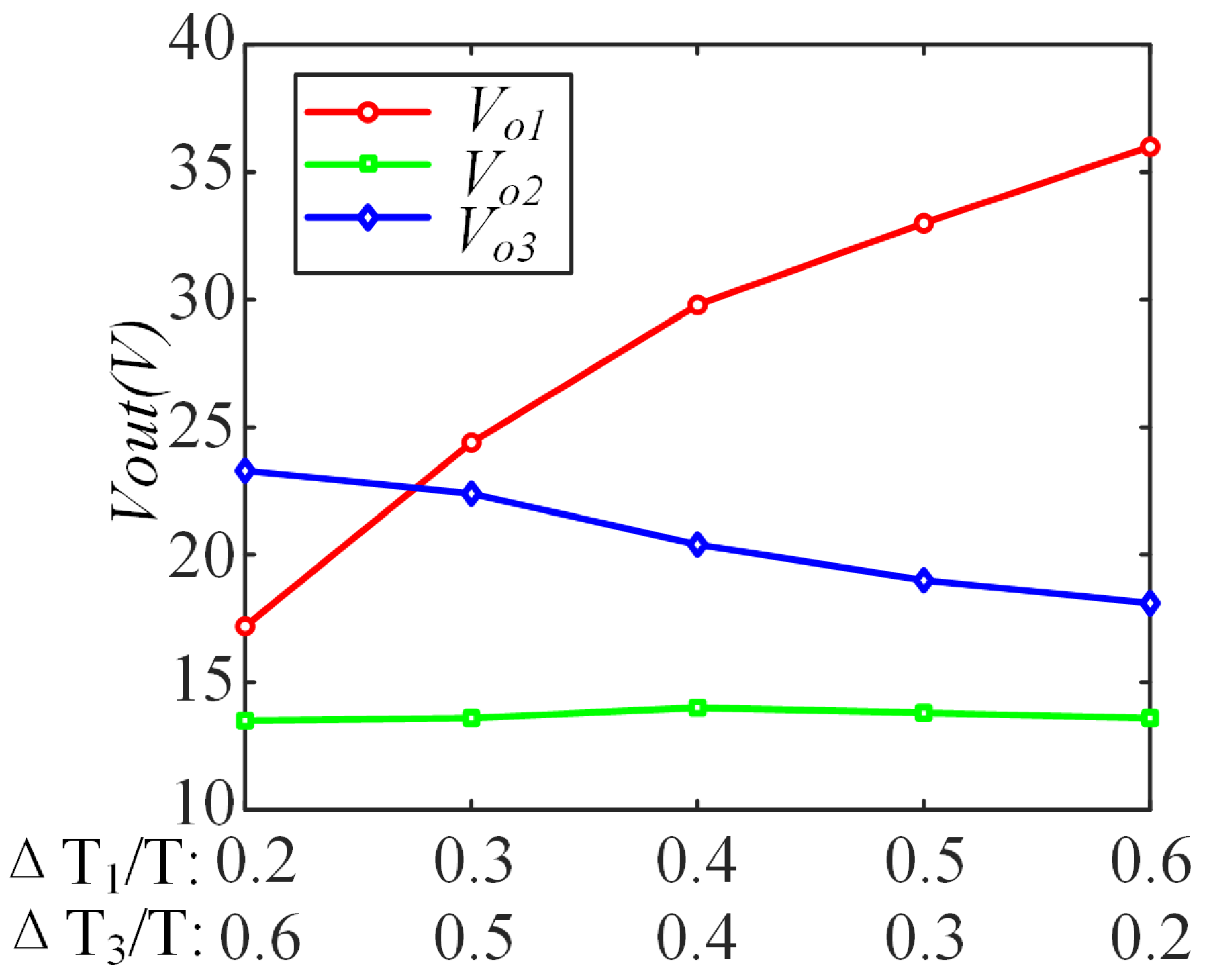
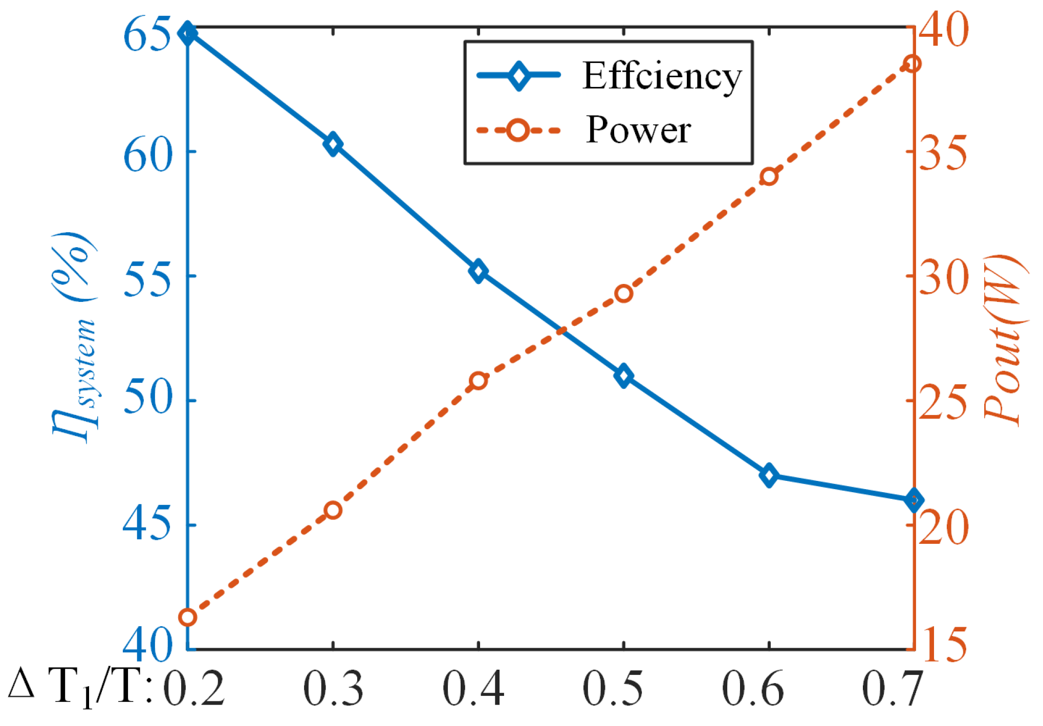
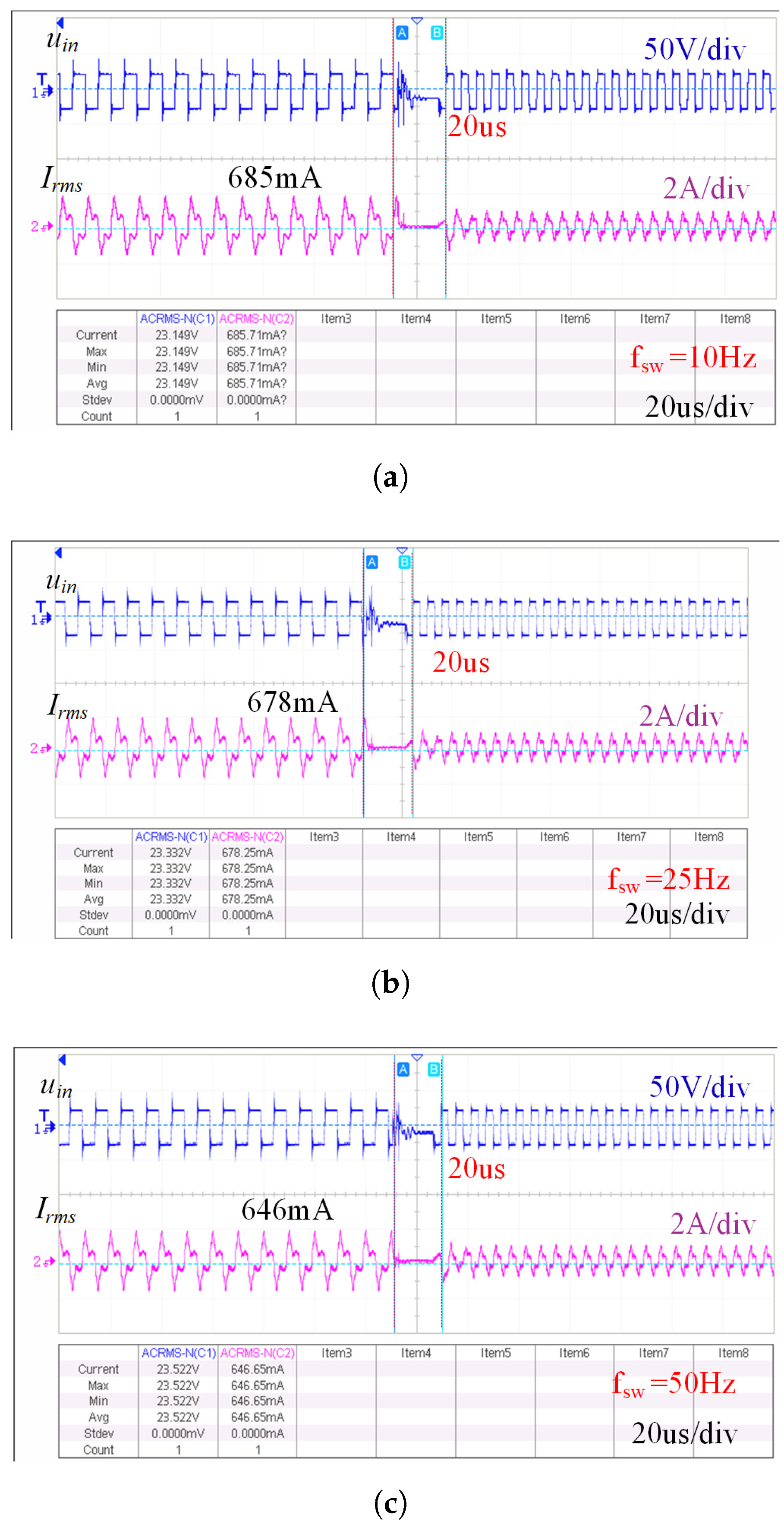
4.2. Experimental Results of Power Regulation in MFMR-ICPT Systems

First, output power regulation experiments were conducted for the TFTR-ICPT system, with each receiver having distinct resonant frequencies of 30 kHz, 100 kHz, and 170 kHz. All the electrical parameters were consistent with those in Table 1. Theoretical calculations and analyses were used to determine load resistance values that allow for the realization of higher power outputs. To verify the transmitter’s regulation effect on the receiver, the duty cycle of each frequency was adjusted incrementally from low to high in the experimental tests.
Figure 8 shows the curves of the output voltage of the three loads with the duty cycle of the input voltage of the corresponding frequency. It can be seen that the output voltage of the loads is linearly related to the duty cycle of the input voltage on-time of the corresponding resonant frequency. The smaller the input voltage duty cycle of the corresponding frequency, the smaller the output voltage. And as the duty cycle gradually increases, its output voltage gradually increases. Figure 9a,b shows the output voltage waveforms of the loads with two different duty cycles. When the duty cycle of the input voltage corresponding to load 1 is reduced from 60% to 20%, the duty cycle of the input voltage corresponding to load 2 is increased from 20% to 40%, and the duty cycle of the input voltage corresponding to load 3 is increased from 20% to 40%. As can be seen from Figure 8, the output voltage of the load changes as the duty cycle of the corresponding input voltage changes, and the output voltages of the three loads change from 36.9 V, 13.4 V, and 18.1 V to 18.3 V, 14.5 V, and 22.3 V, respectively.
Second, to verify the power decoupling characteristic of the system, experiments were conducted by changing the system’s operating frequency and the resonance compensation capacitor, and the output power of receiver 1 was tested at three different resonance compensation capacitor frequencies. The experimental results are shown in Figure 10, where the output power of receiver 1 versus the system operating frequency curve is basically consistent with the curve calculated in the previous section. Therefore, it can be proved that the system’s power decoupling has been achieved.
In addition, to verify independent power regulation performance, two sets of experiments were conducted, keeping Δ T 2 at 30% while varying Δ T 1 and Δ T 3 ; Figure 11a,b shows the inverter output waveforms and load voltage waveforms as the duty cycle varies. When Δ T 1 increases and Δ T 3 decreases while Δ T 2 remains constant, V o 1 and V o 3 vary from 12.8 V and 24.4 V to 36 V and 17.3 V, respectively, with V o 2 remaining steady at 14 V. This demonstrates that load power can be regulated independently.
In order to further verify the power independent regulation function of the TFTR-ICPT system, several sets of experiments were designed to ensure that the duty cycle of the input voltage corresponding to receiver 2 remained unchanged, and the duty cycles of the input voltages corresponding to the other two receivers were changed, respectively. The output voltages of the three loads were compared, and the experimental results are shown in Figure 12. As shown in Figure 12, with the gradual change of Δ T 1 and Δ T 3 , their corresponding V o 1 and V o 3 also change. However, with Δ T 2 held constant, V o 2 also remains stable. Thus, by adjusting the duty cycle of the input voltage at different frequencies within a specific range, load power can be independently adjusted to meet various sensor power requirements.
Finally, to verify system performance under load switching, experiments were conducted with the input voltage duty cycle Δ T 1 : Δ T 2 : Δ T 3 = 2:4:4. Under the condition that the resistance of two loads remains constant while the resistance of the third load is varied, multiple sets of experiments were conducted, and the results are presented in Table 3. It can be seen that when the load of a certain frequency changes, the load output of the other frequencies is basically unchanged. When the load R L 3 is switched from 70 Ω to 120 Ω while keeping R L 1 and R L 2 constant, Figure 13 shows that V o 3 increases with resistance, while V o 1 and V o 2 remain stable. The experiment verifies the independence and switchability of the loads of the TFTR-ICPT system, enhancing system stability and safety.
The above three experiments demonstrate that the MFMR-ICPT system, operated under a multi-frequency time-sharing control strategy, is capable of regulating the independent load power by modifying the duty cycles of input voltages at different frequencies. Moreover, switching one load does not affect the output power of the other two loads. By regulating the duty cycle of each frequency input voltage, the system meets the varying power requirements of the three loads, enabling simultaneous charging of multiple devices with different needs.
Experimental results of the output power and system efficiency are shown in Figure 14. When the duty cycle Δ T 1 is varied from 20% to 70%, the system efficiency range is 46–64.8% and the output power range is 16.3–38.7 W. As the percentage of input voltage α 1 increases, system efficiency gradually decreases while output power increases.
Furthermore, the MFMR-ICPT system operates on a meteorological gradient tower, and external environmental factors are subject to change over time, which may result in alterations to the load. As demonstrated in Table 3 and the accompanying analyses, it can be deduced that when a specific load is altered, the power of the corresponding load is subject to change, while the power of the remaining loads remains relatively unimpacted. Consequently, within the framework of the MFMR-ICPT system utilizing the TSFC method, each load is deemed to be independent. This attribute ensures the stability of the cable system within the MFMR-ICPT system on the tower.
Further, the MFMR-ICPT system with the TSFC strategy necessitates multi-frequency switching, a process that is known to result in certain switching losses. The switching frequency f s w was modified from 10 to 50 Hz, while the duty cycle Δ T 1 : Δ T 2 : Δ T 3 = 2:4:4. The waveforms of the output voltage and current of the inverter during frequency switching are depicted in Figure 15. It can be seen that with the gradual increase of f s w , the output current of the inverter will have a decreasing trend, and the relationship between the inverter efficiency η i n v and the switching frequency f s w is found through the efficiency test, as shown in Table 4. It has been demonstrated that the system exhibits switching loss; therefore, the selection of an optimal switching frequency is imperative in practical applications. However, the system’s frequency switching speed is faster, and the waveforms before and after switching are more stable.

4.3. Comparison with References

As outlined in the preceding discussion, the extant MFMR-WPT systems are characterized by a range of representative papers, which are then selected and compared with the system proposed in this paper. The results of this comparison are presented in Table 5.
In Table 5, the existing technologies are compared from five aspects: number of inverters, characteristics of multi-frequency generation method, cross-interference, power distribution, and dc–dc efficiency.
In [19], multiple inverters are controlled in parallel to generate multi-frequency currents with decoupled control of each frequency component, but it brings a larger system volume. In [20], multiple frequency power transmission channels are generated through the fundamental and third harmonic, but independent regulation of load power is not possible. In [21], the HSPWM method is employed to generate multi-frequency superimposed currents, but the high-carrier frequency has a detrimental effect on the system’s efficiency. In [22], the delta–sigma modulation method has been demonstrated to possess the capability to regulate the load power independently. However, this method frequently necessitates online calculations of the load and is challenging to implement. In [25], the application of time-sharing techniques achieves power channel transmission decoupling, but cross-coupling between its loads still exists.
Compared with the above-mentioned technologies, the proposed system achieves multi-frequency power output and independent regulation of load power. Compared to the system with multiple inverters connected in parallel, the system structure is simpler. Compared with the single inverter approach via multi-frequency modulation, the system does not require complex online calculations and achieves decoupled transmission of multiple power channels. Overall, this work has great advantages in cost-effectiveness, simplicity, feasibility, and effectiveness of independent control of load power. In addition, the cable system MFMR-ICPT system has high engineering value when applied to powering equipment on meteorological gradient towers.

5. Conclusions

In this article, a TSFC method was proposed from a new perspective to achieve independent load power regulation in multi-receiver ICPT systems. First, the TFTR-ICPT system was modeled as an example, and its power transmission characteristics were analyzed in detail to reduce cross-interference between different frequency channels. Additionally, the TSFC strategy allows independent load power control by adjusting the duty cycle of the input voltage at different frequencies. The system remains stable and controllable during load switching. Finally, experiments validate the theoretical analysis and confirm the feasibility of the proposed method. Experimental data show that the TR-TF-ICPT system under time-sharing control can achieve a total power output of approximately 38.7 W with an efficiency of 64.8%.
However, the proposed system still has some shortcomings, which need to be further studied in the future.
(1)
The efficiency of the cable-based MFMR-ICPT system is lower compared to the other ICPT systems, at 64.8%. On the one hand, the parasitic resistance of the tethered cable itself affects the system efficiency due to the specificity of the cable structure; on the other hand, with the power transfer using the TSFC strategy, the system’s controllable resonant capacitor arrays have to maintain high switching frequencies, which increases the switching losses. Therefore, the resonance compensation topology should be optimized for the particularities of the tethered cable structure, and methods to reduce the switching losses should be investigated to further improve the efficiency of the system. A longer-term plan is to design a real-time power distribution control strategy for the MFMR-ICPT and a closed-loop control method to increase the robustness of the system.
(2)
The MFMR-ICPT system, which employs the TSFC strategy, also exhibits certain deficiencies in a practical application. In accordance with the time-sharing strategy, it is not possible for the system to charge multiple loads concurrently, despite the fact that the switching speed is very fast. Furthermore, switching delays and losses are still present. So, the switching speed should be studied for the TSFC strategy to dynamically meet the needs of loads in the future.

Author Contributions

Methodology, S.P., G.W., J.X. and J.P.; Writing—original draft, G.W., S.P. and J.X.; Writing—review and editing, G.W., S.P. and J.X.; Project administration, J.X., Y.L., Y.Y. and H.L.; Funding acquisition, J.X. and H.L. All authors have read and agreed to the published version of the manuscript.

Funding

This work was supported in part by the National Science Foundation of China under Grant 62203324, the Young Elite Scientist Sponsorship Program by Cast under Grant YESS20230630, the China Postdoctoral Science Foundation under Grant 2024T170637 and 2023M732611, and in part by the Natural Science Foundation of Shandong Province under Grant ZR2022MF336.

Data Availability Statement

Data are unavailable due to privacy.

Acknowledgments

Thank you to Shui Pang, Jiayi Xu, Jianguo Pan, Hongyu Li, Yu Liu, and Yuhang Yang for their guidance in writing and revising this paper.

Conflicts of Interest

The authors declare no conflicts of interest.

References

  1. Zhang, Y.; Guo, X.; Zhao, Q.; Zhao, Z.; Kang, S. Research status and thinking of atmospheric duct. Chin. J. Radio Sci. 2020, 35, 813–831. [Google Scholar] [CrossRef]
  2. Zhao, X.; Wang, D.; Huang, S.; Huang, K.; Chen, J. Statistical estimations of atmospheric duct over the South China Sea and the tropical eastern Indian Ocean. Chin. Sci. Bull. 2013, 58, 2794–2797. [Google Scholar] [CrossRef]
  3. Shi, Y.; Zhang, Q.; Wang, S.; Yang, K.; Yang, Y.; Yan, X.; Ma, Y. A comprehensive study on maximum wavelength of electromagnetic propagation in different evaporation ducts. IEEE Access 2019, 7, 82308–82319. [Google Scholar] [CrossRef]
  4. Zhang, Z.; Pang, H.; Georgiadis, A.; Cecati, C. Wireless power transfer—An overview. IEEE Trans. Ind. Electron. 2018, 66, 1044–1058. [Google Scholar] [CrossRef]
  5. Zhang, Z.; Ai, W.; Liang, Z.; Wang, J. Topology-reconfigurable capacitor matrix for encrypted dynamic wireless charging of electric vehicles. IEEE Trans. Veh. Technol. 2018, 67, 9284–9293. [Google Scholar] [CrossRef]
  6. Liu, J.; Li, Y.; Liu, S.; Hu, J.; He, Z. A Wide Output Voltage Range and High Efficiency Dual-Channel WPT System Employing Multimode Control Strategy. IEEE Trans. Ind. Electron. 2024, 71, 12075–12085. [Google Scholar] [CrossRef]
  7. Ahn, D.; Hong, S. Wireless power transmission with self-regulated output voltage for biomedical implant. IEEE Trans. Ind. Electron. 2013, 61, 2225–2235. [Google Scholar] [CrossRef]
  8. Yan, Z.; Song, B.; Zhang, Y.; Zhang, K.; Mao, Z.; Hu, Y. A rotation-free wireless power transfer system with stable output power and efficiency for autonomous underwater vehicles. IEEE Trans. Power Electron. 2018, 34, 4005–4008. [Google Scholar] [CrossRef]
  9. Cui, S.; Zhang, J.; Bie, Z.; Song, K.; Zhu, C. A novel arc-shaped lightweight magnetic coupler for AUV wireless power transfer. IEEE Trans. Ind. Appl. 2021, 58, 1315–1329. [Google Scholar]
  10. Gu, Y.; Wang, J.; Liang, Z.; Wu, Y.; Cecati, C.; Zhang, Z. Single-transmitter multiple-pickup wireless power transfer: Advantages, challenges, and corresponding technical solutions. IEEE Ind. Electron. Mag. 2020, 14, 123–135. [Google Scholar] [CrossRef]
  11. Xu, J.; Li, X.; Xie, Z.; Fu, C.; Du, R. Design and Analysis of Inductively Coupled Power Transfer System on Mooring Buoy With Double Ultracapacitor Chargers Using Indirect Control. IEEE Trans. Ind. Electron. 2020, 67, 4836–4845. [Google Scholar] [CrossRef]
  12. Xu, J.; Li, X.; Xie, Z.; Zhang, H.; Wu, T.; Fang, C. Research on a Multiple-Receiver Inductively Coupled Power Transfer System for Mooring Buoy Applications. Energies 2017, 10, 519. [Google Scholar] [CrossRef]
  13. Cui, X.; Xu, J.; Pang, S.; Li, X.; Li, H. Design and Implementation of Inductively Coupled Power and Data Transmission for Buoy Systems. Energies 2023, 16, 4417. [Google Scholar] [CrossRef]
  14. Qi, C.; Miao, H.; Lang, Z.; Chen, X. A generalized methodology to generate, amplify and compensate multi-frequency power for a single-inverter-based MF-MR-S-WPT system. IEEE Access 2020, 8, 181513–181525. [Google Scholar] [CrossRef]
  15. De Souza, W.G.; Gomes, L.C.; Lannes, L.R.; Andrade, D.A. Analysis and modeling of a wireless power transmission system for multiple receivers. IEEE Lat. Am. Trans. 2021, 19, 1987–1994. [Google Scholar] [CrossRef]
  16. Fu, M.; Zhang, T.; Ma, C.; Zhu, X. Efficiency and optimal loads analysis for multiple-receiver wireless power transfer systems. IEEE Trans. Microw. Theory Tech. 2015, 63, 801–812. [Google Scholar] [CrossRef]
  17. Xie, X.; Xie, C.; Wang, J.; Li, Y.; Du, Y.; Li, L. Constant Current Output Control Based on Cross-Coupling Compensation in Multireceiver WPT System Using Active Rectifier. IEEE Trans. Transp. Electrif. 2023, 9, 1960–1972. [Google Scholar] [CrossRef]
  18. Ahn, D.; Mercier, P.P. Wireless power transfer with concurrent 200-kHz and 6.78-MHz operation in a single-transmitter device. IEEE Trans. Power Electron. 2015, 31, 5018–5029. [Google Scholar] [CrossRef]
  19. Liu, F.; Yang, Y.; Ding, Z.; Chen, X.; Kennel, R.M. A multifrequency superposition methodology to achieve high efficiency and targeted power distribution for a multiload MCR WPT system. IEEE Trans. Power Electron. 2017, 33, 9005–9016. [Google Scholar] [CrossRef]
  20. Pantic, Z.; Lee, K.; Lukic, S.M. Receivers for multifrequency wireless power transfer: Design for minimum interference. IEEE J. Emerg. Sel. Top. Power Electron. 2014, 3, 234–241. [Google Scholar] [CrossRef]
  21. Xia, C.; Wei, N.; Zhang, H.; Zhao, S.; Li, Z.; Liao, Z. Multifrequency and multiload MCR-WPT system using hybrid modulation waves SPWM control method. IEEE Trans. Power Electron. 2021, 36, 12400–12412. [Google Scholar] [CrossRef]
  22. Qi, C.; Huang, S.; Chen, X.; Wang, P. Multifrequency modulation to achieve an individual and continuous power distribution for simultaneous MR-WPT system with an inverter. IEEE Trans. Power Electron. 2021, 36, 12440–12455. [Google Scholar] [CrossRef]
  23. Pang, S.; Xu, J.; Li, H.; Ma, Q.; Li, X. Dual-frequency modulation to achieve power independent regulation for dual-load underwater wireless power connector. IEEE J. Emerg. Sel. Top. Power Electron. 2022, 11, 2377–2389. [Google Scholar] [CrossRef]
  24. Kim, Y.J.; Ha, D.; Chappell, W.J.; Irazoqui, P.P. Selective wireless power transfer for smart power distribution in a miniature-sized multiple-receiver system. IEEE Trans. Ind. Electron. 2015, 63, 1853–1862. [Google Scholar] [CrossRef]
  25. Luo, C.; Qiu, D.; Gu, W.; Zhang, B.; Chen, Y.; Xiao, W. Multiload wireless power transfer system with constant output power and efficiency. IEEE Trans. Ind. Appl. 2021, 58, 1101–1114. [Google Scholar] [CrossRef]
  26. Sun, A.; Xia, C.; Chen, Y.; Liu, Y.; Yang, Z.; Zhao, S.; Yang, Z. Multifrequency and Multiload MCR-WPT System Based on Hysteresis Current Control. IEEE Trans. Power Electron. 2024, 39, 10532–10545. [Google Scholar] [CrossRef]
  27. Wang, C.; Li, F.; Cao, Y. Dual-Frequency Dual-Type-Output Wireless Power Transfer System with Independent Adjustable Outputs. IEEE J. Emerg. Sel. Top. Power Electron. 2025. [Google Scholar] [CrossRef]
  28. Gong, Y.; Zhang, Z.; Chang, S. Single-Transmitter-Controlled Multiple-Channel Constant Current Outputs for In-Flight Wireless Charging of Drones. IEEE Trans. Ind. Electron. 2024, 71, 3606–3616. [Google Scholar] [CrossRef]
Figure 1. Structure of the ICPT system on the meteorological observation tower.
Energies 18 01389 g001
Figure 2. Structure diagram of an MFMR-ICPT system using a time-sharing frequency control strategy.
Energies 18 01389 g002
Figure 3. Equivalent circuit of the TFTR-ICPT system.
Energies 18 01389 g003
Figure 4. Simplified circuit model of a TFTR-ICPT system using the superposition method. (a) U i n ( 1 ) acting alone. (b) U i n ( 2 ) acting alone. (c) U i n ( 3 ) acting alone.
Energies 18 01389 g004
Figure 5. Curve of resonant power and interference power versus working frequency for three loads.
Energies 18 01389 g005
Figure 6. Time-sharing frequency control sequence diagram.
Energies 18 01389 g006
Figure 7. Experimental prototype of TFTR-ICPT system.
Energies 18 01389 g007
Figure 8. Output voltage versus duty cycle curves for three loads.
Energies 18 01389 g008
Figure 9. Waveforms of load output voltage at fixed duty cycle. (a) Δ T 1 : Δ T 2 : Δ T 3 = 6:2:2. (b) Δ T 1 : Δ T 2 : Δ T 3 = 2:4:4.
Energies 18 01389 g009
Figure 10. Experimental results of resonant power and interference power versus working frequency for Load 1.
Energies 18 01389 g010
Figure 11. Waveform of load output voltage with constant duty cycle Δ T 2 . (a) Δ T 1 : Δ T 2 : Δ T 3 = 1:3:6. (b) Δ T 1 : Δ T 2 : Δ T 3 = 6:3:1.
Energies 18 01389 g011
Figure 12. Experiments on the variation of output voltage with duty cycle for three loads.
Energies 18 01389 g012
Figure 13. Waveforms of load output voltage before and after load switching. (a) R L 1 = R L 12 = 50 Ω , R L 3 = 70 Ω . (b) R L 1 = R L 12 = 50 Ω , R L 3 = 120 Ω .
Energies 18 01389 g013
Figure 14. Measured output power and system efficiency of the TFTR-ICPT system using TSFC method.
Energies 18 01389 g014
Figure 15. Waveforms of the output voltage and current of the inverter by using a time-sharing control strategy in a different switching frequency. (a) f s w = 10 Hz. (b) f s w = 25 Hz. (c) f s w = 50 Hz.
Energies 18 01389 g015
Table 1. Sensor power consumption.
SensorInput VoltagePower Consumption
Temperature Sensor5 V0.5 W
3D Sonic Anemometer Sensor9–30 V1.0 W
Atmospheric Pressure Sensor10–35 V8.0 W
Infrared Gas Analyzer10–30 V10.0 W
Table 2. System parameters of the experiment.
ParameterExperiment ValueUnit
DC supply V i n 36V
Frequency f i ( i = 1 , 2 , 3 ) 30/100/170kHz
Transmitting coil L t i ( i = 1 , 2 , 3 )
R t i ( i = 1 , 2 , 3 )
14.8/15.6/13.2
0.01/0.09/0.1
μ H
Ω
Compensation C i (i = 1, 2, 3)500/44.9/15.5nF
Mooring cable L c
R c
12.7
1.2
μ H
Ω
Receiving coil L r i ( i = 1 , 2 , 3 )
R s i ( i = 1 , 2 , 3 )
92/94.5/80.7
0.1/0.6/1.2
μ H
Ω
Mutual inductance M i (i = 1, 2, 3)36/36.25/30.75 μ H
Compensation C r i (i = 1, 2, 3)306/26.8/10.85nF
Loads R L i (i = 1, 2, 3)50/50/100 Ω
Table 3. System output under load change.
Load ValueOutput VoltageOutput Power
R 1 = 50 Ω , R 2 = 50 Ω , R 3 = 50 Ω V o 1 = 18.3  V
V o 2 = 14.4  V
V o 3 = 14.2  V
P o 1 = 7.0  W
P o 2 = 4.1  W
P o 3 = 4.0  W
R 1 = 10 Ω , R 2 = 50 Ω , R 3 = 50 Ω V o 1 = 5.0  V
V o 2 = 14.5  V
V o 3 = 14.7  V
P o 1 = 2.5  W
P o 2 = 4.2  W
P o 3 = 4.3  W
R 1 = 100 Ω , R 2 = 50 Ω , R 3 = 50 Ω V o 1 = 29.1  V
V o 2 = 14.6  V
V o 3 = 14.0  V
P o 1 = 8.5  W
P o 2 = 4.3  W
P o 3 = 3.9  W
R 1 = 50 Ω , R 2 = 10 Ω , R 3 = 50 Ω V o 1 = 17.8  V
V o 2 = 3.6  V
V o 3 = 13.8  V
P o 1 = 6.3  W
P o 2 = 1.2  W
P o 3 = 3.8  W
R 1 = 50 Ω , R 2 = 100 Ω , R 3 = 50 Ω V o 1 = 18.4  V
V o 2 = 21.5  V
V o 3 = 14.2  V
P o 1 = 6.7  W
P o 2 = 4.6  W
P o 3 = 4.0  W
R 1 = 50 Ω , R 2 = 50 Ω , R 3 = 10 Ω V o 1 = 18.0  V
V o 2 = 14.0  V
V o 3 = 3.3 V
P o 1 = 6.5  W
P o 2 = 3.9  W
P o 3 = 1.1 W
R 1 = 50 Ω , R 2 = 50 Ω , R 3 = 100 Ω V o 1 = 18.7  V
V o 2 = 14.5  V
V o 3 = 24.2 V
P o 1 = 7.0  W
P o 2 = 4.2  W
P o 3 = 5.9 W
Table 4. Efficiency measurement results.
f s w 10 Hz25 Hz50 Hz
η i n v 95.1%94.1%92.3%
Table 5. Comparison results with references.
ReferenceNumber
of Inverters
Multi-Frequency
Current Generation
Cross-InterferencePower DistributionEfficiency (%)
[19]SeveralMultiple inverters
and transformers
Exist(large)Uncontrollable85
 [20]OneFundamental and
harmonic
MinimumUncontrollablen/a
(Not applicable)
 [21]OneHSPWM
(with high carrier frequency)
MinimumControllable6570
[22]OneDelta–sigma modulation
(with complex calculation)
MinimumControllable84
[25]OneTime sharingExistControllable80
This workOneTime sharingAlmost eliminatedControllable64.8
Disclaimer/Publisher’s Note: The statements, opinions and data contained in all publications are solely those of the individual author(s) and contributor(s) and not of MDPI and/or the editor(s). MDPI and/or the editor(s) disclaim responsibility for any injury to people or property resulting from any ideas, methods, instructions or products referred to in the content.

