Review

Large Eddy Simulation Approaches for Trailing-Edge Heat Transfer in Gas Turbine Blades: A Review

School of Mechanical Engineering, Kookmin University, Seoul 02707, Republic of Korea
Energies 2025, 18(6), 1386; https://doi.org/10.3390/en18061386
Submission received: 27 November 2024 / Revised: 3 March 2025 / Accepted: 7 March 2025 / Published: 11 March 2025

Abstract

:
The trailing edge of gas turbine blades encounters concentrated heat loads, necessitating cooling techniques distinct from those used in mid-chord regions. Narrow cooling channels in these areas typically incorporate pin fins or dimples for internal cooling. In contrast, external cooling relies on cutback film cooling configurations, which differ significantly from mid-chord designs. Large eddy simulation (LES) has emerged as a powerful tool for investigating heat transfer in these challenging environments, capturing intricate flow phenomena and turbulence effects that Reynolds-Averaged Navier–Stokes (RANS) simulations often cannot resolve. This review synthesizes findings from 54 LES-based studies on trailing edge cooling, focusing on three key configurations: pin fin arrays, dimpled surfaces, and cutback film cooling. LES consistently demonstrated higher accuracy in predicting heat transfer and cooling effectiveness, outperforming RANS by resolving complex flow structures such as horseshoe vortices, shear layer vortices, and unique flow interactions inherent to these geometries. Furthermore, LES provided detailed turbulence statistics and local heat transfer distributions, offering critical insights for optimizing and improving predictive models. Beyond its demonstrated capabilities, this review underscores the future potential of LES in advancing shape optimization, transient flow analysis, and multi-physics simulations, including conjugate heat transfer and flow-structure interactions.

1. Introduction

The pursuit of high-efficiency gas turbines is primarily driven by environmental and economic considerations. Increased efficiency reduces fuel consumption and greenhouse gas emissions, which are critical for combating climate change and meeting stringent environmental regulations [1]. Additionally, higher efficiency translates to significant cost savings by lowering operational expenses, thereby enhancing the profitability and economic viability of power generation [2]. Advances in heat transfer, aerodynamics, and materials science have enabled these improvements, allowing turbines to operate at higher temperatures and pressures without compromising reliability.
Achieving higher efficiency in gas turbines requires several key factors: elevated turbine inlet temperature, higher pressure ratios, optimized aerodynamics, and state-of-the-art combustion systems [3]. Materials such as single-crystal superalloys and ceramic matrix composites are integral to these developments, offering exceptional durability and resistance to thermal stress in high-temperature environments [4]. Enhanced aerodynamic designs reduce energy losses, while higher pressure ratios improve combustion efficiency [5]. Among these, the most critical factor is the advancement of blade cooling techniques [6]. As illustrated in Figure 1a, methods like film cooling, internal cooling passages, and pin fins are essential for maintaining optimal blade temperatures. These strategies enable turbine blades to endure higher inlet total temperatures, thereby increasing thermal efficiency [7].
Cooling strategies for turbine blades are tailored to their location on the blade, as shown in Figure 1a [8], because each section encounters unique thermal loads, as depicted in Figure 1b [9]. The leading edge, for instance, faces the highest thermal loads due to direct exposure to high-temperature gas flows and the stagnation point. To address these conditions, film cooling and impingement cooling are employed [10]. Film cooling involves ejecting coolant through small holes to create a protective layer over the blade surface [11]. In contrast, impingement cooling directs coolant through internal holes or slots, allowing it to directly impact and cool the inner surface of the leading edge [12].
The mid-chord section is commonly modeled as a flat plate on the exterior and a square channel on the interior, making it the focus of much research. Internal convection cooling is typically employed in this area, with coolant air flowing through serpentine channels or ribbed passages inside the blade to absorb heat [13]. A significant heat load is also applied to the pressure side of the trailing edge (see Figure 1b). Accordingly, the trailing edge of turbine blades requires specialized cooling techniques due to its thin structure, high-temperature gradients, and the need to maintain aerodynamic efficiency [14].
To address these challenges, various cooling strategies are used. Trailing edge slots expel coolant through narrow openings, creating a cooling film over the surface [15]. A rib turbulator increases the blockage ratio compared to the mid-chord, resulting in a substantial pressure drop [16]. An alternative solution is the use of dimples, which enhance convective heat transfer by disrupting boundary layer flow [17]. Pin fin arrays, consisting of small cylindrical pins within cooling channels, enhance convective heat transfer by increasing the surface area [18]. These methods collectively ensure the trailing edge remains cool and structurally intact without compromising the aerodynamic characteristics of the turbine blade.
Computational fluid dynamics (CFD) offers several advantages in gas turbine cooling design. It provides detailed insights into fluid flow and heat transfer phenomena within turbines, allowing engineers to optimize cooling strategies without relying on extensive physical prototypes [19]. It enables iterative design improvements by quickly evaluating multiple configurations and operating conditions, improving the reliability and efficiency of turbine cooling systems. Additionally, CFD can identify potential issues such as thermal hotspots, which may contribute to stress concentrations when coupled with structural analysis. In combination with Computational Structural Mechanics (CSM) or fluid–structure interaction (FSI) simulations, CFD results can help mitigate risks and enhance overall turbine performance [20].
However, using CFD for turbine cooling design presents challenges. High-fidelity simulations, such as large eddy simulation (LES) or direct numerical simulation (DNS), are computationally demanding, requiring significant processing power and time to resolve complex flow and heat transfer interactions accurately. In contrast, Reynolds-Averaged Navier–Stokes (RANS) models, though less detailed, are preferred for routine design and optimization due to their computational efficiency and simplicity [21]. RANS models provide steady-state or time-averaged solutions, making them suitable for industrial applications where computational resources are limited. However, RANS may struggle to accurately predict complex turbulent flows and intricate heat transfer phenomena, particularly in areas with significant flow separation or strong pressure gradients [22].
Large eddy simulation (LES) offers superior accuracy by directly resolving larger scales of turbulence and capturing unsteady, dynamic flow behaviors in detail. This makes LES particularly valuable for analyzing specific components or regions within gas turbines where precise predictions of turbulence and heat transfer are essential. However, LES is computationally intensive and complex to implement, limiting its application to component-level analysis or research and development rather than full-scale turbine simulations [23].
LES has demonstrated its accuracy in predicting film cooling effectiveness for critical external cooling regions, such as the mid-chord and leading edge regions, where RANS models tend to underpredict performance [24]. For internal cooling applications, such as ribbed turbulators, LES successfully resolved local heat transfer details that RANS struggled to capture accurately. While RANS results often vary significantly depending on the turbulence model selected, LES provides high-fidelity predictions with minimal sensitivity to sub-grid scale modeling [25].
Furthermore, LES accurately reproduces turbulence characteristics that RANS cannot resolve, offering detailed insights into heat transfer mechanisms and their interactions with free-stream flows. Unlike RANS, which relies on steady-state or time-averaged assumptions, LES captures unsteady flow dynamics, uncovering intricate heat transfer phenomena and delivering a more comprehensive understanding of fluid flow behaviors in turbine cooling applications [26].
As illustrated in Figure 1a, common cooling strategies in gas turbine blades include film cooling and ribbed channels. LES has been extensively applied to study these techniques, and this review synthesizes and compares the key findings from various LES studies in the literature [24,25]. Due to the unique geometry of the trailing edge, cooling strategies such as pin fins or dimples, and modified cooling configurations are often employed. Recently, LES studies have focused on these techniques, but a thorough review is still lacking.
For trailing-edge cooling, Du et al. [27] provided an excellent review of experimental results. Building upon their work, this paper offers a comparative analysis of LES studies on pin fin, dimple, and cutback configurations—key trailing-edge cooling methods identified in their research. These methods were chosen for their widespread use and extensive study using LES, which provides a comprehensive dataset for review. This review contributes by offering a systematic collection and chronological organization of LES studies, allowing for a clear identification of temporal and spatial trends in modeling techniques, software, and simulation conditions.
In addition, a detailed comparison of LES and RANS results from various groups is presented, focusing on commonly used validation problems to highlight the discrepancies in their predictions. The LES findings for each cooling method are then classified and reviewed by topic, providing a comprehensive assessment of the unique insights that LES has uncovered—insights often missed by RANS models. Finally, the paper discusses the potential future advancements enabled by LES techniques, emphasizing their role in advancing the understanding and application of trailing-edge cooling.

2. Large Eddy Simulation of Flow and Heat Transfer in Pin Fin Ducts

Pin fins are commonly used to enhance heat transfer in various applications by increasing surface area and intensifying turbulence. In the trailing edge of gas turbines, where the height-to-diameter ratios are typically low, research has increasingly focused on optimizing factors such as pin fin shape, arrangement, aspect ratio, and rotation. This research has progressed from single- to multi-row configurations and from static to rotating conditions [28]. As shown in Figure 2a, complex secondary flows around pin fins—driven by vortex structures like the horseshoe vortex—improve heat transfer by enhancing mixing and shear between the mainstream and boundary layer fluids [29]. Figure 2b shows that the highest heat transfer occurs at the front edge of the pin fin, where the horseshoe vortex thins the boundary layer. Additionally, variations in pin fin cross-section shape affect wake development and heat transfer distribution [30].
Since 2004, numerous LES studies on pin-finned ducts have been published. This review examines 16 such papers from the open literature, with key information summarized in Table 1.
The studies in Table 1 are grouped by institution and listed in chronological order. While most studies utilize LES, some adopt hybrid approaches such as DES or SBES. Various SGS models, including WALE, Smagorinsky, and dynamic models, have been employed, with reports indicating that these models have minimal impact on the overall results [34]. In the early years, in-house codes were predominantly used, but there has been an increasing trend toward the adoption of commercial codes in recent years. The studies primarily focus on pin fin spacing (p) set at 2.5 times the pin diameter (dp), with channel heights (H) typically being twice the pin diameter.Many studies also compare LES with RANS or hybrid LES methods, emphasizing detailed flow structures captured by LES and the thermal performance of pin-finned cooling channels. More recent studies explore geometries that resemble gas turbine trailing edges, film cooling analysis, and conjugate heat transfer, including conduction. These topics are organized and discussed by category in the following sections.

2.1. Comparative Study of Modeling Approaches (RANS, LES, Hybrid)

Since the introduction of LES for pin-finned channels, numerous studies have focused on comparing different modeling approaches, including LES, RANS, unsteady RANS (URANS), and hybrid methods, for flow and heat transfer analysis. Carnevale et al. [33] critically assessed RANS, URANS, and LES for predicting flow and heat transfer in pin fin cooling channels, typical of turbomachinery. While RANS is computationally efficient (requiring 400 CPU hours), LES and URANS (requiring 20,000 CPU hours each) offer higher accuracy, particularly in capturing complex flow structures. However, RANS struggles to accurately predict separation regions that significantly affect heat transfer.
Several studies have explored hybrid RANS/LES methods or very large eddy simulation (VLES) to balance computational cost with accuracy. Kim and Chang [40] found that two hybrid models, detached eddy simulation (DES) and stress blended eddy simulation (SBES), outperformed URANS for staggered pin fin arrays at Re = 10,000, with SBES effectively capturing 3D vortex structures. Wan et al. [42] applied VLES to simulate flow and heat transfer around a cylinder and a wall-bounded pin matrix, achieving strong agreement with experimental data. They accurately captured complex vortex structures that enhance heat transfer, with endwall Nusselt predictions within 15% of experimental values, demonstrating VLES’s effectiveness in industrial turbulent convection applications.
Benhamadouche et al. [41] evaluated four turbulence models: two eddy-viscosity URANS models (k-ω-SST and ϕ-model), an elliptic blending Reynolds-stress model (EB-RSM), and LES. Their global comparisons of pressure loss coefficients and average Nusselt numbers with experimental data showed that accurately predicting the flow physics depends on the model’s ability to capture large-scale unsteadiness in the pin wakes. Eddy-viscosity models, particularly in the first few rows of pins, struggled to replicate this unsteadiness, leading to a significant underestimation of the Nusselt number. In contrast, LES and EB-RSM accurately predicted flow dynamics and heat transfer.
Figure 3 compares heat transfer simulation results for a pin fin channel wall using two RANS models, a hybrid LES, and an LES. Compared to the k-ω two-equation model, the RSM produces a distribution closer to experimental data. However, the RSM underestimates heat transfer in the wake region and has a less defined low-heat-transfer region behind the upstream fin. Both the SBES and LES models address these issues, offering improved accuracy in capturing heat transfer in the wake region.
In addition to comparing hybrid LES and LES approaches, several studies have investigated the influence of the LES subgrid-scale (SGS) model. Paniagua et al. [34] applied LES with three different SGS models—QR, WALE, and VMS-WALE—to analyze flow and heat transfer in a staggered cylindrical pin matrix, typical of gas turbine cooling applications. Among these models, WALE provided the highest accuracy in predicting the velocity field, while the QR model more closely matched the pressure distribution around the pins at three Reynolds numbers (3000, 10,000, and 30,000).
Hao and Gorlé [35,36,37] addressed turbulence model uncertainties in LES, emphasizing accuracy improvements in complex flows. They first examined the k-ω SST model’s limitations in pin fin arrays [35], showing its difficulty in capturing Reynolds stress variations. Next, they applied a UQ framework [36], revealing uncertainties in velocity and pressure predictions, especially in high-turbulence regions. Their latest study [37] assessed Reynolds stress model uncertainty in scalar transport, finding that while overall temperature fields were well captured, local heat transfer predictions remained challenging, underscoring the need for better scalar flux modeling.

2.2. Detailed Flow and Vortex Structures

The detailed flow and vortex structures in pin fin channels, as captured by LES, are critical for understanding the complex interactions between flow and heat transfer mechanisms, which are key to optimizing thermal performance. In these channels, vortices generated by the fins significantly enhance heat transfer by promoting mixing and disrupting thermal boundary layers. LES offers high-resolution insights into these unsteady structures, enabling precise predictions of local heat transfer rates, flow separation, and reattachment zones—areas where simpler models often fall short.
Delibra et al. [32] utilized hybrid LES (LES with RANS wall treatment) to study flow and vortex structures in a staggered cylindrical pin matrix, representative of gas turbine blade cooling. The model successfully captured large-scale vortical patterns and their influence on flow distribution, highlighting how these vortex structures affect velocity fields and enhance wall heat transfer. The study provided detailed visualizations identifying distinct regions where vortices promote heat transfer, differentiating areas of turbulent mixing from those dominated by large-scale convection.
Paniagua et al. [34] examined instantaneous flow fields from LES to analyze vortical structures within a pin fin channel at various Reynolds numbers. Their vorticity analysis revealed that the first two rows of pins generate the highest levels of turbulence, driving substantial air mixing throughout the channel. As the Reynolds number increases, the mixing patterns adjust, with staggered pin configuration fostering intricate three-dimensional vortex interactions. These interactions intensify mixing and significantly enhance heat transfer, particularly at higher Reynolds numbers.

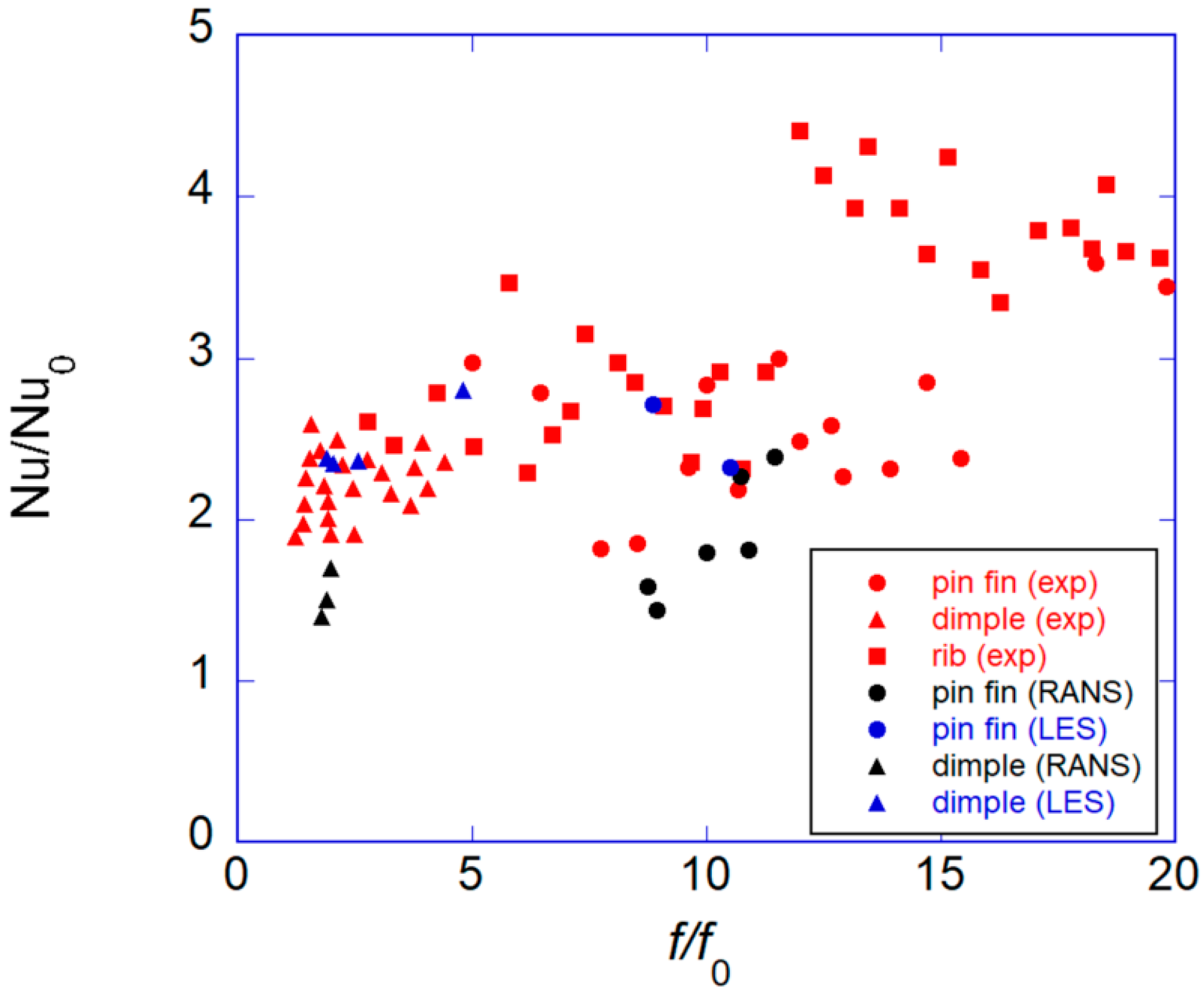
2.3. Thermal Performance Analysis

Thermal performance, a critical factor influencing blade durability, efficiency, and overall lifespan, has been extensively analyzed using LES data. LES provides more accurate and detailed insights compared to RANS, enabling the optimization of blade cooling strategies. Published LES studies on pin fins have examined varying heat loads, thermal boundary conditions, and configurations, as outlined below.
Saha and Acharya [31] used LES to study heat transfer in an in-line cubic pin fin array, showing a 1.8–2.0× enhancement over smooth ducts. At low Reynolds numbers, pin fins contributed 5–9% more heat transfer than the top wall, but at higher Reynolds numbers, both surfaces had comparable cooling. Jogee and Anupindi [44] analyzed a staggered pin fin array in a gas turbine trailing edge, finding localized Nusselt number peaks due to vortex interactions. Higher pressures increased Nusselt numbers, while lower pressures raised heat flux. Lee et al. [45] applied SAS to a short pin fin array, showing heat loads affected vortex shedding and turbulence, keeping Nusselt numbers steady despite Reynolds number drops.
In a more recent LES-based study, the authors [46] analyzed thermal performance in a pin fin channel under three heating loads relevant to turbine blade cooling. As heat loads increased, wall jets formed near heated surfaces, significantly altering turbulence structures and enhancing heat transfer. The study evaluated two subgrid-scale models, DKEM and WALE, both of which produced reliable results validated against direct numerical simulation and experimental data. Findings highlighted the effects of heat loads on flow and temperature fluctuations, turbulent kinetic energy, and stress anisotropy, offering valuable guidance for refining RANS models to improve thermal performance predictions.

2.4. Pin Fin Channel with Film Cooling

Most LES studies on pin fin channels have traditionally focused on idealized geometries with uniform duct height and periodic pin fin arrangements. These investigations primarily aimed to verify predictive accuracy by comparing LES results with those from RANS simulations and experimental data, while also analyzing flow structures to elucidate mechanisms driving local heat transfer distribution. However, with advancements in computational power, LES has begun to explore more realistic geometries, such as those resembling the trailing edges of gas turbine blades. In many recent studies, DES, a hybrid LES approach, has been used in place of traditional LES.
Effendy et al. [38] used DES to study pin fin cooling in a trailing-edge cutback, validating simulations against experiments and analyzing blowing ratios. Their results showed strong agreement with data, with enhanced turbulence and heat transfer improving cooling efficiency. Jamaldi and Hassan [39] applied DES with the SA model to a five-row pin fin array, examining heat transfer, discharge coefficient, and film cooling effectiveness. Their findings showed heat transfer fluctuations on pin surfaces and increased discharge coefficients at higher blowing ratios, with cooling effectiveness strongly influenced by turbulent mixing.

2.5. Conjugate Heat Transfer Analysis

Early research on pin fin channels primarily focused on convective heat transfer using simplified isothermal or constant heat flux boundary conditions. Recent studies, such as those by Bauer and Tyacke [43], have expanded to include conjugate heat transfer analysis, incorporating thermal conduction within pin structures. This shift reflects a growing emphasis on more realistic simulations, particularly for cooling applications where both conduction and convection play critical roles [48]. Additionally, Lee et al. [45,46] improved the modeling of variable heat loads and fluxes to better represent the complex thermal environments in operational gas turbines. The adoption of multi-physics approaches underscores the demand for high-fidelity simulations that closely mirror real-world turbine conditions.
Bauer and Tyacke [43] compared RANS and LES methods for predicting conjugate heat transfer in low Reynolds number flow over pin fin surfaces. Their findings demonstrated that LES predictions closely matched experimental data, with a heat transfer error of only 7.7%, whereas RANS predictions showed significantly larger errors, reaching up to 40%. The study also revealed that employing a one-equation LES turbulence model slightly enhanced heat transfer predictions compared to traditional numerical LES, indicating that more complex models do not always yield superior results. Moreover, their time-dependent analysis of flow and temperature fields showed that approximately 1800 through-flow times were required for full flow development, while 150 through-flow times were necessary to achieve statistically stationary results.

3. Large Eddy Simulation of Flow and Heat Transfer in Dimpled Channels

The pin fin duct has traditionally been used as an internal cooling structure for the trailing edge of gas turbine blades. Recently, dimpled surfaces have emerged as a promising alternative for narrow cooling channels at the trailing edge, offering significant enhancements while maintaining a relatively low-pressure drip compared to rib turbulators [7,27]. A dimple, characterized as a shallow recess on the wall surface, alters the flow field in ways that improve thermal performance [48]. Flow visualization studies have highlighted key features of dimple-induced flow, including the formation of low-velocity recirculation zones inside the dimple surface and the generation of two pairs of vortices as the fluid interacts with the dimpled surface (Figure 4a). Additionally, the heat transfer coefficient values across the dimple, with lower values in the upper region and higher values downstream [49].
Experimental research on dimpled channels began in the 2000s [27], with LES studies consistently appearing since 2008. This review analyzes 18 LES-based studies on dimpled channels, summarized in Table 2. Compared to the pin fin studies listed in Table 1, dimpled channel research exhibits a greater reliance on pure LES methods, with some studies even utilizing direct numerical simulations (DNS). While pin fin research often examines heat transfer variations along the flow direction, studies on dimples typically focus on fully developed flow conditions, which reduces computational demands.
Dynamic SGS models are the most commonly used in these simulations. Most investigations were conducted at Reynolds numbers around 10,000, representative of internal gas turbine conditions, while DNS studies were limited to lower Reynolds numbers, around 3000. The majority of studies focused on dimples with a depth-to-diameter ratio (d/D) of 0.2, and channel heights (H) were typically set at 2.5 times the dimple depth (H/d = 2.5), making these configurations particularly relevant for trailing-edge cooling applications.
A key focus of these studies is understanding the flow mechanisms behind heat transfer enhancement in dimpled channels, which is often achieved through detailed LES flow field analysis. Additionally, several studies explored the impact of innovative dimple geometries, alternative arrangements, and the integration of protrusions or other turbulence promoters to further enhance heat transfer. Rotational effects and pulsating main flows, both of which are effectively captured by LES, have also been examined. The following sections provide a detailed discussion of these topics.

3.1. Flow Structure and Mechanisms of Heat Transfer Enhancement

Early LES studies [50,52] on dimpled channels demonstrated that LES provides more accurate local heat transfer predictions than RANS. As shown in Figure 5, RANS models [68] tend to underpredict heat transfer, with local distributions deviating significantly from experimental data. The experiments reveal a symmetrical heat transfer distribution along the flow direction, whereas RANS results using the nonlinear eddy-viscosity model (NLEVM) exhibit an asymmetrical pattern. This asymmetry likely arises due to the limitations of eddy-viscosity models in fully capturing unsteady vortex structures and flow separation, leading to numerical asymmetry despite the symmetric geometry and flow conditions. In contrast, the Reynolds stress model (RSM), which explicitly solves for Reynolds stresses, corrects this asymmetry, the heat transfer distribution behind the dimple rim still deviates from experimental observations. In contrast, LES [50,52] closely matches experimental data, accurately capturing high heat transfer at the reattachment point within the dimple and along the downstream rim. These findings have driven further LES investigations into flow structures, vortex dynamics, and heat transfer mechanisms in dimpled channels.
Elyyan and Tafti [50] performed LES simulations on channels with dimples and protrusions on opposing heated walls, investigating Reynolds numbers 220, 940, and 9300 to cover laminar through fully turbulent regimes. Their findings attributed heat transfer enhancement on the dimpled surface to turbulence generated by the separated shear layer and the downstream rim of the dimple. Lee et al. [52] conducted LES to examine flow and heat transfer in channels at bulk Reynolds numbers of 5000 and 20,000. At a Reynolds number of 5000, the Nusselt number ratio remained high, despite a decrease in the heat transfer coefficient caused by weaker shear layer vortices.
Turnow et al. [54,55,56] used LES and URANS to study vortex dynamics in dimpled channels, showing that vortex-induced flow separation enhances heat transfer with minimal pressure loss. LES at Re = 20,000–40,000 revealed unsteady vortices and tornado-like structures. Their follow-up study [68] validated LES with LDV, finding that a depth-to-diameter ratio of 0.26 improved heat transfer by 201%. In [69], they used IDDES to analyze higher Reynolds and Prandtl numbers, achieving accurate flow predictions with lower computational costs than LES.

3.2. Geometric Variations and Their Effects on Heat Transfer

LES has been extensively used to study the impact of various dimple shapes, sizes, and arrangements on heat transfer and flow dynamics. While spherical dimples were the first to be introduced, alternative designs have since been proposed to enhance heat transfer between the dimple interior and the channel wall, as illustrated in Figure 6 [70,71,72,73]. Although experimental methods primarily evaluate the performance of new dimple geometries, LES has been instrumental in uncovering the mechanisms driving heat transfer enhancement and optimizing geometric configurations.
Early LES studies examined the influence of spherical dimple depth and arrangement on heat transfer and flow behavior. Lee et al. [52] investigated dimpled channels with depths of 0.2 D and 0.3 D at a bulk Reynolds number of 20,000. They found that deeper dimples caused flow reattachment to occur farther downstream, resulting in reduced heat transfer compared to shallower dimples. Additionally, their comparison of in-line and staggered dimple arrangements [66] revealed that staggered configurations significantly enhanced heat transfer, while in-line arrangements caused reduced heat transfer within the spanwise gaps.
Chen et al. [57] used DES to study rounded dimples, finding that a 15% asymmetric depth ratio and 15% streamwise skewness optimized heat transfer by enhancing secondary flows and vortices while minimizing pressure loss. Xie et al. [61] combined experiments with SBES, showing upstream-rounded dimples improved heat transfer by 11.4% with only a 5.2% pressure loss increase. DNS by Yoon et al. [59] revealed spanwise circulation in tear-drop dimples, while Nourin et al. [64] found spherical dimples maximized heat transfer but increased pressure loss, whereas leaf-shaped dimples were more efficient at high Reynolds numbers.

3.3. Dimples with Protrusions or Turbulence Enhancers

Beyond optimizing dimple shapes and arrangements, numerous studies have explored alternative turbulence enhancers to improve the thermal performance of gas turbine cooling channels. Traditional strategies include the use of protrusions [74]—essentially the inverse of dimples—and the combined effects of ribs [75], vortex generators [76], and trip wires [77]. LES has been pivotal in understanding these mechanisms. For instance, Elyyan and Tafti [60] showed that heat transfer enhancement on dimple surfaces arises from turbulence generated by the separated shear layer and downstream rim, whereas protrusion surfaces benefit primarily from flow impingement and acceleration. Pressure drops in dimple-protrusion configurations were found to result from both skin friction and form losses, with form losses increasing at higher Reynolds numbers.
Chen et al. [58] used DES to study dimple-protrusion channels, showing that larger depth-to-height ratios increase friction and heat transfer, with peak Nusselt numbers upstream of protrusions and downstream of dimples. Li et al. [63] found that vortices in dimpled channels drive local heat transfer peaks, while Jeong et al. [60] showed that crescent-shaped vortex generators improved performance over standard dimples. Zhang et al. [62] used DDES to reveal that hybrid V-shaped rib–dimple structures maximize heat transfer by enhancing vortex mixing and disrupting recirculation zones.

3.4. Influence of Rotation and Flow Pulsations

While earlier LES studies primarily explored the influence of geometric variations on flow and heat transfer in dimpled channels, factors such as rotation-induced centrifugal forces and flow unsteadiness—critical in trailing-edge cooling of gas turbines—have received comparatively less attention. These factors, including Coriolis forces and flow pulsations, significantly affect thermal performance [13] and are best studied using LES, which offers superior accuracy over RANS [23].
Elyyan and Tafti [51] investigated the effects of Coriolis forces and dimple-protrusion depth in rotating channels. Their findings indicated that dimples on the trailing side are particularly sensitive to destabilizing Coriolis forces, with heat transfer augmentation increasing from 2.3 to 3.8 as the rotation number (Ro) increased to 0.77 for deeper dimples (d/D = 0.3). Protrusions were more effective at lower Ro values (|Ro| < 0.2), while dimples provided better performance at higher Ro values. However, deeper dimples also incurred greater frictional losses.
Yamamoto et al. [66] used LES to study pulsating flow over tear-drop dimples, finding a 9–12% increase in Nusselt number, an 18–21% rise in friction, and a 3–6% boost in heat transfer efficiency due to periodic flow-separation bubbles enhancing swirling intensity. Inokuma et al. [67] expanded this analysis across six dimple geometries, showing peak heat transfer at a Strouhal number of 0.30, where pulsation shifted swirling separation bubbles closer to dimple edges, intensifying turbulent heat flux. These studies demonstrate the effectiveness of flow pulsation in enhancing thermal performance in dimpled channels.

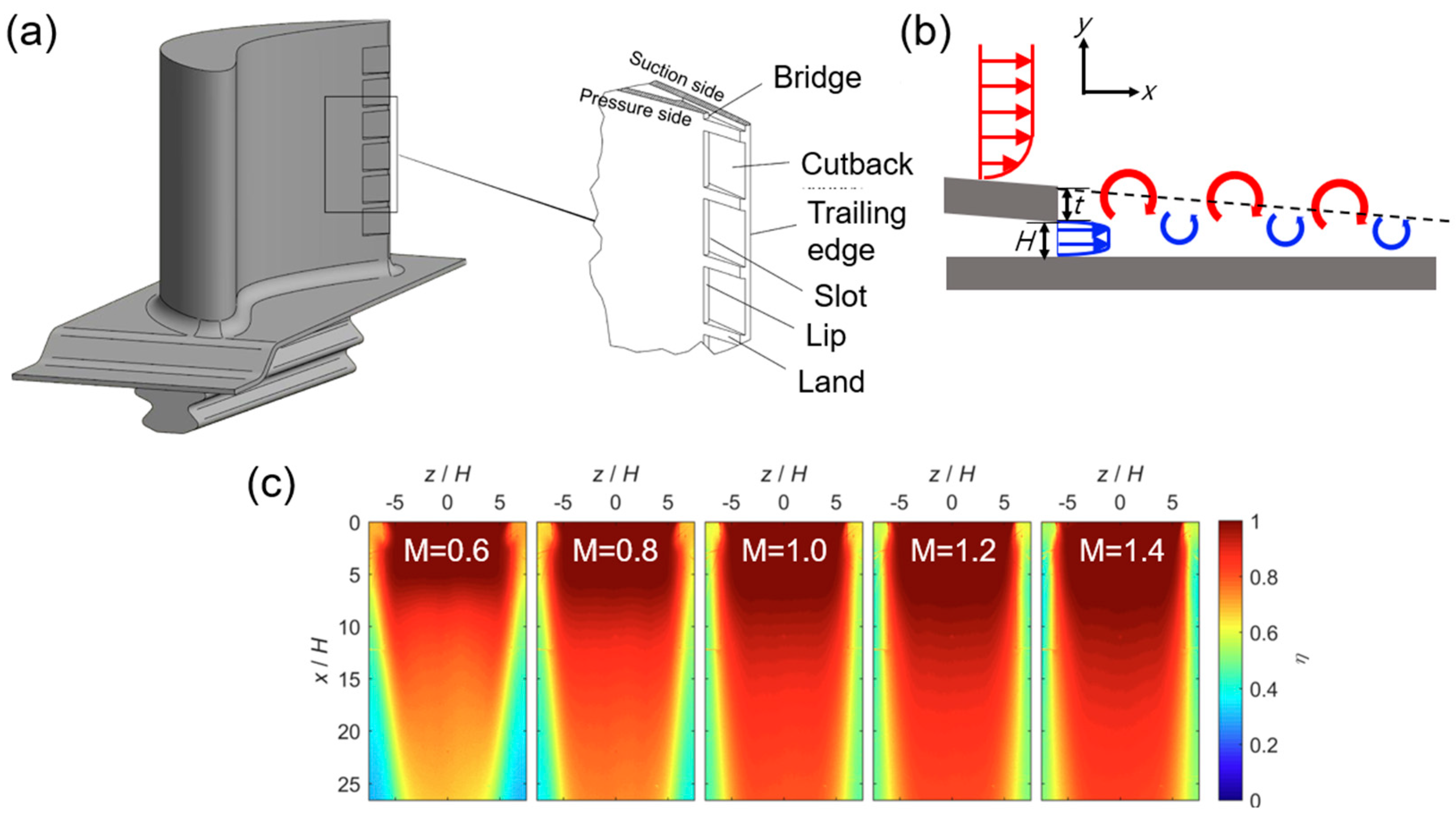
4. Large Eddy Simulation of Film Cooling at the Trailing Edge

The trailing edge of a gas turbine blade typically features a narrow, tapering geometry with a wedge or triangular cross-section. This shape limits the available space for internal cooling channels and cooling hole placement, making the design of film cooling systems more complex compared to areas such as the pressure or suction sides of the mid-chord. To effectively cool this region, film cooling often employs slot-shaped or cutback holes, as shown in Figure 7a. These configurations are particularly effective for maintaining uniform coolant distribution across the narrow surface.
These designs differ from the cylindrical or fan-shaped holes used in other blade regions. As shown in Figure 7b, the inclination angle is minimal, eliminating lift-off issues and resulting in high film cooling effectiveness in the upstream region, as shown in Figure 7c. Coolant is often supplied through cooling channels that incorporate heat transfer enhancers, such as pin fin arrays, to improve film cooling performance. These factors require specialized designs and advanced simulation techniques, such as LES, to optimize cooling efficiency. This study reviews 20 papers that utilized LES for film cooling at the trailing edge, summarized in Table 3.
Since the 2010s, LES for cutback film cooling has gained traction, particularly in Europe, with significant contributions from China starting in the 2020s. Due to the complexity of internal cooling paths, which often include pin fins, hybrid LES approaches are more commonly used than pure LES. A major challenge in LES for film cooling—an external flow phenomenon—is generating realistic inflow conditions in real-time. Hybrid LES addresses this by using a RANS region at the inlet, where turbulence intensity is typically specified for the velocity boundary condition, often with the aid of a long lip.
The blowing ratio (M), a critical parameter in film cooling, has been primarily studied within the range of 0.5 to 2. Additionally, the thickness of the lip (t) in cutback film cooling plays a significant role. While lip thickness is often set equal to the jet slot height (H), some studies have explored the effects of varying this thickness. Key research areas include the influence of the blowing ratio on flow and film cooling performance, as well as the effects of coolant supply and lip geometry. The following sections will review these studies, organized by topic.

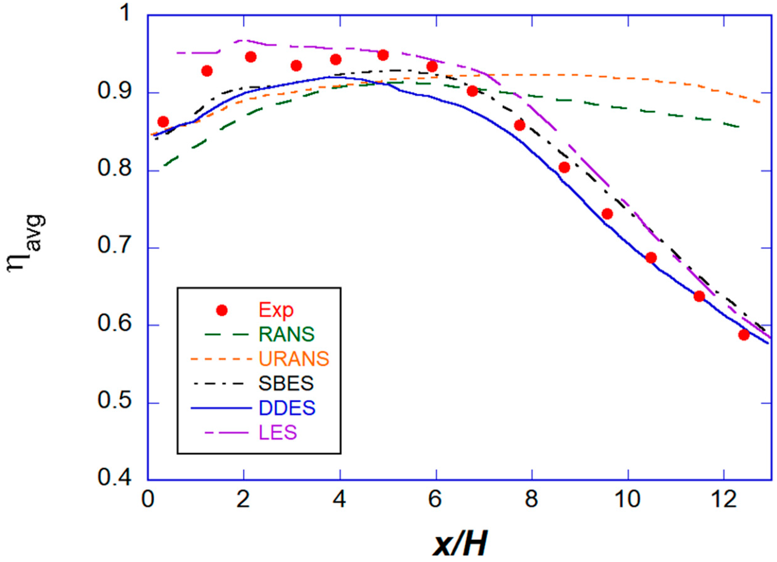
4.1. Comparative Study of Modeling Approaches (RANS, LES, Hybrid)

This section reviews a comparative analysis of various CFD methods used to model cutback film cooling, focusing particularly on early LES studies. It evaluates the performance of different turbulence models, including LES, hybrid LES approaches such as SAS and DDES, and traditional RANS and URANS models. The evaluation is based on comparisons with experimental data to highlight the strengths and limitations of these methods in predicting film cooling effectiveness, especially in the challenging downstream region of the trailing edge.
Figure 8 compares the film cooling effectiveness predicted by various CFD methods against experimental results. Both LES and hybrid LES models, such as SBES and DDES, show excellent agreement with experimental data. In contrast, RANS and URANS models tend to overestimate film cooling effectiveness, particularly in the downstream region. Schneider et al. [81] emphasized the ability of LES to accurately predict mean flow and turbulence statistics, while RANS models failed to account for the influence of coherent structures on turbulent heat transfer.
Similarly, Ravelli and Barigozzi [82] applied URANS to model the mixing between mainstream and coolant but could not replicate the observed decrease in cooling effectiveness downstream. SAS provided improved predictions by better capturing vortex shedding from the cutback lip, although at a lower frequency than observed in experiments. As shown in Figure 8, hybrid LES approaches like SBES and DDES offer reliable predictions of cutback film cooling effectiveness, even in the difficult downstream region.

4.2. Influence of Blowing Ratio on Flow Structure and Film Cooling Effectiveness

Blowing ratio (M) is a critical factor influencing the effectiveness of trailing-edge cutback film cooling, as demonstrated by LES-based studies. Research has shown that increasing the blowing ratio can enhance cooling effectiveness up to an optimal point. However, beyond this point, thermal mixing and vortex dynamics reduce the benefits. Key flow features, including von Kármán vortices, Kelvin–Helmholtz instabilities, and hairpin vortices, emerge under different blowing ratio conditions and significantly affect turbulent heat flux and wall cooling performance. These findings highlight the complex relationship between coolant injection parameters and coherent vortex structures, offering valuable insights into optimizing film cooling designs for better thermal management.
Figure 7c illustrates that the film cooling effectiveness of the cutback increases with the blowing ratio from 0.5 to 1.0, but shows minimal improvement beyond this value. Schneider et al. [79] observed that, within a certain range, increasing the blowing ratio could reduce cooling effectiveness due to intensified thermal mixing. This reduction was linked to dominant clockwise-rotating coherent structures that generate turbulent heat flux both upstream and along the wall, enhancing mixing and reducing cooling performance.
Naqavi et al. [85] used LES to study wall jet interactions with a heated boundary layer, finding that for M < 1.0, von Kármán vortices enhanced cooling, while for M > 1.0, Kelvin–Helmholtz instabilities reduced effectiveness. Cooling mechanisms shifted from wall-normal velocity and turbulent heat flux to turbulence-dominated heat transfer at higher M. Ravelli and Barigozzi [84] used SBES to confirm vortex formation effects, capturing Kelvin–Helmholtz instabilities, hairpin vortices, and vortex shedding in the cutback region, aligning with experimental data.

4.3. Impact of Lip and Land Geometry on Cutback Film Cooling Performance

Hybrid LES approaches have been widely used to investigate the impact of lip and land geometries on the performance of trailing-edge cutback film cooling. These studies focus on the relationship between geometric modifications and the resulting flow dynamics, vortex structures, and cooling effectiveness. Researchers have examined how parameters such as the lip thickness-to-slot height ratio (t/H), ejection slot angles, and land extensions influence thermal mixing and aerodynamic losses. By employing advanced simulation techniques, such as DDES, key mechanisms—such as vortex shedding, coolant convergence, and distinctive flow patterns—have been identified, all of which play a crucial role in governing the thermal and aerodynamic performance of turbine blade trailing-edge configurations.
Effendy et al. [86,87] used DES to study trailing-edge cutback film cooling, finding that increasing t/H intensified thermal mixing, reducing cooling effectiveness, while a 15° ejection slot angle optimized cooling along breakout walls. Luo et al. [93] explored whisker-inspired structures using DDES, showing that the PP configuration improved aerodynamics and cooling by transforming trailing-edge vortices into hairpin vortices. Wang and Yan [90] examined land extensions, revealing their impact on vortex structures, mixing region thickness, and cooling performance, with distinct vortex patterns enhancing coolant distribution.

4.4. Combined Effects of Internal Rib Configurations or Novel Internal Structures

This section reviews LES studies on cutback film cooling, focusing particularly on the combined effects of internal rib configurations and novel internal structures. These studies examine various geometric designs, including rib arrays, pin fin structures, and dimpled surfaces, to evaluate their impact on coolant distribution, heat transfer efficiency, and overall film cooling performance. By investigating different configurations and operating conditions, such as blowing ratios and lip thicknesses, these studies provide valuable insights into the mechanisms that enhance turbine blade thermal management. The following paragraphs summarize key findings from several significant LES studies on this topic.
Among the 20 studies summarized in Table 3, 8 of them focus primarily on recent investigations of structures like pin fins, ribs, and dimples in the coolant slot. Wang and Yan [90] studied rib and pin fin arrays in cutback film cooling, finding that the five-row pin fin array at M = 0.5 provided the best cooling, though performance varied with increasing blowing ratios. Li et al. [88] examined oblong dimples in V-patterns, showing that higher blowing ratios improved cooling effectiveness and heat transfer, with tighter dimples boosting cooling by 5%. Jia et al. [95] found that latticework ducts [100] enhanced cooling efficiency by creating large-scale vortices, while rib and pin fin arrays produced vortex pairs. Their follow-up study [96] showed that film cooling efficiency initially declined and then improved with increased blowing ratios and lip thickness.

4.5. Interaction with Upstream Film Cooling

The effectiveness of film cooling on a gas turbine blade decreases downstream, leading to the use of multiple rows of coolant injection holes. Research on multi-row film cooling has focused on various blade sections, such as the mid-chord [101], endwall [102], and leading edge [103]. Ravelli and Barigozzi [84], in their LES study of cutback film cooling, initially considered upstream film cooling, but subsequent studies typically excluded it. Recent research, however, has revisited the inclusion of upstream film cooling in the analysis.
Xu et al. [96] compared pure and fan-shaped hole cutback slots using DDES simulations, finding that the fan-shaped hole improved film effectiveness, though higher blowing ratios reduced turbulent heat transport. Wang et al. [97] validated these findings with experiments using pressure-sensitive paint (PSP) and particle image velocimetry (PIV), observing a non-monotonic trend in cooling effectiveness linked to changes in vortex structure and shear layer modification. They also proposed empirical correlations for slot and film hole configurations to quantify coolant mixing impacts on cooling.

5. Future Works

While the 54 reviewed papers provide valuable insights into flow dynamics and heat transfer characteristics at the trailing edges of gas turbine blades using LES, several areas require further investigation to optimize cooling performance. Future research will focus on the following key areas:

5.1. LES Investigations of Advanced Trailing Edge Cooling Geometries

Figure 9 illustrates the thermal-hydraulic performance of rib turbulators, pin fins, and dimpled channels using experimental data, RANS, and LES. Experimental results (red) indicate that rib turbulators achieve the highest heat transfer but with substantial pressure loss, whereas dimples provide a favorable balance between heat transfer enhancement and frictional penalty. Pin fins exhibit moderate improvements with a gradual increase in drag. RANS (black) underestimates heat transfer, particularly for pin fins and dimples, due to its limitations in capturing flow separation and reattachment. In contrast, LES (blue) offers more accurate predictions, closely aligning with experimental trends by resolving unsteady turbulent structures.
Future LES research on internal cooling of trailing edges should prioritize the design and optimization of novel geometries to improve heat transfer and reduce pressure losses. Recent advancements in pin fin designs—such as triangular, teardrop, and airfoil-like cross-sections [104,105]—as well as innovative arrangements like detached, inclined, and curved fins [106,107] have shown promise in both experimental and RANS studies. Furthermore, hybrid cooling configurations that combine dimples with features like rib turbulators, protrusions, and vortex generators offer the potential for optimizing heat transfer while minimizing pressure losses and thermal stresses. However, the interactions between these combined features remain complex and are not yet fully understood.
The advent of additive manufacturing has broadened the possibilities for creating intricate and unconventional geometries [108], including twisted and branched pins [109,110] and advanced dimple designs. These complex structures hold considerable potential for improving cooling efficiency, but they also introduce significant modeling challenges due to the turbulent and thermal effects they generate. LES plays a crucial role in overcoming these challenges by providing detailed insights into the aerodynamic and thermal performance of these advanced designs, helping to optimize next-generation cooling channels for gas turbines.
In cutback film cooling, LES has been extensively used for shape optimization, particularly for the lip and land regions. Recent studies have also incorporated pin fin and dimple designs. It is anticipated that LES will continue to be instrumental in exploring new internal structures, further advancing the development of external cooling technologies.

5.2. Multi-Physics Simulations Integrating Thermal and Structural Behavior

In trailing-edge cooling, the interaction between internal cooling structures and external film cooling requires a conjugate heat transfer (CHT) analysis that accounts for heat conduction through the blade material. This analysis becomes particularly important when considering cutback geometries, which may compromise structural integrity or complex shapes enabled by additive manufacturing, which could exacerbate mechanical challenges [111]. In this context, multi-physics simulations that integrate thermal and structural analyses are essential, and LES can provide significant insights into the underlying flow and thermal phenomena.
For internal cooling, pin fin arrays are critical in enhancing heat transfer along channel walls. However, the efficiency of the pin fins themselves, including the effects of conduction, has not been thoroughly investigated. To fully understand their performance, the fin efficiency of pin fins must be clarified through detailed CHT analyses. In contrast, dimples offer advantages over pin fins, including reduced structural weaknesses and more uniform heat transfer distribution. Although dimples are less commonly studied in terms of fluid–structure interaction and thermal stresses, ongoing research is focused on optimizing their performance through shape innovations and hybrid configurations.
Future research should integrate thermal and structural analyses to address the combined effects of thermal loads and mechanical stresses, particularly in high-stress regions like the trailing edge [112]. This includes considering factors such as temperature-dependent material properties, fatigue from thermal cycling, and resilience to thermal shock. As gas turbines are increasingly operated at higher temperatures to improve efficiency, these comprehensive analyses will become vital for optimizing blade durability and extending their operational lifespan. LES-based CHT analyses, combined with advanced material and structural modeling, will be crucial in achieving these objectives.

5.3. Effects of Rotation and Unsteady Flow on the Trailing Edge Cooling

When applying film cooling, the external flow around turbine blades often involves unsteady phenomena, such as wakes or shock waves [113]. LES is particularly effective at capturing transient responses to rapidly changing boundary conditions, which are common in industrial gas turbine environments [22,23]. By incorporating time-dependent inflow conditions, LES can offer detailed insights into how these unsteady effects influence film cooling performance, especially at the trailing edge. These studies can help develop more effective cooling strategies for components exposed to non-uniform heat loads.
Furthermore, cooling channel flows are often characterized by transient, pulsating, and rotational effects, which challenge conventional RANS methods. LES is necessary to accurately capture these effects. Future LES investigations should replicate real-world turbine operating conditions, including fluctuating flow velocities and rotating reference frames [51,67]. Gas turbines operate in highly dynamic environments where unsteady flows and pulsations significantly affect cooling performance. Advancing our understanding of these phenomena will be crucial for designing resilient cooling systems that can adapt to transient heat loads and varying operational demands.

6. Conclusions

This review evaluated 54 studies, employing LES to investigate trailing-edge cooling strategies for gas turbine blades, with a focus on pin fin arrays, dimpled surfaces, and cutback film cooling. These studies assessed the potential of various geometries to enhance heat transfer efficiency while minimizing aerodynamic losses. LES has proven invaluable in capturing the complex, unsteady flow phenomena critical to optimizing cooling performance. The key findings of this comprehensive review are summarized as follows:
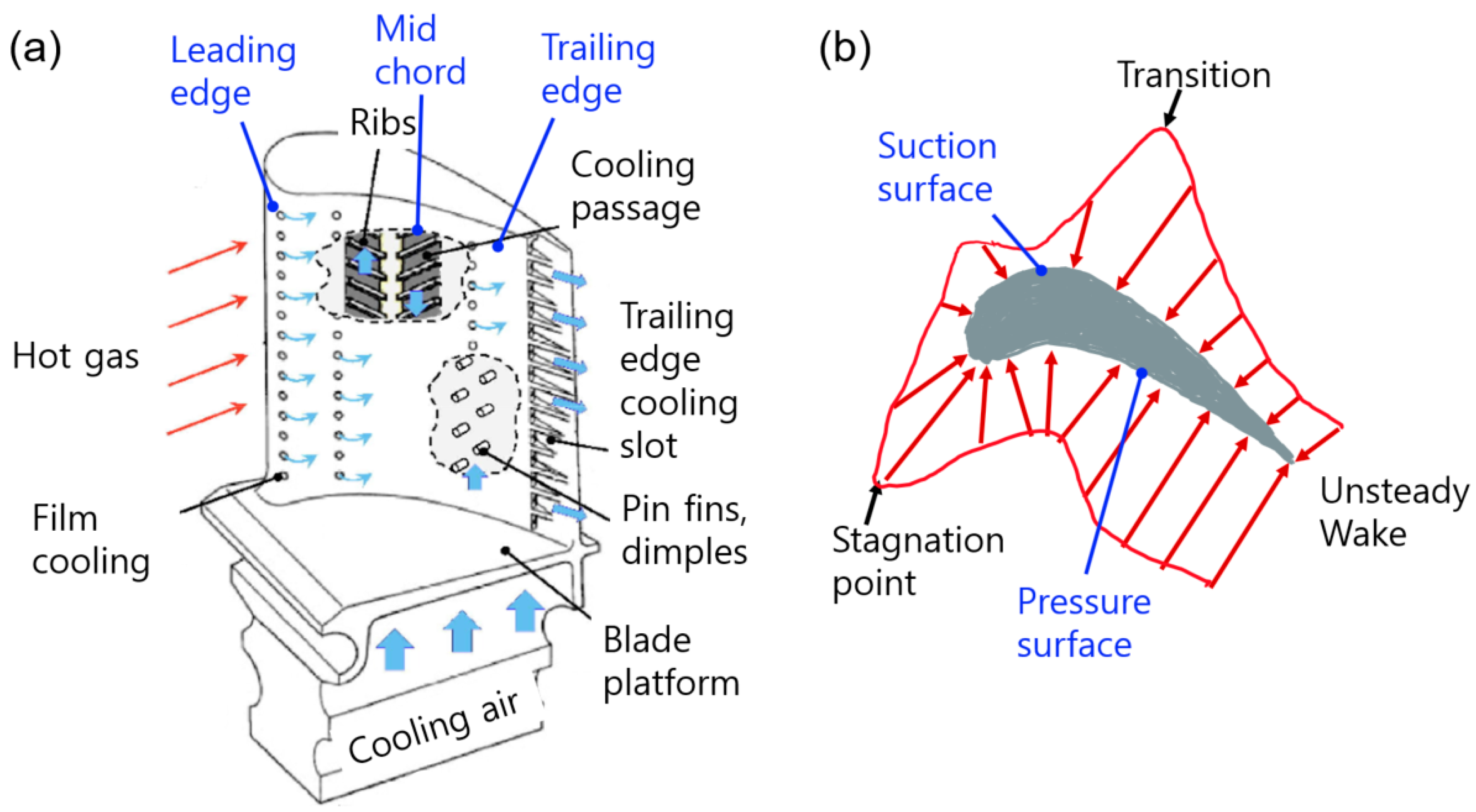
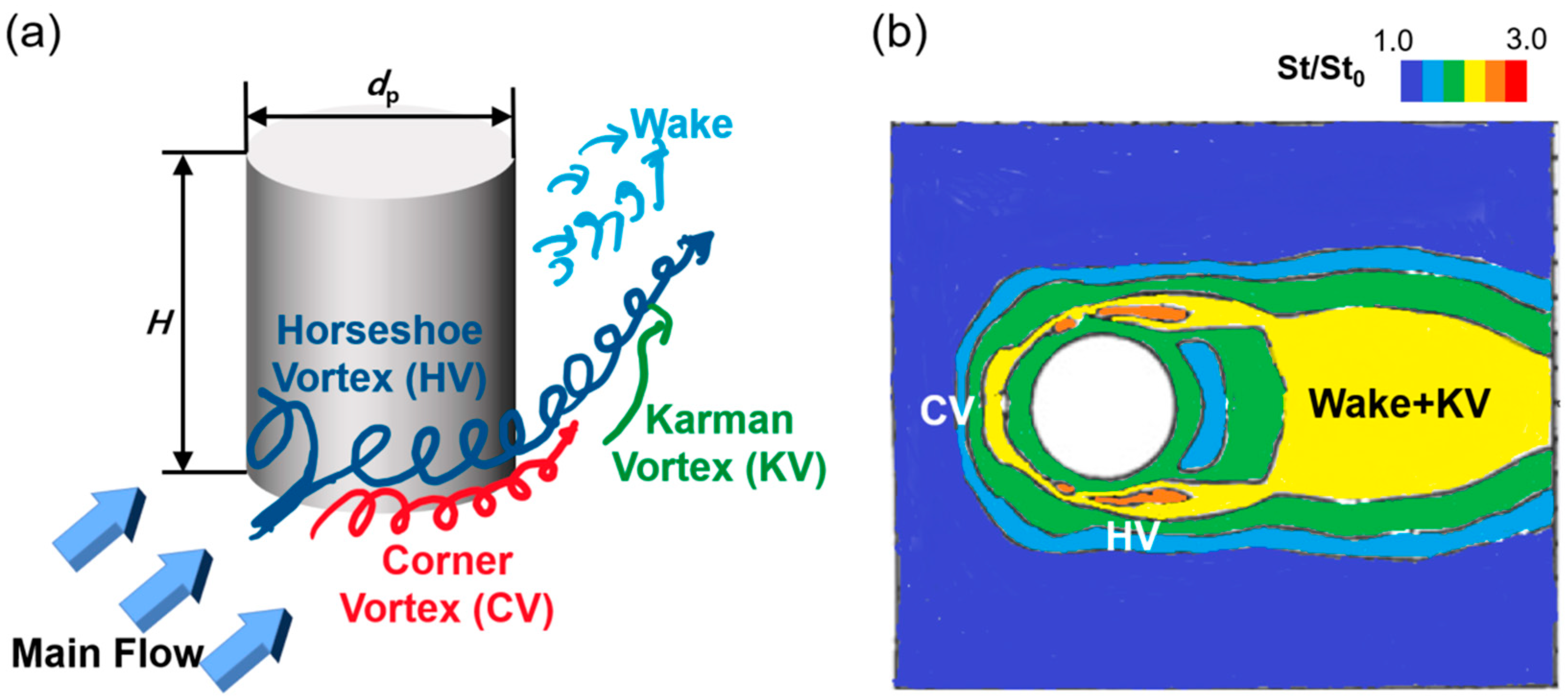
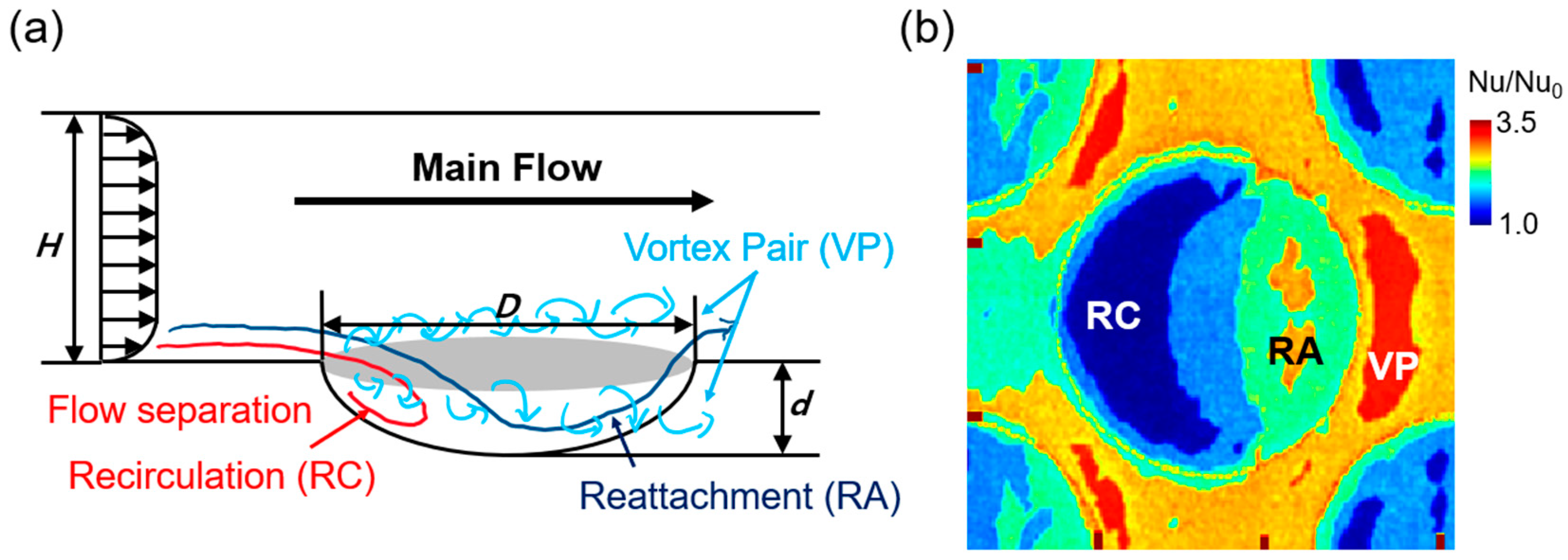
  • Large eddy simulation (LES) has proven its capability in resolving flow features that are often inadequately captured by Reynolds-Averaged Navier–Stokes (RANS) simulations. It has effectively modeled key phenomena, including horseshoe and corner vortices in pin fin arrays, shear layer vortices in dimples, complex interactions between dimple exit flows and the main flow, and shear layer-generated vortices in cutback film cooling. These insights have greatly advanced the understanding of heat transfer mechanisms and the distribution of film cooling effectiveness, which is particularly crucial for cooling the trailing edge due to its more complex geometry compared to the mid-chord region;
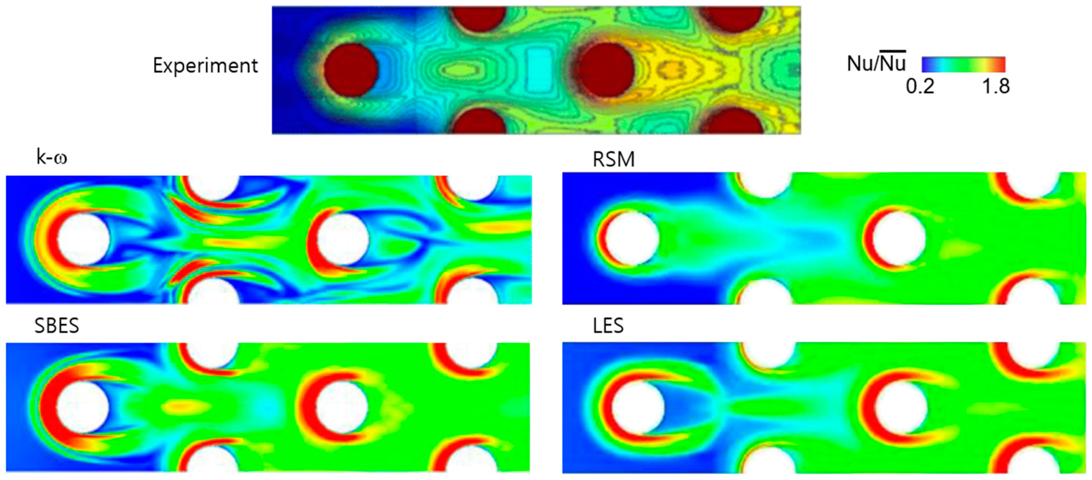
  • LES has consistently outperformed RANS in predicting heat transfer within pin fin and dimpled channels, which are commonly used for cooling the trailing edge of turbine blades. RANS often underestimates the heat transfer rate in these configurations, whereas LES provides a distribution that more closely matches experimental observations, with reduced sensitivity to boundary conditions and turbulence models. For example, LES avoids the asymmetric or experimentally unobserved local heat transfer peaks that can appear in RANS results depending on the turbulence model, demonstrating its greater reliability across different subgrid-scale (SGS) models;
  • Similar to film cooling through discrete holes in the mid-chord region, LES has provided more accurate predictions of cutback film cooling effectiveness, whereas RANS tends to overestimate it. Although LES has yet to achieve fully accurate heat transfer predictions for film cooling in the mid-chord, we anticipate more successful results for cutback film cooling, where the flow is relatively less complex. This advancement will be crucial for conjugate heat transfer analysis, which accounts for both cutback film cooling and internal heat transfer enhancement;
  • LES has provided precise predictions of turbulence statistics, an area where RANS often fall short in trailing-edge cooling scenarios. While RANS struggles to accurately capture turbulence within the shear layer inside dimples or in cutback film cooling—often showing deviations depending on the turbulence model—LES reliably predicts these flow features regardless of the SGS model. This capability has deepened the understanding of heat transfer characteristics and significantly contributed to turbulence model development. As data-driven approaches, such as machine learning, integrate with LES, further advancements in turbulence modeling and heat transfer prediction are expected;
  • Recent LES studies have successfully combined internal and external flow simulations for trailing-edge cooling, providing a comprehensive understanding of these interconnected systems. With ongoing advancements in computational capabilities, future research is expected to delve into multi-physics simulations. These will integrate CHT and flow-structure interactions, addressing the thermal and mechanical demands of next-generation turbine designs.
LES continues to be a transformative tool in advancing the design and analysis of trailing-edge cooling systems. Its ability to resolve intricate flow dynamics, predict heat transfer with high fidelity, and adapt to emerging computational techniques ensures its critical role in optimizing turbine blade cooling performance for future high-efficiency gas turbines.

Funding

This research received no external funding.

Data Availability Statement

Data are included within this article.

Conflicts of Interest

The author declares no conflicts of interest.

References

  1. Takeishi, K. Evolution of turbine cooled vanes and blades applied for large industrial gas turbines and its trend toward carbon neutrality. Energies 2022, 15, 8935. [Google Scholar] [CrossRef]
  2. Mohamed, O.; Khalil, A. Progress in modeling and control of gas turbine power generation systems: A survey. Energies 2020, 13, 2358. [Google Scholar] [CrossRef]
  3. Stefanizzi, M.; Capurso, T.; Filomeno, G.; Torresi, M.; Pascazio, G. Recent combustion strategies in gas turbines for propulsion and power generation toward a zero-emissions future: Fuels, burners, and combustion techniques. Energies 2021, 14, 6694. [Google Scholar] [CrossRef]
  4. Chowdhury, T.S.; Mohsin, F.T.; Tonni, M.M.; Mita, M.N.H.; Ehsan, M.M. A critical review on gas turbine cooling performance and failure analysis of turbine blades. Int. J. Thermofluids 2023, 18, 100329. [Google Scholar] [CrossRef]
  5. Haque, M.A.; Nemitallah, M.A.; Abdelhafez, A.; Mansir, I.B.; Habib, M.A. Review of fuel/oxidizer-flexible combustion in gas turbines. Energy Fuels 2020, 34, 10459–10485. [Google Scholar] [CrossRef]
  6. Han, J.C. Fundamental gas turbine heat transfer. J. Therm. Sci. Eng. Appl. 2013, 5, 021007. [Google Scholar] [CrossRef]
  7. Ligrani, P. Heat transfer augmentation technologies for internal cooling of turbine components of gas turbine engines. Int. J. Rotating Mach. 2013, 2013, 275653. [Google Scholar] [CrossRef]
  8. Yeranee, K.; Rao, Y. A review of recent studies on rotating internal cooling for gas turbine blades. Chin. J. Aeronaut. 2021, 34, 85–113. [Google Scholar] [CrossRef]
  9. Han, J.C. Advanced cooling in gas turbines 2016 Max Jakob memorial award paper. J. Heat Transf. 2018, 140, 113001. [Google Scholar] [CrossRef]
  10. Zhang, G.; Zhu, R.; Xie, G.; Li, S.; Sundén, B. Optimization of cooling structures in gas turbines: A review. Chin. J. Aeronaut. 2022, 35, 18–46. [Google Scholar] [CrossRef]
  11. Yang, X.; Hao, Z.; Feng, Z. An experimental study on turbine vane Leading-Edge film cooling with deposition. Appl. Therm. Eng. 2021, 198, 117447. [Google Scholar] [CrossRef]
  12. Dutta, S.; Singh, P. Opportunities in jet-impingement cooling for gas-turbine engines. Energies 2021, 14, 6587. [Google Scholar] [CrossRef]
  13. Unnikrishnan, U.; Yang, V. A review of cooling technologies for high temperature rotating components in gas turbine. Propuls. Power Res. 2022, 11, 293–310. [Google Scholar] [CrossRef]
  14. Cunha, F.J.; Chyu, M.K. Trailing-edge cooling for gas turbines. J. Propul. Power 2006, 22, 286–300. [Google Scholar] [CrossRef]
  15. Joo, J.; Durbin, P. Simulation of turbine blade trailing edge cooling. J. Fluids Eng. 2009, 131, 021102. [Google Scholar] [CrossRef]
  16. Casarsa, L.; Arts, T. Experimental investigation of the aerothermal performance of a high blockage rib-roughened cooling channel. J. Turbomach. 2005, 127, 580–588. [Google Scholar] [CrossRef]
  17. Murata, A.; Yano, K.; Hanai, M.; Saito, H.; Iwamoto, K. Arrangement effects of inclined teardrop-shaped dimples on film cooling performance of dimpled cutback surface at airfoil trailing edge. Int. J. Heat Mass Transf. 2017, 107, 761–770. [Google Scholar] [CrossRef]
  18. Horbach, T.; Schulz, A.; Bauer, H.J. Trailing edge film cooling of gas turbine airfoils—External cooling performance of various internal pin fin configurations. J. Turbomach. 2011, 133, 041006. [Google Scholar] [CrossRef]
  19. Kumar, S.; Amano, R.S. An investigation in the numerical approach to solve the heat transfer phenomenon in gas turbine. J. Energy Resour. Technol. 2021, 143, 080805. [Google Scholar] [CrossRef]
  20. Tucker, P.G. Trends in turbomachinery turbulence treatments. Prog. Aerosp. Sci. 2013, 63, 1–32. [Google Scholar] [CrossRef]
  21. Ali, U.; Kamran, M.S. Geometric optimization of a gas turbine blade cooling passage using CFD. Int. J. Therm. Environ. Eng. 2020, 17, 105–114. [Google Scholar]
  22. Tyacke, J.; Vadlamani, N.R.; Trojak, W.; Watson, R.; Ma, Y.; Tucker, P.G. Turbomachinery simulation challenges and the future. Prog. Aerosp. Sci. 2019, 110, 100554. [Google Scholar] [CrossRef]
  23. Tyacke, J.C.; Tucker, P.G. Future use of large eddy simulation in aero-engines. J. Turbomach. 2015, 137, 081005. [Google Scholar] [CrossRef]
  24. Ahn, J. Large eddy simulation of film cooling: A review. Energies 2022, 15, 8876. [Google Scholar] [CrossRef]
  25. Ahn, J. Large eddy simulation of flow and heat transfer in a ribbed channel for the internal cooling passage of a gas turbine blade: A review. Energies 2023, 16, 3656. [Google Scholar] [CrossRef]
  26. Holgate, J.; Skillen, A.; Craft, T.; Revell, A. A review of embedded large eddy simulation for internal flows. Arch. Comp. Methods Eng. 2019, 26, 865–882. [Google Scholar] [CrossRef]
  27. Du, W.; Luo, L.; Jiao, Y.; Wang, S.; Li, X.; Sunden, B. Heat transfer in the trailing region of gas turbines–A state-of-the-art review. Appl. Therm. Eng. 2021, 199, 117614. [Google Scholar] [CrossRef]
  28. Ravanji, A.; Lee, A.; Mohammadpour, J.; Cheng, S. Critical review on thermohydraulic performance enhancement in channel flows: A comparative study of pin fins. Renew. Sustain. Energy Rev. 2023, 188, 113793. [Google Scholar] [CrossRef]
  29. Ligrani, P.M.; Oliveira, M.M.; Blaskovich, T. Comparison of heat transfer augmentation techniques. AIAA J. 2003, 41, 337–362. [Google Scholar] [CrossRef]
  30. Chyu, M.K.; Natarajan, V. Heat transfer on the base surface of three dimensional protruding elements. Int. J. Heat Mass Transf. 1996, 39, 2925–2935. [Google Scholar] [CrossRef]
  31. Saha, A.K.; Acharya, S. Unsteady simulation of turbulent flow and heat transfer in a channel with periodic array of cubic pin-fins. Numer. Heat Transf. A 2004, 46, 731–763. [Google Scholar] [CrossRef]
  32. Delibra, G.; Hanjalić, K.; Borello, D.; Rispoli, F. Vortex structures and heat transfer in a wall-bounded pin matrix: Les with a RANS wall-treatment. Int. J. Heat Fluid Flow 2010, 31, 740–753. [Google Scholar] [CrossRef]
  33. Carnevale, M.; Salvadori, S.; Martelli, F.; Manna, M. A comparative study of rans, urans and nles approaches for flow prediction in pin fin array. In Proceedings of the 10th European Conference on Turbomachinery Fluid Dynamics & Thermodynamics, Lappeenranta, Finland, 15–19 April 2013; European Turbomachinery Society: Naples, Italy, 2013. [Google Scholar]
  34. Paniagua, L.; Lehmkuhl, O.; Oliet, C.; Pérez-Segarra, C.D. Large eddy simulations (LES) on the flow and heat transfer in a wall-bounded pin matrix. Numer. Heat Transf. B 2014, 65, 103–128. [Google Scholar] [CrossRef]
  35. Hao, Z.; Gorlé, C. Large eddy simulations of forced heat convection in a pin-fin array with a priori examination of an eddy-viscosity turbulence model. Int. J. Heat Fluid Flow 2019, 77, 73–83. [Google Scholar] [CrossRef]
  36. Hao, Z.; Gorlé, C. Quantifying turbulence model uncertainty in Reynolds-averaged Navier–Stokes simulations of a pin-fin array. Part 1: Flow field. Comput. Fluids 2020, 209, 104641. [Google Scholar] [CrossRef]
  37. Hao, Z.; Gorlé, C. Quantifying turbulence model uncertainty in Reynolds-averaged Navier–Stokes simulations of a pin-fin array. Part 2: Scalar transport. Comput. Fluids 2020, 209, 104642. [Google Scholar] [CrossRef]
  38. Effendy, M.; Yao, Y.; Sugati, D.; Tjahjono, T. Numerical study of pin-fin cooling on gas turbine blades. AIP Conf. Proc. 2019, 2114, 060022. [Google Scholar]
  39. Jamaldi, A.; Hassan, H.K. Performance prediction of trailing-edge cooling system of gas turbine blade using detached eddy simulation. Appl. Res. Smart Technol. (ARSTech) 2020, 1, 16–21. [Google Scholar] [CrossRef]
  40. Kim, B.-C.; Chang, K. Assessment of hybrid RANS/LES models in heat and fluid flows around staggered pin-fin arrays. Energies 2020, 13, 3752. [Google Scholar] [CrossRef]
  41. Benhamadouche, S.; Afgan, I.; Manceau, R. Numerical simulations of flow and heat transfer in a wall-bounded pin matrix. Flow Turbul. Combust. 2020, 104, 19–44. [Google Scholar] [CrossRef]
  42. Wan, P.; Han, X.; Mao, J. Very Large Eddy Simulation of turbulent flow and heat transfer for single cylinder and cylindrical pin matrix. Appl. Therm. Eng. 2020, 169, 114972. [Google Scholar] [CrossRef]
  43. Bauer, J.; Tyacke, J. Comparison of low Reynolds number turbulence and conjugate heat transfer modelling for pin-fin roughness elements. Appl. Math. Modell. 2022, 103, 696–713. [Google Scholar] [CrossRef]
  44. Jogee, S.; Anupindi, K. Evaluation of flow and thermal characteristics for flow through a wall-confined array of pin-fins using large-eddy simulation. Int. J. Heat Mass Transf. 2022, 196, 123214. [Google Scholar] [CrossRef]
  45. Lee, C.S.; Tom, I.; Shih, P. Effects of heat loads on flow and heat transfer in the entrance region of a cooling duct with a staggered array of pin fins. Int. J. Heat Mass Transf. 2021, 175, 121302. [Google Scholar] [CrossRef]
  46. Lee, C.S.; Shih, T.I.P.; Bryden, K.M.; Dalton, R.P.; Dennis, R.A. Strongly heated turbulent flow in a channel with pin fins. Energies 2023, 16, 1215. [Google Scholar] [CrossRef]
  47. Ames, F.E.; Nordquist, C.A.; Klennert, L.A. Endwall heat transfer measurements in a staggered pin fin array with an adiabatic pin. In Proceedings of the Turbo Expo: Power for Land, Sea, and Air, Montreal, QC, Canada, 14–17 May 2007; ASME: New York, NY, USA, 2007. [Google Scholar]
  48. Ligrani, P.M.; Harrison, J.L.; Mahmmod, G.I.; Hill, M.L. Flow structure due to dimple depressions on a channel surface. Phys. Fluids 2001, 13, 3442–3451. [Google Scholar] [CrossRef]
  49. Mahmood, G.I.; Ligrani, P.M. Heat transfer in a dimpled channel: Combined influences of aspect ratio, temperature ratio, Reynolds number, and flow structure. Int. J. Heat Mass Transf. 2002, 45, 2011–2020. [Google Scholar] [CrossRef]
  50. Elyyan, M.A.; Tafti, D.K. Large eddy simulation investigation of flow and heat transfer in a channel with dimples and protrusions. J. Turbomach. 2008, 130, 041016. [Google Scholar] [CrossRef]
  51. Elyyan, M.A.; Tafti, D.K. Effect of Coriolis forces in a rotating channel with dimples and protrusions. Int. J. Heat Fluid Flow 2010, 31, 1–18. [Google Scholar] [CrossRef]
  52. Lee, Y.O.; Ahn, J.; Lee, J.S. Effects of dimple depth and Reynolds number on the turbulent heat transfer in a dimpled channel. Prog. Comp. Fluid Dyn. Int. J. 2008, 8, 432–438. [Google Scholar] [CrossRef]
  53. Lee, Y.O.; Ahn, J.; Kim, J.; Lee, J.S. Effect of dimple arrangements on the turbulent heat transfer in a dimpled channel. J. Enhanced Heat Transf. 2012, 19, 359–367. [Google Scholar] [CrossRef]
  54. Turnow, J.; Kornev, N.; Isaev, S.; Hassel, E. Vortex mechanism of heat transfer enhancement in a channel with spherical and oval dimples. Heat Mass Transf. 2011, 47, 301–313. [Google Scholar] [CrossRef]
  55. Turnow, J.; Kornev, N.; Zhdanov, V.; Hassel, E. Flow structures and heat transfer on dimples in a staggered arrangement. Int. J. Heat Fluid Flow 2012, 35, 168–175. [Google Scholar] [CrossRef]
  56. Turnow, J.; Kasper, R.; Kornev, N. Flow structures and heat transfer over a single dimple using hybrid URANS-LES methods. Comput. Fluids 2018, 172, 720–727. [Google Scholar] [CrossRef]
  57. Chen, Y.; Chew, Y.T.; Khoo, B.C. Enhancement of heat transfer in turbulent channel flow over dimpled surface. Int. J. Heat Mass Transf. 2012, 55, 8100–8121. [Google Scholar] [CrossRef]
  58. Chen, Y.; Chew, Y.T.; Khoo, B.C. Heat transfer and flow structure on periodically dimple–protrusion patterned walls in turbulent channel flow. Int. J. Heat Mass Transf. 2014, 78, 871–882. [Google Scholar] [CrossRef]
  59. Yoon, H.S.; Park, S.H.; Choi, C.; Ha, M.Y. Numerical study on characteristics of flow and heat transfer in a cooling passage with a tear-drop dimple surface. Int. J. Therm. Sci. 2015, 89, 121–135. [Google Scholar] [CrossRef]
  60. Jeong, M.; Ha, M.Y.; Park, Y.G. Numerical investigation of heat transfer enhancement in a dimpled cooling channel with different angles of the vortex generator. Int. J. Heat Mass Transf. 2019, 144, 118644. [Google Scholar] [CrossRef]
  61. Xie, Y.; Rao, Y.; Li, W.; Qin, J. Experiments and Stress-Blended Eddy Simulations of turbulent flow over edge-rounded dimples. Int. J. Therm. Sci. 2020, 154, 106380. [Google Scholar] [CrossRef]
  62. Zhang, P.; Rao, Y.; Xie, Y.; Zhang, M. Turbulent flow structure and heat transfer mechanisms over surface vortex structures of micro V-shaped ribs and dimples. Int. J. Heat Mass Transf. 2021, 178, 121611. [Google Scholar] [CrossRef]
  63. Li, M.; Chen, X.; Ruan, X. Investigation of flow structure and heat transfer enhancement in rectangular channels with dimples and protrusions using large eddy simulation. Int. J. Therm. Sci. 2020, 149, 106207. [Google Scholar] [CrossRef]
  64. Nourin, F.N.; Amano, R.S. Experimental and large eddy simulation study for visualizing complex flow phenomena of gas turbine internal blade cooling channel with no bend. J. Energy Resour. Technol. 2022, 144, 062104. [Google Scholar] [CrossRef]
  65. İlter, Y.K.; Çetinkaya, A.; Ünal, U.O. Large eddy simulations of the turbulent channel flow over dimpled surfaces. J. Turbul. 2023, 24, 2186415. [Google Scholar] [CrossRef]
  66. Yamamoto, T.; Murata, A.; Inokuma, K.; Iwamoto, K. Heat transfer augmentation due to flow pulsation in a channel with teardrop-shaped dimples investigated by large eddy simulation. Int. J. Heat Fluid Flow 2024, 110, 109579. [Google Scholar] [CrossRef]
  67. Inokuma, K.; Yawata, Y.; Murata, A.; Iwamoto, K. Effects of flow pulsation and surface geometry on heat transfer performance in a channel with teardrop-shaped dimples investigated by large eddy simulation. ASME J. Heat Mass Transf. 2024, 146, 061801. [Google Scholar] [CrossRef]
  68. Amsha, K.A.; Craft, T.J.; Iacovides, H. Computational modelling of the flow and heat transfer in dimpled channels. Aeronaut. J. 2017, 121, 1066–1086. [Google Scholar] [CrossRef]
  69. Kwon, H.G.; Hwang, S.D.; Cho, H.H. Measurement of local heat/mass transfer coefficients on a dimple using naphthalene sublimation. Int. J. Heat Mass Transf. 2011, 54, 1071–1080. [Google Scholar] [CrossRef]
  70. Rao, Y.; Li, B.; Feng, Y. Heat transfer of turbulent flow over surfaces with spherical dimples and teardrop dimples. Exp. Therm. Fluid Sci. 2015, 61, 201–209. [Google Scholar] [CrossRef]
  71. Isaev, S.A.; Kornev, N.V.; Leontiev, A.I.; Hassel, E. Influence of the Reynolds number and the spherical dimple depth on turbulent heat transfer and hydraulic loss in a narrow channel. Int. J. Heat Mass Transf. 2010, 53, 178–197. [Google Scholar] [CrossRef]
  72. Katkhaw, N.; Vorayos, N.; Kiatsiriroat, T.; Khunatorn, Y.; Bunturat, D.; Nuntaphan, A. Heat transfer behavior of flat plate having 45 ellipsoidal dimpled surfaces. Case Stud. Therm. Eng. 2014, 2, 67–74. [Google Scholar] [CrossRef]
  73. Jordan, C.N.; Wright, L.M. Heat transfer enhancement in a rectangular (AR = 3:1) channel with V-shaped dimples. In Turbo Expo: Power for Land, Sea, and Air; ASME: New York, NY, USA, 2011; Volume 54655. [Google Scholar]
  74. Hwang, S.D.; Kwon, H.G.; Cho, H.H. Heat transfer with dimple/protrusion arrays in a rectangular duct with a low Reynolds number range. Int. J. Heat Fluid Flow 2008, 29, 916–926. [Google Scholar] [CrossRef]
  75. Choi, E.Y.; Choi, Y.D.; Lee, W.S.; Chung, J.T.; Kwak, J.S. Heat transfer augmentation using a rib–dimple compound cooling technique. Appl. Therm. Eng. 2013, 51, 435–441. [Google Scholar] [CrossRef]
  76. Mironov, A.; Isaev, S.; Skrypnik, A.; Popov, I. Numerical and physical simulation of heat transfer enhancement using oval dimple vortex generators—Review and recommendations. Energies 2020, 13, 5243. [Google Scholar] [CrossRef]
  77. Choi, S.M.; Kwon, H.G.; Bang, M.; Moon, H.K.; Cho, H.H. Heat transfer from a dimple-imprint downstream of boundary-layer trip-wire. Int. J. Heat Mass Transf. 2021, 173, 121242. [Google Scholar] [CrossRef]
  78. Wong, T.H.; Ireland, P.T.; Self, K.P. Film cooling effectiveness downstream of trailing edge slots including cutback surface protuberances. Int. Power 2016, 1, 4. [Google Scholar] [CrossRef]
  79. Schneider, H.; von Terzi, D.; Bauer, H.J. Large-Eddy Simulations of trailing-edge cutback film cooling at low blowing ratio. Int. J. Heat Fluid Flow 2010, 31, 767–775. [Google Scholar] [CrossRef]
  80. Schneider, H.; Von Terzi, D.; Bauer, H.J. Turbulent heat transfer and large coherent structures in trailing-edge cutback film cooling. Flow Turbul. Combust. 2012, 88, 101–120. [Google Scholar] [CrossRef]
  81. Schneider, H.; Von Terzi, D.A.; Bauer, H.J.; Rodi, W. Coherent structures in trailing-edge cooling and the challenge for turbulent heat transfer modelling. Int. J. Heat Fluid Flow 2015, 51, 110–119. [Google Scholar] [CrossRef]
  82. Ravelli, S.; Barigozzi, G. Application of unsteady computational fluid dynamics methods to trailing edge cutback film cooling. J. Turbomach. 2014, 136, 121006. [Google Scholar] [CrossRef]
  83. Ravelli, S.; Barigozzi, G. Stress-blended eddy simulation of coherent unsteadiness in pressure side film cooling applied to a first stage turbine vane. J. Heat Transf. 2018, 140, 092201. [Google Scholar] [CrossRef]
  84. Ravelli, S.; Barigozzi, G. Dynamics of coherent structures and random turbulence in pressure side film cooling on a first stage turbine vane. J. Turbomach. 2019, 141, 011003. [Google Scholar] [CrossRef]
  85. Naqavi, I.Z.; Tucker, P.G.; Liu, Y. Large-eddy simulation of the interaction of wall jets with external stream. Int. J. Heat Fluid Flow 2014, 50, 431–444. [Google Scholar] [CrossRef]
  86. Effendy, M.; Yao, Y.F.; Yao, J.; Marchant, D.R. DES study of blade trailing edge cutback cooling performance with various lip thicknesses. Appl. Therm. Eng. 2016, 99, 434–445. [Google Scholar] [CrossRef]
  87. Effendy, M.; Yao, Y.F.; Yao, J.; Marchant, D.R. Detached eddy simulation of blade trailing-edge cutback cooling performance at various ejection slot angles. Int. J. Heat Fluid Flow 2019, 80, 108487. [Google Scholar] [CrossRef]
  88. Sandberg, R.D.; Tan, R.; Weatheritt, J.; Ooi, A.; Haghiri, A.; Michelassi, V.; Laskowski, G. Applying machine learnt explicit algebraic stress and scalar flux models to a fundamental trailing edge slot. J. Turbomach. 2018, 140, 101008. [Google Scholar] [CrossRef]
  89. Khalil, A.; Kayed, H.; Hanafi, A.; Nemitallah, M.; Habib, M. Numerical Predictions of Three-Dimensional Unsteady Turbulent Film-Cooling for Trailing Edge of Gas-Turbine Blade Using Large Eddy Simulation. J. Energy Resour. Technol. 2019, 141, 042206. [Google Scholar] [CrossRef]
  90. Wang, R.; Yan, X. Delayed-detached eddy simulations of film cooling effect on trailing edge cutback with land extensions. J. Eng. Gas Turbines Power 2021, 143, 111004. [Google Scholar] [CrossRef]
  91. Luo, Y.; Wen, F.; Sullivan, P.; Wang, S.; Wang, Z. Large eddy simulation study on trailing edge cutback cooling with a whisker lip. Int. J. Heat Mass Transf. 2022, 194, 123079. [Google Scholar] [CrossRef]
  92. Du, W.; Luo, L.; Wang, S.; Jiao, Y.; Sunden, B. Film cooling in the cutback for trailing edge with different incident angles. J. Energy Resour. Technol. 2023, 145, 053201. [Google Scholar] [CrossRef]
  93. Luo, Y.; Wen, F.; Wang, S.; Wang, Z. DDES study on a pressure-side cutback cooling turbine blade with a whisker lip and a whisker trailing edge. Numer. Heat Transf. A 2024, 85, 739–760. [Google Scholar] [CrossRef]
  94. Jia, Q.; Du, W.; Luo, L.; Yan, H.; Li, X.; Jiao, Y.; Wang, S. DES study of the unsteady flow and film cooling at trailing edge cutback with various internal rib configurations. Aerosp. Sci. Technol. 2024, 145, 108865. [Google Scholar] [CrossRef]
  95. Jia, Q.; Du, W.; Li, X.; Luo, L.; Jiao, Y.; Yan, H. Effects of blowing ratios and lip thicknesses on film cooling for trailing edge cutback with latticework ducts. Appl. Therm. Eng. 2024, 252, 123640. [Google Scholar] [CrossRef]
  96. Xu, Q.; Wang, P.; Du, Q. DDES investigation of the cooling performance and turbulence characteristics of the turbine vane trailing edge cutback slot with fan-shaped holes. Int. Commun. Heat Mass Transf. 2022, 138, 106405. [Google Scholar] [CrossRef]
  97. Wang, P.; Xu, Q.; Liu, J.; Wang, P.; Du, Q.; Wang, Z. Experimental and unsteady numerical investigations on cooling characteristics of trailing-edge cutback with effect of upstream film holes. Int. J. Therm. Sci. 2023, 193, 108423. [Google Scholar] [CrossRef]
  98. Li, Y.; Rao, Y.; Liu, Y.; Terzis, A. Film cooling enhancement over oblong-dimpled cutback surfaces for the trailing edge of turbine blades. Int. J. Heat Fluid Flow 2024, 108, 109450. [Google Scholar] [CrossRef]
  99. Martini, P.; Schulz, A.; Bauer, H.J. Film cooling effectiveness and heat transfer on the trailing edge cutback of gas turbine airfoils with various internal cooling designs. J. Turbomach. 2006, 128, 196–205. [Google Scholar] [CrossRef]
  100. Tariq, A.; Prajapati, A.N. Heat transfer characteristics within the matrix cooling channels. J. Turbomach. 2021, 143, 051007. [Google Scholar] [CrossRef]
  101. Chen, Z.; Mao, Y.; Hu, K.; Su, X.; Yuan, X. 2-D prediction method for multi-row film cooling effectiveness. Appl. Therm. Eng. 2021, 199, 117607. [Google Scholar] [CrossRef]
  102. Li, X.; Ren, J.; Jiang, H. Multi-row film cooling characteristics on a vane endwall. Int. J. Heat Mass Transf. 2016, 92, 23–33. [Google Scholar] [CrossRef]
  103. Li, B.; Liu, C.; Ye, L.; Zhou, T.; Zhang, F. Evaluation of film cooling effect in multi-row hole configurations on turbine blade leading edge. Energy 2024, 309, 132908. [Google Scholar] [CrossRef]
  104. Siw, S.C.; Chyu, M.K.; Alvin, M.A. Heat transfer enhancement of internal cooling passage with triangular and semi-circular shaped pin-fin arrays. In Turbo Expo: Power for Land, Sea, and Air; ASME: New York, NY, USA, 2012. [Google Scholar]
  105. Jin, W.; Wu, J.; Jia, N.; Lei, J.; Ji, W.; Xie, G. Effect of shape and distribution of pin-fins on the flow and heat transfer characteristics in the rectangular cooling channel. Int. J. Therm. Sci. 2021, 161, 106758. [Google Scholar] [CrossRef]
  106. Bianchini, C.; Facchini, B.; Simonetti, F.; Tarchi, L.; Zecchi, S. Numerical and experimental investigation of turning flow effects on innovative pin fin arrangements for trailing edge cooling configurations. J. Turbomach. 2012, 134, 021005. [Google Scholar] [CrossRef]
  107. Chang, S.W.; Yang, T.L.; Huang, C.C.; Chiang, K.F. Endwall heat transfer and pressure drop in rectangular channels with attached and detached circular pin-fin array. Int. J. Heat Mass Transf. 2008, 51, 5247–5259. [Google Scholar] [CrossRef]
  108. Srinivasan, D.; Ananth, K. Recent advances in alloy development for metal additive manufacturing in gas turbine/aerospace applications: A review. J. Indian Inst. Sci. 2022, 102, 311–349. [Google Scholar] [CrossRef]
  109. Li, Y.; Zhang, J.; Zhang, Y.; Zhang, J.; Ma, S.; Sunden, B.; Xie, G. Effect of shape and placement of twisted pin fins in a rectangular channel on thermo-hydraulic performance. J. Therm. Sci. 2024, 33, 1773–1793. [Google Scholar] [CrossRef]
  110. Zhang, W.; Chen, L.; Feng, H.; Ge, Y. Adding branched fin angle as degree-of-freedom improves performance of a TY-shaped fin. Case Stud. Therm. Eng. 2024, 61, 105031. [Google Scholar] [CrossRef]
  111. Cui, H.; Wang, L.; Li, X.; Ren, J. Data-driven conjugate heat transfer analysis of a gas turbine vane. Processes 2022, 10, 2335. [Google Scholar] [CrossRef]
  112. Ubulom, I. Influence of fluid-structure interaction modelling on the stress and fatigue life evaluation of a gas turbine blade. Proc. Inst. Mech. Eng. A J. Power Energy 2021, 235, 1019–1038. [Google Scholar] [CrossRef]
  113. Sharma, O.P.; Pickett, G.F.; Ni, R.H. Assessment of unsteady flows in turbines. J. Turbomach. 1992, 114, 79–90. [Google Scholar] [CrossRef]
Figure 1. Cooling configuration and heat load distribution in a gas turbine blade: (a) schematic of the internal cooling structure within a rotor blade [8]; (b) schematic of thermal loading on the blade surface [9].
Energies 18 01386 g001
Figure 2. Flow structure and heat transfer distribution in a pin fin channel: (a) flow structure around an individual pin fin; (b) local Stanton number distribution on the channel wall [30].
Energies 18 01386 g002
Figure 3. Comparison of normalized Nusselt number distributions obtained using k-ω [40], RSM [41], SBES [40], and LES [41] models with experimental data [47].
Energies 18 01386 g003
Figure 4. Flow and heat transfer in a dimpled channel: (a) flow dynamics over a dimple; (b) heat transfer distribution on the channel wall [49].
Energies 18 01386 g004
Figure 5. Comparison of heat transfer distributions over a dimpled channel: Experimental results [62,69], RANS results [68], and LES [50,52] results (TLC: thermochromic liquid crystal; NLEVM: non-liner eddy viscosity model).
Energies 18 01386 g005
Figure 6. Novel dimple geometries for gas turbine blade cooling.
Energies 18 01386 g006
Figure 7. Cutback film cooling at the trailing edge: (a) schematic of cooling structure [78]; (b) vortex formation at the cooling jet shear layer; (c) local film cooling effectiveness distribution as a function of blowing ratio [78].
Energies 18 01386 g007
Figure 8. Comparison of predicted cutback film cooling effectiveness at M = 0.5. Comparison of RANS, URANS, hybrid LES [87], and LES [79] predictions against experimental data [99].
Energies 18 01386 g008
Figure 9. Comparison of the relative performance of rib turbulators, pin fins, and dimpled channels based on experimental data [7], RANS simulations [40,69], and LES results [41,50,52]. The globally averaged Nusselt number ratio (Nu/Nu0) is plotted against the friction factor ratio (f/f0).
Energies 18 01386 g009
Table 1. The simulation conditions for LES analysis of pin-finned channels by the research institution (DES: detached eddy simulation; SBES: stress blended eddy simulation; WALE: wall-adapting local eddy viscosity; QR: quasi-resonance; VMS: variational multiscale); H: channel height; dp—pin diameter; p—pin spacing.
InstitutionCountryYear [Ref.]ModelSGSSoftwareReynolds
Number
H/dpp/dp
Louisiana State Univ.U.S.A.2004 [31]LES, URANSDynamicIn-house13,28012.5
Sapienza RomaItalia2010 [32]LES, URANSDynamicIn-house10,00022.5
Univ.
Firenze
Italia2013 [33]LES, URANSSmagorinskyIn-house10,00022.5
Univ. Politec. CatalunyaSpain2014 [34]LESWALE, QR, VMSIn-house3000–30,00022.5
Stanford Univ.U.S.A.2019 [35]LESOne-eq.OpenFOAM10,00022.5
2020 [36]LES, RANSOne-eq.OpenFOAM10,00022.5
2020 [37]LES, RANSOne-eq.OpenFOAM10,00022.5
U.M.S.S.Indonesia2019 [38]DESSmagorinskyIn-house250,00012.5
2020 [39]DESSmagorinskyIn-house250,00012.5
Ulsan Univ.Korea2020 [40]DES, SBES, URANS Fluent v. 18.210,00022.5
Univ. ManchesterU.K.2020 [41]URANS, LESDynamicIn-house3000–30,00022.5
Nanjing Aviation Univ.China2020 [42]LES, RANS, DESSmagorinskyFluent v. 16.110,00022.5
Brunel Univ.U.K.2022 [43]RANS, LESYoshizawaIn-house13,0003.42.5
IIT MadrasIndia2022 [44]LESYoshizawaOpenFOAM590022.5
Purdue Univ.U.S.A.2021 [45]LESWALEFluent10,00022.5
2023 [46]LESWALEIn-house10,00022.5
Table 2. Simulation conditions for LES analysis of dimpled channels by research institution (IDDES: improved delayed detached eddy simulation; DDES: delayed detached eddy simulation; DMM: dynamic mixed model; LDMM: Lagrangian dynamic mixed model; WMLES (wall-modeled LES); d: dimple depth; D: dimple print diameter; H: channel height).
InstitutionCountryYear [Ref.]ModelSGSSWRed/DH/d
Virginia Tech.U.S.A.2008 [50]LESDynamicIn-house200, 1000, 10,0000.22.5
2010 [51]LESDynamicIn-house10,0000.22.5
Seoul Nat’l Univ.Korea2008 [52]LESDynamicIn-house5000, 20,0000.2, 0.32,2.5
Seoul Nat’l Univ.Korea2012 [53]LESDynamicIn-house20,0000.22.5
Univ, RostockGermany2011 [54]LES, URANSDMMOpenFOAM20,0000.262.5
2012 [55]LESLDMMOpenFOAM13,0000.2, 0.32.5
2018 [56]LES, IDDESWMLESOpenFOAM20,000, 50,0000.262.5
Nat’l Univ. SingaporeSingapore2012 [57]DESSmagorinskyIn-house50000.05–0.33–10
2014 [58]DESSmagorinskyIn-house60000.1255
Pusan Nat’l Univ.Korea2015 [59]DNS In-house30000.22.5
2019 [60]DNS In-house30000.22.5
Shanghai JiaotongChina2020 [61]SBESWMLESFluent10,000, 60,0000.22
2021 [62]DDESSmagorinskyFluent v.1650,0000.22.5
Jilin Univ.China2020 [63]LESTKEOpenFOAM5000, 20,0000.22.5
Univ. WisconsinU.S.A.2022 [64]LESWALEStarCCM+10,000, 50,0000.254
Univ. StrathclydeU.K.2023 [65]LESWALEStarCCM+10,0000.05, 0.110, 20
Tokyo A&MJapan2024 [66]LESDynamicOpenFOAM25,0000.33
Tokyo A&MJapan2024 [67]LESDynamicOpenFOAM25,0000.33
Table 3. Numerical approach in LES of cutback film cooling (SAS: scale-adaptive simulation; ML: machine learning; M: blowing ratio; t: lip thickness; H: slot height).
InstitutionCountryYear [Ref.]ModelSGSSWMInflowt/HSupply
Karlsruhe Inst. Tech.Germany2010 [79]LESSmagorinskyIn-house0.5, 1.1Profile + fluctuation1Plain
2012 [80]LESSmagorinskyIn-house0.5, 0.8, 1.1Profile + fluctuation1Plain
2015 [81]LESSmagorinskyIn-house0.5, 0.8, 1.1Rescale1Plain
Univ.
Bergamo
Italia2014 [82]SAS, URANSWALEFluent 14.50.6–1.4Uniform1Diverging
2018 [83]SBESWALEFluent 171Uniform1Diverging
2019 [84]SBESWALEFluent 171Uniform1Diverging
Cambridge Univ.U.K.2014 [85]LESDynamicIn-house0.3–2.3Rescale1Plain
Univ. West EnglandU.K.2016 [86]DESSmagorinskyFluent0.5, 1.1Profile0.25–1.5Pin fin
2019 [87]DESSmagorinskyFluent0.5, 1.1Profile1Pin fin
Univ. MelbourneAustralia2018 [88]LESMLIn-house1.26Profile1.14, 0.126Plain
King Fahd Univ.Saudi Arabia2019 [89]LESWALEFluent 17.20.4–1.7Uniform1Diverging
Xian Jiaotong Univ.China2021 [90]DDESSmagorinskyCFX 180.5, 1.1Uniform1Pin fin
Harbin Inst. TechChina2022 [91]DESSmagorinskyCFX0.2,0.8,1.25Uniform1Pin fin
2023 [92]LESWALEFluent0.6–1.1Uniform1Plain
2024 [93]DDESSmagorinskyFluent0.8, 1.1Uniform1Diverging
2024 [94]DESSmagorinskyCFX0.2, 0.8Uniform0.5–2Rib, pin fin, lattice
2024 [95]DESSmagorinskyCFX0.2, 0.8Uniform0.5–2Lattice work
Chinese Academy Sci.China2022 [96]DDESSmagorinskyCFX0.75Profile3Rib, pin fin
2023 [97]DDESSmagorinskyCFX0.3–1.2Profile3Plain
Shanghai Jiaotong Univ.China2024 [98]SASSmagorinskyFluent0.5–2Uniform0.9Pin fin, dimple
Disclaimer/Publisher’s Note: The statements, opinions and data contained in all publications are solely those of the individual author(s) and contributor(s) and not of MDPI and/or the editor(s). MDPI and/or the editor(s) disclaim responsibility for any injury to people or property resulting from any ideas, methods, instructions or products referred to in the content.

