Abstract
The publication presents methods and pre-test results of a stand for testing CHSS in terms of resistance to open fire. The basis for the conducted research is the applicable provisions contained in the UN/ECE Regulation R134. The study includes an overview of contemporary solutions for hydrogen storage systems in high-pressure tanks in means of transport. Development in this area is a response to the challenge of reducing global carbon dioxide emissions and limiting the emissions of toxic compounds. The variety of storage systems used is driven by constraints, including energy demand and available space. New tank designs and conducted tests allow for an improvement in systems in terms of their functionality and safety. Today, the advancement of modern technologies for producing high-pressure tanks allows for the use of working pressures up to 70 MPa. The main goal of the presented research is to present the requirements and research methodology verifying the tank structure and the security systems used in open-fire conditions. These tests are the final stage of the approval process for individual pressure vessels or complete hydrogen storage systems. Their essence is to eliminate the occurrence of an explosion in the event of a fire.
1. Introduction
Hydrogen has the potential to become a sustainable fuel of the future, reduce global dependence on fossil resources, and reduce emissions from transport. The widespread use of hydrogen as a fuel for vehicle propulsion poses a number of challenges in terms of how to use the energy contained in hydrogen, store it in the vehicle, and ensure its availability. One of the basic challenges is to ensure operational safety conditions. Identifying potential threats requires a thorough understanding of the phenomena accompanying the conversion of chemical energy contained in hydrogen. The scientific issues accompanying this are still a subject of scientific research [1,2].
There are currently two ways to power a motor vehicle with hydrogen. These are hydrogen internal combustion engines (hydrogen ICEs) and hydrogen fuel cells (FCs). The first uses hydrogen to power the internal combustion engine, while the second uses a fuel cell in combination with electric motors and a battery. Hydrogen-powered internal combustion engines have recently attracted much attention, but several barriers stand in the way of rapid development of this technology. Hence, the use of hydrogen as an additive to hydrocarbon fuels is being considered to achieve higher performance than internal combustion engines powered only by hydrogen. The use of a dual-fuel strategy increases combustion stability and thermal efficiency, while reducing CO2 and unburned hydrocarbon emissions and fuel consumption. The use of hydrogen in combustion engines provides energy conversion efficiency of 20–26%, with significantly less power compared to that obtained in combustion engines powered by fossil fuels [3]. However, its alternative use in fuel cells allows for efficiency of up to 60% to be achieved [4]. Both methods of hydrogen energy conversion require hydrogen storage in an amount that ensures satisfactory vehicle mileage.
Hydrogen acquisition and storage require a significant amount of energy, and hydrogen’s density is of key importance in these processes, which determines the mass and volume of the storage system. This problem is explained in Figure 1, which compares the values of volumetric and gravimetric density with those characteristic of conventional fuels and selected alternative fuels. The low energy density per unit volume of hydrogen makes the storage and transport of the gas a significant research and technical challenge. Therefore, hydrogen storage in a car is a key technology enabling the development of hydrogen and fuel cell technologies [5]. The most important hydrogen storage methods that have been tested and studied in the long term include the physical method based on compression or cooling, and a combination.
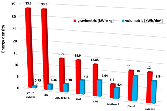
Figure 1.
Gravimetric and volumetric energy density of selected motor fuels [6].
The weight and volume of the storage system based on each of the above technologies will depend on the expected mileage of the vehicle. To ensure a mileage of 400 km, the mass of the stored hydrogen should be [7]:
- For a passenger car powered by an internal combustion engine, 8 kg of hydrogen, and in the case of using a fuel cell, 4 kg;
- For a truck, 32 kg and 16 kg, respectively;
- For a bus, 41 kg and 20 kg, respectively.
Vehicle manufacturers impose a number of requirements on tanks intended for hydrogen storage, not only regarding strength parameters specified in standards and regulations but also in terms of expecting the tanks to be characterized by favorable operational parameters, i.e., satisfactory gravimetric and volumetric energy density of the energy storage system.
The mass of hydrogen per unit volume (kgH2/m3) at 25 °C can be calculated using a simple formula as 0.0807 × p. This formula is derived from the ideal gas equations, where p denotes the hydrogen storage pressure in bar. For example, for a pressure p = 35 MPa, the mass of stored hydrogen is 28 kgH2/m3 [8]. Considering that 5 kg of hydrogen are needed to provide a light vehicle with a range of 400 to 600 km, the tank should have a capacity of 0.18 m3 [6]. The energy storage efficiency of compressed hydrogen is about 94% and can be compared to the energy storage efficiency of batteries, which is 75% [9].
It should be noted that increasing the hydrogen pressure increases the volumetric storage density (kgH2/m3) but reduces the overall energy efficiency. Moreover, doubling the pressure increases the stored energy by only 40–50%. Type 1 steel tanks have been widely used for storing compressed hydrogen for many years, but steel is not a desirable material for these applications. The penetration and accumulation of hydrogen atoms inside the metal contributes to the formation of so-called “hydrogen embrittlement,” a group of corrosive phenomena that negatively affect the operation process. Also due to the excessive weight of steel tanks, tanks for storing compressed hydrogen in modern motor vehicles are mainly types 3 and 4. The main parameters taken into account when considering hydrogen storage in automotive pressure tanks are the type of vehicle, tank capacity, pressure of the stored hydrogen, and the price of the tank. Compressed hydrogen is stored in a closed system, which means that hydrogen can be stored without loss for a long time, provided that the materials used prevent hydrogen diffusion. The cylindrical shape of currently used pressure tanks results primarily from the favorable stress distribution and the recommended and operationally proven starting materials for their production. Designers strive to develop tanks whose form will be adapted to the spatial possibilities created by the structure of the vehicle chassis or body. New materials and technologies make it possible to produce nanocomposite layers that are characterized by very low hydrogen permeability (0.6 cm3µm/m2day) [10]. These extremely efficient nanocomposite barrier layers are obtained, among others, by spray coating liquid crystalline nanosilicates mixed with polyvinyl alcohol (PVA) on a PET substrate film. The technology of refining the lining surface by spraying allows for the creation of a barrier limiting the permeability of hydrogen in tanks of irregular shape.
Hydrogen compression is the most popular and common method of storing H2 [11]. The significant advantage of storing hydrogen as a gas at high pressure is the high release rate and fast filling. Although this technology is simple, its main disadvantages are safety issues and storage space requirements. High-pressure storage at an NWP of up to 700 bar is crucial for increasing the range of vehicles. Due to weight requirements in automotive applications, type IV pressure vessels with a thermoplastic liner and a surrounding fiber-reinforced composite have been developed. The thermoplastic liner provides a suitably low hydrogen permeation coefficient. In addition, the composite can withstand mechanical stresses caused by high internal pressure.
The main disadvantage of the composite material is its sensitivity to fire. When subjected to external thermal load, the composite wall starts to degenerate, thereby losing its mechanical strength [12,13,14]. This process continues through the material until the effective wall thickness reaches a critical level. At this point, the vessel will burst if the internal pressure cannot be reduced by means of a thermal protection installed on the tank [15,16].
Immediate hydrogen ignition usually causes hydrogen jet fires, while delayed hydrogen ignition leads to an explosion, which is the result of deflagration and/or detonation. There is therefore both a direct and an indirect threat to people and the environment. The effects of these accidents, including a jet of fire, thermal radiation, and, in the worst case, a tank explosion and the resulting shock wave, require that the safety aspects of hydrogen storage be taken into account in the tank design process [17]. This condition is essential for the reliable, safe, and efficient use of hydrogen as a source of clean energy for automotive vehicles. Polymers and resins are much more susceptible to high temperatures than metal materials. Therefore, the maximum operating temperature is a matter of the safety of their use, and as a consequence, the assessment of the composite’s behavior in fire and the fire protection mechanism is extremely important, especially in on-board applications. The assessment of the CHSS’s performance in fire conditions is carried out during a fire test. Its positive result determines the CHSS’s acceptance for use. However, it should be emphasized that the fire test is more a qualification test, comparing and evaluating different tank designs, than a guarantee of ensuring operational safety, which is a broader issue.
In the CHSS homologation process, test procedures are used to meet the requirements specified in the applicable legislative acts, but tests are also conducted that go beyond their conditions [18]. Their purpose is to provide detailed information in non-standard situations. The results of these tests allow for verification and then updating of the applicable regulations [19]. The fire test procedure is specified in the proposal for the 02 series of amendments to UN Regulation No. 134, which was established as the basis for a global standard for the approval/certification of hydrogen fuel systems. This document recommends that not only the temperature but also the HRR of the fire source should be monitored during the fire test. Monitoring these parameters should help improve the repeatability of the fire test in different laboratories. In addition, this version of the regulation recommends conducting a pre-test, which allows not only the characterization of the test stand, but also the correct operation of all measuring devices.
2. Materials and Methods
Testing the fire resistance of the tank is one of the final stages of the approval/certification process. The purpose of the test is to check the correct operation of the safety equipment and the strength of the tank under working pressure, under conditions of open flame. The test was provided on the basis of the requirements in the regulation [20]. The pre-test checkout aims to verify that the localized and engulfing burner zones are operating as expected and that the test setup, including windshields, is functional and capable of delivering repeatable results before conducting the CHSS main fire tests.
2.1. Test Stand
The burner prepared for testing was made in accordance with specific recommendations [21]. Its dimensions are listed in Table 1 and Table 2, and the complete burner is presented in Figure 2 and Figure 3.

Table 1.
Definition of burner nozzles for the prescribed burner.
Table 2.
Burner dimensions and surfaces of localized and engulfing fire zones.
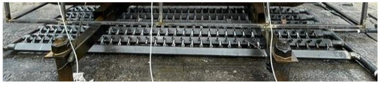
Figure 2.
View of the burner on the longitudinal axis.

Figure 3.
View of the burner on the transverse axis.
According to the cylinder definition [21], a 320 mm-diameter cylinder, similar to that used in vehicle fire tests, should be used for the initial burner test. The cylinder length must be at least 800 mm and the total length should not exceed the maximum length of the engulfing burner. A 320 mm-diameter and 1600 mm-long chrome molybdenum steel cylinder was used in the presented test. The location of the cylinder in relation to the burner is shown in Figure 4. The stand supports ensure the required distance of the lower wall of the cylinder from the burner. The required position of the thermocouples measuring the flame temperature is ensured by special brackets integrated with the burner. The arrangement of thermocouples on the stand is shown in Figure 5. The marking of thermocouples and their arrangement at all measuring points on the truss (Figure 6) was performed in accordance with the recommended requirements [21].
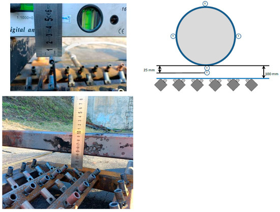
Figure 4.
Location of the cross-steel bar on which the cylinder will lie and the thermocouples for flame measurement relative to the burner.
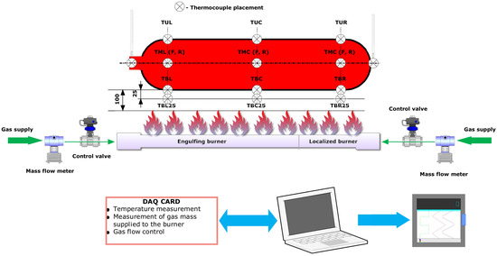
Figure 5.
Schematic diagram of the station, including the arrangement of the thermocouples.
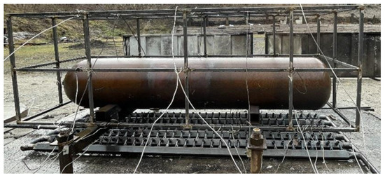
Figure 6.
Tank on the pre-test stand with a truss holding the thermocouples.
2.2. Pre-Test Procedure
The test consists of two stages: a localized fire stage followed by an engulfing stage, as described in Figure 7. In the first one, a limited, localized fire affects the tank. After 10 min, an additional burner is turned on, providing an engulfing fire.
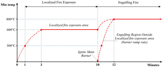
Figure 7.
Base flame temperature profile during the fire test.
The test procedure consisted of the following steps:
- The steel cylinder was placed horizontally so its lower surface was 100 ± 5 mm above the fire source. Then, all the thermocouples were placed, as shown in Figure 8. The thermocouple system was mechanically supported to prevent the thermocouples from changing position during temperature measurement.
- Wind shields were used.
- The rate of fuel flow to the localized and engulfing fire source was determined to obtain the recommended values of heat release by the fire source per unit area (HRR/A). The required flow rate was calculated according to the following formula:HRR/A = (H × Q)/A,where HRR/A is heat release rate per unit area of the fire source, expressed in kilowatts per square meter (kW/m2); H is the lower heating value of the fuel, expressed in megajoules per kilogram (MJ/kg); Q is the fuel flow rate, expressed in grams per second (g/s); and A is the area of the fire source, expressed in square meters (m2). The supply gas is propane.To obtain the recommended HRR/A value [21]:
- For a localized flame of 300 kW/m2, a gas mass flow of 0.85 g/s was used.
- For an engulfing flame of 700 kW/m2, a gas mass flow of 10.6 g/s was used.
- Pre-test duration: 1020 s, including the localized fire phase of 10 min and the engulfing fire phase of 418 s.
- The gas mass flow to the localized burner was constant throughout the test. The gas flow to the engulfing burner began 10 min after the test started and was maintained at the required value until the test was completed.
- Signals from mass flow meters were recorded. During the test, thermocouple temperature data were recorded, and then the 60 s rolling average was calculated.
3. Results
3.1. Measuring Temperatures at Specific Points
The purpose of the pre-test is to verify that the localized and engulfing burner zones provide the required amount of energy during tests performed on tanks filled with hydrogen to 100% and that the test stand configuration (with a wind shield) is functional and allows for the provision of repeatable results. The pre-test must be repeated each time any of the stand elements affecting the thermal parameters of the heat flow supplied to the tank have been changed. Figure 8 shows the results of the required temperature measurements in the localized fire phase. The image on the left shows the area affected by the flame in this test phase. Figure 9 refers to the engulfing fire phase. In this phase, the second burner is started 10 min after the start of the test. Then, the entire tank is exposed to the fire, or a 1.65 m section if the tank is longer than the burner.
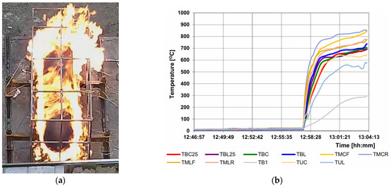
Figure 9.
Test progress in the engulfing fire phase: (a) flame impact zone on the tank; (b) measurement results of the selected thermocouples, important for this stage.
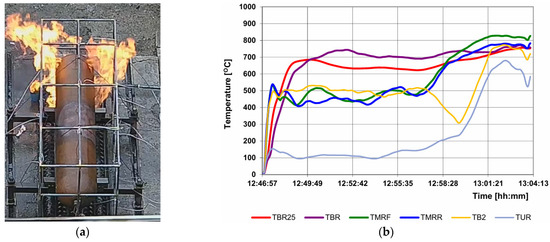
Figure 8.
Test progress in the localized fire phase: (a) flame impact zone on the tank; (b) measurement results of the selected thermocouples, important for this stage.
3.2. Measurement of the Fuel Flow Feeding the Burners
During the pre-test, the basic control parameter is the amount of gas supplying the burners in the individual stages. The basis for the control are the values suggested in the R134 regulation. The range of changes in the gas flow rate was calculated so that each of the burners would provide the required heating power. The gas flow to the burners is continuously monitored during the test. The measurement was performed separately for each burner by flow meters installed at the outlet of the collectors supplying the burners. The recorded results are presented in the graph (Figure 10). In assessing the correctness of control, the average value of the gas mass flow is taken into account (Figure 11).
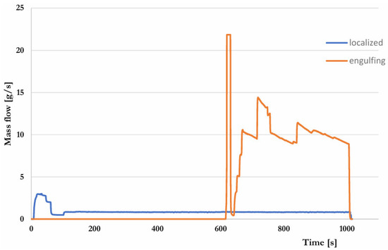
Figure 10.
Course of the mass gas flow to both burners.
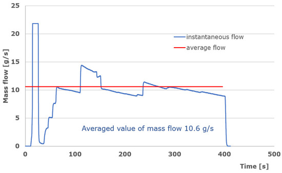
Figure 11.
Course of gas flow to the engulfing burner.
4. Discussion
4.1. Verification of Required Temperature Parameters
Based on the temperature values measured at selected points, compliance with the requirements presented in R134 should be checked. For this purpose, the beginning and end of each test stage should be precisely marked on the time axis, as shown in Figure 12 and Figure 13. Next, specific temperature parameters were calculated. The guidelines for their calculation are as follows:
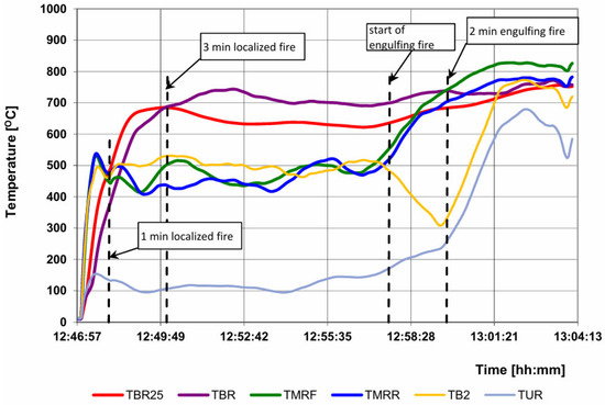
Figure 12.
Temperature courses in the area of the burner of a localized fire and division into the required pre-test phases.
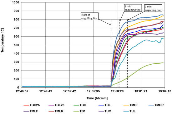
Figure 13.
Temperature courses in the area of the burner of an engulfing fire and division into the required pre-test phases.
- TBLOC is the bottom surface temperature of the pre-test cylinder based on TBR.
- TMFLOC is the surface temperature of the front side of the pre-test cylinder based on TMRF.
- TMRLOC is the surface temperature of the rear side of the pre-test cylinder based on TMRR.
- TULOC is the top surface temperature of the pre-test cylinder based on TUR.
- TBLOC25 is the burner monitor below the pre-test cylinder based on TBR25. Thermocouples used to back up or supplement TBR25 may also be included in the calculation of the average temperature of the burner monitors in the localized fire zone.
- TBENG is the bottom surface temperature of the pre-test cylinder based on the average of TBR, TBC, or TBL within the engulfing fire zone.
- TMFENG is the surface temperature of the front side of the pre-test cylinder based on the average of the TMLF, TMCF, and TMRF within the engulfing fire zone.
- TMRENG is the surface temperature of the rear side of the pre-test cylinder based on the average of the TMLR, TMCR, and TMRR within the engulfing fire zone.
- TUENG is the top surface temperature of the pre-test cylinder based on the average of the TUR, TUC, or TUL within the engulfing fire zone.
- TBENG25 is the burner monitor below the pre-test based on the average of the three required thermocouples (TBR25, TBC25, or TBL25 for the pre-test checkout) within the engulfing fire zone. Thermocouples used to back up or supplement the TBR25, TBC25, or TBL25 may also be in included in the calculation of the average temperature of the burner monitor in the engulfing fire zone.
The calculated temperature parameters are shown in Figure 14. Based on the calculation results, compliance with the requirements was checked. The criteria and results are presented in Table 3. In the last stage of the results development, monitoring indicators were determined, which will be used to verify the actual fire resistance tests.
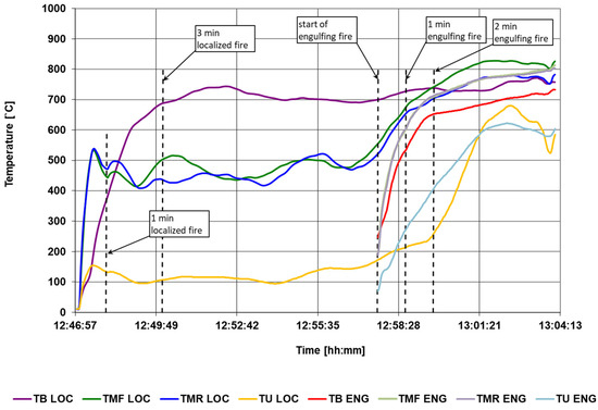
Figure 14.
The calculated temperature parameters.
Table 3.
Criteria for acceptance of localized and engulfing burner configurations [21].
The verification of the required temperature parameters is satisfactory because the calculated values meet all the requirements specified in the regulations. This proves that the burners and wind shields are properly configured.
4.2. Establishing Temperature Monitors
Additionally, burner monitors should be designated at the established localized and engulfing burner. The monitor values will be control indicators during the performance of fire tests on hydrogen-filled tanks. Achieving the monitor value in both test stages is necessary to recognize the correctness of the test. If the monitor is not achieved within the specified time, the test should be stopped and repeated after verifying the correctness of the burner power supply and sealing the wind shields at the stand. Temperature monitors are defined as follows:
- The minimum value for the burner monitor during the localized fire stage (TminLOC25) shall be calculated by subtracting 50 °C from the 60 s rolling average of the TBLOC25. If the resultant minimum values exceed 600 °C, the minimum value is set to 600 °C for the localized fire stage.
- The minimum value for the burner monitor during the engulfing fire stage (TminENG25) shall be calculated by subtracting 50 °C from the 60 s rolling average of the TBENG25. If the resultant minimum values exceed 800 °C, the minimum value is set to 800 °C for the engulfing fire stage.
Figure 15 shows the parameters that are the basis for determining the monitors. In the localized fire phase, the monitor is checked after 3 min, and in the surrounding fire phase after 2 min from the start of the stage.
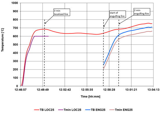
Figure 15.
Calculated temperature monitor control values.
Taking the above into account, the established monitors are:
TminLOC25 = 600 °C,
TminENG25 = 565 °C.
4.3. Calculation of the Amount of Heat Released by the Burners
Based on the recorded gas consumption during the pre-test, the unit power of the burners can be calculated. Referring to the range of HRR/A, as suggested in the regulations, the mass of the gas stream supplying the burners is also determined. The values obtained are also guidelines for controlling the gas supply to the burners during fire tests during hydrogen tank tests. The HRR/A values for both phases of the pre-test are within the recommended range to meet the established acceptance criteria (Table 4).
Table 4.
The range of proposed and actual burner power settings.
5. Conclusions
Fire resistance tests are used as a method of verifying the design/materials of the tank and the correct operation of safety devices. Their continuous development is reflected in the improvement in homologation tests. The fire resistance test procedure proposed in the 02 series places great emphasis on the unification of the fire source. The purpose of the changes introduced is to ensure repeatability of conditions during real tests.
The results obtained confirm that the stand prepared for the pre-test ensures compliance with the requirements contained in the proposal for the 02 series of amendments to UN Regulation No. 134. The burner described above should ensure the repeatability of each fire test carried out on the tested hydrogen tanks.
Author Contributions
Conceptualization, G.K. and M.F.; methodology, G.K., M.F., P.F. and P.M.; software, P.M. and P.H.; formal analysis, G.K. and M.F.; investigation, G.K., M.F., P.F., P.M. and P.H.; resources, G.K., P.M. and P.H.; data curation, G.K., P.F. and P.M.; writing—original draft preparation, G.K., M.F. and P.M.; writing—review and editing, G.K., M.F. and P.M.; visualization, G.K., M.F. and P.M.; supervision, G.K. All authors have read and agreed to the published version of the manuscript.
Funding
The Article Processing Charge was financed under the European Funds for Silesia 2021–2027 Program co-financed by the Just Transition Fund—project entitled “Supporting the staff in intensifying scientific activities in the field of transport transformation towards a green and digital economy”. Project number: FESL.10.25-IZ.01-03AF/23-00; Project number at the Silesian University of Technology: 12/010/FSD24/1161.
Data Availability Statement
The raw data supporting the conclusions of this article will be made available by the authors on request.
Conflicts of Interest
The authors declare no conflict of interest.
Abbreviations
The following abbreviations are used in this manuscript:
| CGH2 | Compressed gaseous hydrogen |
| CHSS | Compressed hydrogen storage systems |
| FC | Fuel cells |
| HRR/A | Heat release rate per unit area of the fire source |
| ICE | Internal combustion engine |
| LH2 | Liquid hydrogen |
| NWP | Nominal working pressure |
References
- Molkov, V. Fundamentals of Hydrogen Safety Engineering I; BookBoon: London, UK, 2012; ISBN 978-87-403-02226-4. [Google Scholar]
- Molkov, V. Fundamentals of Hydrogen Safety Engineering II; BookBoon: London, UK, 2012; ISBN 978-87-403-0279-0. [Google Scholar]
- Kovacs, D.; Rezaei, R.; Englert, F.; Hayduk, C.; Delebinski, T. High Efficiency HD Hydrogen Combustion Engines: Improvement Potentials for Future Regulations. SAE Tech. Pap. 2022, 1, 477. [Google Scholar] [CrossRef]
- Lohse-Busch, H.; Stutenberg, K.; Duoba, M.; Liu, X.; Elgowainy, A.; Wang, M.; Wallner, T.; Richard, B.; Christenson, M. Automotive fuel cell stack and system efficiency and fuel consumption based on vehicle testing on a chassis dynamometer at minus 18 °C to positive 35 °C temperatures. Int. J. Hydrogen Energy 2020, 45, 861–872. [Google Scholar] [CrossRef]
- Hosseini, S.E.; Butler, B. An overview of development and challenges in hydrogen-powered vehicles. Int. J. Green Energy 2020, 17, 13–37. [Google Scholar] [CrossRef]
- Japan DME Forum. DME Handbook [English Edition]; Japan DME Forum (current Japan DME Association): Tokyo, Japan, 2007. [Google Scholar]
- NOW GmbH. Available online: https://www.now-gmbh.de/foerderung/ (accessed on 30 June 2023).
- Leung, M.K.H.; Leung, D.Y.C.; Sumathy, K.; Ni, M. Feasibility Study of Renewable Hydrogen in Hong Kong; HKSAR: Hong Kong, 2004. [Google Scholar]
- Chan, R.W.M. Feasibility Study on Hydrogen Storage with Intermittent Renewables on Island–Case Study of the Canary Islands. Master’s Thesis, University of London, London, UK, 2000. [Google Scholar]
- Habel, C.; Tsurko, E.S.; Timmins, R.L.; Hutschreuther, J.; Kunz, R.; Schuchardt, D.D.; Rosenfeldt, S.; Altstädt, V.; Breu, J. Lightweight Ultra-High-Barrier Liners for Helium and Hydrogen. ACS Nano 2020, 14, 7018–7024. [Google Scholar] [CrossRef] [PubMed]
- Durbin, D.J.; Malardier-Jugroot, C. Review of hydrogen storage techniques for on board vehicle applications. Int. J. Hydrogen Energy 2013, 38, 14595–14617. [Google Scholar] [CrossRef]
- Mori, D.; Hirose, K. Recent challenges of hydrogen storage technologies for fuel cell vehicles. Int. J. Hydrogen Energy 2008, 34, 4569–4574. [Google Scholar] [CrossRef]
- Yamashita, A.; Kondo, M.; Goto, S.; Ogami, N. Development of High-Pressure Hydrogen Storage System for the Toyota “Mirai”. SAE Tech. Pap. 2015, 1, 1169. [Google Scholar] [CrossRef]
- Abohamzeh, E.; Salehi, F.; Sheikholeslami, M.; Abbassi, R.; Khan, F. Review of hydrogen safety during storage, transmission, and application processes. J. Loss Prev. Process Ind. 2021, 72, 104569. [Google Scholar] [CrossRef]
- Moradi, R.; Groth, K.M. Hydrogen storage and delivery: Review of the state of the art technologies and risk and reliability analysis. Int. J. Hydrogen Energy 2019, 44, 12254–12269. [Google Scholar] [CrossRef]
- Rivard, E.; Trudeau, M.; Zaghib, K. Hydrogen Storage for Mobility: A Review. Materials 2019, 12, 1973. [Google Scholar] [CrossRef] [PubMed]
- Hupp, N.; Stahl, U.; Kunze, K.; Wilde, P.; Sinske, H.; Hinrichsen, O. Influence of fire intensity, fire impingement area and internal pressure on the fire resistance of composite pressure vessels for the storage of hydrogen in automobile applications. Fire Saf. J. 2019, 104, 1–7. [Google Scholar] [CrossRef]
- Molkov, V.; Kashkarov, S.; Makarov, D.; Fletcher, J.; Rattigan, W. Explosion free in fire self-venting (TPRD-less) Type IV tanks: Validation under extreme impinging 70 MPa hydrogen jet fire conditions. Int. J. Hydrogen Energy 2023, 48, 40117–40126. [Google Scholar] [CrossRef]
- Molkov, V.; Kashkarov, S.; Makarov, D. Explosion free in fire self-venting (TPRD-less) composite tanks: Performance during fire intervention. Int. J. Hydrogen Energy 2024, 50, 804–814. [Google Scholar] [CrossRef]
- European Union. Regulation No 134 The United Nations Economic Commission for Europe (UNECE)—Uniform Provisions Concerning the Approval of Motor Vehicles and Their Components with Regard to the Safety-Related Performance of Hydrogen-Fuelled Vehicles (HFCV)—Supplement 03 to the Original Version of the Regulation; European Union: Geneva, Switzerland, 2019. [Google Scholar]
- UN Economic Commission for Europe. (IWG on HFCV) Proposal for Amendment 1 to UN Global Technical Regulation No. 13. Phase 2 (Hydrogen and Fuel Cell Vehicles); UN Economic Commission for Europe: Geneva, Switzerland, 2023. [Google Scholar]
Disclaimer/Publisher’s Note: The statements, opinions and data contained in all publications are solely those of the individual author(s) and contributor(s) and not of MDPI and/or the editor(s). MDPI and/or the editor(s) disclaim responsibility for any injury to people or property resulting from any ideas, methods, instructions or products referred to in the content. |
© 2025 by the authors. Licensee MDPI, Basel, Switzerland. This article is an open access article distributed under the terms and conditions of the Creative Commons Attribution (CC BY) license (https://creativecommons.org/licenses/by/4.0/).