1. Introduction
Energy-intensive industries like metal, glass, or paper manufacturers use impingements jets to efficiently heat or cool products, where highly efficient nozzle systems are essential to minimise energy consumption [
1]. Climate protection and resource efficiency are key issues in society and politics. Innovative and resource-efficient lightweight construction solutions are needed to reduce emissions and achieve our climate, sustainability, and electromobility goals [
2]. High-strength aluminium and steel alloys are important factors for lightweight automotive construction. An amount of 100 kg less weight reduces the fuel consumption of a car by 0.7 l per 100 km. For electric vehicles a weight reduction is reflected in increased range. [
3]. The materials optimised for these properties are characterised by demanding production routes, especially in terms of heat treatment. The complex requirements for the material properties place high demands on the nozzle systems. It is therefore imperative to continuously improve highly efficient nozzle systems for various applications across all industries.
Despite many studies [
4] that have been carried out on impingement jets, further research is needed to optimise nozzle systems for specific applications with high Reynolds numbers
Re > 10,000 due to the complex flow characteristics of impingement jets when striking a surface (see
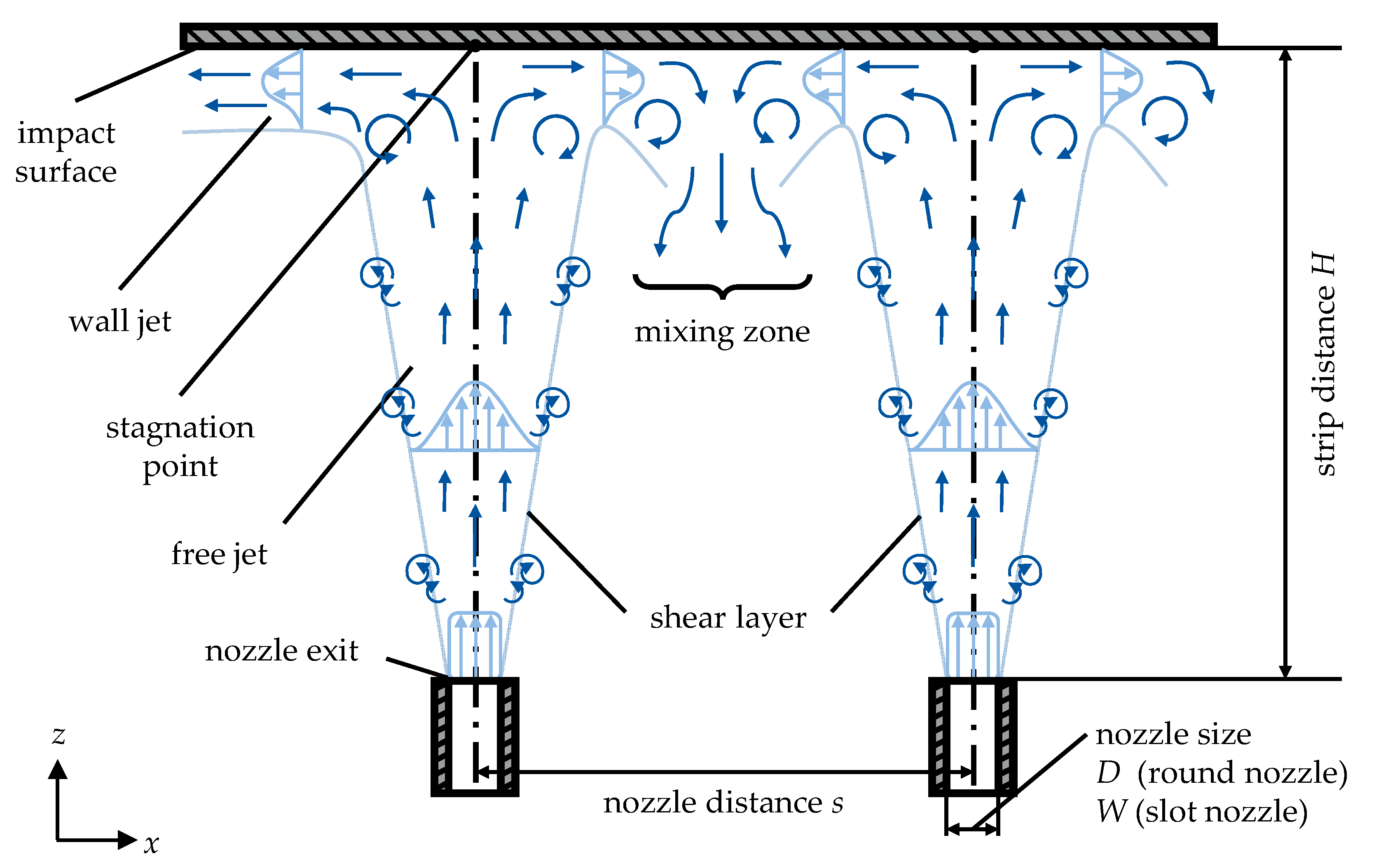
Figure 1). In this work, an industrial nozzle system used in the heat treatment of metal strips is analysed. The original nozzle array can be analysed without simplifications. An impingement jet can be divided into three zones: free jet zone, stagnation zone, and wall jet zone. For nozzle arrays an additional mixing zone is taken into consideration [
5,
6].
Starting from the nozzle, a free jet is formed which continuously expands and mixes with the surrounding medium (shear layer). As a result, the vertical velocity component decreases continuously until it is reduced to zero at the stagnation point. At the same time, the horizontal velocity component increases and a wall jet zone is formed. The area between individual nozzles in a nozzle field is referred to as a mixing zone. The characteristics of this flow depend on the nozzle geometry (round nozzle: nozzle diameter D, slot nozzle: slot width W), the distance between the nozzle outlet and the impact surface (strip distance H), the nozzle exit velocity u, and, in the case of a nozzle array, the distance between the individual nozzles s. In addition, the flow and therefore the heat transfer is very sensitive to the nozzle arrangement. A low ratio of strip distance to nozzle size is aimed for to maximise heat transfer but is not always technically feasible.
Within the free jet, the potential core jet is of importance for heat transfer. Here, the velocity remains constant and is equal to the nozzle exit velocity. The length of the core jet depends on the degree of turbulence of the nozzle flow and the nozzle exit velocity. The potential core jet length is defined as the position where the mean flow dynamic pressure (proportional to speed squared) reaches 95% of the initial value at the nozzle exit. For slot nozzles, the core jet length is between 4.7 and 7.7 times the nozzle width [
7,
8].
The basis for optimising nozzle systems is a sufficient understanding of the flow. The challenge is to visualise the real flows and their properties such as velocity and direction. One way to build up this understanding is through experiments supported by particle-based optical measurement techniques for describing velocities in flows. These include Laser Doppler Anemometry (LDA), Particle Image Velocimetry (PIV), Doppler Global Velocimetry (DGV), and Laser Transit Velocimetry (LTV) [
9]. PIV’s ability to capture the flow velocity of a large number of points in an area simultaneously, the possibility for quantitative visualisation of flow structures, and gradient-based variables such as vorticity have led PIV to be used in various nozzle systems before [
10]. Due to the wide range of applications of impingement jets, various optical flow investigations which have been carried out are summarised in
Table 1.
Different types of nozzles and settings have been studied, including single nozzles and nozzle arrays with different shapes. The focus of the studies is also varied, e.g., Barbosa et al. [
19,
20] investigate the influence of the impact plate shape. Only a few studies deal with flows
Re > 10,000, resulting in a specific field of research for highly convective heat transfer, which is characterised by very high flow velocities and special nozzle systems. In addition, often only individual nozzles are investigated, leaving the transferability of results to entire nozzle arrays limited. Especially for slot nozzle arrays, there is little data availability.
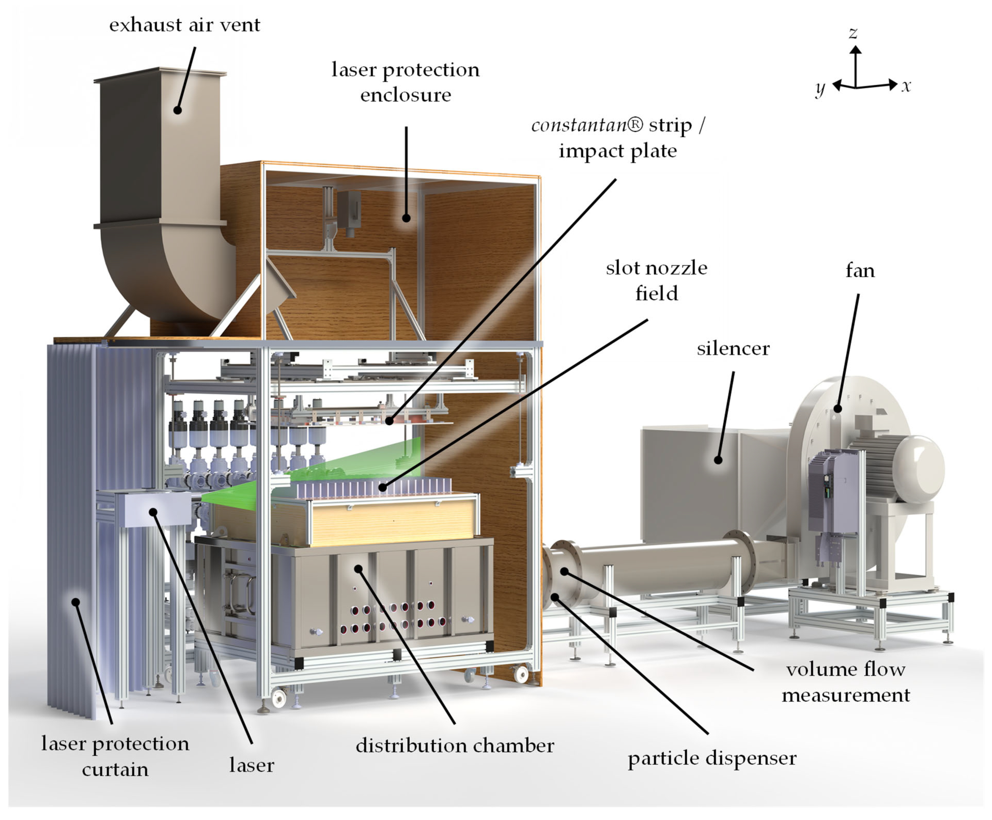
The aim of this study is to fill this research gap by investigating highly convective air flows at Re = 10,000 to Re = 50,000 using PIV. The experiments are carried out on a single slot nozzle and on an array of slot nozzles. In particular, the visualisation of the flow in entire slot nozzle arrays on an industrial scale in thermal process technology is unique.
3. Results
The velocity and the turbulent kinetic energy (TKE)
k distributions are determined for each case from the vector fields of the PIV measurements. While the velocity is derived directly from the vector displacement of the particle motion, the turbulent kinetic energy is calculated based on the Reynolds stress
Rxx and
Ryy according to Equation (4).
Since a 2D planar PIV system is used in the present study, the turbulent kinetic energy can only be calculated in the laser slice plane with the vector components
Vx and
Vy. It is assumed that the turbulent kinetic energy in the third not-measured dimension
Vz has the same dimension as
Vx and
Vy [
25]. Turbulent kinetic energy characterises the energy in the fluctuating velocity field and can therefore be understood as a measure of the energy content of the turbulent motion in a flow. Since it is well known that heat transfer increases with increasing turbulence, knowledge of the distribution of turbulent kinetic energy is an important contribution for the optimisation of nozzle systems [
26].
The singe-slot nozzle was measured within a range from x = ± 40 mm. The measurement of the slot nozzle array focused on the middle three nozzles (x = ± 90 mm). This allows the influence of increasing nozzle exit velocities on the formation of flow structures to be analysed. In addition, for the slot nozzle array, the interaction between the nozzles can be evaluated. To ensure a visual comparison of the data between the results of the single slot nozzle and the slot nozzle array, the scales per nozzle exit velocity have been kept the same. However, it should be noted that the TKE values of the slot nozzle array exceed the maximum value of the scale. Adjusting the scales to present the results of the single slot nozzle would result in a significant loss of information. This also applies to standardised scaling over the velocities.
3.1. Single Slot Nozzle
Initially, the flow through a single slot nozzle with a strip distance of
H = 50 mm is analysed at different nozzle exit velocities.
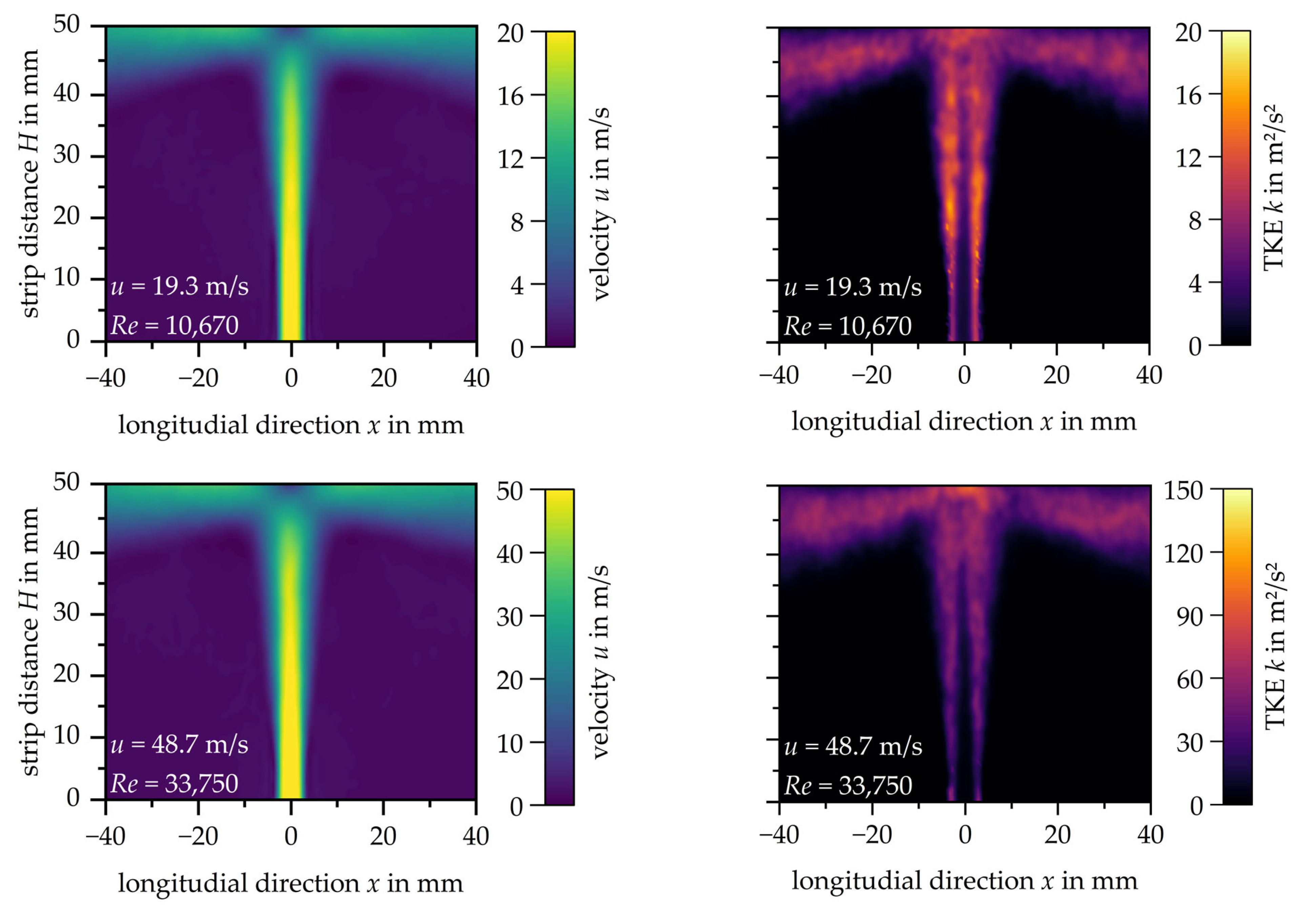
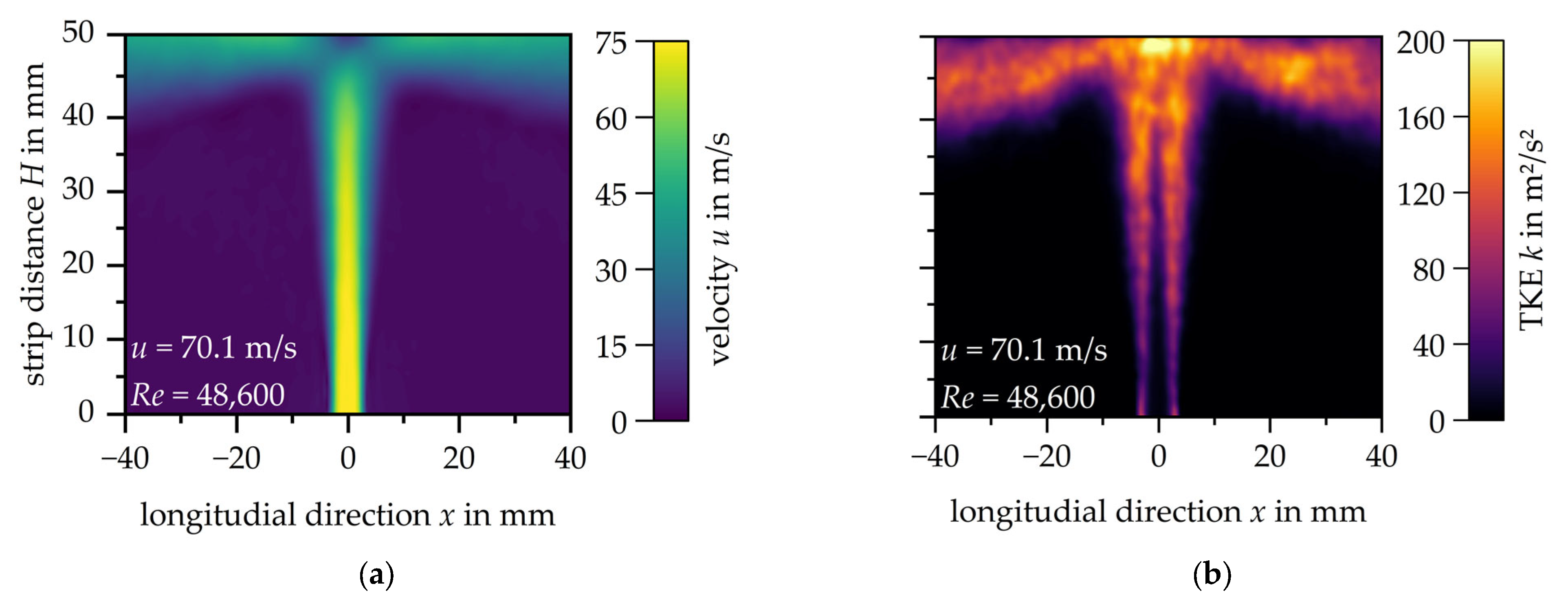
Figure 4a shows the velocity distributions for the three different exit velocities, while
Figure 4b illustrates the corresponding distributions of turbulent kinetic energy. Note that the scales had to be adapted to the increasing exit velocity. A uniform scaling across all velocities leads to reduced contrast, resulting in reduced readability of the measured data.
The influence of the nozzle exit velocity u on the flow is limited since only higher velocities in both the free jet and the wall jet can be observed. The dimension of the stagnation zone remains unaffected, as does the expansion of the shear layer.
The distribution of turbulent kinetic energy (TKE) throughout the impingement jet changes with increasing nozzle exit velocity. Turbulent kinetic energy is generally lowest in the centre of the free jet and wall region and highest in the shear layers of the free jet and the wall jet. The formation of the impingement jet is symmetrical.
For the lowest nozzle exit velocity of u = 19.3 m/s (Re = 10,670), the highest turbulent kinetic energy of k = 15 m2/s2 is reached in the shear layer of the free jet. The turbulent kinetic energy increases with increasing nozzle exit velocity at u = 48.7 m/s and reaches its maximum at the stagnation point at k = 95 m2/s2. The wall jet reaches a turbulent kinetic energy value up to k = 65 m2/s2. In the shear layer of the free jet a turbulent kinetic energy of k = 40 m2/s2 is reached.
At the maximum investigated nozzle exit velocity u = 70.1 m/s, the turbulent kinetic energy reaches up to k = 200 m2/s2 at the stagnation point. It is noticeable that the zone of increased turbulent kinetic energy in the area of the stagnation point expands as the nozzle exit velocity increases. Analogous to the doubling of the turbulent kinetic energy at the stagnation point of the impingement jet by increasing the nozzle exit velocity from u = 48.7 m/s to u = 70.1 m/s, the turbulent kinetic energy in the wall jet (k = 134 m2/s2) and in the shear zone (k = 89 m2/s2) also doubles.
3.2. Slot Nozzle Array
Single nozzles are not commonly used in an industrial setting; therefore, a slot nozzle array consisting of five single slot nozzles is considered. The flow from the three centre nozzles is evaluated as it is anticipated that the flow formation will repeat symmetrically. The left nozzle appears to be slightly displaced inwards. This, however, does not affect the key findings of the study.
Figure 5a shows the velocity distribution of the slot nozzle array at a nozzle exit velocity of
u = 15.4 m/s.
The impingement jets from each of the three nozzles are clearly visible. The mixing zone between the left and middle nozzle is more pronounced than the mixing zone between the middle and right nozzles. This is also apparent in the distribution of turbulent kinetic energy in
Figure 5b. There are local maxima of
k = 20 m
2/s
2 both in the shear layer of the individual free jets and in the area of the mixing zone where two wall jets meet. The distribution of the turbulent kinetic energy in the individual impingement jet is not symmetrical.
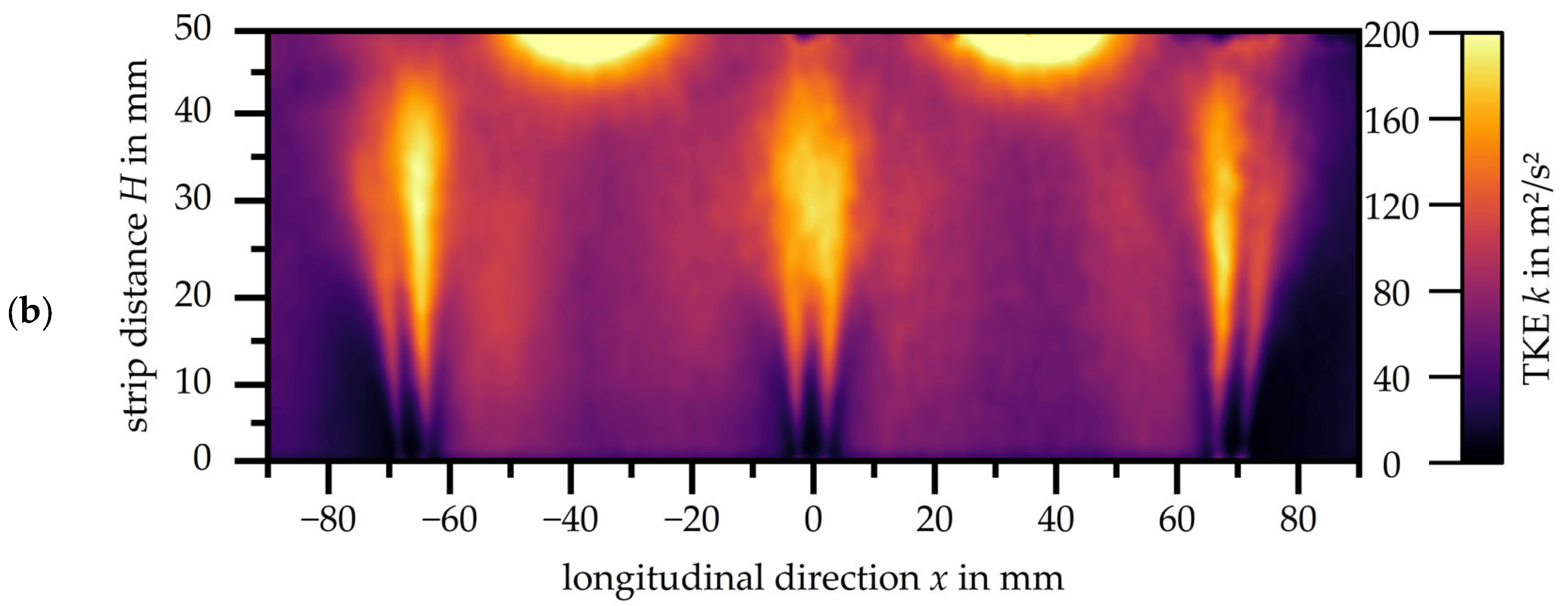
Figure 6 provides in (a) the velocity distribution and in (b) the turbulent kinetic energy distribution of the slot nozzle array with a nozzle exit velocity of
u = 48.7 m/s. Due to the increased nozzle exit velocity, the velocity in the wall jets also increases, resulting in a clearer formation of the wall jet flow and the flow in the mixing zone.
The areas with high turbulent kinetic energy have increased significantly in proportion. After just one third of the free jet, a turbulent kinetic energy of
k = 170 m
2/s
2 is reached in the entire impingement jet. The zone around the interaction between two wall jets has also increased and reaches a turbulent kinetic energy of
k = 200 m
2/s
2. It is now noticeable that the mixing zone extends between the nozzles. There is no change in the flow characteristics when the nozzle exit velocity is increased up to
u = 70.1 m/s in the slot nozzle array (see
Figure 7).
3.3. Uncertainty
The most important criterion for PIV measurements is that the tracer particles follow the flow for any velocity
u without delay. The Stokes number, as shown in Equation (5), is used to verify this criterion. For
Stk << 1 the particles follow the flow closely [
9].
Therefore,
describes the response time as defined in Equation (6) and
is the characteristic time scale of the flow (see Equation (7)) [
24].
The response time formula is valid for
Re < 1. For the velocity range studied,
Re is in the interval of
Re = 10,000 to 50,000 (see
Table 2). Due to the high Reynolds numbers, an additional factor, a standard drag correlation C
D, must be added [
27]. The material data of the DEHS tracer particles (particle diameter
dp, particle density
) were mentioned in
Section 2.2; the dynamic viscosity of the air is specified as
μ = 1.185
10
−5 Pa
s. With the characteristic length of the slot nozzle
L =
Dh = 2
W and the additional factor
CD, this results in
being between 1.86
10
−6 s–1.98
10
−6 s. This leads to Stokes numbers between
Stk = 0.00353–0.01384. Due to the small Stokes numbers for all velocities, the tracing error can be estimated to be less than 1% [
9].
The overall measurement uncertainty is also analysed directly in the software DaVis based on the uncertainty of standard deviation [
25]. According to Wieneke [
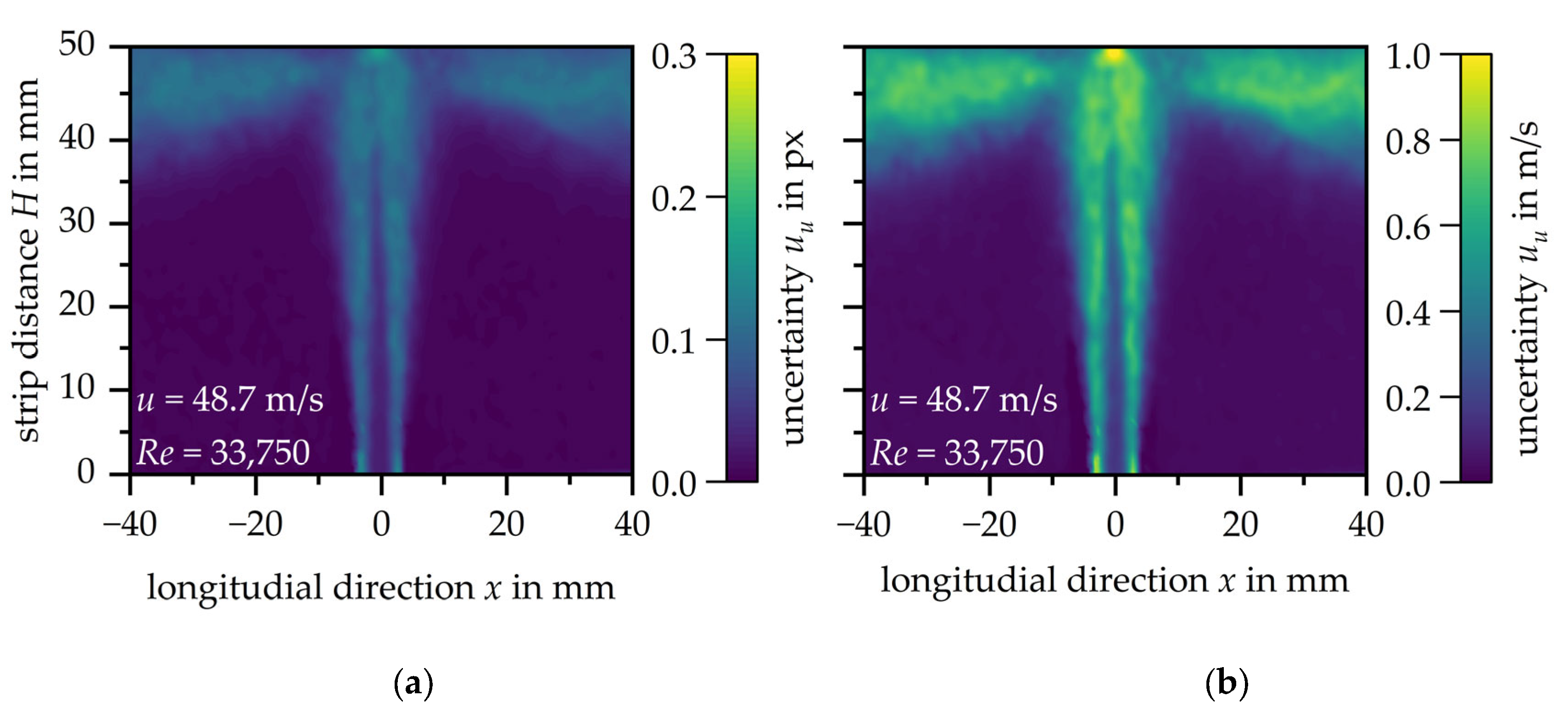
28], a value of 0.01 pixels is considered ‘excellent’ and 0.3 pixels ‘poor’. As an example, the measurement uncertainty is illustrated by the single slot nozzle with a nozzle exit velocity of
u = 48.7 m/s in
Figure 8. The measurement uncertainty of the velocity distribution
uu is shown in pixels in
Figure 8a and in m/s in
Figure 8b. At this point, both units are selected in order to show the accuracies of the PIV measurement carried out in pixels but also the more comprehensible deviation of the velocity distribution in m/s.
The measurement uncertainty of the PIV measurements is on average less than
uu < 0.1 px, except for the stagnation point, where the measurement uncertainty reaches its maximum deviation at
uu = 0.16 px. The illustration in
Figure 8b shows that the corresponding measurement uncertainty is
uu = 0.5 m/s on average and the increased measurement uncertainty at the stagnation point is
uu = 1 m/s.
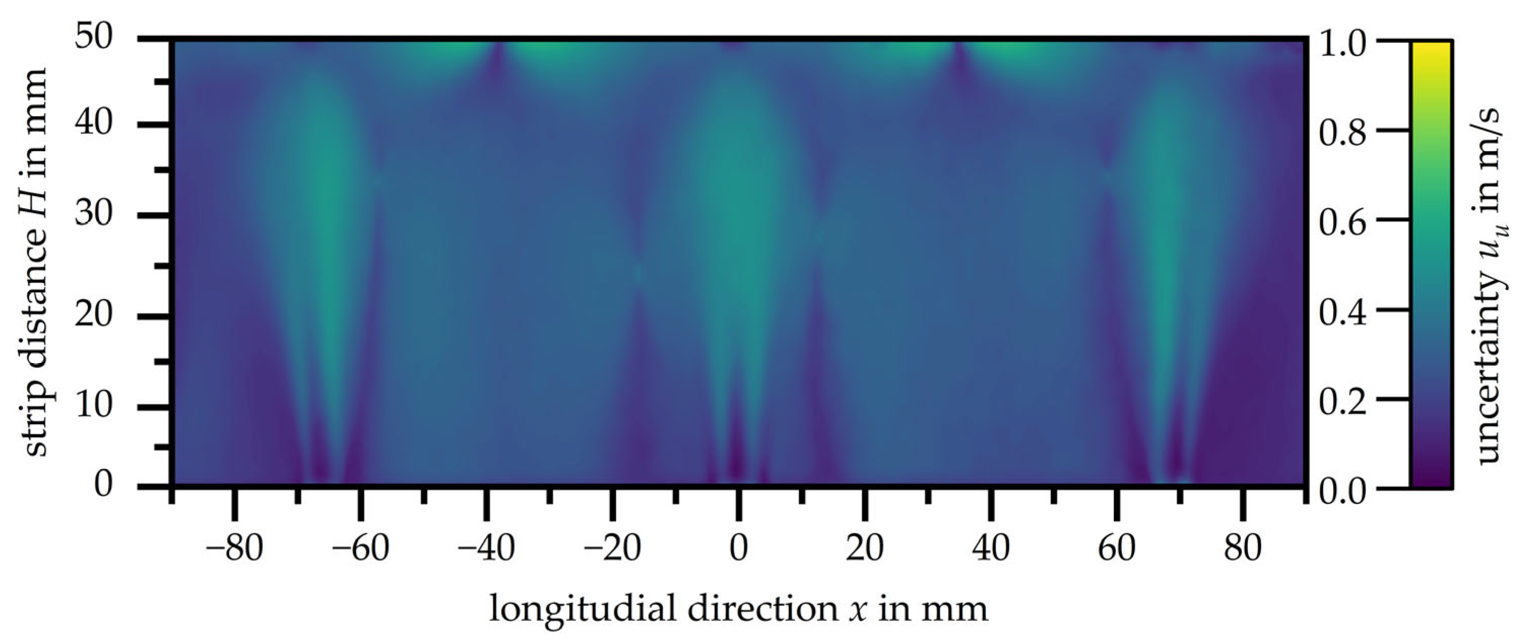
Figure 9 presents the measurement uncertainty
uu of the velocity distribution of the slot nozzle array with a nozzle exit velocity of
u = 48.7 m/s, given in m/s. As with the single nozzle, the accuracy of the PIV in pixels is less than 0.1 px.
The measurement uncertainty of the other investigated nozzle exit velocities are within the shown range and can be considered overall as ’good’ according to Wieneke [
28]. Higher accuracies, especially in the area near the stagnation point, have to be accepted at this point, as the focus is on a comprehensive flow investigation of the impingement jets. A high-resolution analysis of the boundary layer is beyond the scope of this study.
4. Conclusions
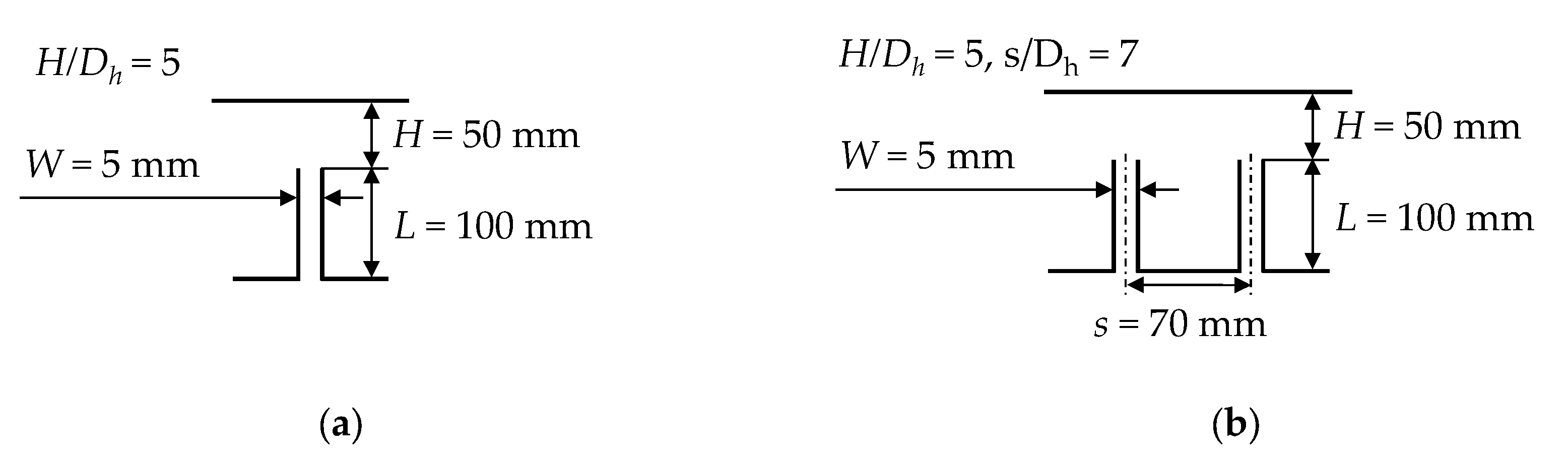
The highly convective flow of an impingement jet generated by a single slot nozzle (W = 5 mm) and a slot nozzle array consisting of five single slot nozzles with a nozzle spacing of s = 70 mm have been investigated for three different nozzle exit velocities. The nozzle exit velocities correspond to Reynolds numbers from approximately Re = 10,000 to 50,000. The resulting flow profiles of the single slot nozzle and the slot nozzle array are subsequently compared and evaluated.
The results for the single slot nozzle show that the formation of the characteristic flow pattern is independent from the nozzle exit velocity leading to an increase in the mean velocity of the impingement jet. The same applies to the turbulent kinetic energy distribution. The turbulent kinetic energy increases reciprocal to the increase in velocity. The same was observed when analysing the slot nozzle array. Furthermore, it can be seen that the velocity in the mixing zone increases with increasing nozzle exit velocity, which leads to a higher turbulent kinetic energy.
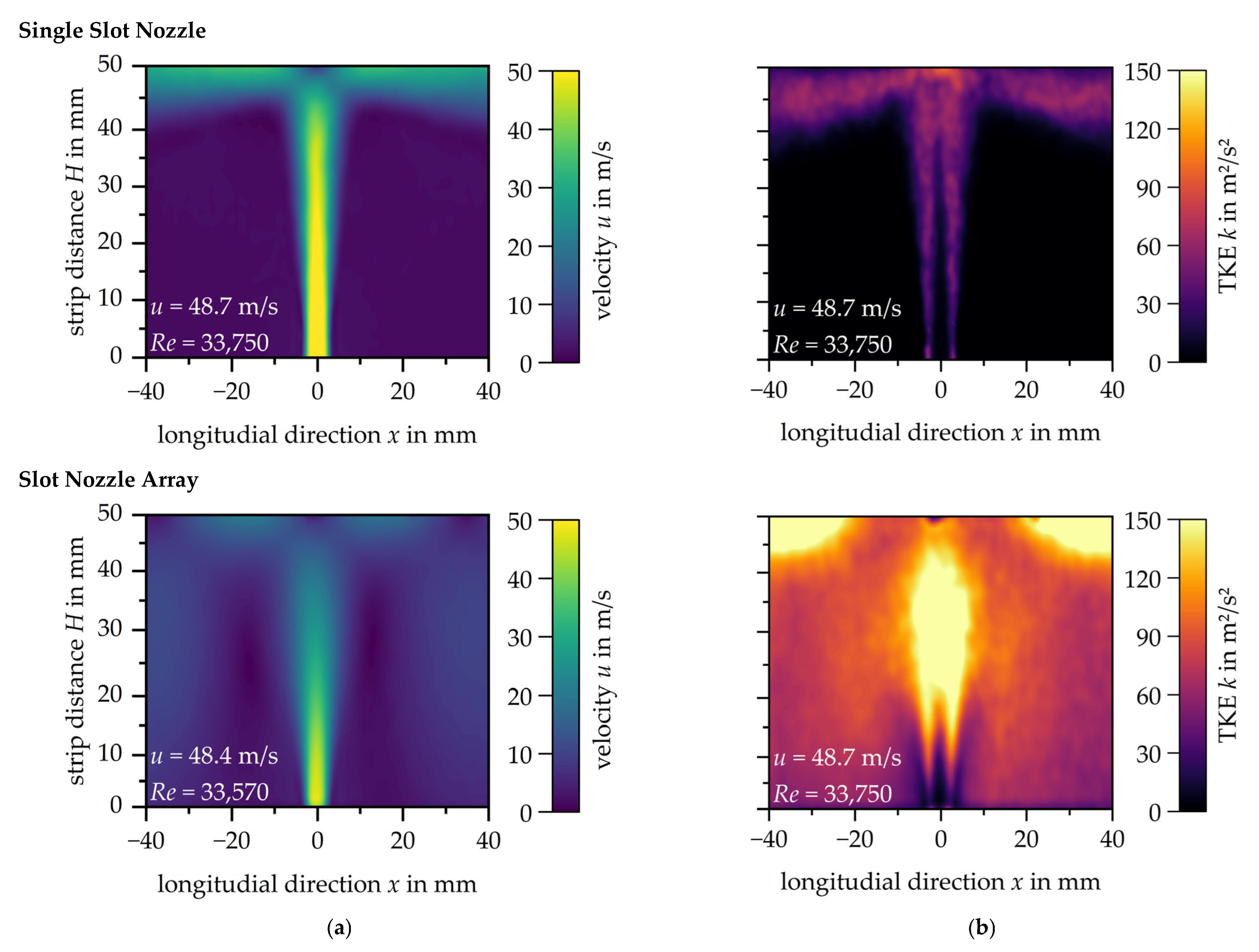
Figure 10 compares the results of the single slot nozzle and the slot nozzle array at a nozzle exit velocity of
u ≈ 48.5 m/s. The central slot nozzle of the slot nozzle array has been selected for this comparison.
Comparison of the velocity profiles at the same nozzle exit velocity shows that the potential core jet length in the free jet of the impingement jet is about one third shorter for the centre nozzle of the slot nozzle array and therefore has a significantly lower velocity.
Table 3 shows the theoretical velocities according to Livingood and Hrycak [
7] for the associated nozzle exit velocities of the single slot nozzle as well as the centre nozzle in the slot nozzle array. The corresponding absolute core jet length and the core jet length as a function of the nozzle width
W from the PIV measurement are also given in the table.
With a relative core jet length of between 6.4 and 6.9, the core jet length of the single slot nozzle is within the range predicted by Zuckermann [
8]. The reduced relative core jet length of 1.3 to 2.8 in the centre nozzle of the slot nozzle array deviates significantly from this specification. In the area between the core jet and the impact surface, a substantial reduction in the velocity of the impingement jet can be recognised.
In the mixing region of the impingement jet a higher velocity is observed due to the interaction with the adjacent jets for the slot nozzle array. The turbulent kinetic energy in the shear layer and in the area of the wall jet where the jets meet is three times higher compared to the single slot nozzle. Even between the nozzles, away from the shear layer, the turbulent kinetic energy is significantly higher. The reverse is observed at the stagnation point. Due to the reduced velocity in the stagnation zone of the slot nozzle array, no local maximum of the turbulent kinetic energy is reached here.
This finding leads to the conclusion that interference between multiple impinging jets is not limited to the mixing zone near the wall. The mixing zone partially extends along the length of the jet, resulting in further interaction with the jet. This leads to a significant reduction in the velocity of each individual impingement jet, but also to a disproportionate increase in turbulent kinetic energy. Geers [
13] made similar observations when analysing single round nozzles and a round nozzle array. The flow in round nozzles is rotationally symmetrical, which is not the case with slot nozzles. Therefore, the results cannot be directly compared to each other. Nevertheless, this work confirms that it is not possible to extrapolate the results of flow investigations on individual nozzles to entire nozzle fields, without compensating for the observed interaction. Further investigations with other nozzle arrangements are essential to confirm the observations of both studies. Larger nozzle spacings are expected to reduce the interaction between the impinging jets, but the effect on the core jet length is still largely unknown.
Due to the limited database for impingement flows from slot nozzle systems, there is a need for further research. Most of the work has been carried out on single nozzles, and the present work raises questions about the applicability of the flow results to nozzle arrays. For this reason, experimental and numerical investigations on impinging heat transfer problems, especially for industrial applications, must examine more nozzle arrays. Otherwise, the extrapolated results from single slot nozzles will not be sufficient for the efficient design of nozzle systems.


