1. Introduction
With the global implementation of strategic objectives for “carbon peak” and “carbon neutrality”, the accelerated integration of renewable energy sources into power grids has led to a gradual decrease in system inertia. This significant evolution in infrastructure fundamentally transforms the dynamic characteristics of contemporary power systems, thereby markedly undermining their intrinsic capacity to withstand disturbances. The resulting reduction in stability margins is evidenced by heightened frequency volatility and voltage fluctuations, which pose considerable challenges to maintaining power quality and ensuring grid stability [
1,
2]. In this context, leveraging the regulatory potential of VPPs has emerged as a pertinent research frontier. Advanced VPP architectures exhibit transformative capabilities in delivering ancillary services through the coordinated aggregation of distributed energy resources, facilitating precise frequency regulation and dynamic peak shaving [
3,
4]. Their inherent flexibility in responding across multiple timescales positions VPPs as a pivotal technology for mitigating the stability risks associated with inertia deficiency in low-carbon grids.
Flexible resources, including electric vehicles (EVs), air conditioners (ACs), and energy storage systems, possess the ability to modulate their power output in a manner that supports frequency regulation while maintaining user comfort. In Reference [
5], the authors propose a secondary frequency regulation control strategy tailored to electric vehicles, taking into account the uncertainties associated with user travel behavior. Additionally, a capacity optimization allocation model is introduced in [
6] using the antlion algorithm to address the capacity sizing challenges encountered when battery storage systems are engaged in FR. Another study [
7] demonstrates that flexible loads can be utilized for frequency regulation, effectively achieving frequency stability through a synergistic mechanism that accounts for both inter- and intra-day end use variability. Collectively, these investigations underscore the significant potential and efficacy of flexible resources in frequency regulation. However, when aggregating a multitude of dispersed heterogeneous flexible resources into VPPs for participation in FR, it is imperative to consider the impacts of user-side response delays and the effects of interconnected power grid partition control on the overall efficacy of frequency regulation efforts.
With advancements in communication technology within power systems, it becomes feasible to integrate a significant number of decentralized flexible resources into the power grid for participation in scheduling. However, communication delays have emerged as a critical issue that cannot be overlooked in the control process [
8,
9]. Reference [
10] introduced an aggregated air conditioning cluster into the power system for FR, accounting for communication delays during signal transmission, and analysed their impact on system stability. In [
11], the relationship between the PI controller parameters and the stability margin in the presence of time delays during electric vehicle cluster control was investigated. Reference [
12] focused on optimizing PID controllers based on stability-bounded trajectory theory to enhance system stability within specific time delay intervals.
In contrast to traditional PID control, MPC offers a robust solution by mitigating the effects of delay on the control system through its predictive capabilities. Reference [
13] demonstrates that predictive control algorithms can partially compensate for delays by utilizing the predicted values of the control sequence as the control input at the current moment. Similarly, the aggregated air conditioner clusters discussed in [
14] employ MPC with multistep prediction and sequence selection to counteract the detrimental effects of delays on the effectiveness of frequency regulation. Compared to other control strategies, MPC is superior to robust control [
15] because it both optimises the active compensation delay by predicting the sequence and avoids conservative stability assumptions and reduces chattering in sliding-mode control through roll optimization [
16] while retaining disturbance suppression. Nevertheless, the prediction accuracy of existing sequence selection MPCs is limited; they do not decouple the communication delay from the control signal, and their lack of correlation with the optimization objective leads to a sudden drop in control performance at high delays.
The interconnected grid frequency regulation architecture can be categorized into three primary frameworks: centralized, decentralized, and distributed control architectures. Centralized control operates under a single controller that manages the entire interconnected system. While this structure is straightforward, it necessitates high computational performance from the central controller and faces challenges concerning reliability [
17,
18]. Conversely, decentralized control allows for the independent regulation of each area; however, it overlooks the coupling interactions between subsystems, resulting in diminished effectiveness when addressing strongly coupled systems [
19,
20].
In contrast, distributed control integrates inter-area communication within a decentralized framework, enabling sub-controllers to tackle optimization problems by leveraging both local information and data from other areas. This approach not only enhances the solution rate for the system but also considers the overall performance of the control strategy, making it a focal point of current research [
21,
22]. Researchers have introduced various methodologies in this domain, including robust control theories based on linear matrix inequalities [
23], distributed dynamic event-triggered control strategies [
24] and MPC [
25] that minimize control errors through feedback correction and rolling optimization within a distributed control architecture. However, none of the aforementioned studies adequately address the impact of communication delays on control efficacy. As a result, when faced with significant delays, these control strategies frequently fail to achieve the anticipated frequency regulation outcomes and may even lead to destabilization of the interconnected power grid.
Inspired by the above studies, this paper proposes a control method based on TDC-DMPC for VPP aggregation of resources and zonal participation of thermal units in FR. The main contributions include the following:
- (1)
In order to reduce the computational complexity and at the same time circumvent the variability of the response of various flexible resources, the FR control architecture is constructed on the power side and the VPP side, the communication delays of the VPPs are taken into account, and the composition of each delay is introduced in a hierarchical manner.
- (2)
By embedding communication delay modelling into system state variables, we develop a delay-decoupled distributed MPC architecture that goes beyond the traditional “prediction-selection” delay compensation model. This innovative framework achieves superior delay stabilisation margins through its integrated compensation mechanism, advancing the development of delay control methods for multi-area interconnected power systems.
- (3)
We analyse the effect of sampling time on the controller performance and verify the robustness of the controller under high time delay through parameter ingestion, grid strong coupling, and other extreme working condition simulations.
The rest of the paper is organized as follows:
Section 2 establishes the source-load-side regional frequency regulation control architecture and analyzes the communication delay of VPP.
Section 3 outlines the mathematical modeling of FR for conventional generating units and VPP aggregation models.
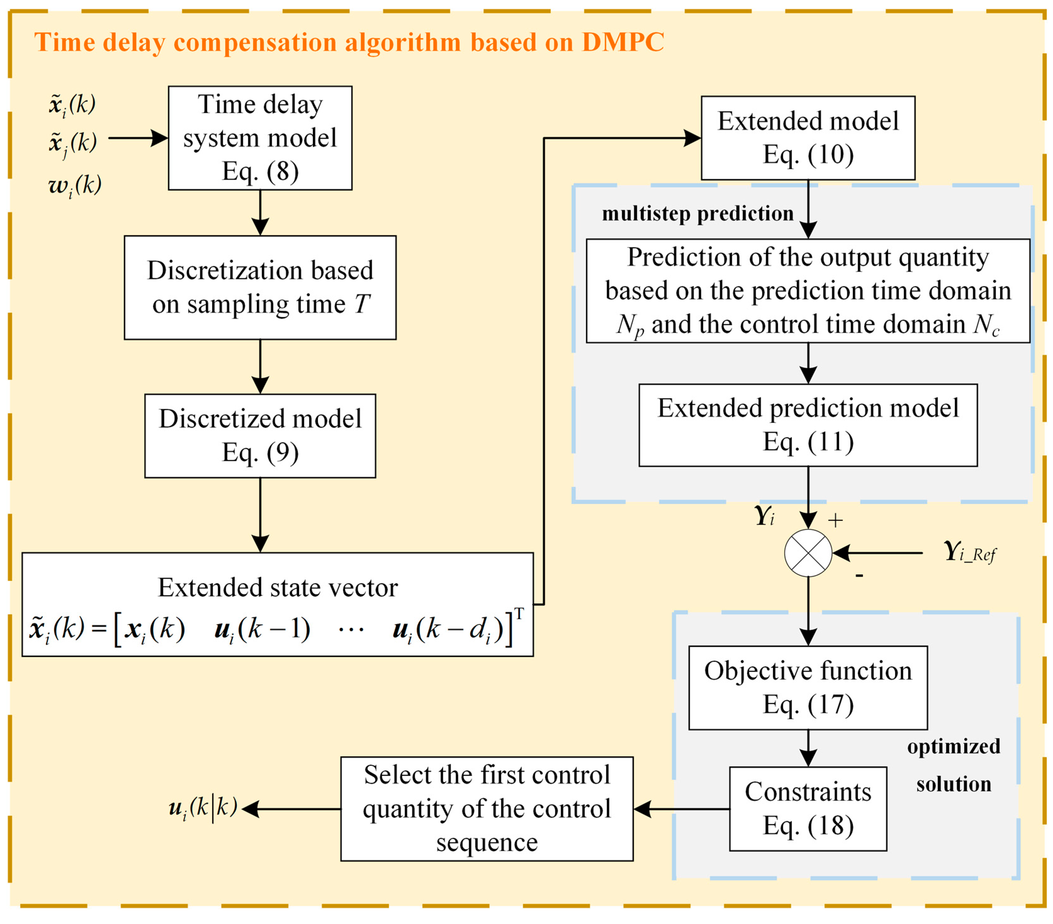
Section 4 proposes a TDC-DMPC framework, including a delay decoupling mechanism and a distributed optimization algorithm. Simulation results and conclusions are given in
Section 5 and
Section 6, respectively.
2. Distributed FR Architecture and Delay Analysis
2.1. Distributed FR Architecture
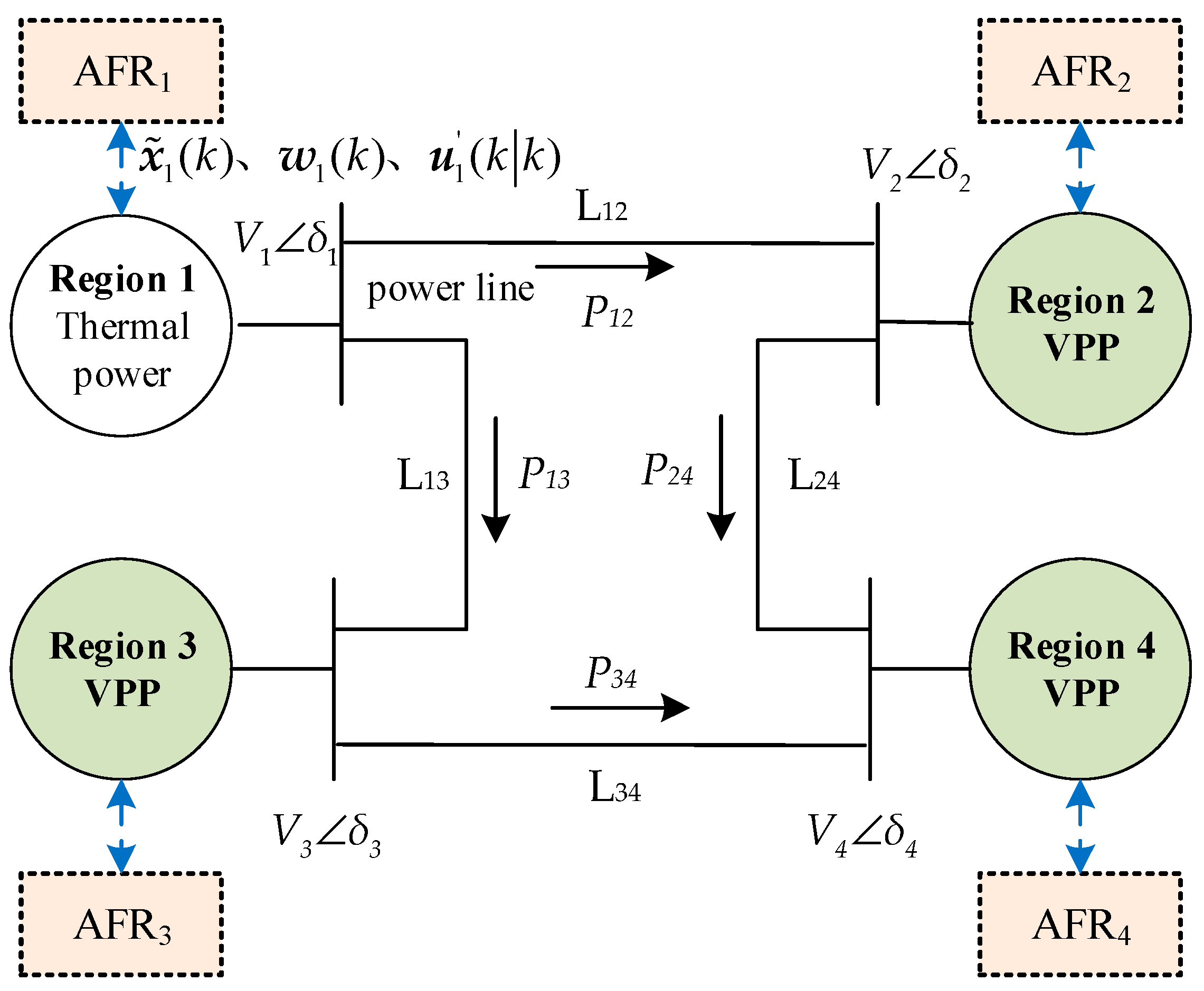
Flexible resources exhibit substantial potential for FR and are characterized by their widespread distribution across the grid, both in terms of quantity and geographic range. This distribution contrasts significantly with the centralized nature of conventional synchronous generators. A distributed FR architecture can effectively diminish the communication demands associated with VPP participation in FR through strategic grid partitioning. Furthermore, the inter-zone exchange of system information can mitigate overshoot and oscillation issues that may arise during independent frequency regulation efforts within zones, making it particularly well-suited for scenarios where VPPs engage in FR.
As illustrated in
Figure 1, the distributed FR architecture of the interconnected grid showcases a distinct operational paradigm compared to traditional ‘thermal power unit FR areas’. In areas lacking conventional synchronous generator capacity, the utilization of VPPs for frequency regulation is essential, as indicated by the ‘VPP FR region’ label in the figure. Each area’s control center is tasked with the unified management of FR resources, guided by information on grid frequency and the power dynamics of inter-area connections. Additionally, these control centers engage in collaboration with their counterparts in adjacent grid divisions to prevent excessive fluctuations in frequency dynamics throughout the FR process. This collaborative approach enhances the stability and reliability of frequency regulation efforts within the interconnected grid.
The flexible resources participating in frequency regulation within the VPP frequency regulation area encompass a diverse array of equipment, including electric vehicles, air conditioners, energy storage systems and other distributed resources. These resources are considerable in number and widely dispersed, necessitating their aggregation at a hierarchical level to establish a regulation and control capability that is comparable to that of traditional frequency regulation power plants. This aggregated capacity is then integrated with the FR control center, allowing it to contribute to the regulation of the interconnected grid’s frequency.
When the grid frequency deviates beyond a predetermined threshold, the control center of each region grid dispatches FR control instructions to both synchronous generator power and VPPs. Specifically for the VPP FR area, the VPP is responsible for transmitting control signals to the flexible resources under its jurisdiction. This enables the VPP to coordinate the response of the flexible resource clusters, ensuring that their aggregated power output aligns with the target power requirements dictated by the grid’s frequency regulation needs. Through this process, the VPP effectively harnesses the capabilities of its aggregated flexible resources, enhancing the overall stability and responsiveness of the interconnected grid in the face of frequency fluctuations.
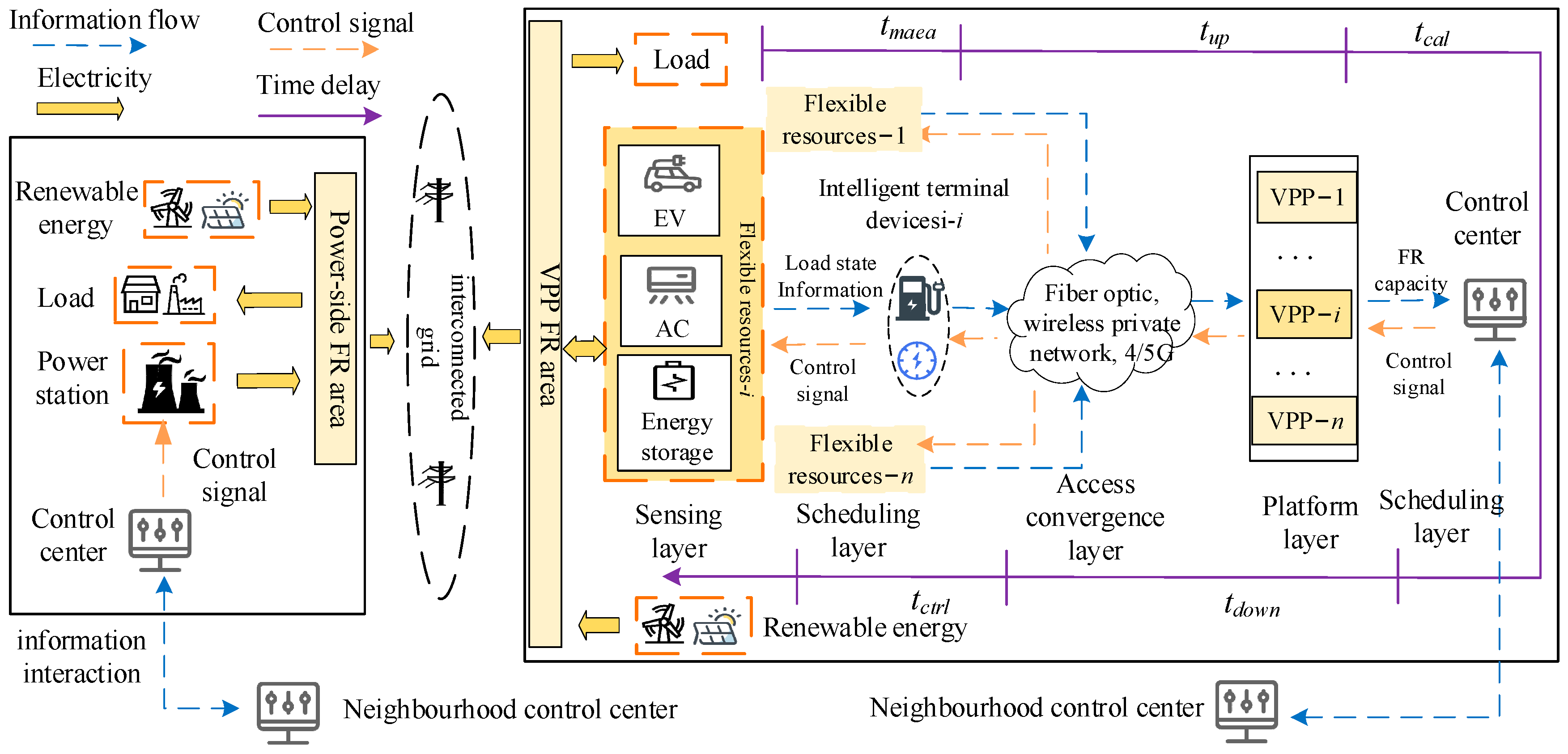
The architecture of the VPP FR system is organized into four distinct layers: the perception layer, access convergence layer, platform layer, and scheduling layer. This structured approach facilitates precise perception and real-time control of power grid operations.
Perception Layer: In this initial layer, load-side flexible resources utilize intelligent terminals to collect data on the operation of flexible loads and energy storage equipment, enabling effective power control and information gathering.
Access Convergence Layer: This layer serves as a critical link between the intelligent terminals located in the perception layer and the VPP situated in the platform layer. It employs various communication modes and connection topologies to ensure seamless integration and effective data transfer.
Platform Layer: Within this layer, the VPP plays a vital role in participating in the frequency regulation of the regional grid by aggregating a substantial number of flexible resources. The VPP operates under the unified control of the scheduling layer’s control center, ensuring coordinated management of these diverse assets.
Scheduling Layer: This uppermost layer oversees the coordination and scheduling of the VPP’s activities, aligning the collective output of flexible resources with the frequency regulation needs of the regional grid.
Given the multi-layered design of the VPP FR system, along with the various communication mediums and network architectures involved, it is essential to pay careful attention to potential communication delays. The complexity of this architecture can introduce delays in data transmission and response times, which could adversely affect the effectiveness of frequency regulation efforts. Therefore, it is imperative to develop strategies that mitigate communication delays and enhance the responsiveness of the VPP, ensuring optimal performance and stability within the power grid.
2.2. Time Delay Analysis with VPP Participating in FR
In
Figure 1, VPP participating in the FR may require relaying information with the help of various communication media such as optical fiber, wireless private network, public network, etc. In order to meet the demand for FR service, the cumulative delay of the channel should be controlled within the order of seconds [
26]. The information interaction between regional grid control centers, the control center of the thermal power unit FR area, and the synchronous generator power supply are all communicated point-to-point through the private network, and the fiber-optic channel’s delay is generally less than 20 ms [
27], which has a relatively small impact on FR control and can be ignored. Therefore, in this paper, we mainly consider the time delay that exists when a large amount of flexible resource aggregation in the sub-area participates in FR as a VPP, and the delay of its participation in the FR process contains five parts:
- (1)
tmeas: This represents the latency associated with the intelligent terminal’s collection and encapsulation of operational data from flexible resources. The duration of this process is closely linked to the efficiency of the terminal’s processing algorithms and generally falls within the milliseconds range.
- (2)
tup: This is the cumulative delay involved in the intelligent terminal uploading data to the control center incrementally. The duration of this delay is influenced by several factors, including the size of the transmitted data volume, the choice of transmission medium, network bandwidth, communication architecture, and the specifications of the network equipment. In scenarios where the data volume is substantial and network congestion occurs, this delay can extend to several seconds.
- (3)
tcal: Within this timeframe, the control center collects data from various sources and performs optimal calculations for control commands. This operation can typically be executed within 10 ms [
28].
- (4)
tdown: This delay constitutes the total time required for control commands to travel from the control center back to the intelligent terminal. Similar to tup., this delay is influenced by the same factors.
- (5)
tctrl: This is the time delay associated with the intelligent terminal’s response to the control commands. The duration of tctrl is primarily dependent on the hardware performance of the intelligent terminal, and it usually falls within the milliseconds range.
The cumulative delay resulting from these five components constitutes the total delay τ within the entire closed-loop control system. With the advancements in existing communication technologies, it is feasible to keep this total delay within the range of seconds, thereby facilitating efficient and effective frequency regulation through VPPs.
5. Simulation Results and Discussion
In this section, we conduct several simulations to demonstrate the effectiveness of the proposed control method and highlight the superiority of the delay compensation strategy in enhancing system stability. First, we investigate the role of VPP in maintaining frequency stability within interconnected power systems. Next, we compare various control strategies to illustrate their performance in frequency control. Following this, we analyze and compare the frequency control performance of three DMPCs under the influence of time delays. Finally, we examine the factors that affect the performance of the proposed TDC-DMPC in frequency regulation. Through these simulations, we aim to provide a comprehensive understanding of the proposed control approach’s effectiveness and its practical implications for power system management.
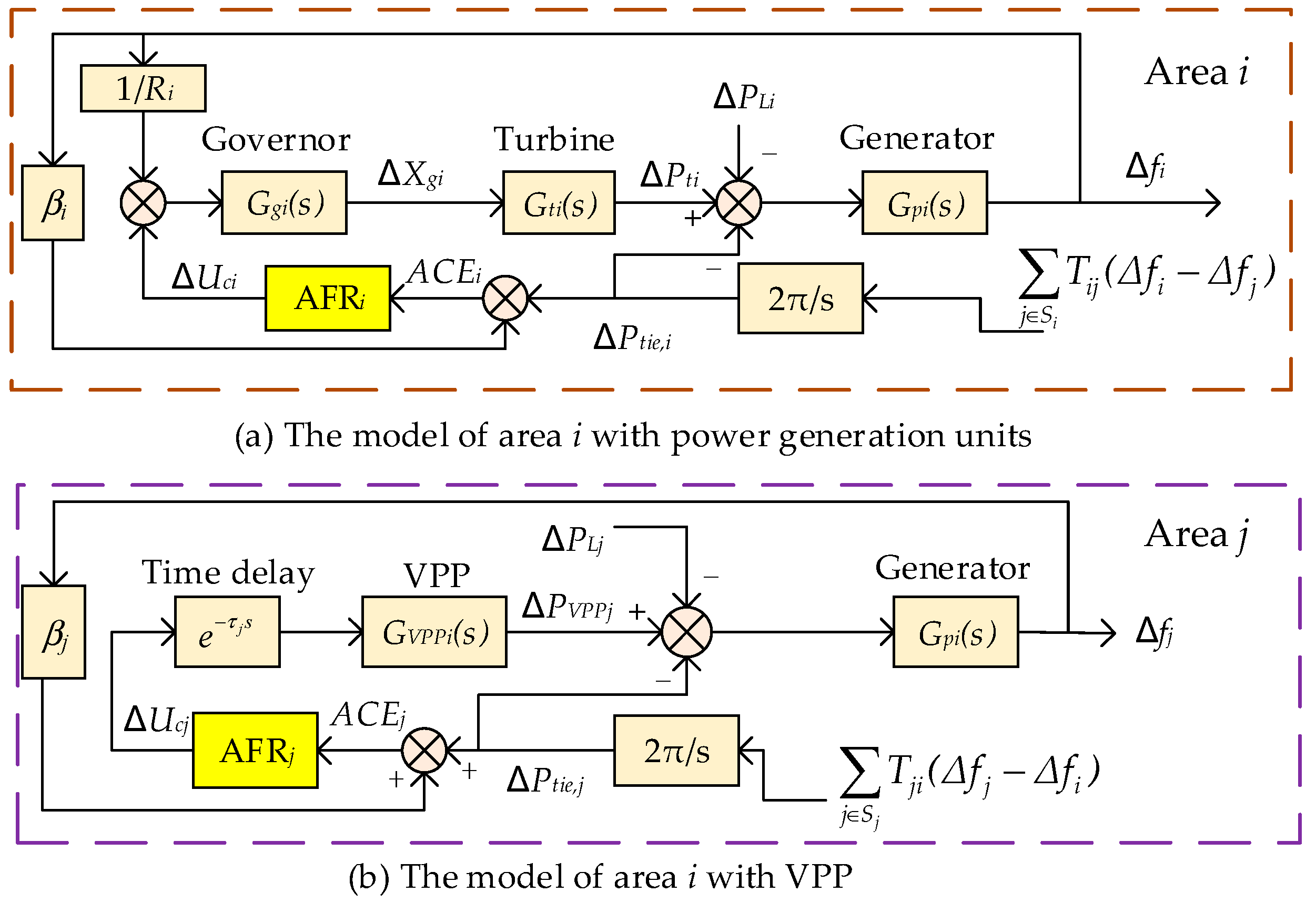
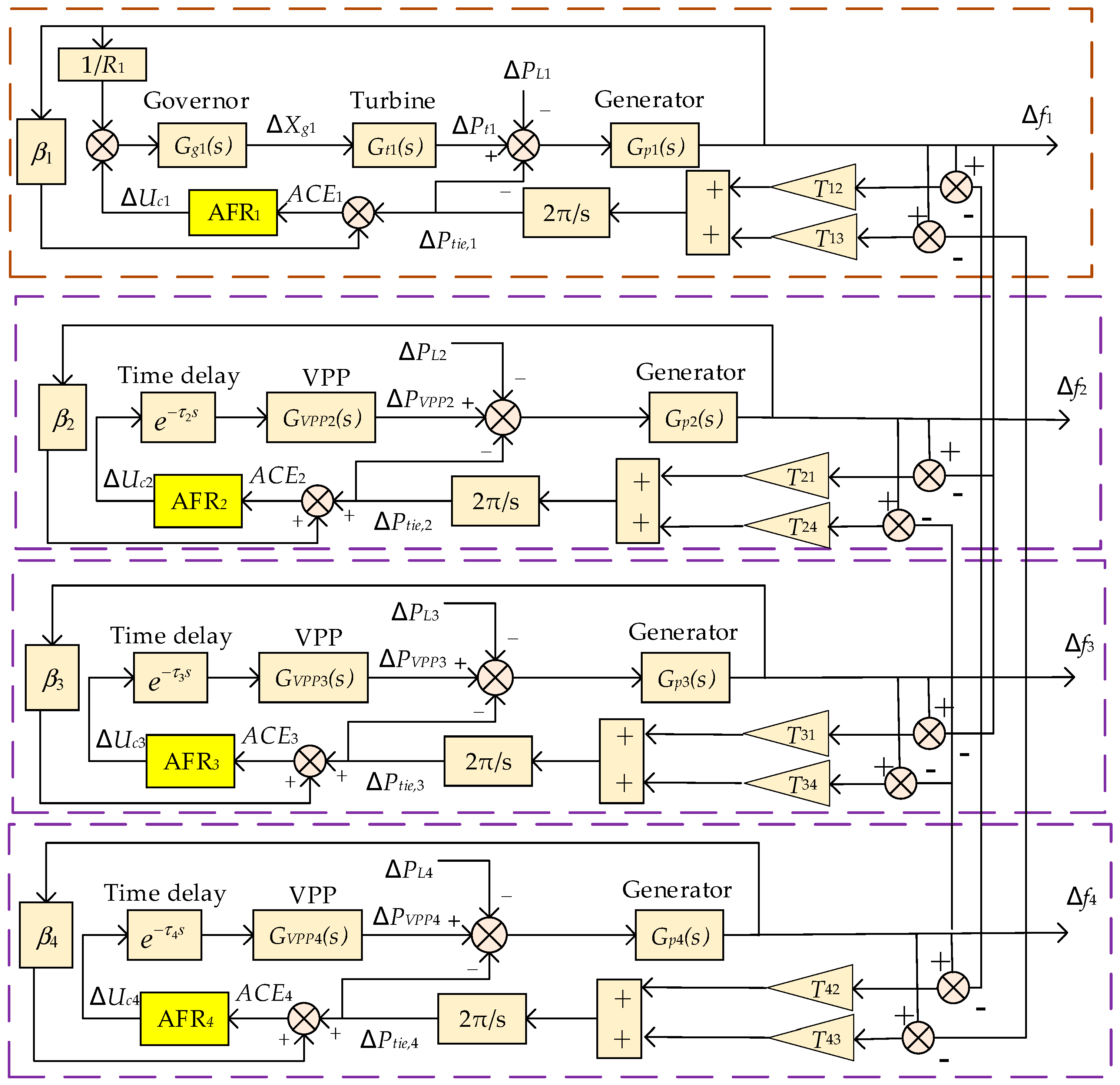
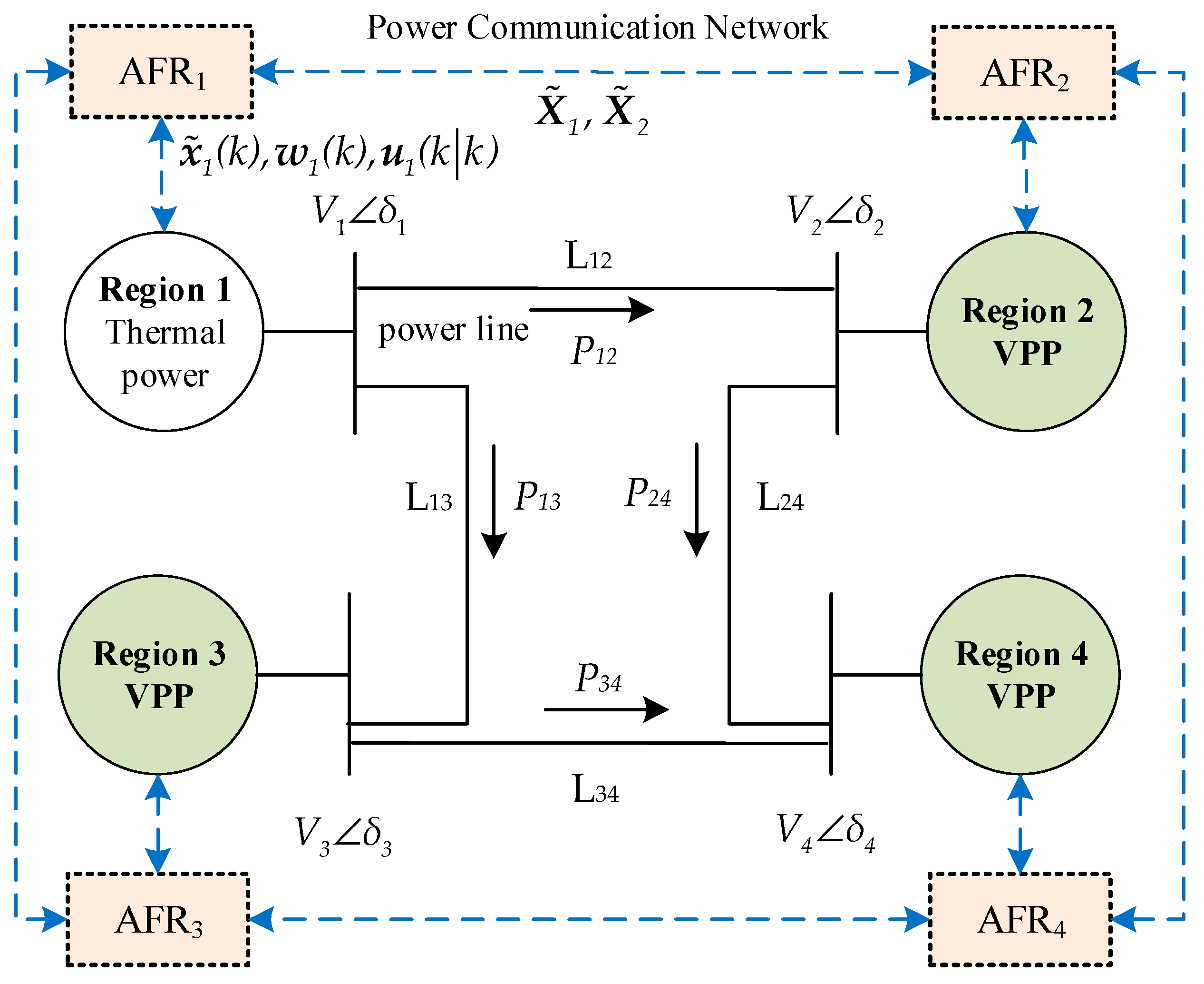
Based on the Matlab2020a platform, a four-area interconnected power system model is constructed as shown in
Figure 4, and the specific model structure is shown in
Figure 5. In the figure, area 1 utilizes thermal power for FR, the other three areas utilize VPP for FR. There exist tie lines and dedicated power communication networks between neighboring areas for power transmission and information interaction. The parameters of the power–frequency model of the zonal system are detailed in
Table 1.
Set the rated frequency of the power system at 50 Hz, with a power reference value of 3000 MW and a voltage reference value of 500 kV. Assume that the busbar voltage
Vi = 500 kV,
i = 1, ..., 4. The synchronization factor for interregional tie lines can be calculated from Equations (4) to (6); the calculation results are shown in
Table 2.
Note that the time delay τ is closely related to the prediction horizon. In order to achieve second-level prediction and delay control, set Np = Nc = 100 in this paper and the sampling period T to 0.01 s. The matrices R and Q are set as diag(1, ..., 1) and diag(10,000, ..., 10,000), respectively.
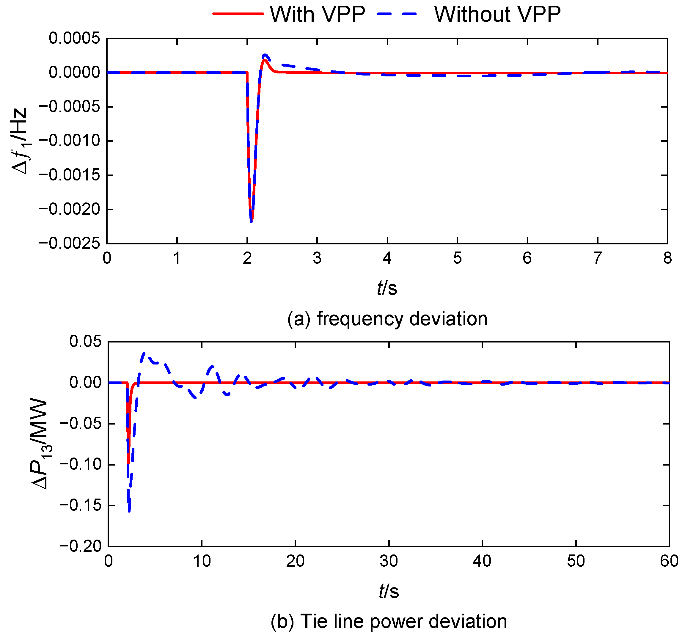
5.1. Response of the System Under VPP Participation in FR
This section compares and analyzes the system frequency modulation effect before and after VPP participation in AFR. The response delay of VPP (
τ = 0 s) is ignored for the time being, and the DMPC controller is used in all regions. The comparison curves of the amount of change in system frequency and tie line power before and after the VPP introduction are shown in
Figure 6 and
Figure 7.
Upon encountering a step perturbation with an amplitude of 0.01 p.u. in area 1, where the thermal power unit is participating in the AFR, as shown in
Figure 6, the system frequency and tie line power fluctuations are quickly suppressed, and the amount of overshooting is small after the VPP participates in the AFR.
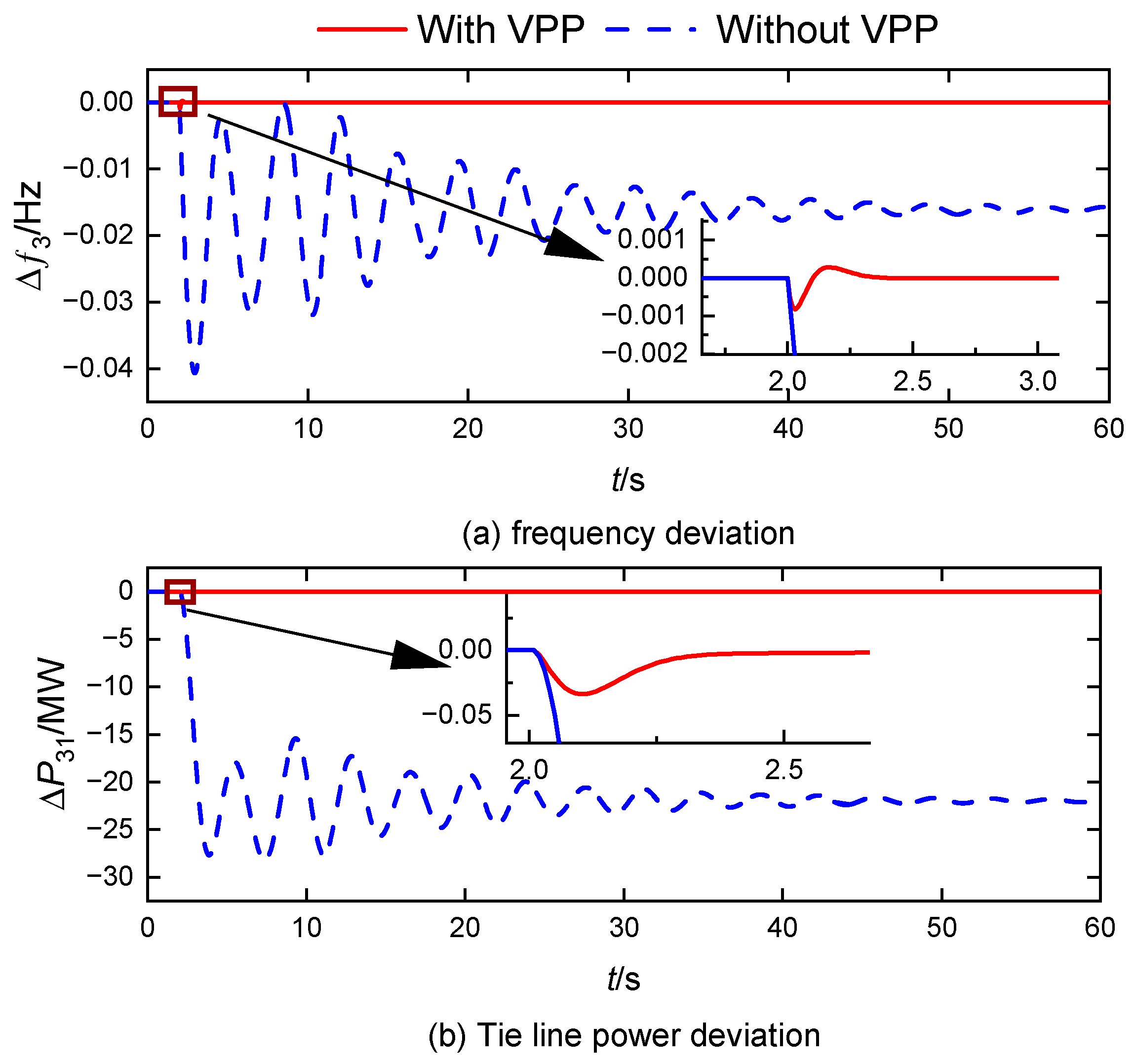
In the case of a step disturbance of the same amplitude occurring in area 3, where VPP is actively participating in the AFR, as shown in
Figure 6, the fluctuations in both system frequency and tie line power are again quickly dampened post-VPP participation. Additionally, this participation ensures that both the grid frequency deviation and the inter-area tie line power are restored to zero. In contrast, if the VPP does not engage in AFR—relying solely on the thermal power units in area 1—the ACE control mode necessitates that load power fluctuations in Area 3 are compensated by increments in the inter-area tie line power. This can ultimately hinder the system’s ability to achieve a zero differential regulation of the frequency.
In summary, the VPP’s flexible resources, due to their regional distribution characteristics, are capable of assuming the role of AFR in the absence of synchronous machine power supply within an area. This capability enhances the stability of the power system frequency under various disturbances and effectively mitigates large fluctuations in both frequency and tie line power.
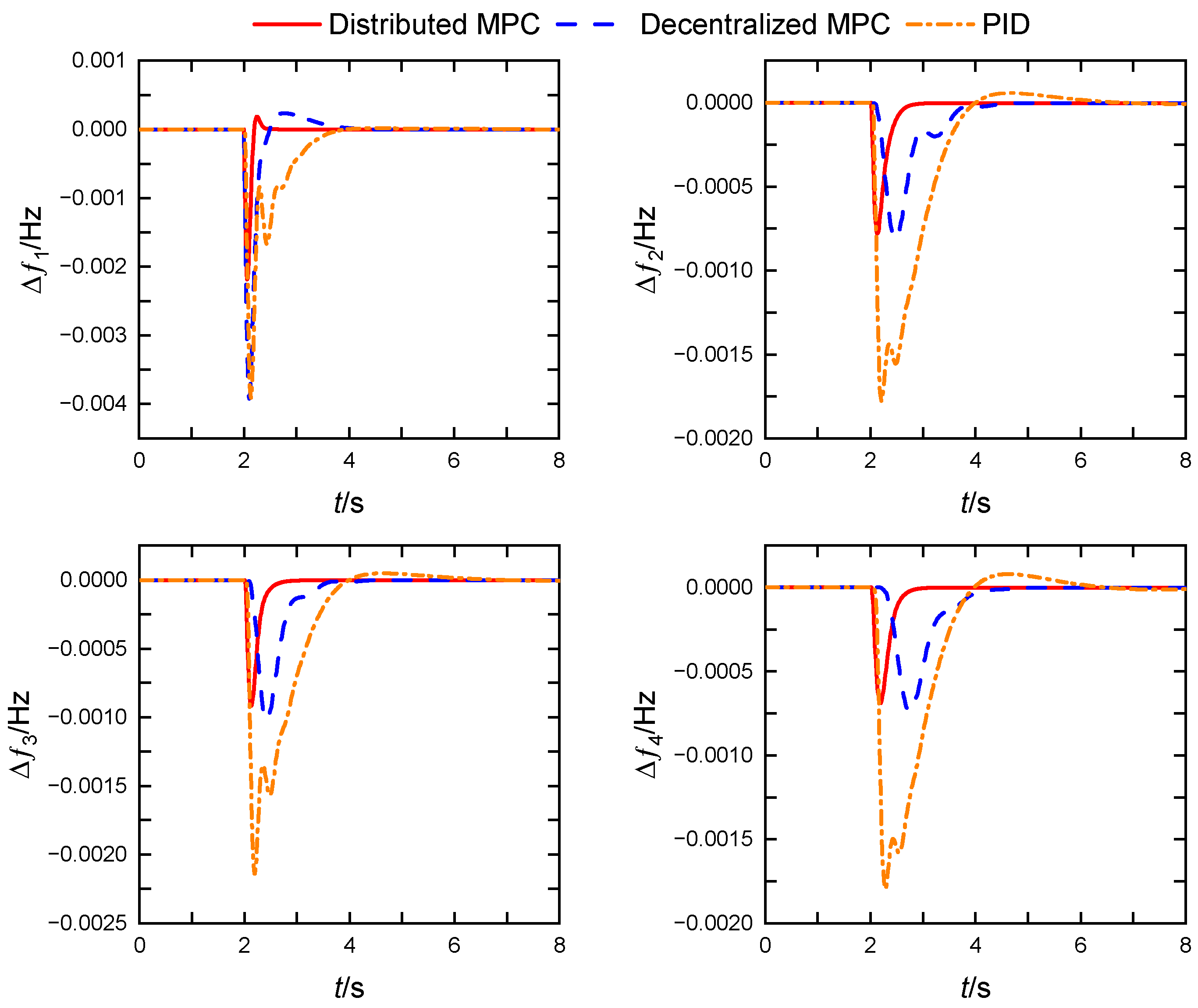
5.2. Comparison of Different FR Control Strategies
In this scenario, we discuss the frequency response performance of distributed MPC, decentralized MPC, and PID. It is assumed that the FR resources of all four partitions participate in the AFR time while ignoring the communication delay of the VPP response (
τ = 0). When a step disturbance of 0.01 p.u. occurs in area 1, the results shown in
Figure 8 and summarized in
Table 3 indicate that traditional PID control, constrained by fixed parameters, performs significantly worse than both decentralized MPC and distributed MPC in terms of FR effects. The decentralized MPC neglects the coupling between adjacent subsystems during its modeling, leading to greater overshooting and longer regulation times compared to the distributed MPC.
In contrast, the distributed MPC effectively incorporates the coupling relationships between partitioned systems in its design, enabling it to make optimal control decisions using both local and neighborhood information. As a result, its frequency regulation performance is markedly superior to that of both decentralized MPC and traditional PID controllers.
Note that the decentralized control structure is shown in
Figure A1 in
Appendix B. There is no communication link between the AFRs of each grid partition, and the partitioned AFRs make decisions and enact FR control based on the state information of the region. When designing the decentralized MPC, it is necessary to set
Aij in the power–frequency response model of the partitioned grid shown in Equation (8) as a zero matrix. The subsequent derivation process of the optimization design is the same as that of the DMPC.
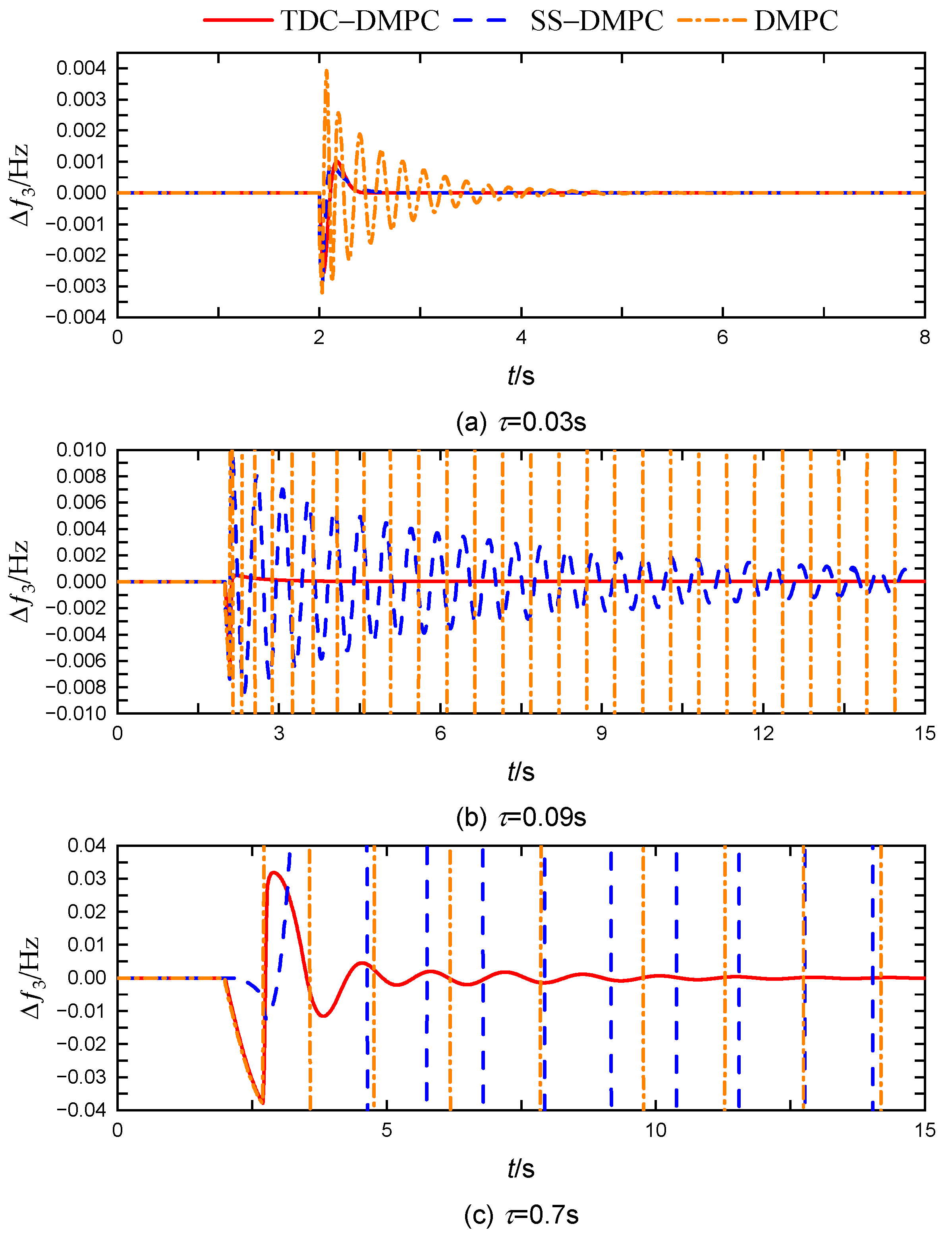
5.3. Comparison of Different DMPC Control Strategies Under Time Delay
This scenario further evaluates the FR performance of the TDC-DMPC developed in this paper, specifically under VPP delay response during the AFR. For comparison, the widely used sequence-selective DMPC (SS-DMPC) designed for time delays is also examined.
When a step perturbation with an amplitude of 0.01 p.u. occurs in the load in area 3, the frequency regulation effects of the three DMPCs under varying delays
τ are presented in
Figure 9, with quantitative analysis results detailed in
Table 4.
As illustrated in
Figure 9 and
Table 4, the traditional DMPC can maintain stability with
τ = 0.03 s; however, the system frequency fluctuations are significantly more pronounced than those experienced with the other two DMPCs, indicating its limited capacity to handle time delays. The SS-DMPC can tolerate a VPP delay of approximately 0.1 s, but closer to this threshold, the system frequency fluctuations become very severe, resulting in a regulation time exceeding 13 s. In contrast, the TDC-DMPC proposed in this work effectively maintains a robust frequency regulation performance even with a VPP response delay of up to 0.7 s.
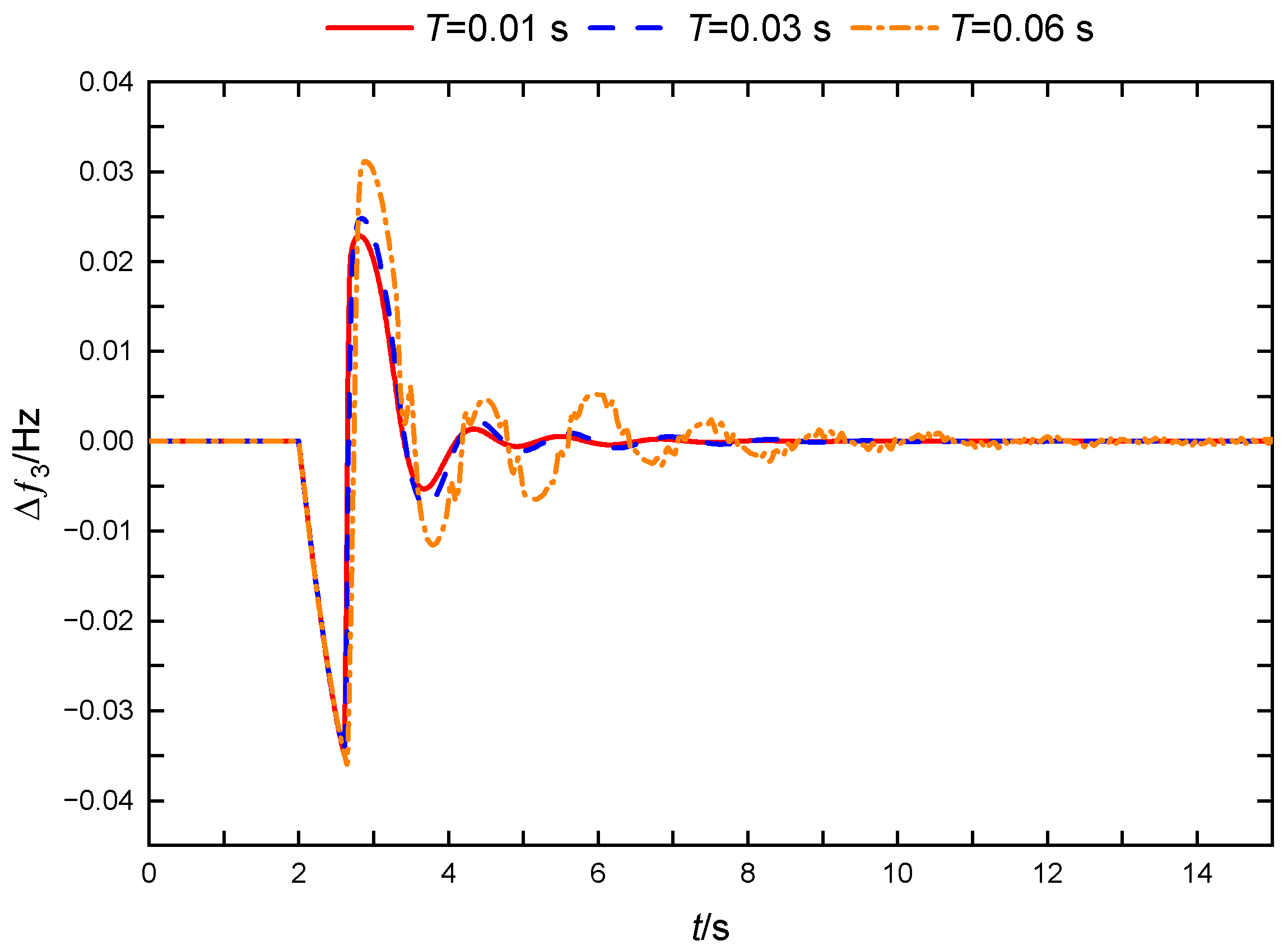
5.4. Analysis of Influencing Factors on the Effectiveness of TDC-DMPC in FR
In this section, we analyze a delay response AFR scenario with VPP participation to evaluate how sampling time, partition coupling, and parameter ingestion affect the effectiveness of the TDC-DMPC. Simulations were performed on the MATLAB 2020a platform using a 12th-generation Intel Core i7 2.30 GHz processor and 16 GB of RAM.
When a step disturbance of 0.01 p.u. occurs in the load of area 3 with
τ = 0.6 s, the control effects of TDC-DMPC under varying sampling times are illustrated in
Figure 10. At a sampling time
T = 0.01 s, the system demonstrates optimal frequency dynamic response performance. However, as the sampling time increases, the model prediction accuracy declines, leading to greater frequency overshoot, longer regulation times, and progressively poorer control effectiveness of the TDC-DMPC.
Additionally, the sampling time is intrinsically linked to the computational burden, as shown in
Table 5. A larger sampling time reduces the number of delay steps that must be accounted for, resulting in a smaller matrix dimension for the time-delay system’s generalized prediction model. This decrease reduces the frequency of rolling optimizations needed to solve for the optimal control quantity, thereby lowering computational time and overall burden. It is noteworthy that under the experimental conditions described, when
T = 0.01 s, the single-step solution time for the controller is 0.044 s, which exceeds the sampling period. Consequently, the computational delay introduces additional impacts on control performance. This issue may be addressed by utilizing a more powerful processor or increasing the sampling time appropriately.
The strategic determination of sampling intervals becomes critical for resolving the inherent trade-off between dynamic frequency regulation fidelity and computational resource constraints in power system control. This parameter optimization challenge holds significant engineering relevance, particularly when addressing real-time operational requirements under limited processing capabilities.
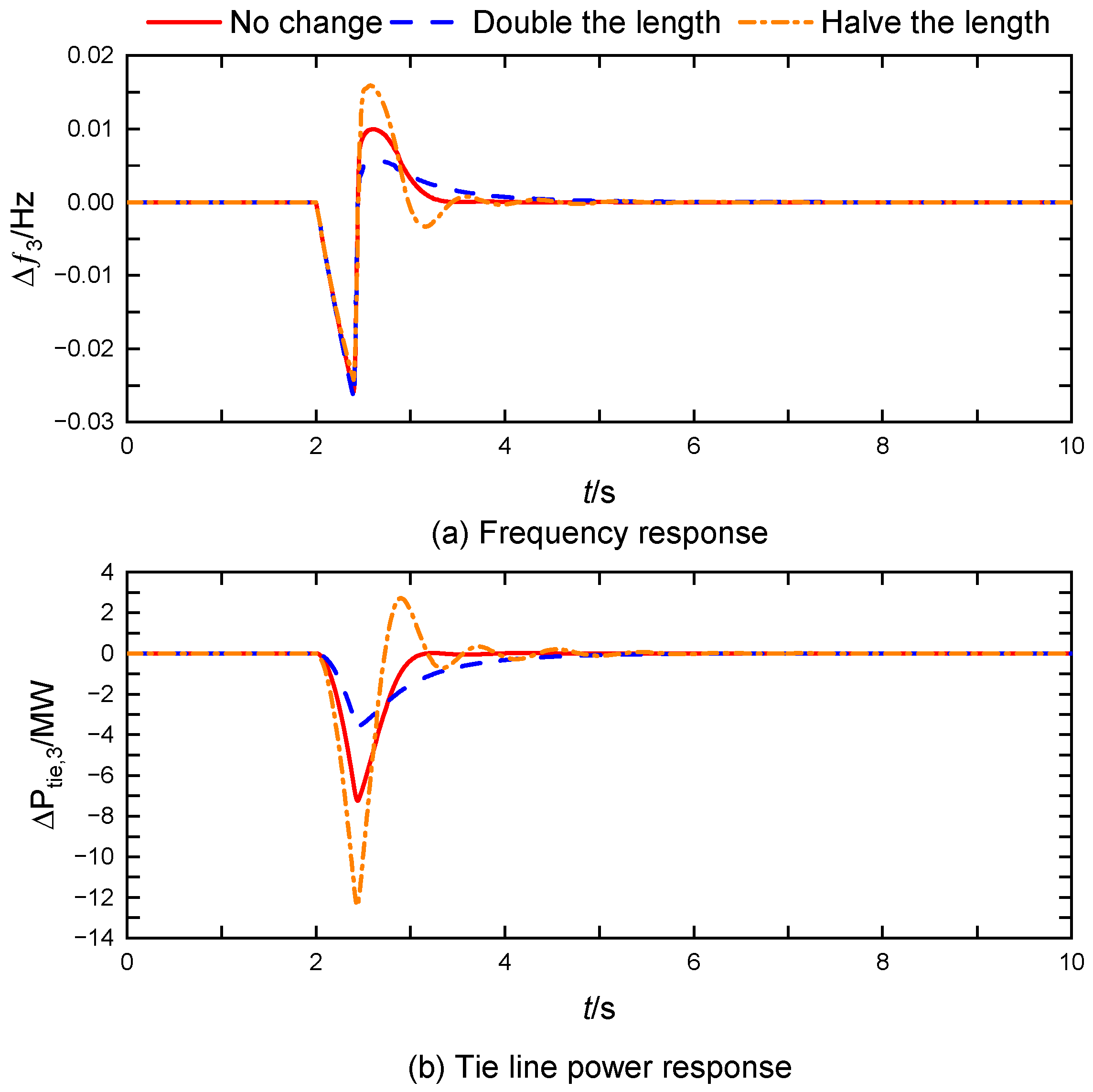
As the inter-district tie line length decreases, the coupling between the interconnected grids increases, which complicates the frequency regulation and control efforts. The TDC-DMPC control effect under different tie line lengths is shown in
Figure 11 and the corresponding synchronization coefficients are shown in
Table 6. As can be seen from the graph, the longer the distance between zones, the better the control effect of TDC-DMPC. Under a certain transmission power
Pij of the tie line, the longer the length of the tie line L
ij, the larger the power angle difference between the regions Δ
δij. According to Equation (6), the synchronization coefficient
Tij becomes smaller as Δ
δij becomes smaller, which leads to weaker coupling between areas. The decrease in coupling in the interconnection region directly leads to a smaller power variation of the tie line
Pij in disturbed area 3, which reduces the corresponding overshoot. This shows that the TDC-DMPC proposed in this paper can maintain a good control effect under different tie line lengths.
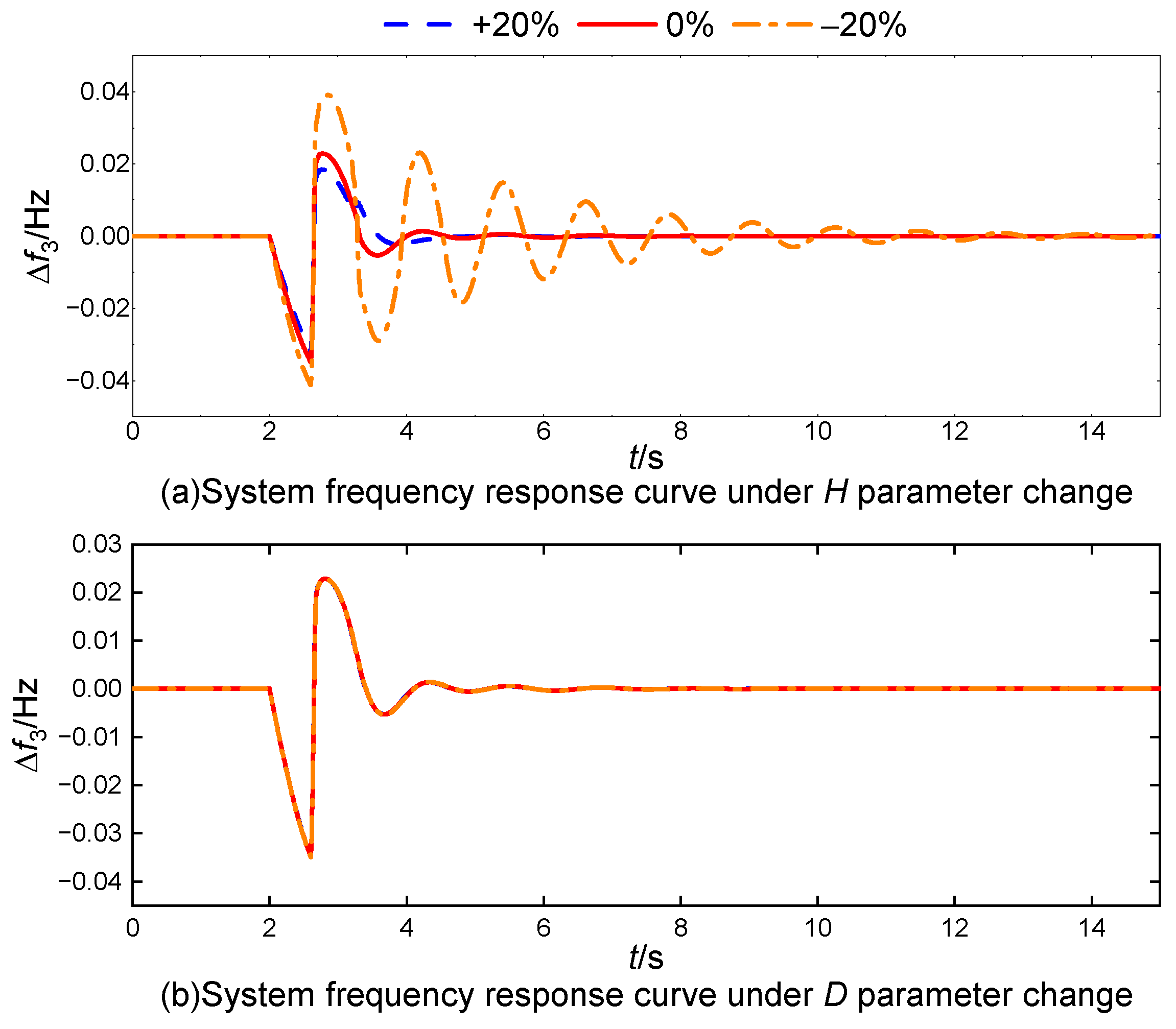
To evaluate the impact of possible deviations in system model parameters on the transient frequency regulation performance, we specifically analyze two key parameters: the inertia coefficient
H and the damping coefficient
D. The results of this analysis are depicted in
Figure 12.
From
Figure 12, it is evident that a 20% reduction in the inertia coefficient
H leads to an increase in system frequency deviation and an extension of the oscillation duration. Despite these changes, the system succeeds in stabilizing after approximately 14 s. In contrast, variations in the damping coefficient
D by ±20% have negligible effects on the frequency response. The behavior of other model parameters shows similar resilience.
These findings suggest that the TDC-DMPC exhibits a robust performance against parameter variations in the model, emphasizing its effectiveness in maintaining stability and control even in the presence of deviations. This robustness is critical for practical applications where exact parameter values may not be attainable due to uncertainties or dynamic changes in the system.
6. Conclusions
In this paper, for the time delay problem when VPP participates in grid FR, we construct a mathematical model that integrates the dynamic response of VPP with the characteristics of traditional generating units, and we propose the TDC-DMPC strategy. The strategy significantly improves the frequency dynamic response capability of the multi-area grid through optimization of the distributed architecture and through the history state reconstruction mechanism, while guaranteeing the system time delay robustness. MATLAB-based simulation verification shows that TDC-DMPC can effectively suppress the frequency fluctuation caused by VPP delay, enhance the transient stability of the grid, and provide a new idea for flexible frequency regulation under an environment with a high percentage of new energy access. The study shows that incorporating VPP into the regional grid cooperative FR system not only reduces the dependence on traditional thermal power FR but also improves the overall system flexibility through the resource aggregation effect, and this direction will become an important path for the transformation of the new power system.
Despite the encouraging results, MATLAB/Simulink simulation is currently the only working platform for this research. It is important to note that the research work in this paper was conducted with known model parameters and fixed latency. For real power systems, the FR model parameters may be difficult to obtain accurately due to the working environment; at the same time, the communication delay generally appears in the form of random values during network transmission. The TDC-DMPC proposed in this paper increases the computational burden due to the expansion of the coefficient dimensions, which is also a limitation of the method proposed in this paper.
Future research needs to complete hardware-in-the-loop (HIL) testing to verify its real-time performance and deal with practical problems such as communication delays and hardware constraints; at the same time, it should also be combined with online parameter identification techniques to further optimize the control adaptability under stochastic delay scenarios and facilitate the transition of the theoretical methodology to engineering applications (e.g., validation of the IEEE standard test model), so as to provide technical support for the construction of a sustainable energy system.


