Abstract
Background/Motivation: Viscous dissipation enhances temperature. Determination of its impact is needed to avoid degradation of products in industrial processes. Methodology: The inlet-filled thermal entrance region model addresses the Graetz–Brinkman problem of viscous dissipation in developing heat transfer in a tube subject to a constant heat flux at the wall, considering Newtonian, pseudoplastic, and dilatant fluids. The inlet-filled region concept is used to solve for developing heat transfer, with the thermal entrance region divided into a thermal boundary layer zone, called the thermal inlet region, ending at the point where the thermal boundary layer fills the whole tube cross section, followed by a thermally filled region where fully developed conditions are asymptotically reached. Key Results: The model is essentially analytical. The results include profiles of the dimensionless thermal boundary layer thickness, Nusselt number, dimensionless bulk, wall and centerline temperatures, and entrance region length for different values of the Brinkman number and power-law index, with validation against the derived fully developed solution and published results. Implications: New results are obtained for the case of nonzero viscous dissipation. Results can be obtained with minor computational tasks needed.
1. Introduction
Power-law fluids constitute a very large class of non-Newtonian fluids including polymer solutions and polymer melts. Large temperatures may lead to degradation of products in industrial processes. For highly viscous fluids, viscous dissipation enhances temperature and amplifies the problem [1]. Determination of the impact of viscous dissipation is needed in such cases. The Graetz–Nusselt problem [2] consists of developed laminar fluid flow and developing heat transfer in a tube subject to a constant wall temperature (isothermal case). Its extensions include the constant heat flux at the wall (isoflux) case. Reviews can be found in Mandapali [3], Khan and Ali [4], and the references therein.
Investigations of developing heat transfer treatments for Newtonian fluid flow include the works of Graetz and Nusselt (isothermal case) [2]. Siegel et al. [5] addressed the uniform flux case using a series expansion method. Salazar et al. [6] solved the isothermal and isoflux cases using a combination of separation of variables and the method of lines. Mandapati [3] included axial conduction and viscous dissipation in the investigation of the isoflux case. The numerical solution (successive accelerated replacement) provided shows small axial conduction effects for a Peclet number above one hundred. Ou and Cheng [7] included viscous dissipation and used separation of variables to solve the isoflux case.
Power-law fluids include Newtonian (n = 1), pseudoplastic (n < 1), and dilatant fluids (n > 1). Extensions of research investigations to the cases where n ≠ 1 include the work of Bird [8], addressing the isoflux case and providing asymptotic solutions near the inlet using the Leveque approximation, an asymptotic solution far from the inlet, in addition to the general solution, expressed theoretically as a function of Eigen values and functions. Lyche and Bird [9] provided a semi-analytical solution for the Graetz–Nusselt problem. Cotta and Özişik [10] provided a formal solution including viscous dissipation, considered as a function of the radial coordinate only, and expressed in terms of Eigen functions and Eigen values. The numerical solution provided in [10] applies to the case of negligible viscous dissipation and includes a comparison with the asymptotic solution in Bird [8]. Khellaf and Lauriat [11] addressed the isothermal case using separation of variables with spectral decomposition, while ValkÓ [12] and Manglik and Prusa [1] included viscous dissipation, using the Laplace transform Galerkin method in [12], and a finite-difference scheme in [1]. Barletta and Magyari [13] and Dehkordi and Memari [14] considered the case where the inlet stream to a tube section subject to uniform flux downstream, is the outlet stream leaving an adiabatic tube section upstream, sufficiently long for the flow to be hydrodynamically and thermally fully developed. A Laplace transform method is used to solve the Newtonian fluid problem in [13], and a finite difference scheme is adopted to solve the power-law fluid case in [14]. Khan and Ali [4] addressed the Graetz–Brinkman problem for isothermal and isoflux boundary conditions, assuming slip at the wall.
Simultaneously developing and heat transfer were addressed by Al-Ali and Selim [15] and Chebbi et al. [16], using the inlet-filled region concept to solve the Newtonian fluid case for the isoflux problem in [15] and the isothermal problem in [16] for different Prandtl numbers, while Hassan and Chebbi extended the isoflux analysis to power-law fluids [17]. Etemad [18] included viscous dissipation effects and solved the power-law fluid flow case using the isothermal and isoflux boundary conditions at the wall, Reynolds number = 500, Prandtl number = 10, and the Galerkin finite element method.
The inlet-filled region concept was introduced by Ishizawa [19], to investigate developing radial flow between parallel disks, and later used to analyze developing flow in circular pipes by Mohanty and Asthana [20]. The entrance region, according to this concept, consists of a combination of an upstream region, called the inlet region, where the hydrodynamic boundary layer thickness grows to reach its maximum value, followed by a filled region in which the flow keeps readjusting to asymptotically reach the fully developed velocity profile. The concept, initially introduced for developing fluid flow, was extended by Habib and Selim [15] to treat simultaneously developing heat transfer and Newtonian fluid flow in a circular tube. The successful investigation in [15] for the constant of uniform heat flux was extended by Chebbi et al. [16] to the isothermal case. The case of developing power-law fluid flow was successfully solved by Chebbi [21] using the inlet-filled region concept, with the analysis of simultaneously developing heat transfer successfully added to the model in [21] by Hassan and Chebbi [17] in the case where viscous dissipation effects can be neglected. In the case of highly viscous power-law fluids, viscous effects need to be included as this leads to higher temperatures.
In summary, the investigations addressing fully developed power-law profile and thermally developing heat transfer in an isothermal circular tube (Graetz-Nusselt problem) are considered in [1,9,11,12]. A formal solution is provided in [8] for the corresponding isoflux Graetz problem (uniform inlet temperature) assuming no viscous dissipation. The formal solution, including the viscous dissipation term, Eigen functions, and Eigen values provided in [10], is solved numerically in the case of small viscous dissipation [10]. Viscous dissipation is included in [4] assuming slippery walls. Refs. [13,14] address the isoflux Graetz problem case for a hydrodynamically and thermally developed inlet stream leaving a sufficiently long adiabatic tube. Simultaneously developing power-law fluid flow and heat transfer in circular tubes subject to uniform heat flux is addressed in [17], using the inlet-filled region concept with viscous dissipation effects assumed negligible, while viscous dissipation effects are included using the Galerkin finite element method in [18] with simulations done for Reynolds number = 500 and Prandtl number = 10 [18].
The present investigation addresses developing heat transfer of fully developed power-law fluid flow in a tube, for the case of uniform inlet temperature and uniform heating flux at the wall with viscous dissipation included (Graetz–Brinkman problem) using the inlet-filled region concept. Previous investigations, as summarized above, are different in terms of solution methodology and scope from the present one: the Graetz–Brinkman problem for uniform wall heat flux, uniform inlet temperature, and viscous dissipation included for developing heat transfer and fully developed power-law fluid flow. In particular, the work of Etemad [18], addressing simultaneously developing power-law flow and heat transfer, only provides results for Re = 500 and Pr = 10, as mentioned above.
In contrast to previous works, the present investigation uses a different and predominately analytical model, based on the inlet-filled region concept, and requiring minor computational work. The model provides extensive results including wall, bulk, and centerline temperature profiles, Nusselt number profiles, and dimensionless thermal entrance region lengths for zero and nonzero Brinkman numbers (viscous dissipation case) for the three cases: Newtonian, pseudoplastic, and dilatant fluid flows.
The model used is described first, followed by a presentation of the solution methodology, results and discussion, and conclusions, including recommendations for investigations involving viscous dissipation in nonisothermal flows based on the recent theoretical investigations in Baranovskii [22] and Baranovskii and Shishkina [23] in relation to solvability, uniqueness of solution, and stability.
2. Model
The extended Graetz problem considered consists of fully developed power-law fluid flow in a tube subject to a uniform heating flux at the wall, where developing heat transfer occurs. According to the inlet-filled region concept extended in [15] to developing heat transfer, the thermal entrance region consists of two zones: the thermal inlet region where transverse heat conduction effects are limited to the thermal boundary layer, followed by the thermally filled region where heat conduction is present in the whole tube cross section. The governing equations are developed for both regions.
2.1. Governing Equations
The fully developed laminar fluid flow profile is given by [2]:
where u and Uc denote the velocity at radial coordinate r and the centerline velocity, respectively, R is the inner tube radius, and q is defined as 1 + (1/n). Figure 1 depicts the problem considered with the system of coordinates used.
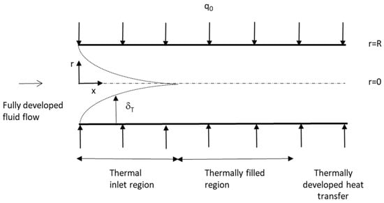
Figure 1.
Schematic of developing heat transfer in a circular tube for fully developed fluid flow (isoflux Graetz problem), showing the thermal inlet region and the thermally filled region together forming the thermal entrance region.
Considering viscous dissipation, the heat transfer equation is given by [2]:
The temperature profile is subject to the following boundary conditions:
where T0, Tc, and T represent the uniform inlet temperature, the centerline velocity, and the local temperature, respectively, x denotes the axial coordinate, q0 is the uniform heat flux at the wall, K, ρ, α, and k denote the power-law consistency index, density, thermal diffusivity, and thermal conductivity, respectively, and ΓT is the thermal shape factor [15].
2.2. Approximate Temperature Profile
A Von Kármán integral approach is selected, using the approximate temperature profile expression:
where
Using the boundary conditions in Section 2.1, along with the approximate polynomial temperature profile, Equation (7), and solving the linear system of equations obtained yields the expressions in Table 1.

Table 1.
Coefficients of the approximate temperature profile ( in the thermal inlet region and in the thermally filled region).
Where
2.3. Integral Energy Equation
Integrating the heat equation, Equation (2), yields
In dimensionless form, the fully developed velocity profile [2] is expressed as
with , defined as , is set to 1 in the thermally filled region.
Substituting in the dimensionless form of Equation (10) gives
where the Brinkman number is defined as and
2.4. Fully Developed Temperature Profile
Substituting for the fully developed velocity profile [2],
in Equation (2) gives in dimensionless form
Extending the approach in [2,8,17], we seek a solution for the fully developed profile of the form
Substituting into Equation (15) gives an ordinary differential equation,
Integrating two times while imposing a finite value of ψ at ε = 0 yields
Using Equation (4) yields
Instead of using B.C.1, we use an integral form of the energy Equation as in [2]. Multiplying all terms in Equation (15) by ε, and integrating with respect to ε between 0 and 1 and with respect to χ from 0 to χ, yields after identification of the χ terms [17]
Integrating the above expression provides
2.5. Nusselt Number
The Nusselt number is defined as
with the bulk temperature provided by
In a dimensionless form, we have
with Tc = T0 in the thermal inlet region and set to 1 in the thermally filled region.
3. Solution Methodology
3.1. Asymptotic Solution
Close to the origin, is small, and the following approximations of Equations (13) and (11) can be used:
Using an approximate quartic temperature profile near the origin,
and integrating Equation (26), while setting the thermal boundary layer thickness to zero at the origin, yields
3.2. Fully Developed Nusselt Number and Thermal Shape Factor
Applying Equation (24) in this case gives
Using Equation (18) shows that the χ terms cancel out, with Equation (29) reducing to
The fully developed thermal shape factor is obtained from the definition Equation (6), and the fully developed temperature profile (Section 2.4):
3.3. Numerical Solution
(i) Thermal inlet region
Using the chain rule in Equation (11) yields the following:
where
Substituting for the dimensionless velocity profile in Equation (32) gives
Substituting for the approximate temperature profile, Equation (27), and integrating yields
Integrating by parts yields the following recurrence relation:
starting at k = j, using
(ii) Thermally filled region
Using the chain rule in Equation (11) yields the following:
where
The expressions for g, Equations (35)–(37), can be used with set to 1 in the thermally filled region.
4. Results and Discussion
The thermal entrance region consists of two zones. Integrating Equation (32) provides the dimensionless thermal boundary layer thickness profile. Equation (28) is used to initiate integration to avoid the well-known singularity with infinite slope at the origin. The thermally filled region solution starts at the location where reaches one. Solving for the thermal shape factor is performed using Equation (38).
At the wall, we have the following:
with Tc = T0 in the thermal inlet region and set to 1 in the thermally filled region.
Using the energy equation at the centerline along with L’Hôpital’s rule gives
and in dimensionless form,
In the thermal inlet region, is zero and the centerline temperature, Tc, remains equal to the inlet temperature T0. Integrating Equation (42) in the thermally filled region provides = θc.
The corresponding fully developed expression is
The following expressions can be used to determine profiles for Nu, θw, and θb. Using Equation (28) gives the following expression for the Nusselt number:
Using Equations (7) and (8) yields
Furthermore, using Equation (24) provides
Integration of Equation (32) in the thermal inlet region, and Equations (38) and (42) in the thermally filled region, were performed using the fourth order Runge–Kutta adaptive step size FORTRAN subprograms, RKQC and RK4, in [24].
The profiles for the dimensionless wall temperature, θw (Figure 2), bulk temperature, θb (Figure 3), and centerline temperature, θc (Figure 4), show increasing values at higher values of the dimensionless axial distance ξ and Brinkman number, Br. The fully developed expression for the centerline temperature gradient, Equation (44), is found identical to the asymptotic limiting expression obtained from Equations (31) and (42). The results are also found to be in good agreement with the ones for θw and θb in Ou and Cheng [7] (Figure 2 and Figure 3). Close values for different values of n (1, 2, and 0.5) are found at Br = 0, with larger values at lower values of n at Br = 2 and 4 for θw, θb, and θc.
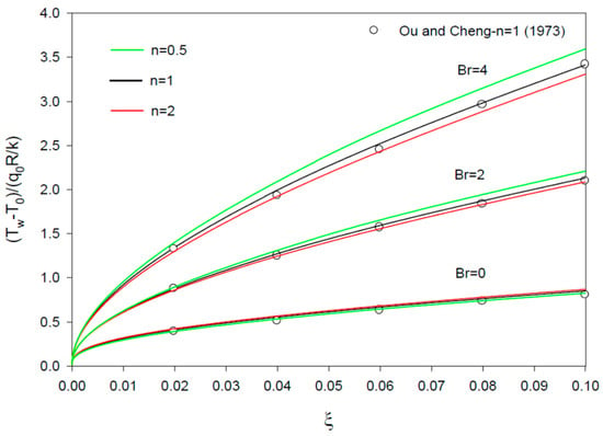
Figure 2.
Profiles of θw vs. ξ = x/(R Re Pr) for n = 1 (Newtonian fluid), 2, and 0.5, and Br = 0, 2, and 4. The results for n=1 are compared with those of Ou and Cheng [7].
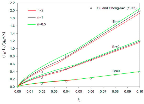
Figure 3.
Profiles of θb vs ξ = x/(R Re Pr) for n = 1 (Newtonian fluid), 2, and 0.5, and Br = 0, 2, and 4. The results for n=1 are compared with those of Ou and Cheng [7].
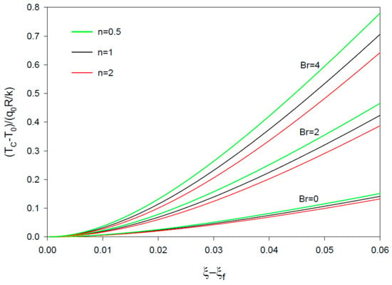
Figure 4.
Profiles of θc vs. ξ − ξf = (x − xf)/(R Re Pr) in the filled region for n = 1 (Newtonian fluid), 2, and 0.5, and Br = 0, 2, and 4 (θc = 0 in the inlet region; Tc = T0 at ξ < ξf).
The profiles for the Nusselt number show decreasing values at larger ξ, larger n, and smaller Br values (Figure 5, Figure 6 and Figure 7). Good agreement is noticed with Ou and Cheng’s results (n = 1 and Br = 0, 2, and 8) [7] (Figure 5), and the finite difference results of McKillop [25] for simultaneously developing flow and heat transfer at a high Prandtl number and Br = 0 (Figure 5 and Figure 7). Small deviations are found for the asymptotic values of the Nusselt number in comparison with the fully developed values for n different from one (Section 3.2), with zero deviations found for the Newtonian fluid flow case (n = 1).
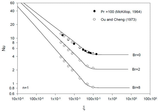
Figure 5.
Profiles of Nu vs. ξ = x/(R Re Pr) for Br = 0, 2, and 8 (n = 1, Newtonian fluid). The results are compared with those of McKillop [25] and Ou and Cheng [7].
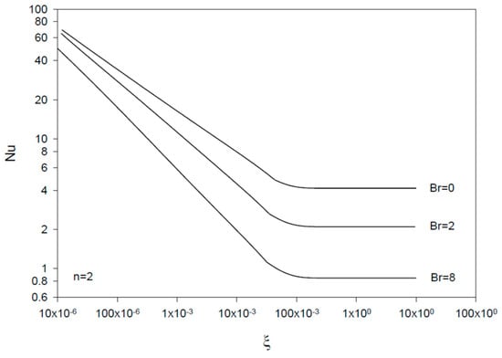
Figure 6.
Profiles of Nu vs. ξ = x/(R Re Pr) for Br = 0, 2, and 8 (n = 2).
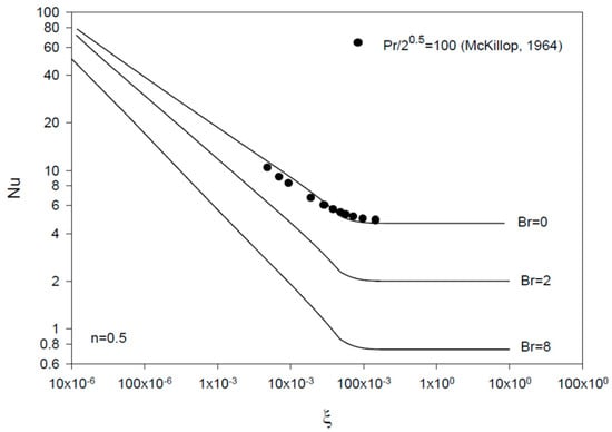
Figure 7.
Profiles of Nu vs. ξ = x/(R Re Pr) for Br = 0, 2, and 8 (n = 0.5). The results are compared with those of McKillop [25].
The thermal entrance region length (in dimensionless form, ξe) is defined as the axial distance where Nu reaches 1.05 times the asymptotically reached value for the Nusselt number [15]. Figure 8 and Figure 9 show that the dimensionless thermal inlet region size ξi is clearly smaller than the thermal entrance region size ξe, with both ξi and ξe increasing at higher Br values. ξe is found to increase and ξi to decrease at higher n values in consistency with the results for the dimensionless boundary layer thickness profiles. The results for the boundary layer thickness show decreasing values with increasing n and increasing Brinkman number, Br, with more effect of Br on at larger n values (Figure 10, Figure 11 and Figure 12).
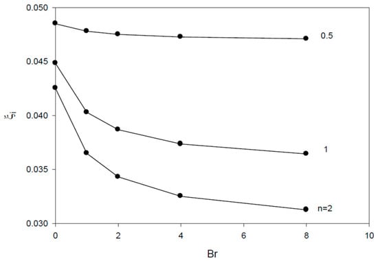
Figure 8.
Profiles of dimensionless thermal inlet region size vs. Br for n = 1, 2, and 0.5.
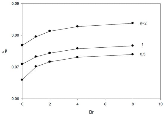
Figure 9.
Profiles of dimensionless thermal entrance region size vs. Br for n = 1, 2, and 0.5.
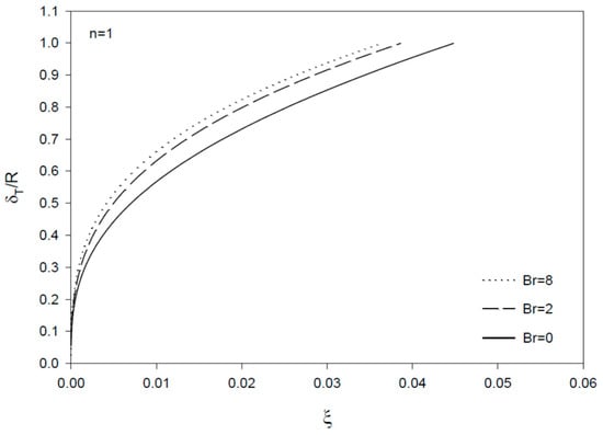
Figure 10.
Profiles of dimensionless thermal boundary layer thickness vs. ξ = x/(R Re Pr) for Br = 0, 2, and 8 (n = 1, Newtonian fluid).
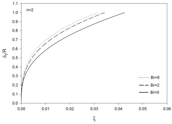
Figure 11.
Profiles of dimensionless thermal boundary layer thickness vs. ξ = x/(R Re Pr) for Br = 0, 2, and 8 (n = 2).
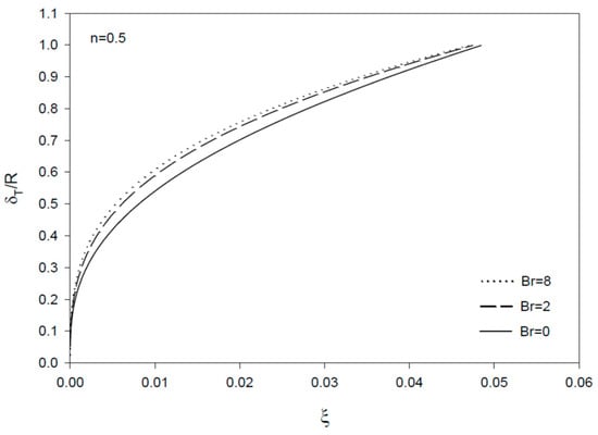
Figure 12.
Profiles of dimensionless thermal boundary layer thickness vs. ξ = x/(R Re Pr) for Br = 0, 2, and 8 (n = 0.5).
The profiles for the thermal shape factor, ΓT, are provided in Figure 13, Figure 14 and Figure 15. ΓT is zero in the inlet region.
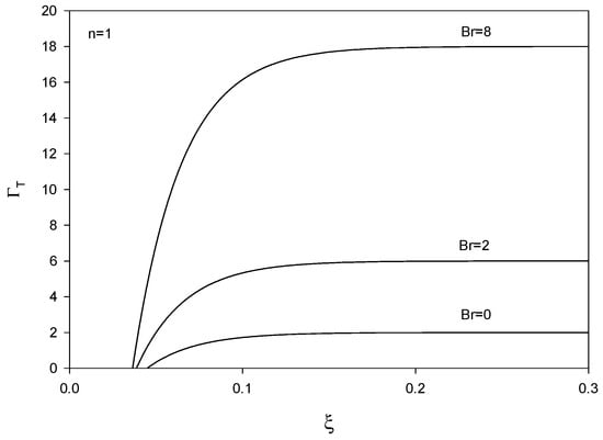
Figure 13.
Profiles of thermal shape factor vs. ξ = x/(R Re Pr) for Br = 0, 2, and 8 (Newtonian fluid).
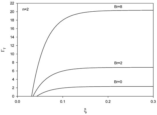
Figure 14.
Profiles of thermal shape factor vs. ξ = x/(R Re Pr) for Br = 0, 2, and 8 (n = 2).
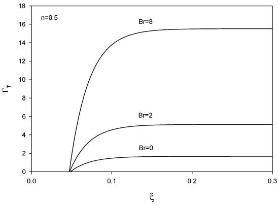
Figure 15.
Profiles of thermal shape factor vs. ξ = x/(R Re Pr) for Br = 0, 2, and 8 (n = 0.5).
As mentioned in the introduction, the formal solution for the isoflux Graetz problem in [8] applies to the case of negligible viscous dissipation. The formal solution in [10] includes viscous dissipation considered as a function of radial coordinates, Eigen functions, and Eigen values, with the problem solved numerically in the case of small viscous dissipation [10]. The present work provides a new method for a solution requiring minimum computational work and providing new results for the isoflux Graetz–Brinkmann problem (viscous dissipation effects included).
5. Conclusions
- The present model for developing heat transfer and developed power-law fluid flow in a heated tube subject to a uniform flux (isoflux Graetz–Brinkman problem) is based on the inlet-filled region concept and accounts for viscous dissipation.
- An integral method is used in the two regions forming the thermal entrance region: a thermal inlet region where the thermal boundary layer develops, and a thermally filled region where the centerline temperature keeps changing with thermal effects occurring in the whole tube cross section.
- The results include profiles for the dimensionless wall, bulk, and center line temperatures, Nusselt number, boundary layer thickness, and thermal shape factor, in addition to the dimensionless thermal inlet and entrance regions lengths for different values of the power-law index and Brinkman number.
- The model provides new and extensive results for the Graetz–Brinkman problem (Br ≠ 0) for power-law fluid flow in a tube subject to uniform heating flux and uniform inlet temperature. The model is validated against available published results (Br = 0 case) in Figure 2, Figure 3, Figure 5 and Figure 7 and the derived fully developed solution (expressions for fully developed values for the Nusselt number and thermal shape factor in Section 3.2 and dimensionless centerline temperature gradient in Section 4).
- The model can be used to estimate the entrance region length and evaluate temperature profiles in order to prevent fluid overheating in tubes subject to uniform heating and viscous dissipation.
- The computational task required using the present model is minimal as the model is essentially analytical.
- The present model applies to developing heat transfer for fully developed laminar power-law fluid flow in the case of uniform heating flux at the wall and uniform inlet temperature. Since the model is based on boundary layer theory, and axial conduction effects are neglected, the Reynolds and Peclet numbers are assumed sufficiently large. For large Prandtl numbers, the present solution can be considered as a good approximation for simultaneously developing power-law fluid flow and heat transfer, as the hydrodynamic entrance region length is significantly smaller than the thermal one at a large Prandtl number.
- Following the research works in [22,23], analysis and experimentation are recommended for nonisothermal heat transfer investigations including viscous effects to investigate solvability, uniqueness of solution, and stability. Further studies can also provide data for comparison with the present model in the case where viscous dissipation cannot be neglected. To the author’s knowledge, the published results are limited to one reference [18], where Re = 500 and Pr = 10 for the different problem of simultaneously developing power-law fluid flow and heat transfer, in which case the present model can represent a good approximation subject to the requirement of a large Prandtl number for the abovementioned reason.
Funding
This research was funded by the American University of Sharjah-grant number FRG23-E-E45.
Data Availability Statement
The references for the results used for comparison with the present work are provided in the paper.
Acknowledgments
Thanks are due to the American University of Sharjah for funding the research project.
Conflicts of Interest
The authors declare that they have no known competing financial interests or personal relationships that could have appeared to influence the work reported in this paper.
Nomenclature
| A | Constant defined in Equation (18) |
| B | Constant defined in Equation (18) |
| b0 − b4 | Approximate temperature profile coefficients |
| Br | Brinkman number, |
| cp | Specific heat capacity at constant pressure |
| C0, C2 | Fully developed temperature profile coefficients defined in Equation (19) |
| F | Defined in Equations (33) and (39) |
| g | Defined in Equations (32) and (38) |
| h | Convective heat transfer coefficient |
| I | Integrals defined in Equation (35) |
| k | Fluid thermal conductivity |
| K | Power-law fluid consistency index |
| n | Power-law fluid index |
| Nu | Nusselt number |
| p | q + 2 |
| P | Pressure |
| Pr | Prandtl number defined in Equation (13) |
| Pe | Re Pr |
| q | 1 + (1/n) |
| q0 | Uniform heat flux at the wall |
| r | Radial coordinate |
| R | Inner radius of the tube |
| Re | Reynolds number |
| T | Temperature |
| T0 | Entrance temperature |
| Tc | Centerline temperature |
| Tw | Temperature at the wall |
| Tb | Bulk temperature |
| Dimensionless temperature, | |
| Dimensionless fully developed temperature defined in Equation (18) | |
| T* | Dimensionless temperature, |
| u | Velocity axial component |
| u/Uc | |
| Uc/U0 | |
| U0 | Entrance velocity |
| v | Velocity radial component |
| x | Axial coordinate |
| y | Distance from the wall |
| Greek letters | |
| α | Thermal diffusivity, k/(ρcp) |
| ξ | Dimensionless x defined in Equation (12), x/(R Re Pr) |
| ξf | Dimensionless axial coordinate marking the beginning of the filled region, (x − xf)/(R Re Pr) |
| ηT | y/δT |
| ΓT | Thermal shape factor |
| ρ | Fluid density |
| ε | r/R |
| χ | Dimensionless axial distance defined in Equation (15) |
| δT | Thermal boundary layer thickness |
| Dimensionless thermal boundary layer thickness, δT/R | |
| θ | Dimensionless wall temperature, (T − T0)/(q0R/k) |
| Subscripts | |
| b | Bulk |
| c | Centerline |
| fd | Fully developed |
| f | Beginning of the filled region |
| w | Wall |
| ∞ | Core zone in the thermal inlet region |
References
- Manglik, R.M.; Prusa, J. Viscous Dissipation in Non-Newtonian Flows: Implications for the Nusselt Number. J. Thermophys. Heat Transf. 1995, 9, 733–742. [Google Scholar] [CrossRef]
- Bird, R.; Stewart, W.; Lightfoot, E. Transport Phenomena, 2nd ed.; John Wiley and Sons: New York, NY, USA, 2007. [Google Scholar]
- Mandapati, M.J.K. Effect of axial conduction and viscous dissipation on heat transfer for laminar flow through a circular pipe. Perspect. Sci. 2016, 8, 61–65. [Google Scholar] [CrossRef][Green Version]
- Khan, M.W.S.; Ali, N. Thermal entry flow of power-law fluid through ducts with homogeneous slippery wall(s) in the presence of viscous dissipation. Int. Commun. Heat Mass Transf. 2021, 120, 105041. [Google Scholar] [CrossRef]
- Siegel, R.; Sparrow, E.M.; Hallman, T.M. Steady laminar heat transfer in a circular tube with prescribed wall heat flux. Appl. Sci. Res. 1958, 7, 386–392. [Google Scholar] [CrossRef]
- Salazar, A.; Campo, A.; Schuler, C. On a solution of the Graetz-Nusselt problem and its extension with uniform wall heating. Heat Mass Transf. 1988, 22, 141–146. [Google Scholar] [CrossRef]
- Ou, J.W.; Cheng, K.C. Viscous dissipation effects on thermal entrance region heat transfer in pipes with uniform wall heat flux. App. Sci. Res. 1973, 28, 289–301. [Google Scholar] [CrossRef]
- Bird, R.B. Zur Theorie des Wärmeübergangs an nicht-Newtonsche Flüssigkeiten bei laminarer Rohrströmung. Chem. Ing. Tech. 1959, 31, 569–572. [Google Scholar] [CrossRef]
- Lyche, B.C.; Bird, R.B. The Graetz-Nusselt problem for a power-law non Newtonian fluid. Chem. Eng. Sci. 1956, 6, 35–41. [Google Scholar] [CrossRef]
- Cotta, R.M.; Özişik, M.N. Laminar forced convection to non-Newtonian fluids in ducts with prescribed wall heat flux. Int. Commun. Heat Mass Transf. 1986, 13, 325–334. [Google Scholar] [CrossRef]
- Khellaf, K.; Lauriat, G. A new analytical solution for heat transfer in the entrance region of ducts: Hydrodynamically developed flows of power-law fluids with constant wall temperature. Int. J. Heat Mass Transf. 1997, 40, 3443–3447. [Google Scholar] [CrossRef]
- ValkÓ, P.P. Solution of the Graetz–Brinkman problem with the Laplace transform Galerkin method. Int. J. Heat Mass Transf. 2005, 48, 1874–1882. [Google Scholar] [CrossRef]
- Barletta, A.; Magyari, E. Forced convection with viscous dissipation in the thermal entrance region of a circular duct with prescribed wall heat flux. Int. J. Heat Mass Transf. 2007, 50, 26–35. [Google Scholar] [CrossRef]
- Dehkordi, A.M.; Memari, M. Transient and steady-state forced convection to power-law fluids in the thermal entrance region of circular ducts: Effects of viscous dissipation, variable viscosity, and axial conduction. Energy Convers. Manag. 2010, 51, 1065–1074. [Google Scholar] [CrossRef]
- Al-Ali, H.H.; Selim, M.S. Analysis of laminar flow forced convection heat transfer with uniform heating in the entrance region of a circular tube. Can. J. Chem. Eng. 1992, 70, 1101–1107. [Google Scholar] [CrossRef]
- Chebbi, R.; Al-Ali, H.H.; Selim, M.S. Simultaneously developing laminar flow and heat transfer in the entrance region of a circular tube with constant wall temperature. Chem. Eng. Commun. 1997, 160, 59–70. [Google Scholar] [CrossRef]
- Hassan, M.F.; Chebbi, R. Analysis of heat transfer for simultaneously developing temperature profile and fluid flow of power-law fluids in the entrance region of a tube. Int. J. Thermofluids 2022, 16, 100240. [Google Scholar] [CrossRef]
- Etemad, S.G. Heat Transfer to Viscous Non-Newtonian FIuids in Non-Circular Ducts. Ph.D. Thesis, McGilI University, Montreal, QC, Canada, 1995. [Google Scholar]
- Ishizawa, S. The Axi-Symmetric Laminar Flow in an Arbitrarily Shaped Narrow Gap: (2nd Report, Theoretical Analysis for the Downstream Region). Bull. JSME 1966, 9, 86–103. [Google Scholar] [CrossRef]
- Mohanty, A.K.; Asthana, S.B.L. Laminar flow in the entrance region of a smooth pipe. J. Fluid Mech. 1979, 90, 433–447. [Google Scholar] [CrossRef]
- Chebbi, R. Laminar flow of power-law fluids in the entrance region of a pipe. Chem. Eng. Sci. 2002, 57, 4435–4443. [Google Scholar] [CrossRef]
- Baranovskii, E.S. The stationary Navier–Stokes–Boussinesq system with a regularized dissipation function. Math. Notes 2024, 115, 670–682. [Google Scholar] [CrossRef]
- Baranovskii, E.S.; Shishkina, O.Y. Generalized Boussinesq system with energy dissipation: Existence of stationary solutions. Mathematics 2024, 12, 756. [Google Scholar] [CrossRef]
- Press, W.; Flannery, B.; Teukolsky, S.; Vetterling, W. Numerical Recipes in FORTRAN 77: The Art of Scientific Computing, 2nd ed.; Cambridge University Press: Cambridge, UK, 1986. [Google Scholar]
- McKillop, A.A. Heat transfer for laminar flow of non-Newtonian fluids in entrance region of a tube. Int. J. Heat Mass Transf. 1964, 7, 853–862. [Google Scholar] [CrossRef]
Disclaimer/Publisher’s Note: The statements, opinions and data contained in all publications are solely those of the individual author(s) and contributor(s) and not of MDPI and/or the editor(s). MDPI and/or the editor(s) disclaim responsibility for any injury to people or property resulting from any ideas, methods, instructions or products referred to in the content. |
© 2025 by the author. Licensee MDPI, Basel, Switzerland. This article is an open access article distributed under the terms and conditions of the Creative Commons Attribution (CC BY) license (https://creativecommons.org/licenses/by/4.0/).