1. Introduction
The need to increase the energy efficiency of heating devices and reduce their impact on the environment requires searching for new, ecologically friendly, and cheaper solutions. Natural gas, so far considered one of the most effective fuels, comes from non-renewable sources, so it is necessary to look for its substitutes. The solution may include, among others, the use of hydrogen as an ecological energy carrier and fuel for devices heating low- and zero-energy houses [
1].
Currently, technologies using hydrogen are relatively expensive, but they are constantly being developed, and prices may in the future reach a level that will allow for a return on investment. Hydrogen is used in the chemical industry as a raw material for the synthesis of basic products (ammonia, hydrogen chloride, methanol, and synthetic gasoline and for carrying out reduction processes) [
2]. It plays an important role in the textile, pharmaceutical, tanning, and confectionery industries for the production of plastics. The increasing use of hydrogen in recent years can be seen in the transport industry as a fuel for cars, trains, planes, drones, and ships. Hydrogen is burned directly in engines or in fuel cells that generate electricity [
3]. It has emerged as a key element in the transition to sustainable energy systems due to its clean-burning properties [
4], high energy density [
5], and versatility as an energy carrier [
6,
7]. As global efforts to mitigate climate change intensify, hydrogen is finding more uses in a wide array of applications, including fuel cells [
8,
9,
10], industrial heat generation [
11,
12], and as a substitute for fossil fuels in high-temperature processes [
13,
14]. Its combustion produces water as the sole byproduct, making this element environmentally friendly [
15]. However, achieving efficient, reliable, and scalable hydrogen-based energy solutions remains a critical challenge, particularly in thermal energy recovery applications where waste heat utilization is essential.
Conventional hydrogen combustion technologies often suffer from significant energy losses and inefficient heat transfer mechanisms, limiting their feasibility for large-scale deployment [
3,
16,
17]. The use of a flame burner to burn fuels is associated with high NO
x emissions [
15,
18] and the risk of flashback [
19]. A low-temperature catalytic combustion has been explored as a promising solution to these limitations. The absence of flame means fire safety as well as a reduction in pollutant emissions [
18,
20,
21,
22,
23].
By enabling the controlled oxidation of hydrogen at relatively low temperatures, catalytic systems reduce the formation of nitrogen oxides (NO
x) and enhance the overall energy recovery efficiency [
24,
25]. Among these, palladium-based catalytic systems have been widely studied due to their high catalytic activity and resistance to sintering at elevated temperatures [
22,
26,
27]. For instance, Specchia et al. [
28] described the catalytic combustion of methane, hydrogen, and air mixtures in microscale channels using a 2% Pd on a 5% LaMnO₃·ZrO₂ (PLZ) catalyst supported on silicon carbide (SC) or cordierite (CD) monoliths. Palladium, as the key component of the catalyst, played a significant role in the combustion process, showing high activity in methane oxidation and facilitating catalytic ignition with the assistance of hydrogen. The experiments were conducted in a laboratory microscale reactor designed to optimize the combustion process under high power density conditions (7.6 MWth m⁻³; GHSV 16,000 h⁻¹). The results of the conducted experiments demonstrated that the use of palladium significantly reduced ignition temperatures and enabled stable combustion conditions. In other work [
29], catalytic hydrogen combustion (CHC) as a clean and efficient energy generation technology for hydrogen-powered systems, such as fuel cells, has been described. The research focused on Pd-Cu/Al
2O
3 catalysts at low temperatures (<125 °C) and demonstrated the pivotal role of palladium in the process. Higher reduction temperatures facilitated the formation of metallic Pd, significantly enhancing catalytic activity, particularly at the optimized composition of Pd
0.75Cu
0.25/Al
2O
3. Palladium played the role of the primary active component, enabling efficient adsorption and reaction of hydrogen and oxygen molecules on the catalyst surface. It was clearly shown that the Langmuir–Hinshelwood mechanism, based on single active sites, best described the hydrogen combustion process, emphasizing the importance of the proper distribution and availability of palladium within the catalyst structure.
Importantly, theoretical analyses have also been performed to better understand the mechanisms underlying catalytic processes and the impact of catalyst structure on performance. For instance, Qi et al. [
30] employed density functional theory to investigate the mechanisms of hydrogen catalytic combustion on palladium surfaces. They compared two models: a Pd(111) slab representing larger palladium surfaces and a Pd
38 cluster simulating smaller palladium nanoparticles. The findings revealed that the Pd
38 cluster exhibited a lower activation energy barrier for hydrogen oxidation compared to the Pd(111) slab, indicating that smaller palladium particles may enhance catalytic activity in hydrogen combustion processes.
Many previous studies have focused on the design of catalytic reactors for oxidation and combustion processes to ensure optimal performance and process stability. An example of such work is [
31], which highlights the critical importance of geometric configuration, material selection, and thermal management in catalytic reactor design. The authors emphasize that uniform temperature distribution and controlled gas flow are essential to maintaining consistent catalytic activity throughout the bed. Advanced design strategies, such as the use of structured catalytic layers or monolithic supports, are also described. These approaches aim to enhance mass and heat transfer while minimizing pressure drop and energy losses. Such methods improve the utilization of active components, such as palladium, and contribute to the more efficient operation of the system. In turn, in the work by Kim et al. [
32], the importance of reactor design in hydrogen catalytic processes, particularly for palladium-based systems, has been discussed. The authors demonstrated that optimizing reactor geometry and operational parameters ensures effective heat and mass transfer. These factors are critical for uniform catalytic activity and stability. Structured supports and tailored activation conditions are shown to reduce pressure drops and improve active component utilization, emphasizing the strong influence of reactor design on performance and sustainability in hydrogen applications. In another paper [
33], the authors indicated the significance of maintaining uniform temperature profiles, with temperature variations limited to ±5 K, ensuring efficient gas flow distribution to prevent hot spots and inactive regions. The research demonstrated that optimizing the reactor geometry and flow rates, up to 1000 mL/min, enhances heat and mass transfer while minimizing energy losses. Advanced strategies, such as monolithic supports and precise control of activation conditions, improve catalytic efficiency by up to 25% and reduce operational instabilities, underscoring the critical role of reactor design in achieving sustainable and high-performance hydrogen systems.
The main objective of performed tests was to eliminate the use of pure oxygen and instead utilize air as an oxygen source, thereby minimizing the risk of explosion in potentially hazardous mixtures. Firstly, a prototype single-bed system was developed. The catalytic bed was activated thermally, with the process monitored using a thermal imaging camera to observe the initiation and development of working temperatures, which depended on the hydrogen flow. Following this, a multi-bed heat generator system was designed and implemented to enhance performance and scalability. Temperature measurements of water, exhaust gases, and system power output were performed under various hydrogen flow rates to evaluate the efficiency and operational stability of the system.
2. Materials and Methods
2.1. Materials
The catalytic bed was prepared using ceramic fibers ECONO 1260T 300 (IZO Zakład Izolacji Ogniotrwałych Sp. z o.o., Bytom, Poland), which are characterized by high thermal and mechanical strength, making them suitable for use as catalyst carriers in high-temperature applications. Palladium (II) chloride (CAS #7647-10-1, minimum purity 99.9%) and sodium chloride used for catalyst preparation were purchased from Thermo Fisher Scientific (Waltham, MA, USA). Hydrogen (technical grade) used as a reactant for catalytic combustion was bought from Air Liquide Polska Sp. z o.o. (Kraków, Poland).
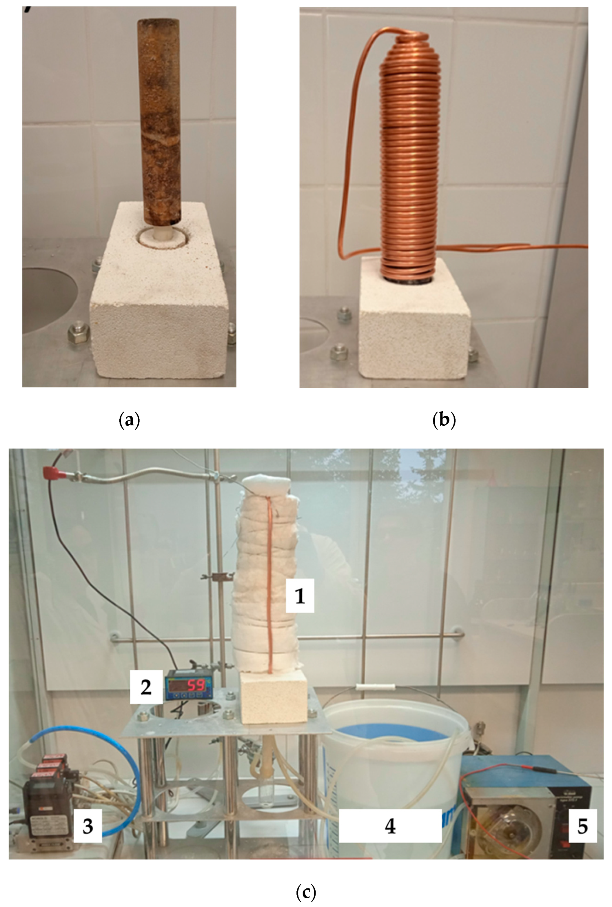
2.2. Development of the Single Catalytic Bed Heat Removal System
In order to perform preliminary performance tests of the catalytic bed, a heat recovery system from a single bed was constructed. The catalyst carrier was made of ECONO 1260T 300 ceramic fiber material in the form of a hollow cylinder (length: 20 cm, outer diameter: 4 cm, inner diameter: 2 cm), which was additionally impregnated with a 0.03 M palladium chloride solution. A copper coil with an outer diameter of 6 mm was applied as the heat receiver, while the system was sealed with thermal insulation fiberglass wool. Tap water was used as the cooling medium and supplied through a peristaltic pump (Eplan Laboratory Instruments, Katowice, Poland) at a flow rate of 0.3 dm
3/min. The temperature of the water was measured at both the inlet and outlet points. The homogeneous distribution of the fuel mixture was ensured through the design of the gas supply system, which incorporated a controlled flow of hydrogen and air to promote uniform mixing before reaching the catalytic beds. The system was designed to minimize concentration gradients and ensure consistent reactant delivery across the entire reaction zone. The scheme of the single catalytic bed system is presented below in
Figure 1.
The combustion experiments were conducted in a controlled environment equipped with an EDG-7K gas detector (Figaro Engineering Inc., Osaka, Japan), which was capable of detecting hydrogen at concentrations below 1 ppm. The detector was used to verify both system tightness and combustion efficiency by continuously monitoring for unburned hydrogen. The absence of detectable hydrogen leaks confirmed complete combustion and ensured the safe operation of the setup.
Before use, the catalytic bed required activation, which is described in detail in the following subsection of this paper.
2.3. Activation of the Catalytic Bed
The activation of the catalytic bed involved the reduction in palladium complexes deposited on the catalyst carrier and the subsequent formation of metallic palladium on its surface. For this purpose, a hydrogen–air mixture containing 4% hydrogen was employed. The process was conducted until the complete catalytic combustion of hydrogen was achieved throughout the entire volume of the bed. To verify the complete combustion of hydrogen, a hydrogen detector was placed near the reduced bed. The moment of complete palladium reduction in the catalytic bed was determined by the absence of hydrogen in the exhaust gases from the bed.
The primary goal of this activation process was to prepare the catalyst for efficient performance by ensuring the presence of active palladium sites, which are crucial for catalytic reactions. During the activation of the bed, temperature monitoring was conducted using a True RMS digital multimeter equipped with Benning PC-Win MM12 software, K-type thermocouples (BENNING Electrical and Electronic GmbH & Co. KG, Bocholt, Germany), and a thermal imaging camera (Topdon Technology, Ltd., Shenzhen, China, measuring range −20–550 °C) to observe the progression of the reduction process.
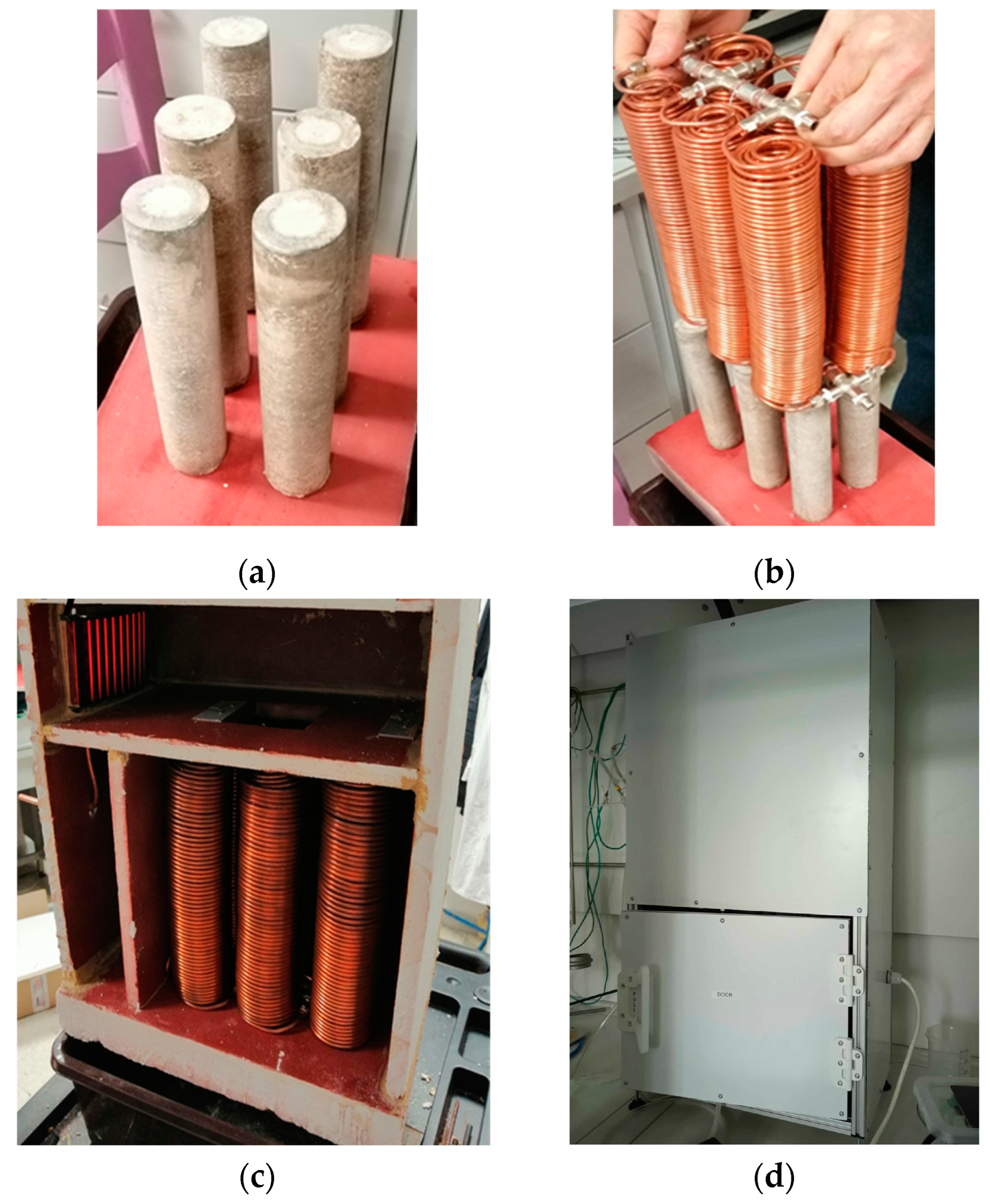
2.4. Development of a Multi-Bed Heat Generator System and Analysis of Its Thermal Efficiency
The multi-bed heat generator system was constructed using 6 parallel-connected, independent catalytic beds described previously in
Section 2.2 of the paper. The catalytic beds were mounted on a plate made of ECONO 1260T 300 ceramic fiber material with a thickness of 5 cm, providing thermal stability and gas tightness. The plate was additionally reinforced with an adhesive (Piecolep, ZAMAC Sp. z o.o., Kraków, Poland) and coated with high-temperature spray paint to enhance rigidity and insulation. The beds were then placed in a chamber constructed from plates of the same material and were also reinforced with an adhesive to improve gas tightness. The chamber served as an insulated enclosure for the system, minimizing heat loss and ensuring optimal operating conditions for the heat generator. In
Figure 2, the images of the successive phases of heat generator development are compiled.
The catalytic supply system was based on a central hydrogen–air gas mixer, in which a homogeneous fuel mixture with a composition of 4% hydrogen in air was prepared. The prepared mixture was evenly supplied to all 6 reactors. The homogeneous distribution of the fuel mixture was achieved analogously as in the case of a single-bed catalyst.
The power P required for heating the water in the developed system was determined using simultaneous temperature measurements of the water entering and exiting the system. The calculation was based on Equation (1) as follows:
where
is the specific heat capacity of water, 4.1806 ;
is the outlet water temperature, K;
is the inlet water temperature, K;
is the mass of water flowing through the system over time t.
The thermal efficiency can indeed be calculated using the obtained values in Equations (2) and (3) as follows:
where
η is thermal efficiency, %;
is the heat of heated water, K;
is the heat input based on tabulated values for the heat of combustion of hydrogen, ;
is the specific heat capacity of water, 4.1806 ;
is the water flow rate, 2000 mL/s;
is flow time, 350 s;
is cold water temperature, K;
is hot water temperature, K.
2.5. Methodology for Temperature Data Analysis
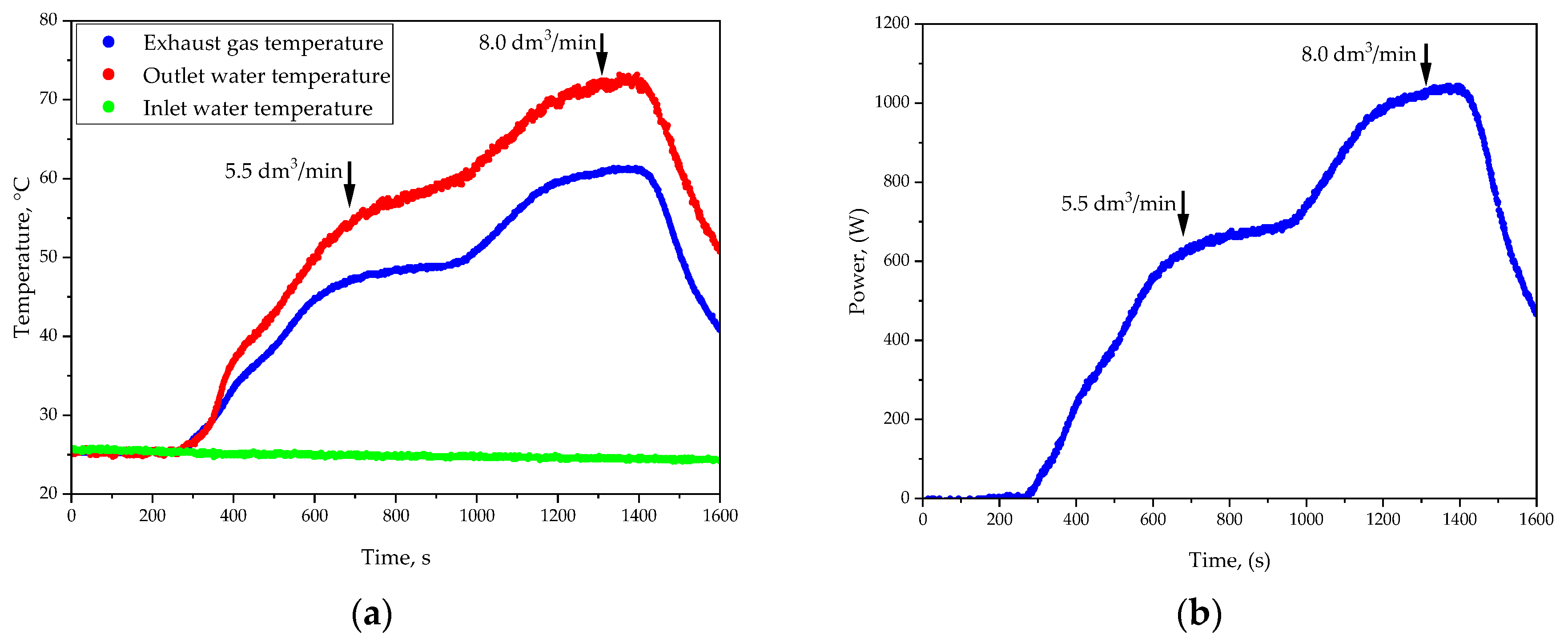
The aim of the temperature data analysis was to evaluate the thermal performance and stability of the heat generator under two hydrogen flow rates: 5.5 L/min and 8.0 L/min. The heat transfer medium flow rates were set at 0.300 L/min and 0.621 L/min, respectively, to match the thermal load for each condition, with a constant airflow rate of 110 L/min.
Temperature measurements were taken in real time using K-type thermocouples placed at the water inlet, outlet, and within the exhaust gas stream. A LabJack U6 device and DAQFactory software ensured simultaneous and precise data acquisition. The system was tested until thermal equilibrium was reached, indicated by the stabilization of the cooling water temperature.
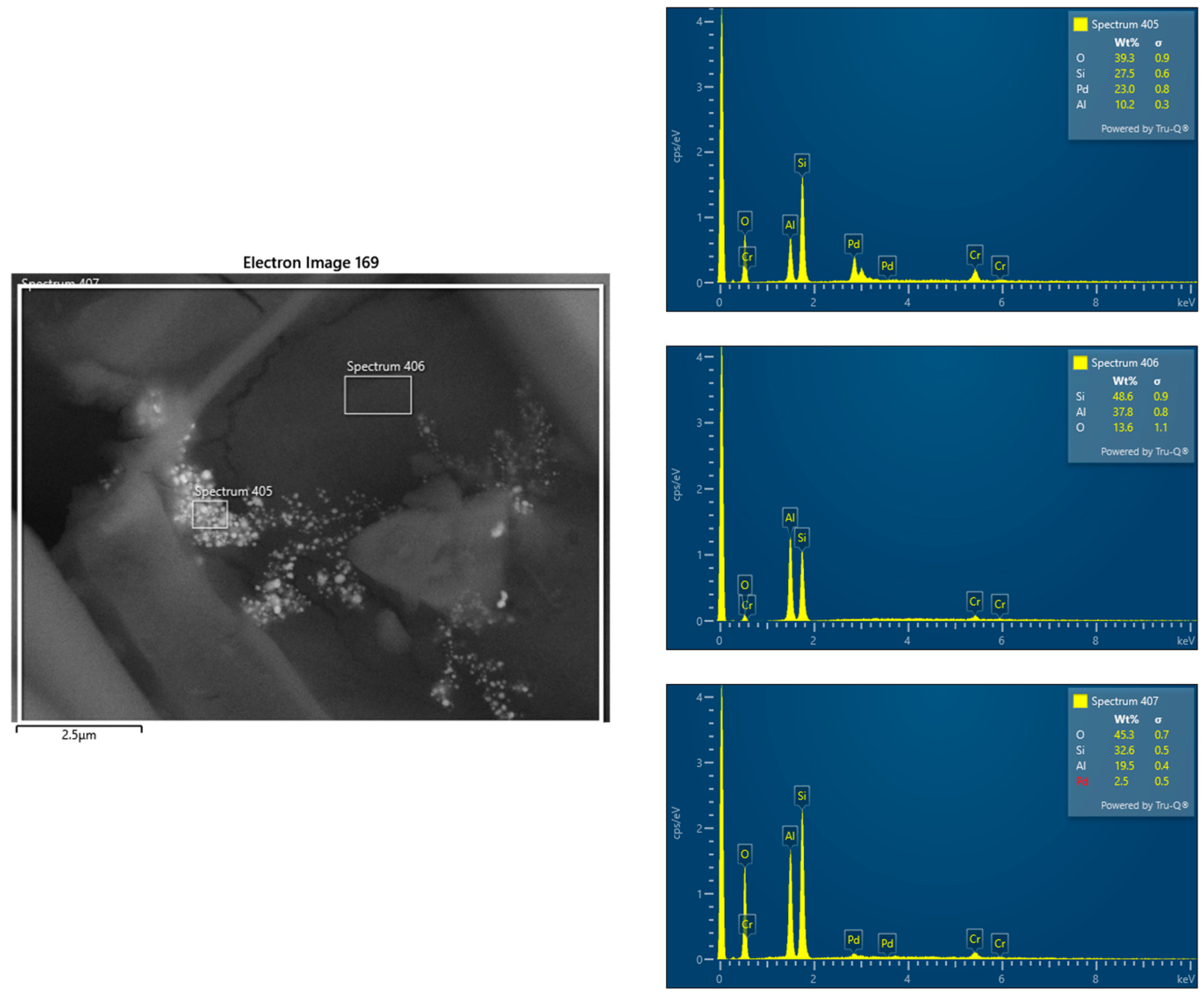
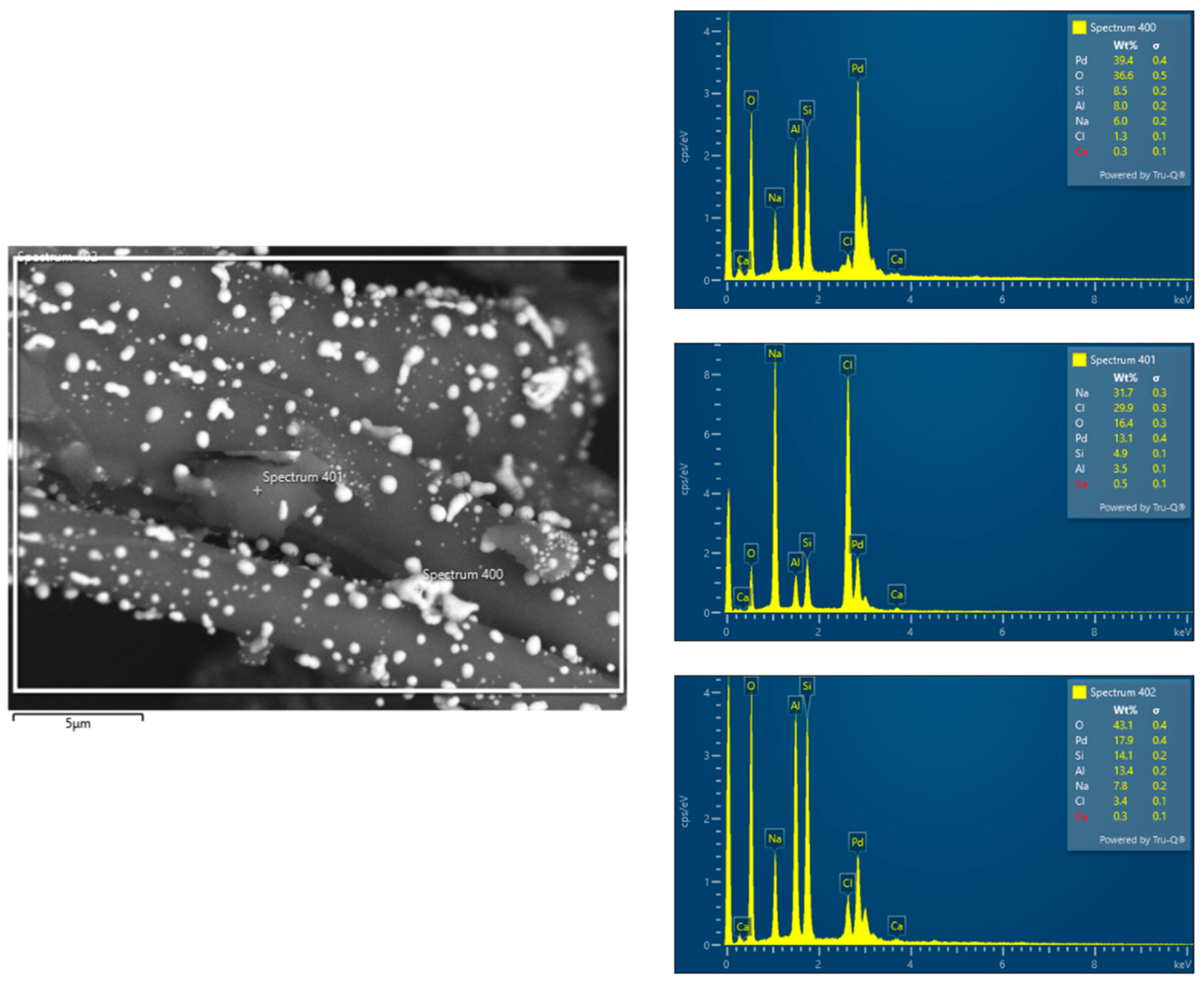
2.6. Characterization of a Catalyst Bed Using SEM-EDS Analysis
The surface morphology and composition were analyzed using a high-resolution scanning electron microscope, JEOL JSM-7500F, with an extra-INCA EDS PentaFETx3 system. A secondary electron imaging detector, SEI, mode was used to determine the catalyst morphology and particle distribution at the catalyst surface. For palladium particle imaging on the catalyst surface, a Back-Scattered Electron detector, BSE, was used.
4. Discussion
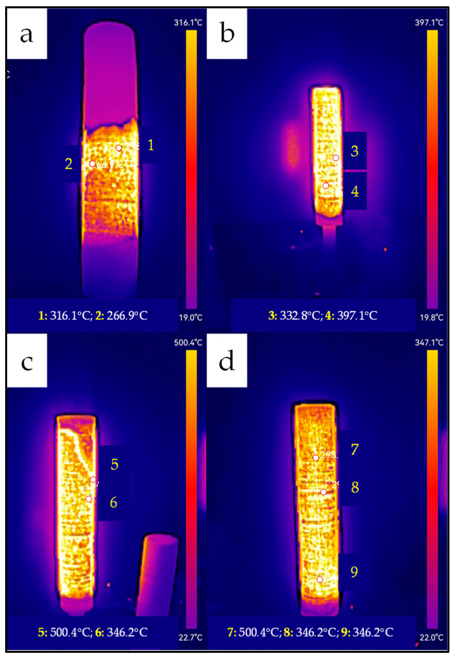
Catalytic combustion of hydrogen in a heat generator system requires full and homogeneous activation of the catalytic bed, a key step in preparing the system for proper operation. This process involves the reduction in palladium ions to metallic form, enabling the formation of active catalytic centers responsible for the efficient reaction performance. Achieving a uniform temperature distribution in the bed and controlling the course of the reduction process are essential to ensure the stability and performance of the system in subsequent applications. The reduction process of the palladium catalyst was monitored using a thermal imaging camera, which made it possible to observe temperature changes in real time and evaluate the progress of the reaction. The thermal images shown in
Figure 2 illustrate the successive stages of catalyst reduction at 3 min (
Figure 3a), 8 min (
Figure 3b), 10 min (
Figure 3c), and 12 min (
Figure 3d) after the start of the process.
At the beginning, after 3 min, a local zone of increased temperature (~316 °C) was observed, indicating the beginning of an intense reduction reaction and the formation of metallic palladium on the catalyst support. A small, concentrated zone of heat was visible in the thermal image. After 8–10 min, the high-temperature zone expanded significantly, covering most of the bed and reflecting the uniform spread of the reduction reaction front. The image obtained after 12 min already shows an even temperature distribution throughout the bed, which signified the completion of the process and full activation of the catalyst. The full reduction, confirmed by the homogeneity of the temperature distribution in
Figure 3d, guarantees high stability of the catalyst bed operation in the subsequent stages.
The analysis of catalyst reduction provides insights into system activation, while performance assessment under varying hydrogen flow rates demonstrates its thermal efficiency and stability.
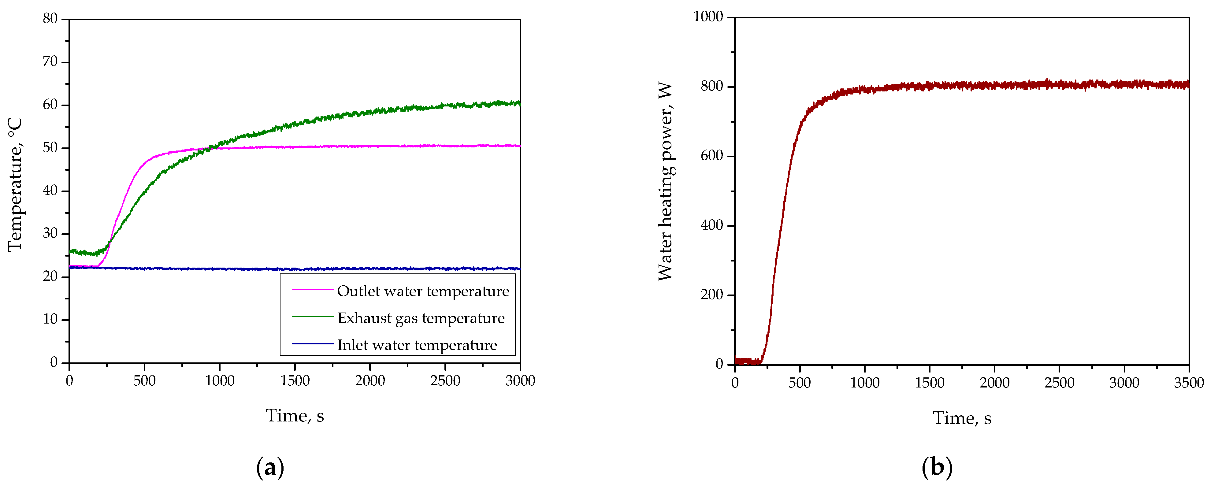
Figure 4 and
Figure 5 verify key parameters of the developed system over time. Discussing the results of the study performed at an H
2 flow rate of 5.5 L/min (
Figure 4), it may be observed that during the initial stage of the experiment, the exhaust gas temperature was relatively low, indicating that most of the generated heat was effectively retained within the system. This observation highlights the initial ability of the developed system to limit heat losses through exhaust gases, favoring the efficient utilization of thermal energy. As the experiment progressed, a steady increase in the cooling water temperature was observed, reaching stabilization after approximately 600 s. This demonstrates the system’s capability to effectively manage and extract heat generated through catalytic combustion. By the time the system reached thermal equilibrium—beyond 600 s—both the cooling water temperature and the exhaust gas temperature remained stable. The stable exhaust gas temperature suggests that the system design effectively directed the majority of the generated heat towards the cooling medium, minimizing unnecessary energy dissipation. The results obtained for the hydrogen flow rate of 5.5 L/min indicate a well-balanced system capable of efficiently retaining thermal energy while maintaining operational stability.
Considering the results of the experiment performed for the H2 flow rate of 8.0 L/min, it may be said that at the start of the experiment, the cooling water temperature rose more rapidly than in the case of 5.5 L/min configuration, thereby indicating the increased combustion intensity and the resulting higher heat generation. The exhaust gas temperature was notably higher during the initial phase, suggesting a more intense reaction and greater thermal energy release. However, this also indicates an increased potential for heat losses through the exhaust gases. By approximately 600 s, the system entered a phase of stabilized heat transfer dynamics. The cooling water temperature continued to rise but at a slower rate, indicating that most of the available thermal energy was being effectively transferred to the cooling medium. Simultaneously, the exhaust gas temperature maintained elevated levels compared to the 5.5 L/min configuration. As the system approached thermal equilibrium—beyond 600 s—the cooling water temperature began to stabilize, marking the point where the system’s heat extraction capacity matched the rate of heat generation. Despite this stabilization, the exhaust gas temperature remained higher than desired, highlighting the need for potential improvements in the system’s thermal insulation or the implementation of additional heat recovery measures. However, the elevated exhaust gas temperatures observed throughout the experiment demonstrate the need to address heat losses to maximize system efficiency. In summary, the results for the hydrogen flow rate of 8.0 L/min reveal a system capable of delivering substantial thermal power with a consistent and predictable heat transfer to the cooling medium. The observations around 600 s emphasize the system’s ability to handle higher thermal loads while maintaining operational stability.
The analysis of hydrogen flow rates (5.5 L/min and 8.0 L/min) reveals distinct thermal characteristics. At 5.5 L/min, the system exhibited high thermal retention and minimal heat losses, making it suitable for stable, low-energy applications. In contrast, 8.0 L/min provided higher thermal power but with increased exhaust gas temperatures and heat dissipation. As shown in
Figure 4 and
Figure 5, the 8.0 L/min configuration resulted in greater energy output but higher heat losses compared to 5.5 L/min.
SEM-EDS analysis conducted before and after the catalytic process confirmed an uneven palladium distribution in the catalyst bed. Prior to hydrogen combustion, Pd concentrations varied across the support, with some regions exhibiting higher Pd content while others showed lower deposition levels. This suggests that the impregnation process did not ensure uniform distribution, potentially due to variations in wetting, surface porosity, or interactions between Pd complexes and the support material.
After the catalytic process, the SEM-EDS results continued to indicate heterogeneity in Pd distribution. Differences in palladium content across various regions of the bed could influence catalytic activity and system stability. Areas with higher Pd concentrations may provide more active sites for hydrogen oxidation, while regions with lower Pd content could exhibit reduced catalytic efficiency. Additionally, localized variations in Pd dispersion may affect heat and mass transfer, potentially leading to temperature gradients, uneven reaction rates, and differing levels of catalyst utilization across the bed.
In the course of the conducted research, the useful power and system efficiency were also calculated (based on the formulas presented in
Section 2.4). For the stabilized hot water temperature, after approximately 30 min, the temperature difference was 29.5 K, corresponding to a P
1 value of 702.34 W. Considering the hydrogen flow rate of 5.5 L/min, the supplied power (P
2) was 980.83 W. The calculated system efficiency was 72%. The obtained value indicates a satisfactory energy conversion efficiency, which may result from the experimental conditions and system parameters.

 ,
, 
