
A Review on the Overall Performance of Metal Hydride-Based Hydrogen Storage Systems

 , ,
, ,  ,
,  ,
,  ,
, 
Abstract
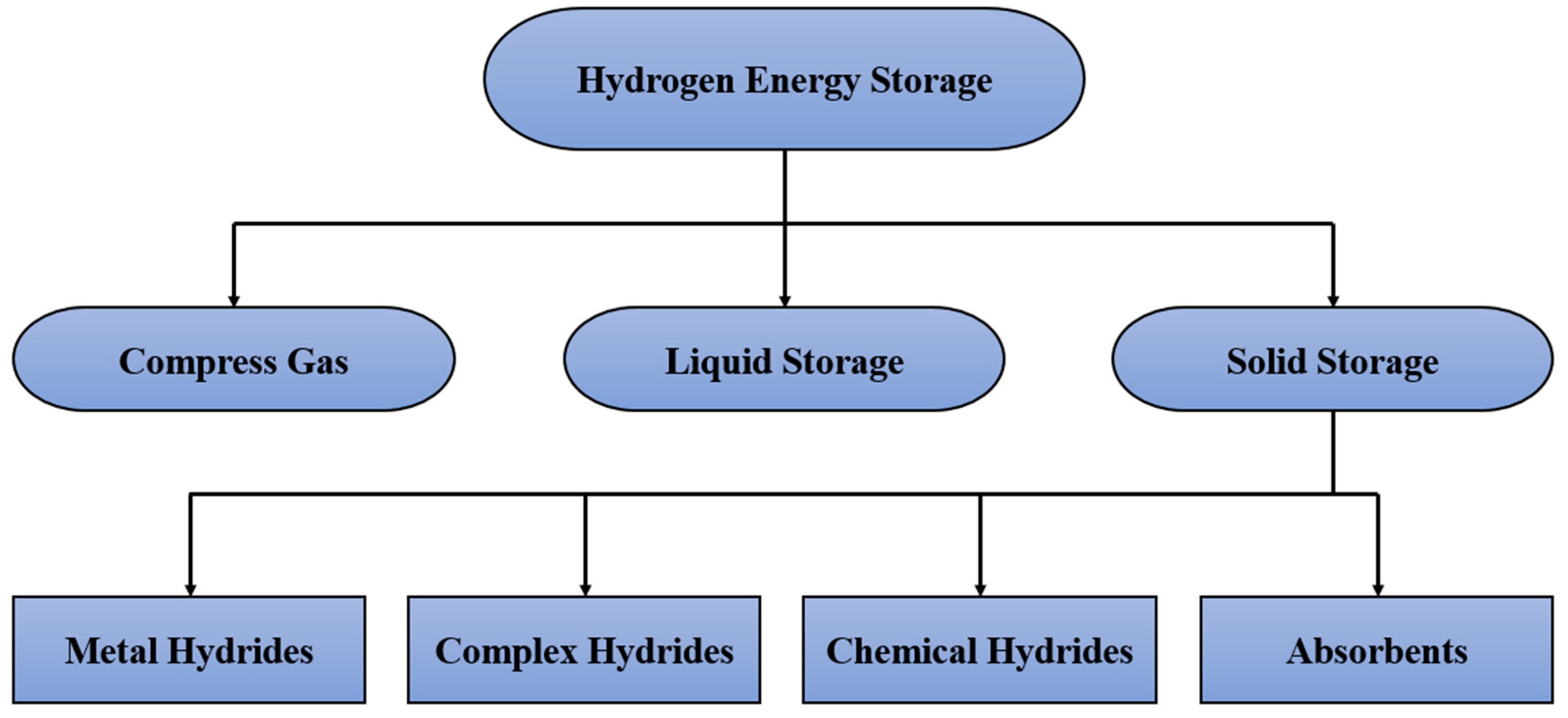
1. Introduction
- Complex hydrides and chemical hydrides: These two techniques are primarily used to store hydrogen by absorption. However, the main problems of these techniques are the lack of reversibility and the complexity of the reaction process to extract hydrogen [2].
- Absorbents: Porous materials are employed to absorb hydrogen. This technique provides better thermal management in the charging and discharging processes than other three techniques, including metal hydride, chemical hydride, and complex hydride [7]. However, this technique negatively affects storage capacity when focusing on large-scale commercialisation [8].
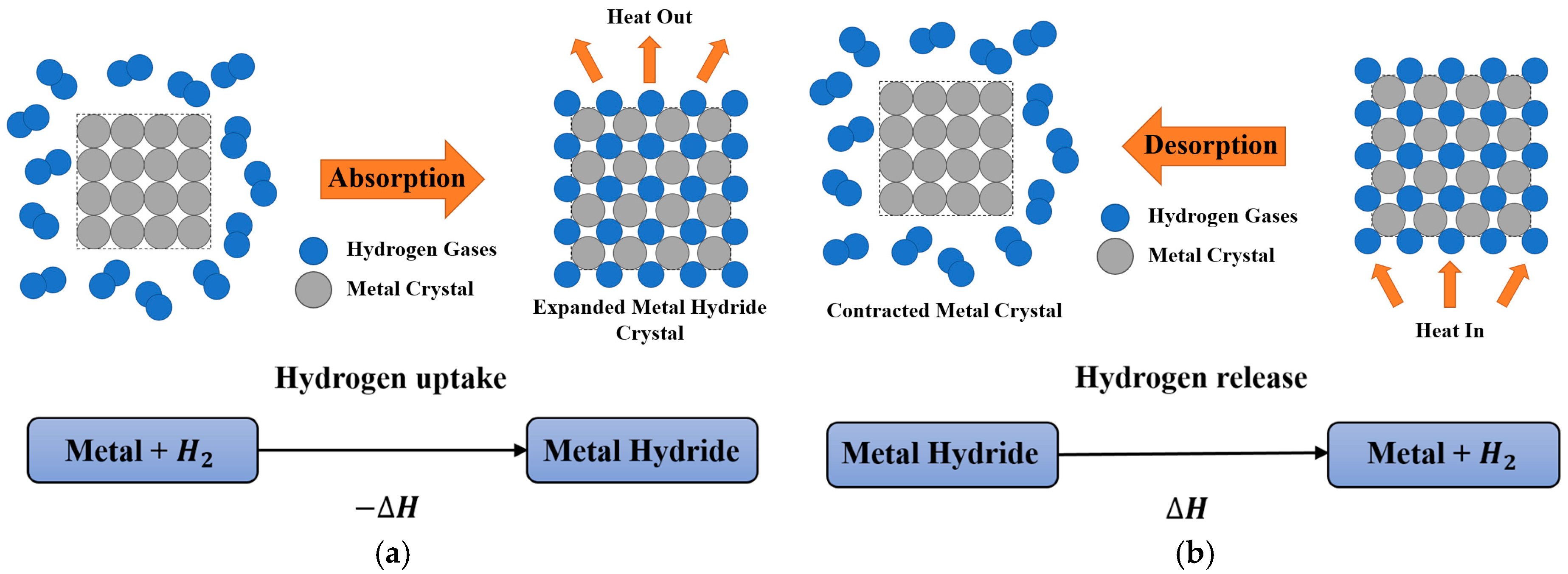
2. Metal Hydride Materials
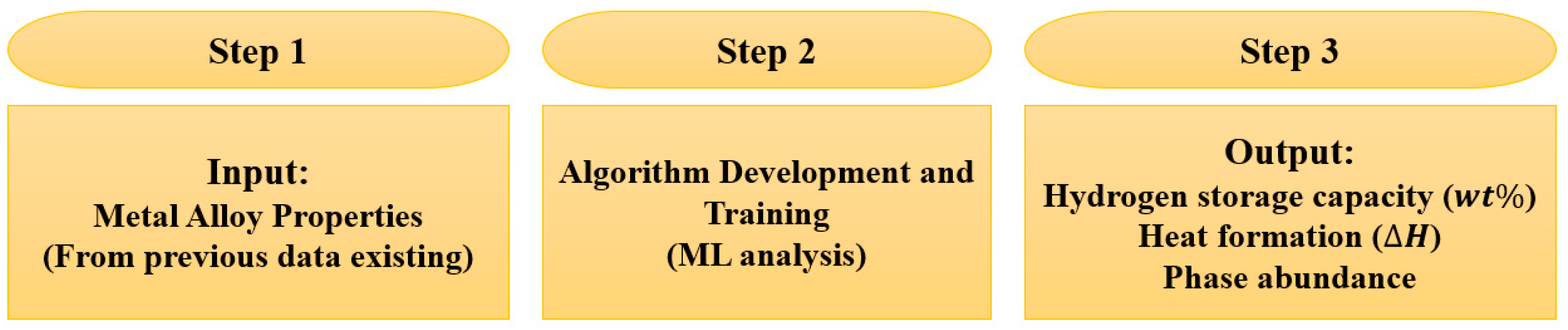
2.1. Machine Learning Techniques for Investigation of Metal Hydride Material Properties
2.2. Hydrogen Storage Capacity
2.3. Effective Thermal Conductivity
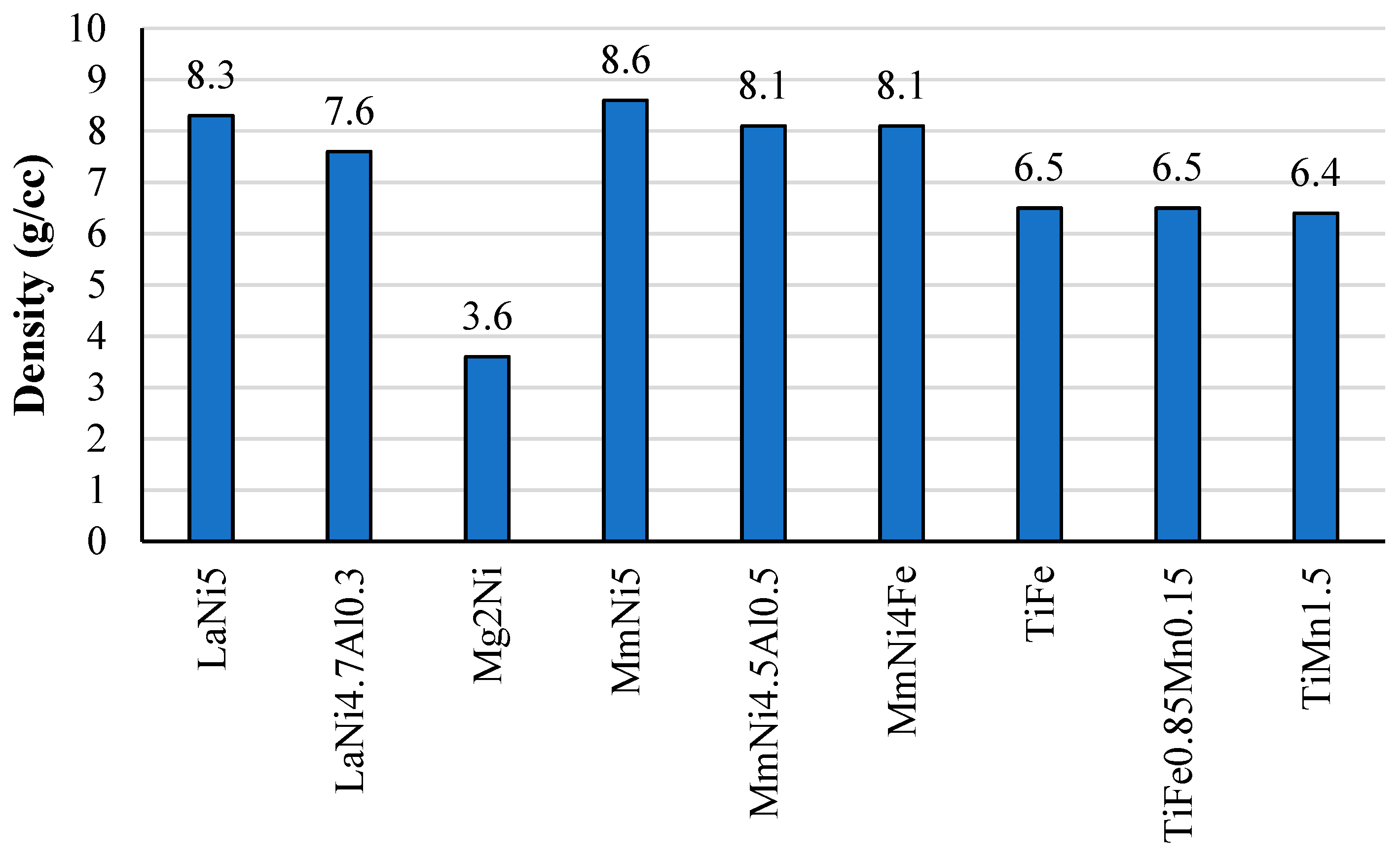
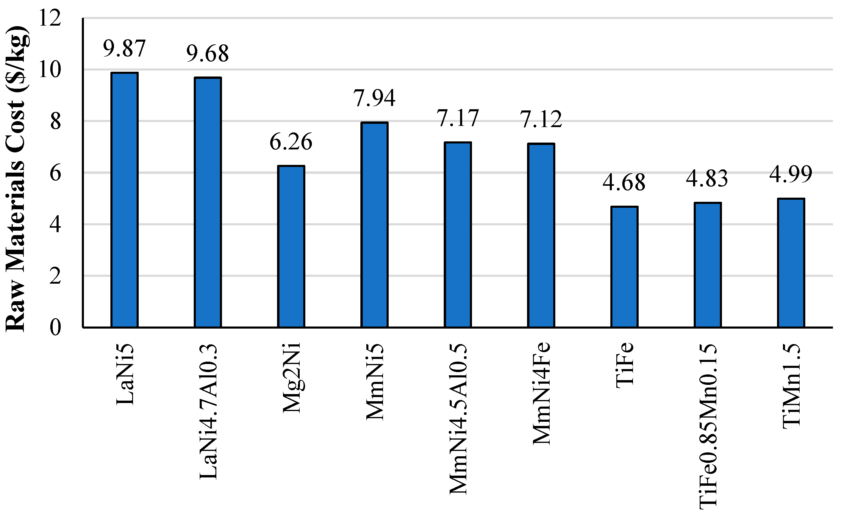
2.4. Density and Raw Cost Materials
3. Heat Exchanger Design Optimisation for Thermal Management
3.1. Design Optimisation for Active Thermal Management Method
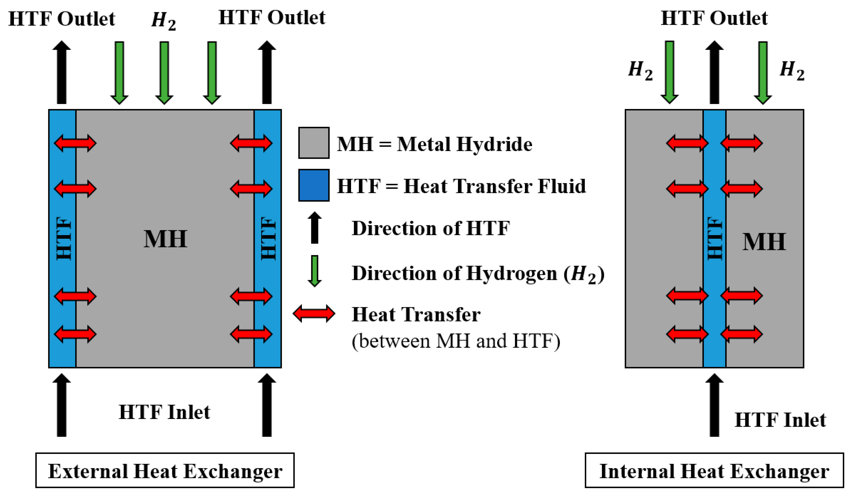
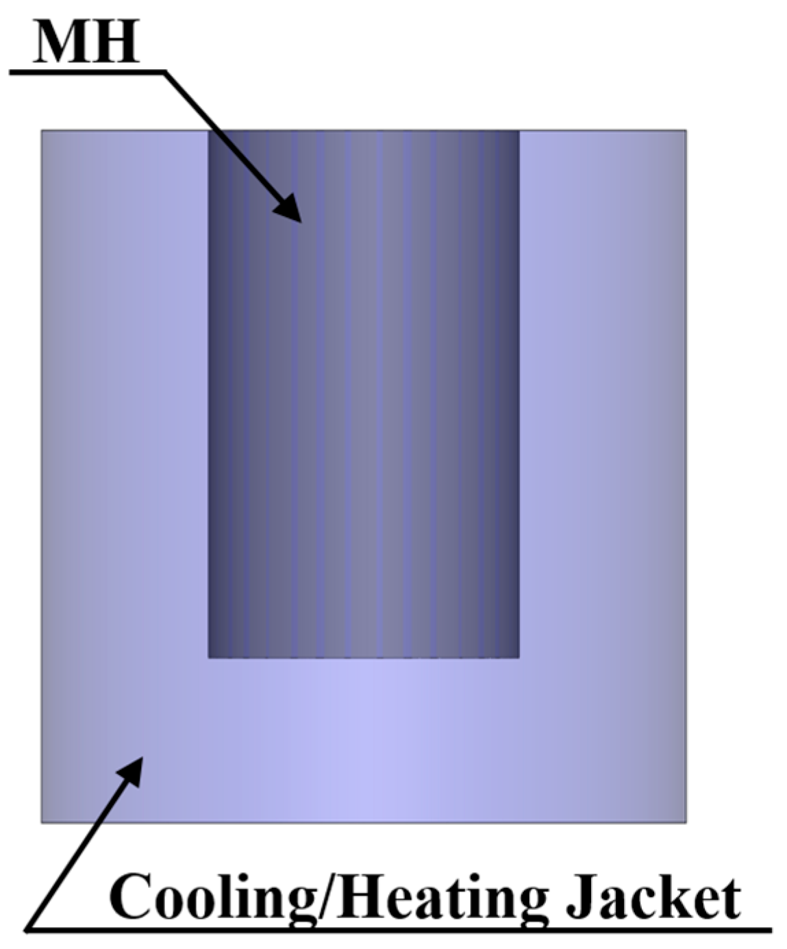
3.1.1. External Heat Exchanger
- Cooling/heat jacket
- Tube coil
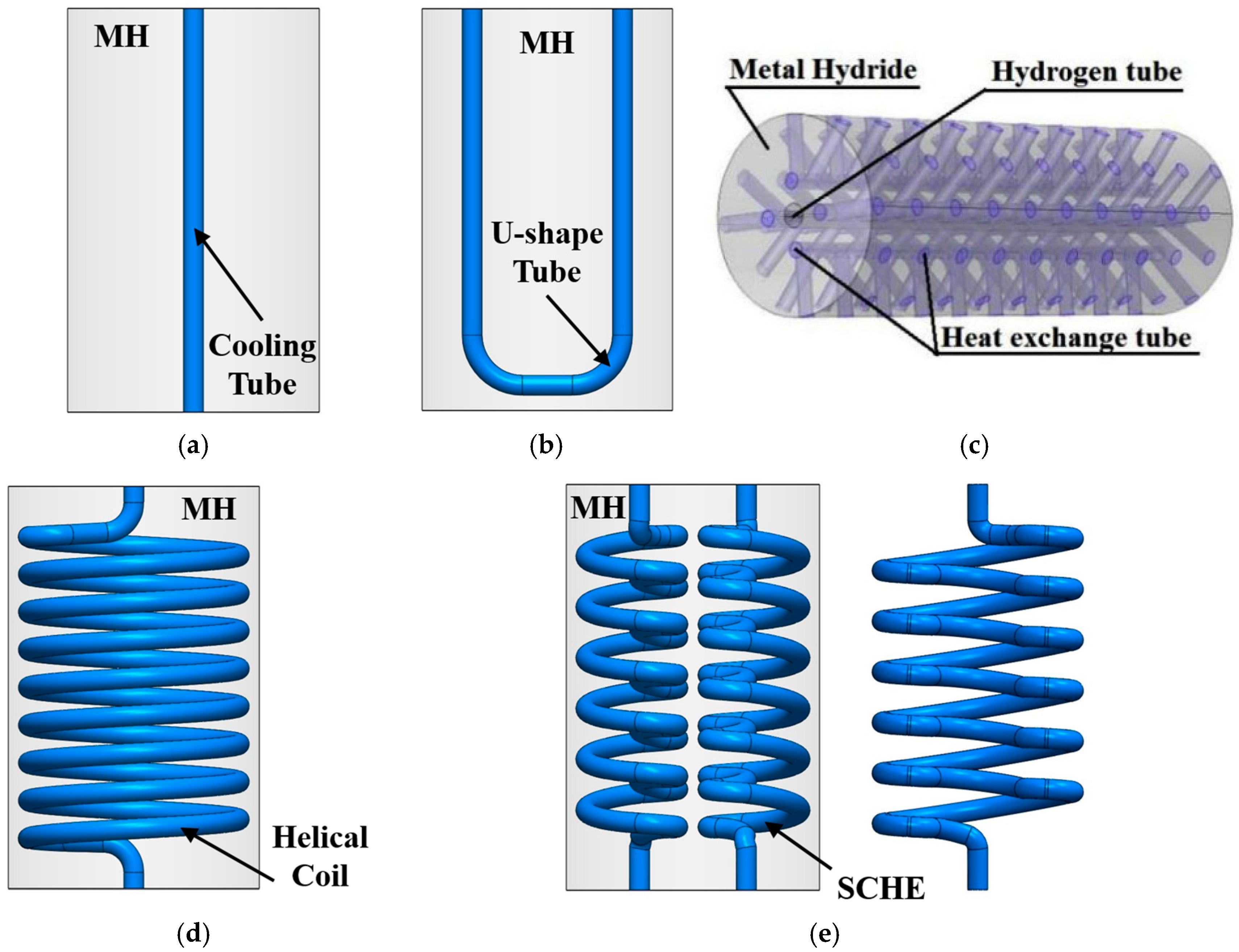
3.1.2. Internal Heat Exchanger
- Cooling tube
- U-shaped tube
- Mini-channel tubes
- Spiral/helical coil tube
- Semi-cylindrical coil tube
3.2. Design Optimisation for Passive Thermal Management Method
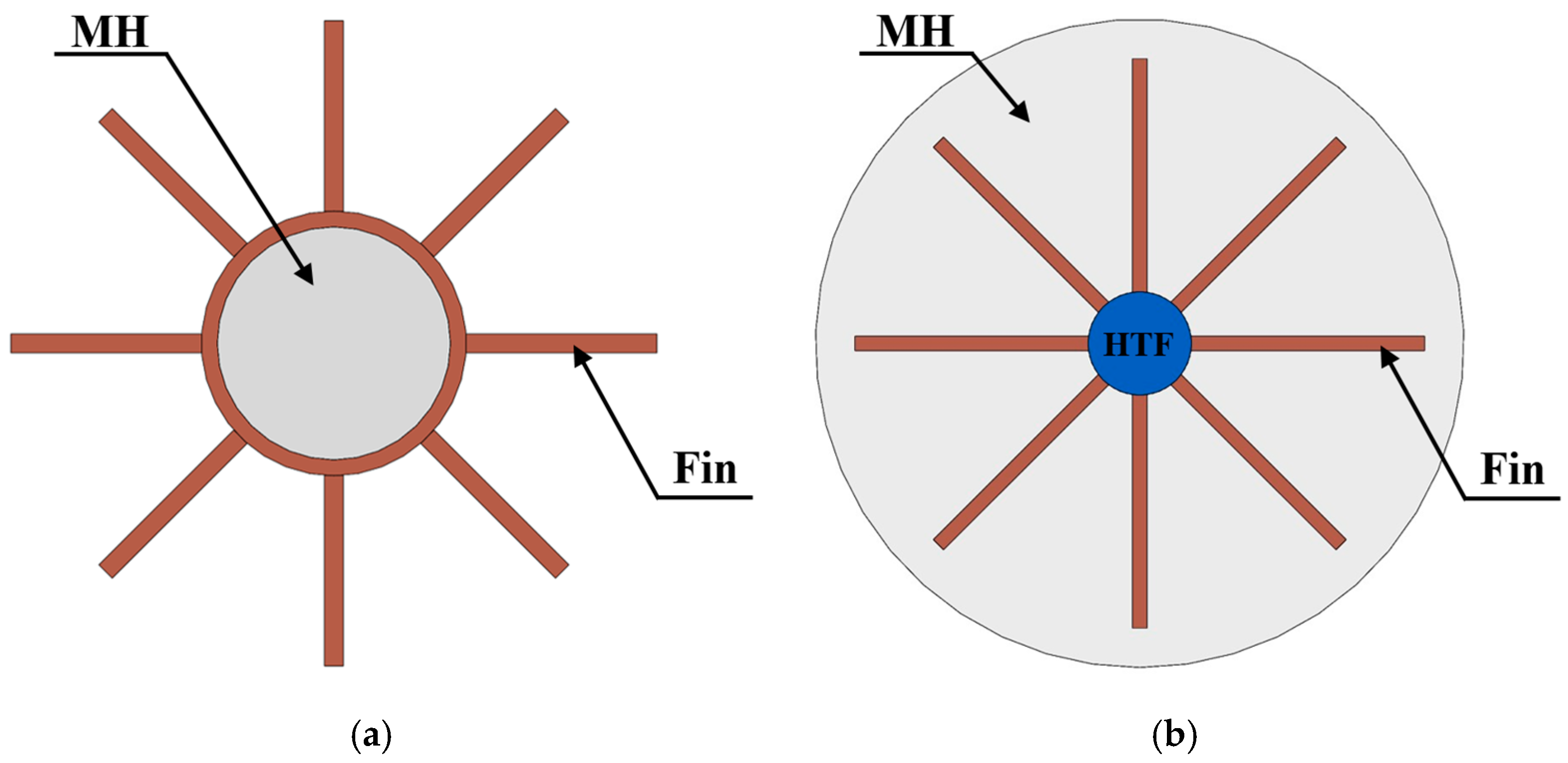
3.2.1. Fins
- External fins
- Internal fins
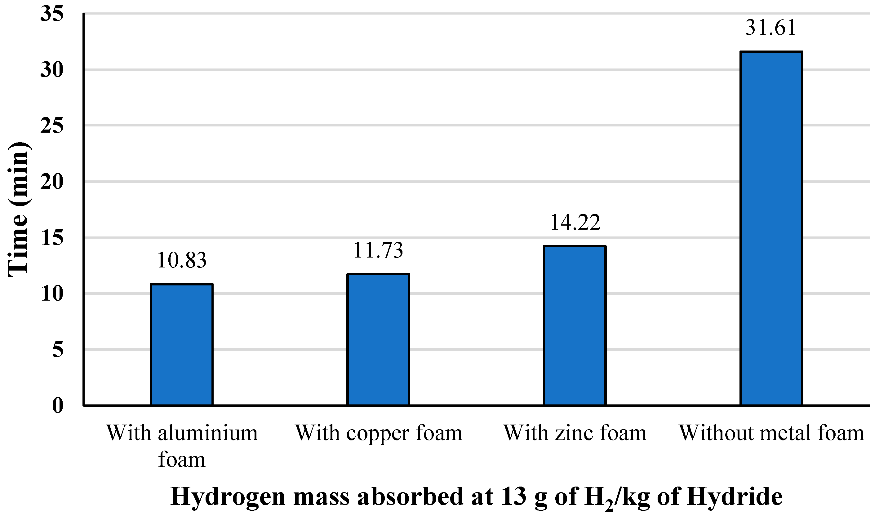
3.2.2. Metal Foam
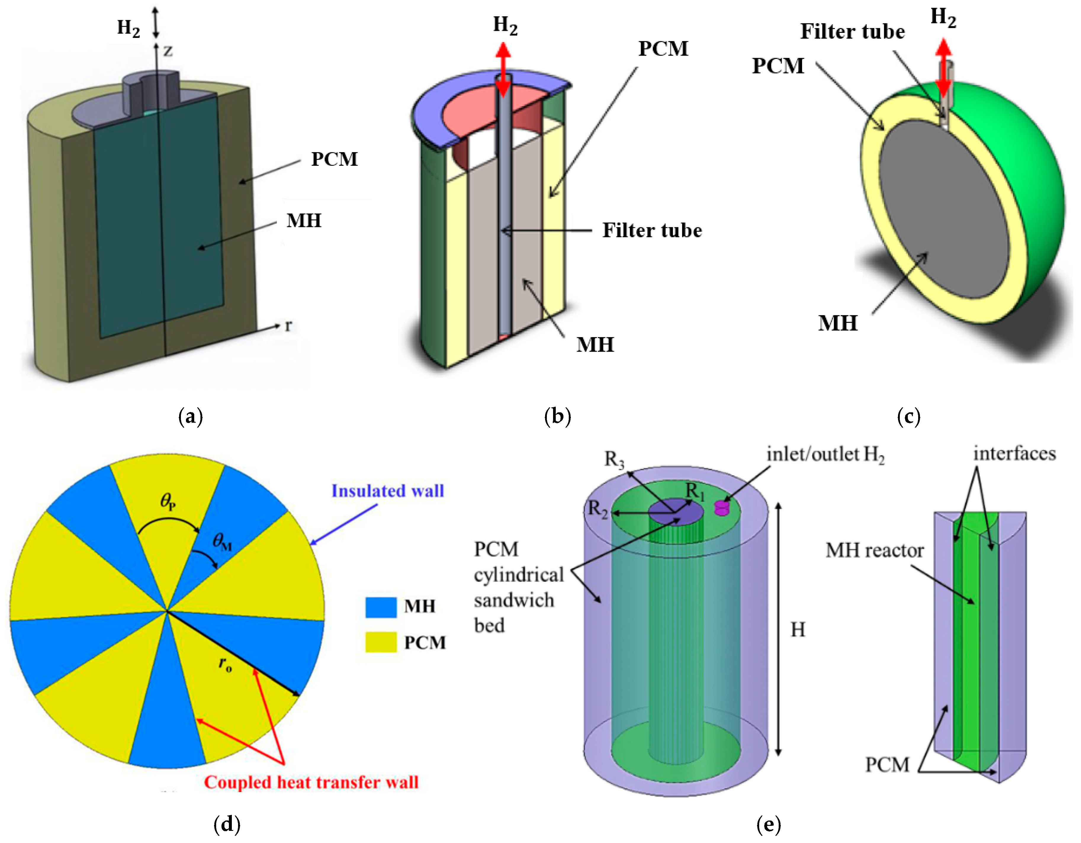
3.2.3. Phase Change Materials
- Pool bed
- Jacket bed
- Spherical bed
- Partition arrangement
- Sandwich bed
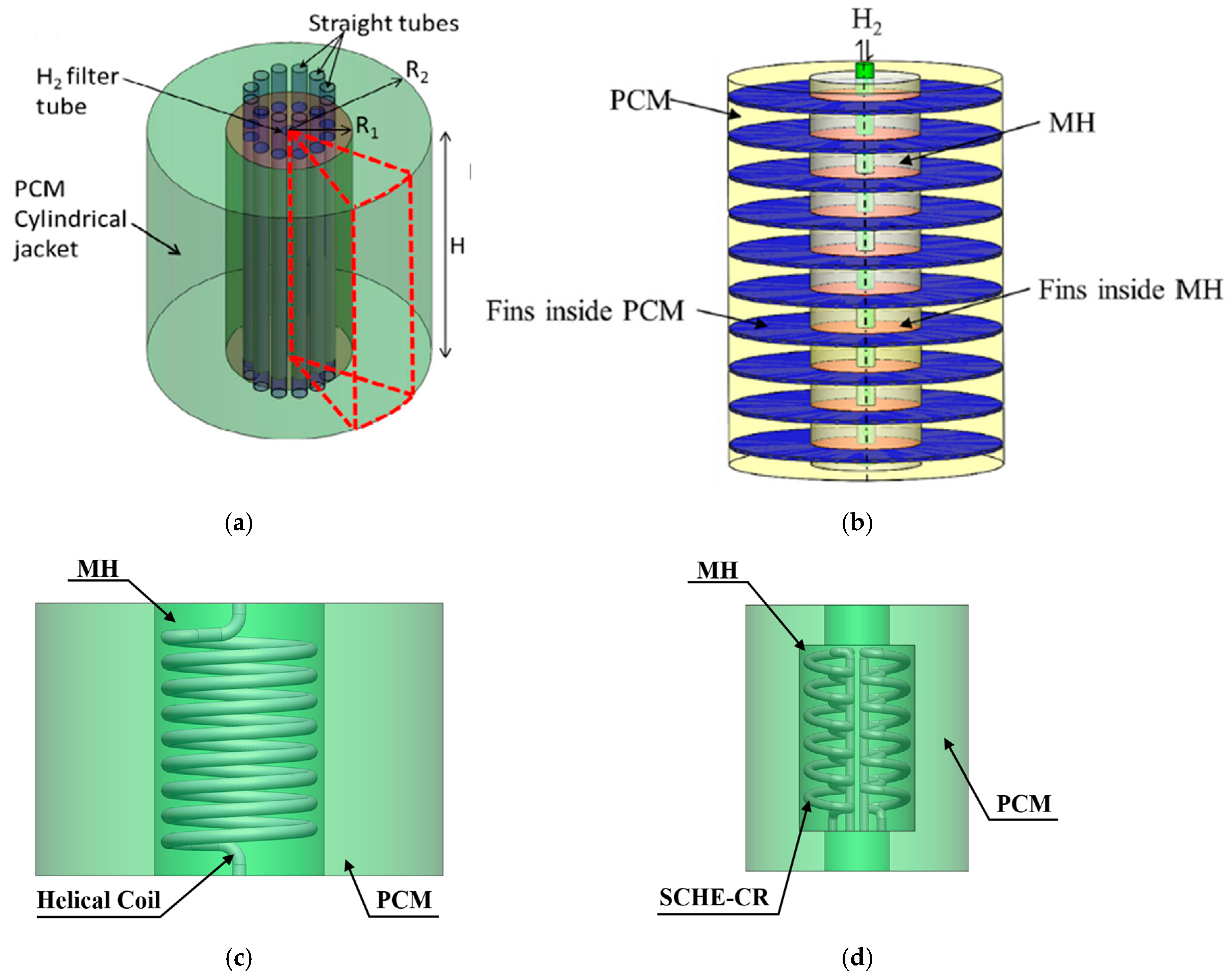
3.3. Design Optimisation Based on the Combination of Various Heat Exchanger Methods
- Active and passive thermal management methods
- Active and active thermal management methods
3.4. Comparison Between Various Heat Exchanger Methods and Performance
3.5. Heat Transfer Fluids
4. Operating Conditions
4.1. Initial Condition of the Metal Hydride Storage
4.2. Initial Condition of the Heat Transfer Fluid
4.3. Other Operating Conditions and Comparison of the Operating Parameters
5. Application Requirements and Economic Assessments for Metal Hydride Hydrogen Storage
6. Conclusions
- Metal hydride materials
- -
- Mg-based alloys such as Mg2Ni have high hydrogen storage capacity, light weight, and low cost, but they have low effective thermal conductivity. Intermetallic compounds such as La-based and Ti-based alloys have high effective thermal conductivity, but they have low hydrogen storage capacity.
- -
- The volumetric and gravimetric density, effective thermal conductivity, and cost of MH materials should be optimised to meet the overall requirements of mobile/stationary storage applications.
- Heat exchanger configurations
- -
- The well arrangement/layout of the heat exchanger structure is the key factor to increase heat transfer distribution inside the storage system. However, some limitations for manufacturing are likely in reality as most studies are based on numerical simulations.
- -
- The complex HTF tube structure obtains superior heat transfer performance compared to other heat exchangers. The complex HTF tube structure should be well designed and optimised to prevent huge pressure loss from the tube inlet throughout the tube outlet and maintain the system’s efficiency.
- -
- The heat exchangers’ characteristics are important for heat transfer enhancement. The coil pitch and diameter/radius are the key parameters for helical coil performance, while the number of fins and fin diameter/thickness are the main parameters for fin performance.
- -
- Appropriate design and optimisation of the MHHS configuration is the key factor when combining the MHHS with various heat exchanger types. The design and optimisation should be based on the gravimetric and volumetric parameters of the MHHS for each specific application.
- -
- When considering the gravimetric and volumetric parameters of the MHHS for mobile/stationary applications, passive heat exchanger types such as fins or PCM should be integrated with the HTF tube to improve the heat and mass transfer as well as reduce the overall storage weight.
- -
- When combining the PCM with other heat exchanger types, the proportional PCM/MH/HTF tube volume should be prioritised for improvement in hydrogen reaction kinetics.
- Operating conditions
- -
- The hydrogen supply pressure and the HTF temperature are the main parameters for improvement in hydrogen absorption/desorption reaction compared to other parameters. To avoid the reduction in total mass absorbed, appropriate selection of supply pressure should be prioritised and well studied for each new MHHSS configuration/application.
- -
- The HTC between the MH and HTF has a minor effect on the hydrogen sorption reaction for most MHHS types. The suitable value of the heat transfer coefficient is 500 W/mK with the use of La- and Mg-based alloys for both internal and external heat exchangers.
- -
- Changing the supply pressure significantly improves specific heating power by 40%, while other parameters result in less than a 30% improvement in specific heating power.
7. Limitation and Recommendation for Further Work
Funding
Conflicts of Interest
Abbreviations
| Abbreviations | |
| CFD | Computational fluid dynamics |
| ETC | Effective thermal conductivity |
| HSC | Hydrogen storage capacity |
| HTC | Heat transfer coefficient |
| HTF | Heat transfer fluid |
| MH | Metal hydride |
| MHHS | Metal hydride-based hydrogen storage |
| ML | Machine learning |
| PCM | Phase change material |
| Nomenclature | |
| Absorption rate constant, s−1 | |
| Desorption rate constant, s−1 | |
| Hydrogen reaction kinetics | |
| Activation energy for absorption, J mol−1 | |
| Activation energy for desorption, J mol−1 | |
| Equilibrium pressure, Pa | |
| Hydrogen pressure, Pa | |
| Reference pressure, Pa | |
| R | Universal gas constant, J K−1 mol−1 |
| Re | Reynolds number |
| T | Temperature, K |
| t | time, s |
| X | Absorbed hydrogen amount, wt% |
| Enthalpy of reaction, J mol−1 | |
| Entropy of reaction, J mol−1 K−1 | |
References
- Tange, M.; Maeda, T.; Nakano, A.; Ito, H.; Kawakami, Y.; Masuda, M.; Takahashi, T. Experimental study of hydrogen storage with reaction heat recovery using metal hydride in a totalised hydrogen energy utilisation system. Int. J. Hydrogen Energy 2011, 36, 11767–11776. [Google Scholar] [CrossRef]
- Yue, M.; Lambert, H.; Pahon, E.; Roche, R.; Jemei, S.; Hissel, D. Hydrogen energy system: A critical review of technologies, applications, trends and challenges. Renew. Sustain. Energy Rev. 2021, 146, 111180. [Google Scholar] [CrossRef]
- Hassanpouryouzband, A.; Wilkinson, M.; Haszeldine, R.S. Hydrogen energy futures foraging or farming? Chemical Society Reviews. R. Soc. Chem. 2024, 53, 2258–2263. [Google Scholar] [CrossRef] [PubMed]
- Hassanpouryouzband, A.; Veshareh, M.J.; Wilkinson, M.; Nick, H.M.; Ngwenya, B.T.; Haszeldine, R.S. In situ hydrogen generation from underground fossil hydrocarbons. Joule 2025, 9, 101809. [Google Scholar] [CrossRef]
- Dagdougui, H.; Sacile, R.; Bersani, C.; Ouammi, A. Hydrogen storage and distribution: Implementation scenarios. In Hydrogen Infrastructure for Energy Applications; Dagdougui, H., Sacile, R., Bersani, C., Ouammi, A., Eds.; Academic Press: Cambridge, UK, 2018; pp. 37–52. [Google Scholar]
- Colozza, A.J. Hydrogen Storage for Aircraft Applications Overview; Technical Report; Analex Corp: Brook Park, OH, USA, 2002. [Google Scholar]
- Moradi, R.; Groth, K.M. Hydrogen storage and delivery: Review of the state of the art technologies and risk and reliability analysis. Int. J. Hydrogen Energy 2019, 44, 12254–12269. [Google Scholar] [CrossRef]
- Marnellos, G.E.; Athanasiou, C.; Makridis, S.S.; Kikkinides, E.S. Integration of hydrogen energy technologies in autonomous power systems. In Hydrogen-Based Autonomous Power Systems: Techno-Economic Analysis of the Integration of Hydrogen in Autonomous Power Systems 2008; Springer: London, UK, 2004; pp. 23–81. [Google Scholar]
- Sakintuna, B.; Lamari-Darkrim, F.; Hirscher, M. Metal hydride materials for solid hydrogen storage: A review. Int. J. Hydrogen Energy 2007, 32, 1121–1140. [Google Scholar] [CrossRef]
- Jain, I.; Lal, C.; Jain, A. Hydrogen storage in Mg: A most promising material. Int. J. Hydrogen Energy 2010, 35, 5133–5144. [Google Scholar] [CrossRef]
- Rusman, N.; Dahari, M. A review on the current progress of metal hydrides material for solid-state hydrogen storage applications. Int. J. Hydrogen Energy 2016, 41, 12108–12126. [Google Scholar] [CrossRef]
- Chung, C.; Lin, C.S. Prediction of hydrogen desorption performance of Mg2Ni hydride reactors. Int. J. Hydrogen Energy 2009, 34, 9409–9423. [Google Scholar] [CrossRef]
- Wu, Z.; Yang, F.; Zhang, Z.; Bao, Z. Magnesium based metal hydride reactor incorporating helical coil heat exchanger: Simulation study and optimal design. Appl. Energy 2014, 130, 712–722. [Google Scholar] [CrossRef]
- Zhao, W.; Yang, Y.; Bao, Z.; Dong, Y.; Zhu, Z. Methods for measuring the effective thermal conductivity of metal hydride beds: A review. Int. J. Hydrogen Energy 2020, 45, 6680–6700. [Google Scholar] [CrossRef]
- Nguyen, H.Q.; Shabani, B. Review of metal hydride hydrogen storage thermal management for use in the fuel cell systems. Int. J. Hydrogen Energy 2021, 46, 31699–31726. [Google Scholar] [CrossRef]
- Muthukumar, P.; Kumar, A.; Raju, N.N.; Malleswararao, K.; Rahman, M.M. A critical review on design aspects and developmental status of metal hydride based thermal machines. Int. J. Hydrogen Energy 2018, 43, 17753–17779. [Google Scholar] [CrossRef]
- Rahnama, A.; Zepon, G.; Sridhar, S. Machine learning based prediction of metal hydrides for hydrogen storage, part I: Prediction of hydrogen weight percent. Int. J. Hydrogen Energy 2019, 44, 7337–7344. [Google Scholar] [CrossRef]
- Mocanu, E.; Nguyen, P.H.; Gibescu, M.; Kling, W.L. Deep learning for estimating building energy consumption. Sustain. Energy Grids Netw. 2016, 6, 91–99. [Google Scholar] [CrossRef]
- Hameed, G.; Ghafoor, M.A.; Yousaf, M.; Imran, M.; Zaman, M.; Elkamel, A.; Haq, A.; Rizwan, M.; Wilberforce, T.; Abdlkareem, M.A.; et al. Low temperature phase change materials for thermal energy storage: Current status and computational perspectives. Sustain. Energy Technol. Assess. 2022, 50, 101808. [Google Scholar] [CrossRef]
- Hirscher, M.; Yartys, V.A.; Baricco, M.; von Colbe, J.B.; Blanchard, D.; Bowman, R.C.; Broom, D.P.; Buckley, C.E.; Chang, F.; Chen, P.; et al. Materials for hydrogen-based energy storage—Past, recent progress and future outlook. J. Alloys Compd. 2020, 827, 153548. [Google Scholar] [CrossRef]
- Krishnayatra, G.; Tokas, S.; Kumar, R. Numerical heat transfer analysis & predicting thermal performance of fins for a novel heat exchanger using machine learning. Case Stud. Therm. Eng. 2020, 21, 100706. [Google Scholar]
- Kim, K.; Kang, M.; Lee, G.; Jung, K.; Kharangate, C.R.; Asheghi, M.; Goodson, K.E.; Lee, H. A machine learning approach for predicting heat transfer characteristics in micro-pin fin heat sinks. Int. J. Heat Mass Transf. 2022, 194, 123087. [Google Scholar] [CrossRef]
- Ostanek, J.K. Improving pin-fin heat transfer predictions using artificial neural networks. J. Turbomach. 2014, 136, 051010. [Google Scholar] [CrossRef]
- Balachandar, C.; Arunkumar, S.; Venkatesan, M. Computational heat transfer analysis and combined ANN–GA optimization of hollow cylindrical pin fin on a vertical base plate. Sadhana 2015, 40, 1845–1863. [Google Scholar] [CrossRef]
- Beigzadeh, R.; Rahimi, M.; Jafari, O.; Alsairafi, A.A. Computational fluid dynamics assists the artificial neural network and genetic algorithm approaches for thermal and flow modeling of air-forced convection on interrupted plate fins. Numer. Heat Transf. Part A Appl. 2016, 70, 546–565. [Google Scholar] [CrossRef]
- Lee, H.; Kang, M.; Jung, K.W.; Kharangate, C.R.; Lee, S.; Iyengar, M.; Malone, C.; Asheghi, M.; Goodson, K.E.; Lee, H. An artificial neural network model for predicting frictional pressure drop in micro-pin fin heat sink. Appl. Therm. Eng. 2021, 194, 117012. [Google Scholar] [CrossRef]
- Yu, X.; Shen, Y.; Guan, Z.; Zhang, D.; Tang, Z.; Li, W. Multi-objective optimization of ANN-based PSA model for hydrogen purification from steam-methane reforming gas. Int. J. Hydrogen Energy 2021, 46, 11740–11755. [Google Scholar] [CrossRef]
- Vo, N.D.; Kang, J.H.; Oh, D.H.; Jung, M.Y.; Chung, K.; Lee, C.H. Sensitivity analysis and artificial neural network-based optimization for low-carbon H2 production via a sorption enhanced steam methane reforming (SESMR) process integrated with separation process. Int. J. Hydrogen Energy 2021, 47, 820–847. [Google Scholar] [CrossRef]
- Jiang, Y.; Zhang, G.; Wang, J.; Vaferi, B. Hydrogen solubility in aromatic/cyclic compounds: Prediction by difference machine learning techniques. Int. J. Hydrogen Energy 2021, 46, 23591–23602. [Google Scholar] [CrossRef]
- Witman, M.; Ling, S.; Grant, D.M.; Walker, G.S.; Agarwal, S.; Stavila, V.; Allendorf, M.D. Extracting an empirical intermetallic hydride design principle from limited data via interpretable machine learning. J. Phys. Chem. Lett. 2020, 11, 40–47. [Google Scholar] [CrossRef]
- Sun, K.; Esnaola, I.; Okorie, O.; Charnley, F.; Moreno, M.; Tiwari, A. Data-driven modeling and monitoring of fuel cell performance. Int. J. Hydrogen Energy 2021, 46, 33206–33217. [Google Scholar] [CrossRef]
- Guarino, A.; Spagnuolo, G. Automatic features extraction of faults in PEM fuel cells by a Siamese artificial neural network. Int. J. Hydrogen Energy 2021, 46, 34854–34866. [Google Scholar] [CrossRef]
- Suwarno, S.; Dicky, G.; Suyuthi, A.; Effendi, M.; Witantyo, W.; Noerochim, L.; Ismail, M. Machine learning analysis of alloying element effects on hydrogen storage properties of AB2 metal hydrides. Int. J. Hydrogen Energy 2022, 47, 11938–11947. [Google Scholar] [CrossRef]
- Rahnama, A.; Zepon, G.; Sridhar, S. Machine learning based prediction of metal hydrides for hydrogen storage, part II: Prediction of material class. Int. J. Hydrogen Energy 2019, 44, 7345–7353. [Google Scholar] [CrossRef]
- Lundin, C.E.; Lynch, F.E.; Magee, C.B. A correlation between the interstitial hole sizes in intermetallic compounds and the thermodynamic properties of the hydrides formed from those compounds. J. Less Common Met. 1977, 56, 19–37. [Google Scholar] [CrossRef]
- Mendelsohn, M.H.; Gruen, D.M.; Dwight, A.E. The effect of aluminum additions on the structural and hydrogen absorption properties of AB5 alloys with particular reference to the LaNi5-xAlx ternary alloy system. J. Less Common Met. 1979, 63, 193–207. [Google Scholar] [CrossRef]
- Reilly, J.J.; Adzic, G.D.; Johnson, J.R.; Vogt, T.; Mukerjee, S.; McBreen, J. The correlation between composition and electrochemical properties of metal hydride electrodes. J. Alloys Compd. 1999, 293–295, 569–582. [Google Scholar] [CrossRef]
- DOE: US Department of Energy. Metal Hydride Storage Materials: Hydrogen and Fuel Cell Technologies Office. Available online: https://www.energy.gov/eere/fuelcells/metal-hydride-storage-materials (accessed on 5 January 2023).
- Aoyagi, H.; Aoki, K.; Masumoto, T. Effect of ball milling on hydrogen absorption properties of FeTi, Mg2Ni and LaNi5. J. Alloys Compd. 1995, 231, 804–809. [Google Scholar] [CrossRef]
- Corre, S.; Bououdina, M.; Fruchart, D.; Adachi, G.Y. Stabilisation of high dissociation pressure hydrides of formula La1−xCexNi5 with carbon monoxide. J. Alloys Compd. 1998, 275, 99–104. [Google Scholar] [CrossRef]
- Principi, G.; Agresti, F.; Maddalena, A.; Russo, S.L. The problem of solid state hydrogen storage. Energy 2009, 34, 2087–2091. [Google Scholar] [CrossRef]
- Hahne, E.; Kallweit, J. Thermal conductivity of metal hydride materials for storage of hydrogen: Experimental investigation. Int. J. Hydrogen Energy 1998, 23, 107–114. [Google Scholar] [CrossRef]
- Singh, A.K.; Singh, A.K.; Srivastava, O.N. On the synthesis of the Mg2Ni alloy by mechanical alloying. J. Alloys Compd. 1995, 227, 63–68. [Google Scholar] [CrossRef]
- Zaluski, L.; Zaluska, A.; Strom-Olsen, J.O. Hydrogen absorption in nanocrystalline Mg2Ni formed by mechanical alloying. J. Alloys Compd. 1995, 217, 245–249. [Google Scholar] [CrossRef]
- Abdellaoui, M.; Cracco, D.; Percheron-Guegan, A. Structural characterization and reversible hydrogen absorption properties of Mg2Ni rich nanocomposite materials synthesized by mechanical alloying. J. Alloys Compd. 1998, 268, 233–240. [Google Scholar] [CrossRef]
- Abdellaoui, M.; Mokbli, S.; Cuevas, F.; Latroche, M.; Guegan Percheron, A.; Zarrouk, H. Structural, solid-gas and electrochemical characterization of Mg2Ni-rich and MgxNi100-x amorphous-rich nanomaterials obtained by mechanical alloying. Int. J. Hydrogen Energy 2006, 31, 247–250. [Google Scholar] [CrossRef]
- Vija, R.; Sundaresan, R.; Maiya, M.P.; Murthy, S.S. Comparative evaluation of Mg-Ni hydrogen absorbing materials prepared by mechanical alloying. Int. J. Hydrogen Energy 2005, 30, 501–508. [Google Scholar] [CrossRef]
- Kojima, Y.; Kawai, Y.; Towata, S.I.; Matsunaga, T.; Shinozawa, T.; Kimbara, M. Development of metal hydride with high dissociation pressure. J. Alloys Compd. 2005, in press. [CrossRef]
- Aburto, A.; Orgaz, E. Ab initio structural and electronic investigation of magnetic R NiSn (R¼La, Ce, Pr, Nd) intermetallics and their hydrides. Phys. Rev. B 2007, 75, 045130. [Google Scholar] [CrossRef]
- Shao, H.; Liu, T.; Wang, Y.; Xu, H.; Li, X. Preparation of Mg-based hydrogen storage materials from metal nanoparticles. J. Alloys Compd. 2008, 465, 527–533. [Google Scholar] [CrossRef]
- Liang, G. Synthesis and hydrogen storage properties of Mg-based alloys. J. Alloys Compd. 2004, 370, 123–128. [Google Scholar] [CrossRef]
- Friedlmeier, G.; Groll, M. Proceedings International Symposium on Metal Hydrogen Systems, Les Diablerets, Switzerland, 25–30 August 1996; pp. 497–507.
- Pons, M.; Dantzer, P.; Guilleminot, J. A measurement technique and a new model for the wall heat transfer coefficient of a packed bed of (reactive) powder without gas flow. Int. J. Heat Mass Transf. 1993, 36, 2635–2646. [Google Scholar] [CrossRef]
- Pons, M.; Dantzer, P. Determination of thermal conductivity and wall heat transfer coefficient of hydrogen storage materials. Int. J. Hydrogen Energy 1994, 19, 611–616. [Google Scholar] [CrossRef]
- Ron, M.; Bershadsky, E.; Josephy, Y. The thermal conductivity of porous metal matrix hydride compacts. J. Less Common Met. 1991, 172, 1138–1146. [Google Scholar] [CrossRef]
- Ishido, Y.; Kawamura, M.; Ono, S. Thermal conductivity of magnesium-nickel hydride powder beds in a hydrogen atmosphere. Int. J. Hydrogen Energy 1982, 7, 173–182. [Google Scholar] [CrossRef]
- Suissa, E.; Jacob, I.; Hadari, Z. Experimental measurements and general conclusions on the effective thermal conductivity of powdered metal hydrides. J. Less Common Met. 1984, 104, 287–295. [Google Scholar] [CrossRef]
- Sun, D.W.; Deng, S.J. Theoretical descriptions and experimental measurements on the effective thermal conductivity in metal hydride powder beds. J. Less Common Met. 1990, 160, 387–395. [Google Scholar]
- Kumar, E.A.; Maiya, M.P.; Murthy, S.S. Measurement and analysis of effective thermal conductivity of MmNi4.5Al0.5 hydride bed. Ind. Eng. Chem. Res. 2011, 50, 12990–12999. [Google Scholar] [CrossRef]
- Christopher, M.D. Application of the Transient Hot-Wire Technique for Measurement of Effective Thermal Conductivity of Catalyzed Sodium Alanate for Hydrogen Storage; Virginia Tech: Blacksburg, VA, USA, 2006. [Google Scholar]
- Dedrick, D.; Kanouff, M.; Replogle, B.; Gross, K. Thermal properties characterization of sodium alanates. J. Alloys Compd. 2005, 389, 299–305. [Google Scholar] [CrossRef]
- Ahluwalia, R.K. Sodium alanate hydrogen storage system for automotive fuel cells. Int. J. Hydrogen Energy 2007, 32, 1251–1261. [Google Scholar] [CrossRef]
- Flueckiger, S.; Voskuilen, T.; Pourpoint, T.; Fisher, T.S.; Zheng, Y. In situ characterization of metal hydride thermal transport properties. Int. J. Hydrogen Energy 2010, 35, 614–621. [Google Scholar] [CrossRef]
- Goodell, P. Thermal conductivity of hydriding alloy powders and comparisons of reactor systems. J. Less Common Met. 1980, 74, 175–184. [Google Scholar] [CrossRef]
- Kempf, A.; Martin, W. Measurement of the thermal properties of TiFe0. 85Mn0. 15 and its hydrides. Int. J. Hydrogen Energy 1986, 11, 107–116. [Google Scholar] [CrossRef]
- Suda, S.; Kobayashi, N.; Yoshida, K.; Ishido, Y.; Ono, S. Experimental measurements of thermal conductivity. J. Less Common Met. 1980, 74, 127–136. [Google Scholar] [CrossRef]
- Suda, S.; Kobayashi, N.; Yoshida, K. Thermal conductivity in metal hydride beds. Int. J. Hydrogen Energy 1981, 6, 521–528. [Google Scholar] [CrossRef]
- Sandrock, G. A panoramic overview of hydrogen storage alloys from a gas reaction point of view. J. Alloys Compd. 1999, 293–295, 877–888. [Google Scholar] [CrossRef]
- Sandrock, G.D. Development of low cost nickel-rare earth hydrides for hydrogen storage. In Proceedings of the 2nd World Hydrogen Energy Conference, Zurich, Switzerland, 21–24 August 1978; Veziroglu, T.N., Seifritz, W., Eds.; Pergamon: Oxford, UK, 1979; Volume 3, pp. 1625–1656. [Google Scholar]
- Chandra, D.; Chien, W.M.; Talekar, A. Rare earths—Crucial elements of advanced technology. Mater. Matters 2011, 6, 51. [Google Scholar]
- Sandrock, G.; Thomas, G. Compilation of IEA/DOE/SNL Databases Technical Report for International Energy Agency (IEA); 1997. [Google Scholar]
- Reilly, J.; Wiswall, R.H. Hydrogen Storage and Purification Technical Report for Brookhaven National Laboratory. 1972. Available online: https://www.osti.gov/biblio/5291031 (accessed on 3 March 2025).
- Sreeraj, R.; Aadhithiyan, A.K.; Anbarasu, S. Integration of thermal augmentation methods in hydride beds for metal hydride based hydrogen storage systems: Review and recommendation. J. Energy Storage 2022, 52, 105039. [Google Scholar] [CrossRef]
- Mazzucco, A.; Dornheim, M.; Sloth, M.; Jensen, T.R.; Jensen, J.O.; Rokni, M. Bed geometries, fueling strategies and optimisation of heat exchanger designs in metal hydride storage systems for automotive applications: A review. Int. J. Hydrogen Energy 2014, 39, 17054–17074. [Google Scholar] [CrossRef]
- Chung, C.A.; Ho, C.J. Thermal-fluid behavior of the hydriding and dehydriding processes in a metal hydride hydrogen storage canister. Int. J. Hydrogen Energy 2009, 34, 4351–4364. [Google Scholar] [CrossRef]
- Valizadeh, M.; Aghajani Delavar, M.; Farhadi, M. Numerical simulation of heat and mass transfer during hydrogen desorption in metal hydride storage tank by Lattice Boltzmann method. Int. J. Hydrogen Energy 2016, 41, 413–424. [Google Scholar] [CrossRef]
- Wang, Y.; Adroher, X.C.; Chen, J.; Yang, X.G.; Miller, T. Three dimensional modeling of hydrogen sorption in metal hydride hydrogen storage beds. J. Power Sources 2009, 194, 997–1006. [Google Scholar] [CrossRef]
- Nam, J.; Ko, J.; Ju, H. Three-dimensional modeling and simulation of hydrogen absorption in metal hydride hydrogen storage vessels. Appl. Energy 2012, 89, 164–175. [Google Scholar] [CrossRef]
- Yoo, H.; Kim, W.; Ju, H. A numerical comparison of hydrogen absorption behaviors of uranium and zirconium cobaltbased metal hydride beds. Solid State Ioncs. 2014, 262, 241–247. [Google Scholar] [CrossRef]
- Patil, S.D.; Gopal, M.R. Analysis of a metal hydride reactor for hydrogen storage. Int. J. Hydrogen Energy 2013, 38, 942–951. [Google Scholar] [CrossRef]
- Urunkar, R.U.; Patil, S.D. Enhancement of heat and mass transfer characteristics of metal hydride reactor for hydrogen storage using various nanofluids. Int. J. Hydrogen Energy 2021, 46, 19486–19497. [Google Scholar] [CrossRef]
- Yiotis, A.G.; Kainourgiakis, M.E.; Charalambopoulou, G.C.; Stubos, A.K. A generic physical model for a thermally integrated high-temperature PEM fuel cell and sodium alanate tank system. Int. J. Hydrogen Energy 2015, 40, 14551–14561. [Google Scholar] [CrossRef]
- Hwang, J.J.; Chang, W.R. Characteristic study on fuel cell/ battery hybrid power system on a light electric vehicle. J. Power Sources 2012, 207, 111–119. [Google Scholar] [CrossRef]
- Weiss-Ungethum, J.; Burger, I.; Schmidt, N.; Linder, M.; Kallo, J. Experimental investigation of a liquid cooled high temperature proton exchange membrane (HT-PEM) fuel cell coupled to a sodium alanate tank. Int. J. Hydrogen Energy 2014, 39, 5931–5941. [Google Scholar] [CrossRef]
- Wu, Z.; Yang, F.; Zhu, L.; Feng, P.; Zhang, Z.; Wang, Y. Improvement in hydrogen desorption performances of magnesium based metal hydride reactor by incorporating helical coil heat exchanger. Int. J. Hydrogen Energy 2016, 41, 16108–16121. [Google Scholar] [CrossRef]
- Wang, D.; Wang, Y.; Huang, Z.; Yang, F.; Wu, Z.; Zheng, L. Design optimisation and sensitivity analysis of the radiation minichannel metal hydride reactor. Energy 2019, 173, 443–456. [Google Scholar] [CrossRef]
- Anbarasu, S.; Muthukumar, P.; Mishra, S.C. Thermal modeling of LmNi4.91Sn0.15 based solid state hydrogen storage device with embedded cooling tubes. Int. J. Hydrogen Energy 2014, 39, 15549–15562. [Google Scholar] [CrossRef]
- Bao, Z.; Wu, Z.; Nyamsi, S.N.; Yang, F.; Zhang, Z. Three-dimensional modeling and sensitivity analysis of multitubular metal hydride reactors. Appl. Therm. Eng. 2013, 52, 97–108. [Google Scholar] [CrossRef]
- Mellouli, S.; Dhaou, H.; Askri, F.; Jemni, A.; Nasrallah, S.B. Hydrogen storage in metal hydride tanks equipped with metal foam heat exchanger. Int. J. Hydrogen Energy 2009, 34, 9393–9401. [Google Scholar] [CrossRef]
- Raju, M.; Kumar, S. System simulation modeling and heat transfer in sodium alanate based hydrogen storage systems. Int. J. Hydrogen Energy 2011, 36, 1578–1591. [Google Scholar] [CrossRef]
- Hardy, B.J.; Anton, D.L. Hierarchical methodology for modelling hydrogen storage systems. Part II: Detailed models. Int. J. Hydrogen Energy 2009, 34, 2992–3004. [Google Scholar] [CrossRef]
- Bhouri, M.; Burger, I.; Linder, M. Numerical investigation of hydrogen charging performance for a combination reactor with embedded metal hydride and coolant tubes. Int. J. Hydrogen Energy 2015, 40, 6626–6638. [Google Scholar] [CrossRef]
- Mohan, G.; Maiya, M.P.; Murthy, S.S. Performance simulation of metal hydride hydrogen storage device with embedded filters and heat exchanger tubes. Int. J. Hydrogen Energy 2007, 32, 4978–4987. [Google Scholar] [CrossRef]
- Kumar, A.; Raju, N.N.; Muthukumar, P.; Selvan, P.V. Experimental studies on industrial scale metal hydride based hydrogen storage system with embedded cooling tubes. Int. J. Hydrogen Energy 2019, 44, 13549–13560. [Google Scholar] [CrossRef]
- Raju, N.N.; Kumar, A.; Malleswararao, K.; Muthukumar, P. Parametric studies on LaNi4. 7Al0. 3 based hydrogen storage reactor with embedded cooling tubes. Energy Procedia 2019, 158, 2384–2390. [Google Scholar] [CrossRef]
- Singh, A.; Maiya, M.P.; Srinivasa Murthy, S. Performance of a solid state hydrogen storage device with finned tube heat exchanger. Int. J. Hydrogen Energy 2017, 42, 26855–26871. [Google Scholar] [CrossRef]
- Singh, A.; Maiya, M.P.; Srinivasa Murthy, S. Experiments on solid state hydrogen storage device with a finned tube heat exchanger. Int. J. Hydrogen Energy 2017, 42, 15226–15235. [Google Scholar] [CrossRef]
- Singh, A.; Maiya, M.P.; Srinivasa Murthy, S. Effects of heat exchanger design on the performance of a solid state hydrogen storage device. Int. J. Hydrogen Energy 2015, 40, 9733–9746. [Google Scholar] [CrossRef]
- Yang, W.; Ye, Y.; Cheng, H.; Liu, J.; Yan, K.; Miao, H. Performance optimization of a U-tube heat exchanger type hydrogen storage reactor with a novel fin structure. Int. J. Hydrogen Energy 2025, 82, 272–280. [Google Scholar] [CrossRef]
- Li, H.; Wang, Y.; He, C.; Chen, X.; Zhang, Q.; Zheng, L.; Yang, F.; Zhang, Z. Design and performance simulation of the spiral mini-channel reactor during H2 absorption. Int. J. Hydrogen Energy 2015, 40, 13490–13505. [Google Scholar] [CrossRef]
- Meng, X.; Wu, Z.; Bao, Z.; Yang, F.; Zhang, Z. Performance simulation and experimental confirmation of a minichannel metal hydrides reactor. Int. J. Hydrogen Energy 2013, 38, 15242–15253. [Google Scholar] [CrossRef]
- Wang, D.; Wang, Y.; Wang, F.; Zheng, S.; Guan, S.; Zheng, L.; Wu, L.; Fang, T.; Yang, X.; Lv, M. Hydrogen storage in branch mini-channel metal hydride reactor: Optimisation design, sensitivity analysis and quadratic regression. Int. J. Hydrogen Energy 2021, 46, 25189–25207. [Google Scholar] [CrossRef]
- Fernández, R.Á.; Caraballo, C.S.; Cilleruelo, B.F.; Lozano, J.A. Fuel optimization strategy for hydrogen fuel cell range extender vehicles applying genetic algorithms. Renew. Sustain. Energy Rev. 2018, 81, 655–668. [Google Scholar] [CrossRef]
- Raju, M.; Kumar, S. Optimisation of heat exchanger designs in metal hydride based hydrogen storage systems. Int. J. Hydrogen Energy 2012, 37, 2767–2778. [Google Scholar] [CrossRef]
- Shafiee, S.; McCay, M.H. Different reactor and heat exchanger configurations for metal hydride hydrogen storage systemsea review. Int. J. Hydrogen Energy 2016, 41, 9462–9470. [Google Scholar] [CrossRef]
- Wang, H.; Prasad, A.K.; Advani, S.G. Hydrogen storage system based on hydride materials incorporating a helical-coil heat exchanger. Int. J. Hydrogen Energy 2012, 37, 14292–14299. [Google Scholar] [CrossRef]
- Mellouli, S.; Askri, F.; Dhaou, H.; Jemni, A.; Nasrallah, S.B. A novel design of a heat exchanger for a metal-hydrogen reactor. Int. J. Hydrogen Energy 2007, 32, 3501–3507. [Google Scholar] [CrossRef]
- Bhogilla, S.S. Design of a AB2-metal hydride cylindrical tank for renewable energy storage. J. Energy Storage 2017, 14, 203–210. [Google Scholar] [CrossRef]
- Visaria, M.; Mudawar, I. Coiled-tube heat exchanger for high pressure Metal Hydride hydrogen storage systemse Part 1. Experimental study. Int. J. Heat Mass Transf. 2012, 55, 1782–1795. [Google Scholar] [CrossRef]
- Visaria, M.; Mudawar, I. Coiled-tube heat exchanger for high pressure metal hydride hydrogen storage systemse Part 2. Computational model. Int. J. Heat Mass Transf. 2012, 55, 1796–1806. [Google Scholar] [CrossRef]
- Dong, D.; Humphries, T.D.; Sheppard, D.A.; Stansby, B.; Paskevicius, M.; Sofianos, M.V.; Chaudhary, A.L.; Dornheim, M.; Buckley, C.E. Thermal optimisation of metal hydride reactors for thermal energy storage applications. Sustain. Energy Fuels 2017, 1, 1820. [Google Scholar] [CrossRef]
- Mathew, A.; Nadim, N.; Chandratilleke, T.T.; Humphries, T.D.; Paskevicius, M.; Buckley, C.E. Performance analysis of a hightemperature magnesium hydride reactor tank with a helical coil heat exchanger for thermal storage. Int. J. Hydrogen Energy 2021, 46, 1038–1055. [Google Scholar] [CrossRef]
- Tiwari, S.; Sharma, P. Optimisation based methodology to design metal hydride reactor for thermal storage application. J. Energy Storage 2021, 41, 102845. [Google Scholar] [CrossRef]
- Ardahaie, S.S.; Hosseini, M.J.; Eisapour, M.; Eisapour, A.H.; Ranjbar, A.A. A novel porous metal hydride tank for hydrogen energy storage and consumption assisted by PCM jackets and spiral tubes. J. Clean. Prod. 2021, 311, 127674. [Google Scholar] [CrossRef]
- Eisapour, A.H.; Naghizadeh, A.; Eisapour, M.; Talebizadehsardari, P. Optimal design of a metal hydride hydrogen storage bed using a helical coil heat exchanger along with a central return tube during the absorption process. Int. J. Hydrogen Energy 2021, 46, 14478–14493. [Google Scholar] [CrossRef]
- Wang, D.; Li, S.; Huang, Z.; Liu, Z.; Wang, Y.; Yang, F.; Wu, Z.; Zhang, Z.; Wu, J.; Shi, L.; et al. Design optimisation, sensitivity analysis and operational comparison of a duplex helical elliptical tube metal hydride reactor. Sustain. Energy Fuels 2020, 4, 5851–5868. [Google Scholar] [CrossRef]
- Larpruenrudee, P.; Bennett, N.S.; Gu, Y.T.; Fitch, R.; Islam, M.S. Design optimization of a magnesium-based metal hydride hydrogen energy storage system. Sci. Rep. 2022, 12, 13436. [Google Scholar] [CrossRef]
- Larpruenrudee, P.; Bennett, N.S.; Hossain, M.J.; Fitch, R.; Islam, M.S. Hydrogen energy storage system: How does the semi-cylindrical helical coil heat exchanger affect metal hydride beds’ thermal conductivity? In Proceeding of the 23rd Australasian Fluid Mechanics Conference, Sydney, Australia, 4–8 December 2022; p. 421. [Google Scholar]
- Larpruenrudee, P.; Bennett, N.S.; Luo, Z.; Fitch, R.; Sauret, E.; Islam, M.S. A novel design for faster hydrogen storage: A combined semi-cylindrical and central return tube heat exchanger. J. Energy Storage 2023, 71, 108018. [Google Scholar] [CrossRef]
- Larpruenrudee, P.; Bennett, N.S.; Fitch, R.; Sauret, E.; Gu, Y.T.; Islam, M.S. Investigation of metal hydride hydrogen storage performance using phase change materials. Int. J. Hydrogen Energy 2024, 60, 996–1019. [Google Scholar] [CrossRef]
- Andreasen, G.; Melnichuk, M.; Ramos, S.; Corso, H.L.; Visintin, A.; Triaca, W.E.; Peretti, H.A. Hydrogen desorption from a hydride container under different heat exchange conditions. Int. J. Hydrogen Energy 2013, 38, 13352–13359. [Google Scholar] [CrossRef]
- MacDonald, B.D.; Rowe, A.M. Impacts of external heat transfer enhancements on metal hydride storage tanks. Int. J. Hydrogen Energy 2006, 31, 1721–1731. [Google Scholar] [CrossRef]
- Veerraju, C.; Gopal, M.R. Heat and mass transfer studies on plate fin-and-elliptical tube type metal hydride reactors. Appl. Therm. Eng. 2010, 30, 673–682. [Google Scholar] [CrossRef]
- Keshari, V.; Maiya, M.P. Design and investigation of hydriding alloy based hydrogen storage reactor integrated with a pin fin tube heat exchanger. Int. J. Hydrogen Energy 2018, 43, 7081–7095. [Google Scholar] [CrossRef]
- Nyamsi, S.N.; Yang, F.; Zhang, Z. An optimisation study on the finned tube heat exchanger used in hydride hydrogen storage systemeanalytical method and numerical simulation. Int. J. Hydrogen Energy 2012, 37, 16078–16092. [Google Scholar] [CrossRef]
- Keshari, V.; Maiya, M.P. Numerical study of solid state hydrogen storage system with finned tube heat exchanger. Heat Transf. Eng. 2020, 41, 484–496. [Google Scholar] [CrossRef]
- Garrison, S.L.; Hardy, B.J.; Gorbounov, M.B.; Tamburello, D.A.; Corgnale, C.; Mosher, D.A.; Anton, D.L. Optimisation of internal heat exchangers for hydrogen storage tanks utilising metal hydrides. Int. J. Hydrogen Energy 2012, 37, 2850–2861. [Google Scholar] [CrossRef]
- Muthukumar, P.; Singhal, A.; Bansal, G. Thermal modeling and performance analysis of industrial-scale metal hydride based hydrogen storage container. Int. J. Hydrogen Energy 2012, 37, 14351–14364. [Google Scholar] [CrossRef]
- Krishna, K.V.; Kanti, P.K.; Maiya, M.P. A novel fin efficiency concept to optimize solid state hydrogen storage reactor. Energy 2024, 288, 129789. [Google Scholar] [CrossRef]
- Mellouli, S.; Abhilash, E.; Askri, F.; Nasrallah, S.B. Integration of thermal energy storage unit in a metal hydride hydrogen storage tank. Appl. Therm. Eng. 2016, 102, 1185–1196. [Google Scholar] [CrossRef]
- Alqahtani, T.; Mellouli, S.; Bamasag, A.; Askri, F.; Phelan, P.E. Thermal performance analysis of a metal hydride reactor encircled by a phase change material sandwich bed. Int. J. Hydrogen Energy 2020, 45, 23076–23092. [Google Scholar] [CrossRef]
- Alqahtani, T.; Mellouli, S.; Bamasag, A.; Askri, F.; Phelan, P.E. Cyclic behaviors of a novel design of a metal hydride reactor encircled by cascaded phase change materials. Int. J. Hydrogen Energy 2020, 45, 32285–32297. [Google Scholar] [CrossRef]
- Afzal, M.; Sharma, P. Design of a large-scale metal hydride based hydrogen storage reactor: Simulation and heat transfer optimisation. Int. J. Hydrogen Energy 2018, 43, 13356–13372. [Google Scholar] [CrossRef]
- Minko, K.B.; Artemov, V.I.; Yan’Kov, G.G. Numerical study of hydrogen purification using metal hydride reactor with aluminium foam. Appl. Therm. Eng. 2015, 76, 175–184. [Google Scholar] [CrossRef]
- Suda, S. Recent development of hydride energy systems in Japan. Int. J. Hydrogen Energy 1985, 10, 757–765. [Google Scholar] [CrossRef]
- Laurencelle, F.; Goyette, J. Simulation of heat transfer in a metal hydride reactor with aluminium foam. Int. J. Hydrogen Energy 2007, 32, 2957–2964. [Google Scholar] [CrossRef]
- Ferekh, S.; Gwak, G.; Kyoung, S.; Kang, H.; Chang, M.; Yun, S.; Oh, Y.-H.; Kim, W.; Kim, D.; Hong, T.; et al. Numerical comparison of heat-fin-and-metal-foam-based hydrogen storage beds during hydrogen charging process. Int. J. Hydrogen Energy 2015, 40, 1440–1450. [Google Scholar] [CrossRef]
- Darzi, A.A.R.; Afrouzi, H.H.; Moshfegh, A.; Farhadi, M. Absorption and desorption of hydrogen in long metal hydride tank equipped with phase change material jacket. Int. J. Hydrogen Energy 2016, 41, 9595–9610. [Google Scholar] [CrossRef]
- Kalbasi, R. Introducing a novel heat sink comprising PCM and air-adapted to electronic device thermal management. Int. J. Heat Mass Transf. 2021, 169, 120914. [Google Scholar] [CrossRef]
- Ren, Q.; Guo, P.; Zhu, J. Thermal management of electronic devices using pin-fin based cascade microencapsulated PCM/expanded graphite composite. Int. J. Heat Mass Transf. 2020, 149, 119199. [Google Scholar] [CrossRef]
- Adilkhanova, I.; Memon, S.A.; Kim, J.; Sheriyev, A. A novel approach to investigate the thermal comfort of the lightweight relocatable building integrated with PCM in different climates of Kazakhstan during summertime. Energy 2021, 217, 119390. [Google Scholar] [CrossRef]
- Qu, Y.; Zhou, D.; Xue, F.; Cui, L. Multi-factor analysis on thermal comfort and energy saving potential for PCM-integrated buildings in summer. Energy Build. 2021, 241, 110966. [Google Scholar] [CrossRef]
- Ling, Z.; Zhang, Z.; Shi, G.; Fang, X.; Wang, L.; Gao, X.; Fang, Y.; Xu, T.; Wang, S.; Liu, X. Review on thermal management systems using phase change materials for electronic components, Li-ion batteries and photovoltaic modules. Renew. Sustain. Energy Rev. 2014, 31, 427–438. [Google Scholar] [CrossRef]
- Cui, Y.; Zeng, X.; Xiao, J.; Kou, H. The comprehensive review for development of heat exchanger configuration design in metal hydride bed. Int. J. Hydrogen Energy 2022, 47, 2461–2490. [Google Scholar] [CrossRef]
- Nyamsi, S.N.; Tolj, I.; Lotoskyy, M. Metal hydride beds-phase change materials, dual mode thermal energy storage for medium-high temperature industrial waste heat recovery. Energies 2019, 12, 3949. [Google Scholar] [CrossRef]
- Tong, L.; Xiao, J.; B´enard, P.; Chahine, R. Thermal management of metal hydride hydrogen storage reservoir using phase change materials. Int. J. Hydrogen Energy 2019, 44, 21055–21066. [Google Scholar] [CrossRef]
- Tong, L.; Yuan, Y.; Yang, T.; Benard, P.; Yuan, C.; Xiao, J. Hydrogen release from a metal hydride tank with phase change material jacket and coiled-tube heat exchanger. Int. J. Hydrogen Energy 2021, 46, 32135–32148. [Google Scholar] [CrossRef]
- Yao, J.; Zhu, P.; Guo, L.; Duan, L.; Zhang, Z.; Kurko, S.; Wu, Z. A continuous hydrogen absorption/desorption model for metal hydride reactor coupled with PCM as heat management and its application in the fuel cell power system. Int. J. Hydrogen Energy 2020, 45, 28087–28099. [Google Scholar] [CrossRef]
- El Mghari, H.; Huot, J.; Tong, L.; Xiao, J. Selection of phase change materials, metal foams and geometries for improving metal hydride performance. Int. J. Hydrogen Energy 2020, 45, 14922–14939. [Google Scholar] [CrossRef]
- El Mghari, H.; Huot, J.; Xiao, J. Analysis of hydrogen storage performance of metal hydride reactor with phase change materials. Int. J. Hydrogen Energy 2019, 44, 28893–28908. [Google Scholar] [CrossRef]
- Lewis, S.D.; Chippar, P. Analysis of heat and mass transfer during charging and discharging in a metal hydride-phase change material reactor. J. Energy Storage 2021, 33, 102108. [Google Scholar] [CrossRef]
- Maad, H.B.; Askri, F.; Nasrallah, S.B. Heat and mass transfer in a metal hydrogen reactor equipped with a phase-change heat-exchanger. Int. J. Therm. Sci. 2016, 99, 271–278. [Google Scholar] [CrossRef]
- Maad, H.B.; Miled, A.; Askri, F.; Nasrallah, S.B. Numerical simulation of absorption-desorption cyclic processes for metal-hydrogen reactor with heat recovery using phasechange material. Appl. Therm. Eng. 2016, 96, 267–276. [Google Scholar] [CrossRef]
- Garrier, S.; Delhomme, B.; De Rango, P.; Marty, P.; Fruchart, D.; Miraglia, S. A new MgH2 tank concept using a phase-change material to store the heat of reaction. Int. J. Hydrogen Energy 2013, 38, 9766–9771. [Google Scholar] [CrossRef]
- Mellouli, S.; Khedher, N.B.; Askri, F.; Jemni, A.; Nasrallah, S.B. Numerical analysis of metal hydride tank with phase change material. Appl. Therm. Eng. 2015, 90, 674–682. [Google Scholar] [CrossRef]
- Mellouli, S.; Askri, F.; Abhilash, E.; Nasrallah, S.B. Impact of using a heat transfer fluid pipe in a metal hydride-phase change material tank. Appl. Therm. Eng. 2017, 113, 554–565. [Google Scholar] [CrossRef]
- Nguyen, H.Q.; Shabani, B. Metal hydride thermal management using phase change material in the context of a standalone solar-hydrogen system. Energy Convers. Manag. 2020, 224, 113352. [Google Scholar] [CrossRef]
- Ye, Y.; Lu, J.; Ding, J.; Wang, W.; Yan, J. Numerical simulation on the storage performance of a phase change materials based metal hydride hydrogen storage tank. Appl. Energy 2020, 278, 115682. [Google Scholar] [CrossRef]
- Maad, H.B.; Askri, F.; Virgone, J.; Nasrallah, S.B. Numerical study of high temperature metal-hydrogen reactor (Mg2Ni-H2) with heat reaction recovery using phase change material during desorption. Appl. Therm. Eng. 2018, 140, 225–234. [Google Scholar] [CrossRef]
- Dai, H.; Chen, Z.; Cao, H.; Tian, Z.; Zhang, M.; Wang, X.; He, S.; Wang, W.; Gao, M. Effect of partition arrangement of metal hydrides and phase change materials on hydrogen absorption performance in the metal hydride reactor. Int. J. Hydrogen Energy 2024, 84, 780–792. [Google Scholar] [CrossRef]
- Ye, Y.; Ding, J.; Wang, W.; Yan, J. The storage performance of metal hydride storage tanks with reaction heat recovery by phase change materials. Appl. Energy 2021, 299, 117255. [Google Scholar] [CrossRef]
- Ye, Y.; Yue, Y.; Lu, J.; Ding, J.; Wang, W.; Yan, J. Enhanced hydrogen storage of a LaNi5 based reactor by using phase change materials. Renew. Energy 2021, 180, 734–743. [Google Scholar] [CrossRef]
- Bai, X.S.; Yang, W.W.; Tang, X.Y.; Yang, F.S.; Jiao, Y.H.; Yang, Y. Optimisation of tree-shaped fin structures towards enhanced absorption performance of metal hydride hydrogen storage device: A numerical study. Energy 2021, 220, 119738. [Google Scholar] [CrossRef]
- Souahlia, A.; Dhaou, H.; Mellouli, S.; Askri, F.; Jemni, A.; Nasrallah, S.B. Experimental study of metal hydride-based hydrogen storage tank at constant supply pressure. Int. J. Hydrogen Energy 2014, 39, 7365–7372. [Google Scholar] [CrossRef]
- Ma, J.; Wang, Y.; Shi, S.; Yang, F.; Bao, Z.; Zhang, Z. Optimisation of heat transfer device and analysis of heat & mass transfer on the finned multi-tubular metal hydride tank. Int. J. Hydrogen Energy 2014, 39, 13583–13595. [Google Scholar]
- Mallik, A.; Sharma, P. Modeling and numerical simulation of an industrial scale metal hydride reactor based on CFD-Taguchi combined method. Energy Storage 2021, 3, 227. [Google Scholar] [CrossRef]
- Liu, Y.; Wang, H.; Ayub, I.; Yang, F.; Wu, Z.; Zhang, Z. A variable cross-section annular fins type metal hydride reactor for improving the phenomenon of inhomogeneous reaction in the thermal energy storage processes. Appl. Energy 2021, 295, 117073. [Google Scholar] [CrossRef]
- Ayub, I.; Nasir, M.S.; Liu, Y.; Munir, A.; Wu, Z.; Yang, F.; Zhang, Z. Numerical modeling and performance comparison of high-temperature metal hydride reactor equipped with bakery system for solar thermal energy storage. Int. J. Hydrogen Energy 2020, 45, 31612–31631. [Google Scholar] [CrossRef]
- Krishna, K.B.; Kanti, P.K.; Maiya, M.P. Design optimization of metal hydride-based hydrogen storage reactor using fin efficiency concept. In Proceedings of the 38th ISTANBUL International Conference on Advances in “Science, Engineering & Technology” (IASET-24), Istanbul, Turkiye, 13–15 May 2024. [Google Scholar]
- Dhaou, H.; Ben Khedher, N.; Mellouli, S.; Souahlia, A.; Askri, F.; Jemni, A.; Ben Nasrallah, S. Improvement of thermal performance of spiral heat exchanger on hydrogen storage by adding copper fins. Int. J. Therm. Sci. 2011, 50, 2536–2542. [Google Scholar] [CrossRef]
- Mellouli, S.; Askri, F.; Dhaou, H.; Jemni, A.; Nasrallah, S.B. Numerical simulation of heat and mass transfer in metal hydride hydrogen storage tanks for fuel cell vehicles. Int. J. Hydrogen Energy 2010, 35, 1693–1705. [Google Scholar] [CrossRef]
- Krishna, K.V.; Kanti, P.K.; Maiya, M.P. A novel flat coil tube heat exchanger for metal hydride hydrogen storage reactors. Int. J. Hydrogen Energy 2024, 64, 98–108. [Google Scholar] [CrossRef]
- Freni, A.; Cipiti, F.; Cacciola, G. Finite element-based simulation of a metal hydride-based hydrogen storage tank. Int. J. Hydrogen Energy 2009, 34, 8574–8582. [Google Scholar] [CrossRef]
- Karmakar, A.; Mallik, A.; Gupta, N.; Sharma, P. Studies on 10kg alloy mass metal hydride based reactor for hydrogen storage. Int. J. Hydrogen Energy 2021, 46, 5495–5506. [Google Scholar] [CrossRef]
- Shtivastav, A.P.; Kanti, P.K.; Mohan, G.; Maiya, M.P. Design and optimization of metal hydride reactor with phase change material using fin factor for hydrogen storage. J. Energy Storage 2024, 77, 109975. [Google Scholar] [CrossRef]
- Kaplan, Y. Effect of design parameters on enhancement of hydrogen charging in metal hydride reactors. Int. J. Hydrogen Energy 2009, 34, 2288–2294. [Google Scholar] [CrossRef]
- Tong, L.; Xiao, J.; Yang, T.; B´enard, P.; Chahine, R. Complete and reduced models for metal hydride reactor with coiled-tube heat exchanger. Int. J. Hydrogen Energy 2019, 44, 15907–15916. [Google Scholar] [CrossRef]
- Askri, F.; Salah, M.B.; Jemni, A.; Nasrallah, S.B. Optimisation of hydrogen storage in metal-hydride tanks. Int. J. Hydrogen Energy 2009, 34, 897–905. [Google Scholar] [CrossRef]
- Sekhar, B.S.; Lototskyy, M.; Kolesnikov, A.; Moropeng, M.L.; Tarasov, B.; Pollet, B. Performance analysis of cylindrical metal hydride beds with various heat exchange options. J. Alloys Compd. 2015, 645, S89–S95. [Google Scholar] [CrossRef]
- Zheng, S.; Wang, Y.; Wang, D.; Guan, S.; Liu, Y.; Wang, F.; Zheng, L.; Wu, L.; Gao, X.; Zhang, Z. Design and performance study on the primary & secondary helical-tube reactor. Energy 2023, 263, 125840. [Google Scholar]
- Guan, F.; Ma, W.; Tu, Y.; Zhou, C.; Zhou, B. An experimental study of flow behavior of coiled tubing drilling system. Adv. Mech. Eng. 2014, 6, 935159. [Google Scholar] [CrossRef]
- Zhang, Z.; Liu, H. Research on the thermal performance of a helical coil heat exchanger. In Proceedings of the International Conference of Fluid Power and Mechatronic Control Engineering, Atlantis Highlights in Engineering, Kunming, China, 7 December 2022. [Google Scholar]
- Vignarooban, K.; Xu, X.; Arvay, A.; Hsu, K.; Kannan, A.M. Heat transfer fluids for concentrating solar power systems-a review. Appl. Energy 2015, 146, 383–396. [Google Scholar] [CrossRef]
- Afzal, M.; Sharma, P. Design and computational analysis of a metal hydride hydrogen storage system with hexagonal honeycomb based heat transfer enhancements-part A. Int. J. Hydrogen Energy 2021, 46, 13116–13130. [Google Scholar] [CrossRef]
- Afzal, M.; Sharma, P. Experimental analysis of a metal hydride hydrogen storage system with hexagonal honeycomb-based heat transfer enhancements-part B. Int. J. Hydrogen Energy 2021, 46, 13131–13141. [Google Scholar] [CrossRef]
- Eisapour, A.H.; Eisapour, M.; Talebizadehsardari, P.; Walker, G. An innovative multi-zone configuration to enhance the charging process of magnesium based metal hydride hydrogen storage tank. J. Energy Storage 2021, 36, 102443. [Google Scholar] [CrossRef]
- Raju, N.N.; Muthukumar, P.; Selvan, P.V.; Malleswararao, K. Design methodology and thermal modelling of industrial scale reactor for solid state hydrogen storage. Int. J. Hydrogen Energy 2019, 44, 20278–20292. [Google Scholar] [CrossRef]
- Anbarasu, S.; Muthukumar, P.; Mishra, S.C. Tests on LmNi4. 91Sn0. 15 based solid state hydrogen storage device with embedded cooling tubesePart A: Absorption process. Int. J. Hydrogen Energy 2014, 39, 3342–3351. [Google Scholar] [CrossRef]
- Anbarasu, S.; Muthukumar, P.; Mishra, S.C. Tests on LmNi4. 91Sn0. 15 based solid state hydrogen storage device with embedded cooling tubesePart B: Desorption process. Int. J. Hydrogen Energy 2014, 39, 4966–4972. [Google Scholar] [CrossRef]
- Anbarasu, S.; Muthukumar, P.; Mishra, S.C. Thermal modeling of Mg2Ni-based solid-state hydrogen storage reactor. Heat Transf. Eng. 2014, 35, 1354–1362. [Google Scholar] [CrossRef]
- Schlichting, H. Boundary Layer Theory, 7th ed.; McGraw-Hill: New York, NY, USA, 1979. [Google Scholar]
- Claman, M.; Minton, P. An experimental investigation of flow in an oscillating pipe. J. Fluid Mech. 1977, 81, 421–431. [Google Scholar] [CrossRef]
- Lin, C.X.; Ebadian, M.A. Developing turbulent convective heat transfer in helical pipes. Int. J. Heat Mass Transf. 1997, 40, 3861–3873. [Google Scholar] [CrossRef]
- Pendyala, R.; Jayanti, S.; Balakrishnan, A.R. Convective heat transfer in single-phase flow in vertical tube subjected to axial low frequency oscillations. Heat Mass Transf. 2008, 44, 857–864. [Google Scholar] [CrossRef]
- Visaria, M.; Mudawar, I. Experimental investigation and theoretical modeling of dehydriding process in highpressure metal hydride hydrogen storage systems. Int. J. Hydrogen Energy 2012, 37, 5735–5749. [Google Scholar] [CrossRef]
- Yang, F.S.; Zhang, Z.W.; Bao, Z.W. An extensive parametric analysis on the performance of a single-state metal hydride heat transformer. Int. J. Hydrogen Energy 2012, 37, 2623–2634. [Google Scholar] [CrossRef]
- Yang, F.S.; Wang, G.X.; Zhang, Z.X.; Rudolph, V. Investigation on the influences of heat transfer enhancement measures in a thermally driven metal hydride heat pump. Int. J. Hydrogen Energy 2010, 35, 9725–9735. [Google Scholar] [CrossRef]
- Malleswararao, K.; Aswin, S.; Murthy, S.S.; Dutta, P. Studies on a dynamically coupled multifunctional metal hydride thermal battery. J. Alloy Compd. 2021, 866, 158979. [Google Scholar] [CrossRef]
- Mou, X.; Bao, Z.; Huang, W. Performance investigation of metal hydride reactor equipped with helically coiled heat exchanger during hydrogen absorption and desorption. Therm. Sci. Eng. Prog. 2023, 38, 101656. [Google Scholar] [CrossRef]
- Afzal, M.; Mane, R.; Sharma, P. Heat transfer techniques in metal hydride hydrogen storage: A review. Int. J. Hydrogen Energy 2017, 42, 30661–30682. [Google Scholar] [CrossRef]
- Jiao, K.; Li, X.; Yin, Y.; Zhou, Y.; Yu, S.; Du, Q. Effects of various operating conditions on the hydrogen absorption processes in a metal hydride tank. Appl. Energy 2012, 94, 257–269. [Google Scholar] [CrossRef]
- Sandrock, G. State-of-the Art Review of Hydrogen Storage in Reversible Metal Hydrides for Military Fuel Cell Applications. Final Report Contract. 1997, pp. 1–159. Available online: https://apps.dtic.mil/sti/citations/ADA328073 (accessed on 2 March 2025).
- Klopčič, N.; Grimmer, I.; Winkler, F.; Sartory, M.; Trattner, A. A review on metal hydride materials for hydrogen storage. J. Energy Storage 2023, 72, 108456. [Google Scholar] [CrossRef]
- Nuss, P.; Eckelman, M.J. Life cycle assessment of metals: A scientific synthesis. PLoS ONE 2014, 9, e101298. [Google Scholar] [CrossRef]
- Liu, J.; Li, K.; Cheng, H.; Yan, K.; Wang, Y.; Liu, Y.; Jin, H.; Zheng, Z. New insights into the hydrogen storage performance degradation and Al functioning mechanism of LaNi5-xAlx alloys. Int. J. Hydrogen Energy 2017, 42, 24904–24914. [Google Scholar] [CrossRef]
- Mirabile Gattia, D.; Montone, A.; Di Sarcina, I.; Nacucchi, M.; De Pascalis, F.; Re, M.; Pesce, E.; Vittori Antisari, M. On the degradation mechanisms of Mg hydride pellets for hydrogen storage in tanks. Int. J. Hydrogen Energy 2016, 41, 9834–9840. [Google Scholar] [CrossRef]
- Dieterich, M.; Pohlmann, C.; Bürger, I.; Linder, M.; R€ontzsch, L. Long-term cycle stability of metal hydride-graphite composites. Int. J. Hydrogen Energy 2015, 40, 16375–16382. [Google Scholar] [CrossRef]
- Nemukula, E.; Mtshali, C.B.; Nemangwele, F. Metal hydrides for sustainable hydrogen storage: A review. Int. J. Energy Res. 2025, 2025, 6300225. [Google Scholar] [CrossRef]
- Fadonougbo, J.O.; Kim, H.; Suh, B.; Yim, C.D.; Na, T.; Park, H.; Suh, J. On the long-term cyclic stability of near-eutectic Mg-Mg2Ni alloys. Int. J. Hydrogen Energy 2022, 47, 3939–3947. [Google Scholar] [CrossRef]


| ML Algorithms | Coefficient of Determination () | Reference | ||
|---|---|---|---|---|
| Hydrogen Storage Capacity (in wt%) | Phase Abundance | Heat Formation | ||
| Multivariate regression | 0.667 | 0.448 | 0.367 | [33] |
| Decision tree | 0.498 | 0.785 | 0.346 | |
| Random forest | 0.688 | 0.832 | 0.647 | |
| Boosted decision tree regression | 0.830 | - | - | [17,34] |
| Baysian linear regression | 0.569 | - | - | |
| Neural network regression | 0.608 | - | - | |
| Linear regression | 0.502 | - | - | |
| Metal Alloy | Operating Temperature (K) | Operating Pressure (MPa) | Hydrogen Capacity (wt%) | Reference |
|---|---|---|---|---|
| LaNi5 | 293 | 2.00 | 0.25 | [39] |
| 0–373 | 5.00 | 1.44 | [40] | |
| 285 | 0.1 | 1.37 | [41] | |
| LaNi4.7Al0.3 | 193–413 | 0.00–6.00 | 1.43 | [42] |
| Mg2Ni | 573 | 2.90 | 3.20 | [43] |
| 573 | 1.16 | 3.50 | [44] | |
| 553 | 0.10–0.20 | 3.53 | [45,46] | |
| 553 | 0.10–1.50 | 4.10 | [47] | |
| 528 | 0.1 | 3.59 | [41] | |
| MmNi4.5Al0.5 | 298 | 0.38 | 1.2 | [16] |
| NaAl | 353–453 | 7.60–9.10 | 5.00 | [44] |
| Ti1.1CrMn | 293 | 3.3 | 1.80 | [48] |
| TiFe | 298 | 0.41 | 1.86 | [16] |
| TiMn1.5 | 298 | 0.84 | 1.9 | [16] |
| Metal Alloy | Operating Temperature (K) | Operating Pressure (MPa) | Effective Thermal Conductivity (W/mK) | Reference |
|---|---|---|---|---|
| LaNi5 | 293–333 | 0–1.0 | 0.1–1.5 | [53,54,55] |
| LaNi4.7Al0.3 | 253–413 | 0.0–6.0 | 0.1–1.1 | [42] |
| Mg2Ni | 308–473 | 0.1–4.0 | 0.35–0.75 | [56] |
| 373 | 0.2–4.5 | 0.66–0.83 | [57] | |
| MlNi4.5Mn0.5 | 313–333 | 0.1–3.0 | 0.7–1.3 | [58] |
| MmNi4.5Al0.5 | 273–373 | 0–5.0 | 0.1–1.2 | [59] |
| MmNi4Fe | 273 | 0.2–4.5 | 0.8–1.05 | [57] |
| NaAl | 303–473 | 0–5.0 | 0.25–1.2 | [60,61,62] |
| Ti1.1CrMn | 293–300 | 0.3–25.3 | 0.3–0.7 | [63] |
| TiFe | 298 | - | 1.49 | [64] |
| TiFe0.85Mn0.15 | 273–373 | 0–5.5 | 0.1–1.5 | [65] |
| TiMn1.5 | 294, 311 | 0.1–5.0 | 0.2–1.3 | [66,67] |
| Metal Alloy | PCM | |||||
|---|---|---|---|---|---|---|
| Type | Type of Selected PCM | Melting Temperature (K) | Density (kg/m3) | Specific Heat (J/kg K) | Thermal Conductivity (W/m K) | Latent Heat of Fusion (kJ/kg) |
| LaNi5 | Rubitherm (Salt) SP29Eu [138,145] | 302.15–304.15 | 2000 | 2500 | 0.6 | 175 |
| LaNi5 | Paraffin RT35 [146,147] | 308.15 | 880 | 1800 | 0.2 | 157 |
| LaNi5 | Paraffin [148] | 308.15 | 850 | 2160 | 0.25 | 220 |
| LaNi5 | Paraffin RT28 [149] | 301 | 880 | 1800 | 0.2 | 245 |
| LaNi5 | LiNO3-3H2O [149,150,151,152,153] | 303.3–305.3 | 2140 | 1730 | 1.32 | 296 |
| LaNi5 | Na2CO3∙10H2O [149] | 305 | 1460 | 1880 | 1.25 | 267 |
| LaNi5 | Na2SO4∙10H2O [149] | 305.5 | 1485 | 1440 | 1.23 | 251 |
| LaNi5 | CaCl2∙6H2O [149] | 302.6 | 1802 | 1430 | 1.09 | 192 |
| Mg | Mg69Zn28Al3 [154,155] | 607 | 2900 | 1100 | 10 | 175 |
| Mg2Ni | NaNO3 [114,120,130,131,156,157,158] | 579–580 | 2260 | 1820 | 0.48 | 174 |
| Mg2Ni | NaOH [132] | 590–591 | 2100 | 2080 | 0.92 | 165 |
| Mg2Ni | Mg69Zn28Al3 [159] | 607 | 2900 | 1100 | 10 | 175 |
| MmNiMnCo | RT35HC [157] | 308.15 | 880 | 2000 | 0.2 | 240 |
| Metal Alloy | PCM | Configuration of PCM | Reference |
|---|---|---|---|
| LaNi5 | Rubitherm (Salt) SP29Eu | Pool bed | [138,145] |
| LaNi5 | Paraffin RT35 | Pool bed | [146,147] |
| LaNi5 | Paraffin | Pool bed | [148] |
| LaNi5 | Paraffin RT28 | Pool bed | [149] |
| LaNi5 | LiNO3-3H2O | Pool bed | [149,150,151,152,153] |
| LaNi5 | LiNO3-3H2O | Jacket bed | [162] |
| LaNi5 | LiNO3-3H2O | Partition arrangement | [160] |
| LaNi5 | Na2CO3∙10H2O | Pool bed | [149] |
| LaNi5 | Na2SO4∙10H2O | Pool bed | [149] |
| LaNi5 | CaCl2∙6H2O | Pool bed | [149] |
| Mg | Mg69Zn28Al3 | Pool bed | [154] |
| Mg | Mg69Zn28Al3 | Jacket bed, Spherical bed | [156] |
| MgH2 | NaNO3 | Sandwich bed | [103] |
| Mg2Ni | NaNO3 | Jacket bed | [114,157] |
| Mg2Ni | NaNO3 | Sandwich bed | [131,158] |
| Mg2Ni | NaNO3 | Capsule bed | [120] |
| Mg2Ni | NaNO3 + NaOH | Cascaded sandwich bed | [132] |
| Mg2Ni | Mg69Zn28Al3 | Pool bed | [159] |
| MmNiMnCo | RT35HC | Jacket bed | [157] |
| Type of HTF | Melting Point (K) | Viscosity (Pa s) | Thermal Conductivity (W/mK) | Heat Capacity (kJ/kgK) |
|---|---|---|---|---|
| Air | - | 0.00003 | 0.06 | 1.12 |
| Water/steam | 273 | 0.00133 | 0.08 | 2.42 |
| Thermal oil | 253 | 0.014 | 0.136 | 2.25 |
| Molten Salt | 368 | 0.007 | 0.654 | 1.44 |
| Initial Temperature of Metal Hydride Storage | ||||||
|---|---|---|---|---|---|---|
| Metal Alloy | Heat Exchanger Types | Hydrogen Sorption | Temperature Range of Storage (K) | Improvement in Hydrogen Sorption (%) | Best Case (K) | Reference |
| LaNi4.7Al0.3 | Straight tubes | Absorption | 293–308 | <1 | 293 | [187] |
| Mg2Ni | Helical coil | Absorption | 523–673 | NA | 523 | [13] |
| Mg2Ni | Helical coil | Desorption | 573–673 | NA | 673 | [85] |
| Mg2Ni | Helical coil with central return tube | Absorption | 523–673 | NA | 523 | [186] |
| Mg2Ni | Semi-cylindrical coil | Absorption | 473–623 | 11–24 | 573 | [117] |
| Loading Pressure | ||||||
| Metal Alloy | Heat Exchanger Types | Hydrogen Sorption | Pressure Range of Storage (MPa) | Improvement in Hydrogen Sorption (%) | Best Case (MPa) | Reference |
| LaNi5 | Mini-channel | Absorption Desorption | 0.5–2.5 0.0–0.2 | 42–62 21–63 (RF = 0.1) | 1.0 0.1 | [102] |
| LaNi5 | Mini-channel | Absorption | 0.7–1.6 | 43–65 (RF = 0.8) | 1.0 | [116] |
| LaNi5 | Heating/cooling jacket | Absorption Desorption | 0.4–1.6 0.025–0.1 | 58–63 (RF = 0.9) 37–50 (RF = 0) | 1.6 0.025 | [75] |
| LaNi5 | Heating jacket | Desorption | 0.025–0.1 | 31–66 | 0.025 | [76] |
| LaNi5 | - | Absorption | 0.6–1.2 | 19–38 | 1.2 | [78] |
| LaNi5 | U-shaped tube and fin | Absorption | 1.0–1.8 | 42.4 | 1.8 | [99] |
| LaNi5 | PCM Partition arrangement | Absorption | 0.8–1.6 | 41.23 | 1.6 | [160] |
| LaNi4.7Al0.3 | Straight tubes | Absorption | 2.5–3.5 | 30 (Cap = 1.28 wt%) | 2.5 | [187] |
| Lower values could not reach 1.28 wt% | ||||||
| Mg2Ni | Helical coil | Absorption | 0.6–1.8 | 62–75 (RF = 0.7) | 1.8 | [115] |
| Mg2Ni | Helical coil | Desorption | 0.8–1.6 | 35–76 (RF = 0.1) | 0.8 | [85] |
| Mg2Ni | Multi-zone configuration | Absorption | 1.0–1.8 | 38–48 | 1.8 | [186] |
| Mg2Ni | Semi-cylindrical coil | Absorption | 1.2–3.0 | 32–42 | 1.8 | [117] |
| MmNi4.6Al0.4 | Heating/cooling jacket | Absorption Desorption | 1.0–3.0 1.0–3.0 | 45–72 (RF = 0.9) 20–53 (RF = 0.1) | 3.0 1.0 | [80] |
| Initial Temperature of Heat Transfer Fluid | ||||||
|---|---|---|---|---|---|---|
| Metal Alloy | Heat Exchanger Types | Hydrogen Sorption | Temperature Range of HTF (K) | Improvement in Hydrogen Sorption (%) | Best Case (K) | Reference |
| LaNi5 | Mini-channel | Absorption Desorption | 273–313 333–373 | 20–45 25–56 | 293 353 | [102] |
| LaNi5 | Mini-channel | Absorption | 273–298 | 30–65 (RF = 0.8) | 273 | [116] |
| LaNi5 | Heating/cooling jacket | Absorption Desorption | 283–323 293–323 | 38–72 (RF = 0.9) 68–86 (RF = 0.4) | 283 323 | [75] |
| LaNi5 | Heating jacket | Desorption | 293–323 | 34–61 | 323 | [76] |
| LaNi5 | Spiral coil | Absorption Desorption | 283–293 303–323 | 21–38 60–69 | 288 323 | [107] |
| LaNi5 | U-shape tube and fin | Absorption | 273–313 | 55 | 273 | [99] |
| Mg2Ni | Semi-cylindrical coil | Absorption | 373–573 | 20–56 | 373 | [117] |
| Mg2Ni | Semi-cylindrical coil with central return tube | Absorption | 423–573 | 19–36 | 423 | [119] |
| Mg2Ni | Semi-cylindrical coil with central return tube and PCM capsule | Absorption Desorption | 423–573 573–723 | 15–26 25–38 | 423 723 | [120] |
| Mg2Ni | Spiral coil and PCM | Absorption Desorption | 373–573 643–843 | 31–47 32–43 | 373 843 | [114] |
| Mg2Ni | Multi-zone configuration | Absorption | 373–573 | 50–66 | 373 | [186] |
| MmNi4.6Al0.4 | Heating/cooling jacket | Absorption Desorption | 298–318 380–400 | 13–36 (RF = 0.9) 15–39 (RF = 0.1) | 298 400 | [80] |
| Flow Rate of Heat Transfer Fluid | ||||||
| Metal Alloy | Heat Exchanger Types | Hydrogen Sorption | Flow Rate Range of HTF (m/s) | Improvement in Hydrogen Sorption (%) | Best Case | Reference |
| LaNi5 | Mini-channel | Absorption Desorption | 0.1–2.0 (m/s) 0.1–2.0 (m/s) | 44 19 | 1.0 (m/s) 1.0 (m/s) | [102] |
| LaNi5 | U-shaped tube and fin | Absorption | 1.0–3.0 (m/s) | 8.2–15.7 | 2.0 (m/s) | [99] |
| LaNi4.7Al0.3 | Straight tubes | Absorption | 10–35 (lpm) | 21–38 | 20 (lpm) | [187] |
| Reynolds Number of Heat Transfer Fluid | ||||||
| Metal Alloy | Heat Exchanger Types | Hydrogen Sorption | Re Range of HTF | Improvement in Hydrogen Sorption (%) | Best Case | Reference |
| Mg2Ni | Multi-zone configuration | Absorption | 17,000–52,000 | 13–19 | 52,000 | [186] |
| Mg2Ni | Semi-cylindrical coil | Absorption | 10,000–22,000 | 28–50 | 22,000 | [117] |
| Mg2Ni | Semi-cylindrical coil with central return tube | Absorption | 6400–14,500 | 12–24 | 9000 | [119] |
| Parameter | Operating Range | Specific Heating Power Range (W·kg−1) | Improvement in Specific Heating Power (%) |
|---|---|---|---|
| Supply pressure | 0.8–1.6 MPa | 125–209 | 40% |
| Heat transfer fluid temperature | 285–301 K | 143–199 | 28% |
| Heat transfer fluid flow rate | 18–42 L/h | 166–173 | 4% |
| Thermal resistance | 600–1400 mm2·K/W | 158–186 | 15% |
| Material for MH | Abundance | Most Common Forms in Nature | Extraction/Production Method of Pure Form |
|---|---|---|---|
| Al | 3rd most abundant in Earth’s crust | Bauxite ore | Hall–Heroult process |
| Fe | 4th most abundant in Earth’s crust | Minerals—hematite, magnetite, siderite, banded iron formations | Reduction with coke in blast furnace followed by oxidation with air |
| Na | 6th most abundant in Earth’s crust | Minerals—NaCl, natron | Electrolysis of molten NaCl |
| Mg | 7th most abundant in Earth’s crust | Magnesite, dolomite, brucite, other minerals | Seawater, silicothermic Pidgeon process |
| Ti | 9th most abundant in Earth’s crust | Oxides in igneous rock, sediments | Kroll process |
| Mn | 12th most abundant in Earth’s crust | Pyrolusite, braunite, psilomelane | Leaching manganese ore with sulphuric acid followed by an electrowinning process |
| Ni | 23rd most abundant in Earth’s crust | Combination with sulphur and iron, laterite ore and magmatic sulphide deposits | Extractive metallurgy, conventional roasting and reduction methods |
| La | 28th most abundant in Earth’s crust | Rate earth minerals together with other lanthanides | Difficult, time consuming, and expensive multistep processes |
| Li | 32nd most abundant in Earth’s crust | Igneous rocks, granitic pegmatites, lithium salts in mineral springs and brine pools, etc. | Brine extraction, filtration of leachates in geothermal wells, mining ore |
| MH | Advantages | Disadvantages |
|---|---|---|
| LaNi5 |
|
|
| Mg2Ni |
|
|
| TiFe |
|
|
| TiMn2 |
|
|
Disclaimer/Publisher’s Note: The statements, opinions and data contained in all publications are solely those of the individual author(s) and contributor(s) and not of MDPI and/or the editor(s). MDPI and/or the editor(s) disclaim responsibility for any injury to people or property resulting from any ideas, methods, instructions or products referred to in the content. |
© 2025 by the authors. Licensee MDPI, Basel, Switzerland. This article is an open access article distributed under the terms and conditions of the Creative Commons Attribution (CC BY) license (https://creativecommons.org/licenses/by/4.0/).
Share and Cite
Larpruenrudee, P.; Bennett, N.S.; Luo, Z.; Hossain, M.J.; Haque, N.; Sauret, E.; Fitch, R.; Islam, M.S. A Review on the Overall Performance of Metal Hydride-Based Hydrogen Storage Systems. Energies 2025, 18, 1291. https://doi.org/10.3390/en18051291
Larpruenrudee P, Bennett NS, Luo Z, Hossain MJ, Haque N, Sauret E, Fitch R, Islam MS. A Review on the Overall Performance of Metal Hydride-Based Hydrogen Storage Systems. Energies. 2025; 18(5):1291. https://doi.org/10.3390/en18051291
Chicago/Turabian StyleLarpruenrudee, Puchanee, Nick S. Bennett, Zhen Luo, M. J. Hossain, Nawshad Haque, Emilie Sauret, Robert Fitch, and Mohammad S. Islam. 2025. "A Review on the Overall Performance of Metal Hydride-Based Hydrogen Storage Systems" Energies 18, no. 5: 1291. https://doi.org/10.3390/en18051291
APA StyleLarpruenrudee, P., Bennett, N. S., Luo, Z., Hossain, M. J., Haque, N., Sauret, E., Fitch, R., & Islam, M. S. (2025). A Review on the Overall Performance of Metal Hydride-Based Hydrogen Storage Systems. Energies, 18(5), 1291. https://doi.org/10.3390/en18051291