Article

An Innovative Cryogenic Heat Exchanger Design for Sustainable Aviation

Department of Mechanics, Mathematics and Management (DMMM), Polytechnic University of Bari, 70125 Bari, Italy
*
Author to whom correspondence should be addressed.
Energies 2025, 18(5), 1261; https://doi.org/10.3390/en18051261
Submission received: 11 February 2025 / Revised: 26 February 2025 / Accepted: 3 March 2025 / Published: 4 March 2025
(This article belongs to the Section J1: Heat and Mass Transfer)

Abstract

:
Aviation is one of the most important industries in the current global scenario, but it has a significant impact on climate change due to the large quantities of carbon dioxide emitted daily from the use of fossil kerosene-based fuels (jet fuels). Although technological advancements in aircraft design have enhanced efficiency and reduced emissions over the years, the rapid growth of the aviation industry presents challenges in meeting the environmental targets outlined in the “Flightpath 2050” report. This highlights the urgent need for effective decarbonisation strategies. Hydrogen propulsion, via fuel cells or combustion, offers a promising solution, with the combustion route currently being more practical for a wider range of aircraft due to the limited power density of fuel cells. In this context, this paper designs and models a nitrogen–hydrogen heat exchanger architecture for use in an innovative hydrogen-propelled aircraft fuel system, where the layout was recently proposed by the same authors to advance sustainable aviation. This system stores hydrogen in liquid form and injects it into the combustion chamber as a gas, making the cryogenic heat exchanger essential for its operation. In particular, the heat exchanger enables the vaporisation and superheating of liquid hydrogen by recovering heat from turbine exhaust gases and utilising nitrogen as a carrier fluid. A pipe-in-pipe design is employed for this purpose, which, to the authors’ knowledge, is not yet available on the market. Specifically, the paper first introduces the proposed heat exchanger architecture, then evaluates its feasibility with a detailed thermodynamic model, and finally presents the calculation results. By addressing challenges in hydrogen storage and usage, this work contributes to advancing sustainable aviation technologies and reducing the environmental footprint of air travel.

1. Introduction

Aviation plays a crucial role in modern life, connecting people, businesses, and families worldwide while boosting economic growth. In 2016 alone, the aviation sector generated USD 2.7 trillion in economic activity and supported 65.5 million jobs, representing 3.6% of global gross domestic product [1]. Despite these benefits, conventional aircraft propulsion systems, which depend on fossil kerosene-based fuels (jet fuels), significantly contribute to global warming [2]. The combustion of these fuels releases large amounts of carbon emissions into the atmosphere daily. This problem has been exacerbated by the rapid growth of air travel in recent years, leading to annual carbon dioxide (CO2) emissions exceeding 900 million tons [3]. In addition to CO2, the aviation industry is also responsible for non-CO2 emissions, including nitrogen oxides (NOx), sulphur oxides (SOx), hydrocarbons (HC), black carbon (soot), and water vapour [4]. These pollutants have severe consequences for the environment, contributing to the formation of contrails and cirrus clouds [5,6].
To maintain the benefits aviation provides while addressing environmental challenges, the Advisory Council for Aeronautics Research in Europe (ACARE) introduced the “Flight Path 2050” report [7,8]. This report sets ambitious environmental goals for the aviation industry by 2050, aiming to reduce CO2 emissions, NOx, and noise per passenger kilometre by 75%, 90%, and 60%, respectively, compared to the levels from the year 2000. However, with air travel projected to triple by 2050, meeting these targets through incremental technological improvements alone, such as new composite materials, aerodynamic refinements, and improved aircraft designs, seems unlikely [9]. Despite modern aircraft being up to 80% more fuel-efficient than those from 60 years ago [10], further substantial reductions in emissions are becoming increasingly difficult to achieve.
As a result, finding effective solutions to decarbonize the aviation sector and address its energy needs is crucial. Fully electric aircraft have been proposed as one potential solution to reduce aviation’s environmental impact. However, this approach faces limitations for general aviation due to the current constraints of battery technology, which restricts flying time due to the limited specific energy of today’s batteries [11].
Sustainable aviation fuels (SAFs), which include biofuels, used cooking oil, and other waste materials, i.e., fuels that are made from sustainable sources, offer a viable alternative to conventional jet fuels. These hydrocarbon fuels have reduced lifecycle emissions compared to fossil fuels, releasing only as much CO2 as was absorbed during their production [12]. SAFs can directly replace kerosene, allowing existing aircraft to operate with minimal or no modifications. However, SAFs are more expensive than conventional jet fuels, which increases airline operating costs [13]. While they can potentially reduce the climate impact of flying by up to 60% [14], they are unlikely to achieve net-zero lifecycle emissions, as they emit NOx emissions comparable to conventional jet fuels [15].
To meet the previous mentioned ambitious targets of the “Flight Path 2050” report, the most promising and cost-effective solution for sustainable aviation may be using fuels that do not emit carbon emissions during use [16]. Hydrogen (H2), which does not contain carbon and thus does not produce CO2 when used, is one such option. Being the most abundant element in the universe, H2 can be produced using renewable electricity through electrolysis, creating green H2, which serves as a clean, zero-emission fuel [17].
Hydrogen propulsion systems can be implemented in two ways, either by using H2 in fuel cells to generate electrical power or burning it directly in aircraft engines [18]. Currently, the combustion route is considered more practical for a broader range of aircraft, as hydrogen fuel cells do not yet offer sufficient power density [3,19].
Hydrogen combustion aircraft eliminate CO2 emissions and significantly reduce other pollutants. However, burning H2 in aircraft engines produces large quantities of water vapour—about three times more than with conventional jet fuels [20]. Although water vapour is a greenhouse gas like CO2 and contributes to contrail formation, its impact on climate is still under investigation [20,21]. Additionally, it is known that water vapour remains in the upper atmosphere for a much shorter period than CO2 [22,23].
Using H2 as a fuel poses design challenges and constraints compared to conventional kerosene-powered aircraft. These challenges arise from hydrogen’s higher specific energy (energy per mass unit) and lower energy density (energy per unit volume), requiring it to be stored as either a compressed gas or cryogenic liquid to obtain practical energy densities [24].
Table 1 compares the specific energy and energy densities of kerosene (Jet A-1), cryogenic liquid hydrogen (LH2), and gaseous hydrogen (GH2) at two different pressures, along with the corresponding storage thermodynamic properties required for each fuel type [14,25].
Cryogenic LH2 storage is the most viable solution for aviation, offering significant advantages over compressed GH2 storage. Firstly, LH2 can be stored at pressures close to atmospheric levels, eliminating the need for high-pressure tanks. Additionally, LH2 enhances hydrogen’s density by two to three times over GH2. Despite this increase, LH2 remains approximately 11 times less dense than kerosene. Consequently, although LH2 has a specific energy nearly three times greater than kerosene, LH2 tanks need about four times the volumetric capacity to store the same amount of energy. The main challenge with LH2 is maintaining its cryogenic temperature, as it boils at 20 K under atmospheric pressure. This necessitates boil-off management, tank venting, and extensive insulation [26,27]. However, the cryogenic temperature and high specific heat capacity of LH2 also make it an excellent coolant, offering potential use as a heat sink for components close to the engine [28,29,30].
According to the ZEROe project of Airbus, using LH2 as fuel for modified gas turbine engines, along with hydrogen fuel cells for generating electrical power, is considered the right green solution for next-generation aircraft [31].
In a recent research study, a potential architecture for an innovative aircraft fuel system using H2 as fuel was proposed [32,33]. This system, which was developed based on conventional layouts [34], is illustrated in Figure 1.
A significant modification involves adapting the system to handle LH2 instead of kerosene. In conventional aircraft fuel systems, tank-mounted boost pumps are used to transfer fuel to the engines and slightly increase its pressure. For hydrogen aircraft fuel system, a similar setup can be employed, potentially using slightly pressurized tanks with inert gases (0). Shut-off valves (1), as in conventional aircraft fuel systems, can be used to stop LH2 flow for safety. While positive displacement pumps are suitable for kerosene handling, they are not appropriate for LH2. The literature suggests that centrifugal pumps are better suited for handling LH2, which is why the main fuel pump in this innovative system is an electrically driven (2) two-stage centrifugal pump (3). This design allows for greater control flexibility, as the pump’s speed can be independently regulated, unlike conventional systems where the main fuel pump is driven through the engine’s accessory gearbox [34].
Maintaining cryogenic conditions along the supply line poses a challenge in controlling the flow of LH2. This challenge is addressed by vaporising the LH2 upstream of the metering system using a heat exchanger (4) that recovers heat from exhaust gases exiting the turbine. Thus, after the main fuel pump, H2 is vaporised and heated to an optimal temperature for combustion in the engine. The downstream components involved in fuel metering are then adapted to handle GH2. Specifically, while a conventional engine’s fuel metering unit (FMU) includes components such as a fuel metering servovalve, bypass valve, actuator valve, pressurising valve, and shut-off valve to control the flow of liquid kerosene delivered for combustion and for adjusting the position of compressor inlet guide vanes [34], this innovative system uses a cutting-edge metering valve (5) for handling GH2. The novel metering valve is a convergent–divergent nozzle that precisely controls the flow of GH2 into the combustion chamber by adjusting the throat area. Additionally, an external hydraulic unit with conventional two-stage servovalves is used for primary and secondary flight controls. It is important to note that, despite their high complexity and high internal leakage issues, which can be addressed with piezoelectric actuators [35,36], two-stage servovalves are preferred over single-stage proportional solenoid valves in aeronautical applications due to their better response time and advantages in compactness and lightweight [37].
One of the key components of this innovative aircraft fuel system, which operates initially with LH2 and then with GH2, is the heat exchanger. This component marks a significant difference between kerosene and hydrogen fuel systems. Although conventional aircraft fuel systems also use heat exchangers to raise the fuel temperature to the ideal range for combustion before it reaches the FMU, the heat exchanger plays a more crucial role in hydrogen-powered aircraft fuel systems because H2 requires a phase change from cryogenic liquid to gas for the metering process.
To the authors’ knowledge, there are only a few studies in the literature focusing on the design of cryogenic heat exchangers for hydrogen-powered aircraft engines [38,39,40]. In particular, one such study [40], examined the use of compact, engine-integrated heat exchangers for intercooling and recuperation systems in hydrogen-fuelled turbofan engines for short-to-medium range aircraft. The authors specifically evaluated the impact of these heat exchangers on fuel consumption and emissions, discovering that an intercooled-recuperated engine could reduce specific fuel consumption at take-off by up to 7.7%, while an intercooled engine achieved a 4% improvement compared to a baseline uncooled engine.
In this context, this paper extends the work presented in [41] by designing and modelling a novel cryogenic heat exchanger for the innovative fuel system illustrated in Figure 1, with the goal of advancing sustainable aviation. Indeed, in previous studies [32,33] the heat exchanger (4) was modelled by means of Matlab/Simulink 2023b as a “black box” to facilitate the phase change from LH2 to GH2 using exhaust gas thermal energy. This paper expands on that work by proposing and modelling a feasible heat exchanger architecture based on the take-off phase. Specifically, the pipe-in-pipe technology is used, which, to the authors’ knowledge, is not yet available on the market. The paper starts by presenting the proposed heat exchanger architecture in Section 2. Section 3 then investigates the feasibility of the proposed configuration using a detailed thermodynamic model based on well-established equations. Finally, Section 4 provides the results of the calculations, focusing on minimising the key performance parameters of the heat exchanger architecture, including mass, length, and volume.

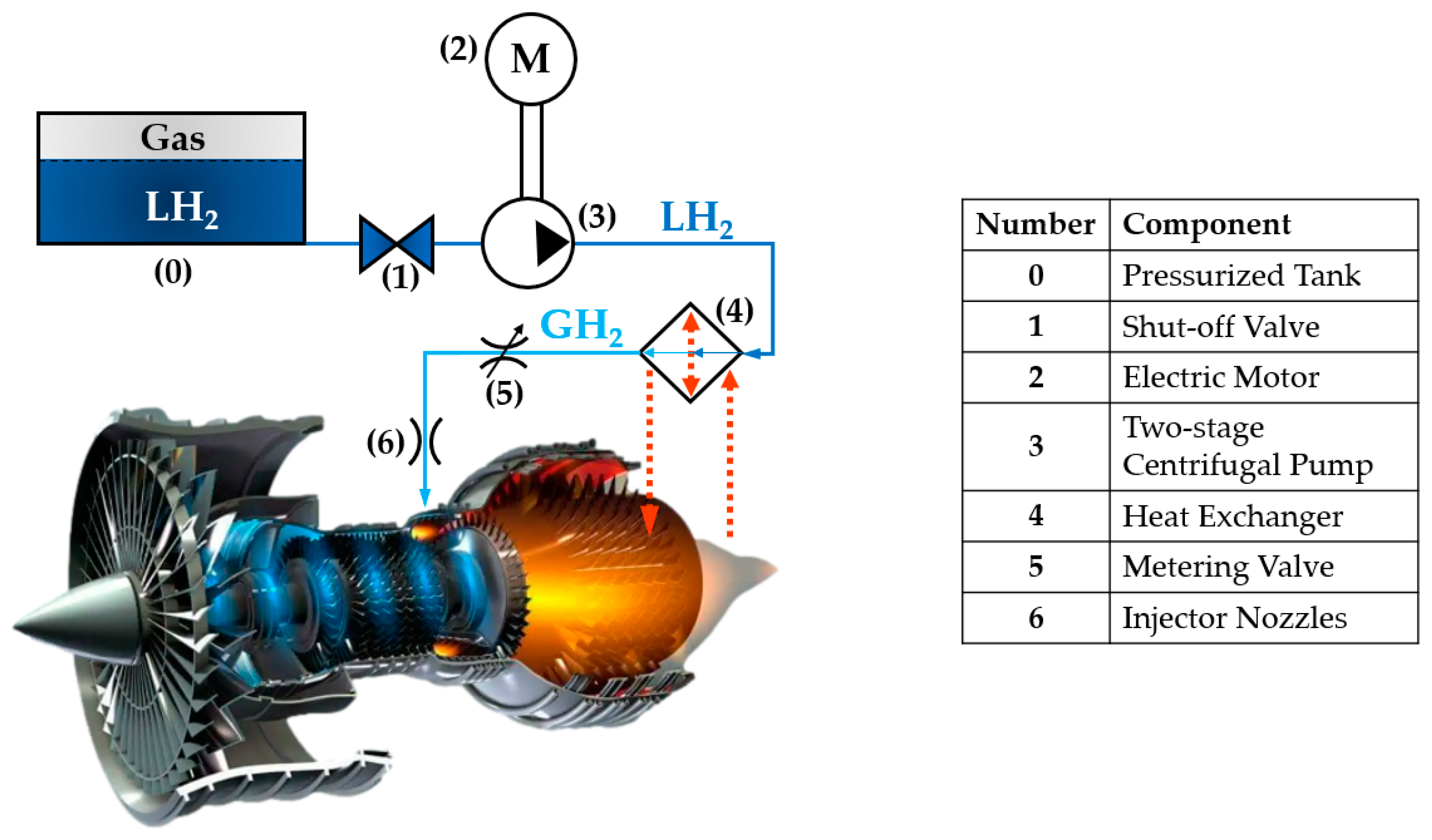
2. Heat Exchanger Layout

As shown in Figure 1, LH2 vaporises upstream of the metering system via a heat exchanger (4), which uses heat from the exhaust gases exiting the turbine to convert H2 from its liquid form (LH2) to a gaseous form (GH2).
The proposed heat exchanger design, depicted in Figure 2, consists of three subunits (recovery heater, main heater, and pre-heater) and incorporates two separate fluid circuits: nitrogen (N2) and hydrogen (H2) circuit. The following concern the fluid circuits:
N2 circuit: N2, a safe and inert gas with excellent thermophysical properties, is widely used in high-performance heat exchangers [42,43]. Specifically, N2 is particularly suitable for use with H2 under supercritical conditions, as its critical temperature is moderately higher than that of H2 and, for both fluids, slightly supercritical operative pressures are employed. This aspect makes N2 a suitable carrier fluid, favoured over commonly used alternatives like water, ethylene, and glycol, as their critical temperatures are excessively higher compared to that of H2, thus not allowing a correct heat exchange between the fluids in the exchanger. In this system, N2 operates within a closed-loop circuit as follows:
  • It absorbs heat from the turbine’s exhaust gases (EGs), raising its temperature;
  • This energy is then transferred to the H2 circuit to heat GH2 to high temperatures;
  • After completing the heat exchange, N2 is recirculated and reheated by the EGs, enabling continuous operation.
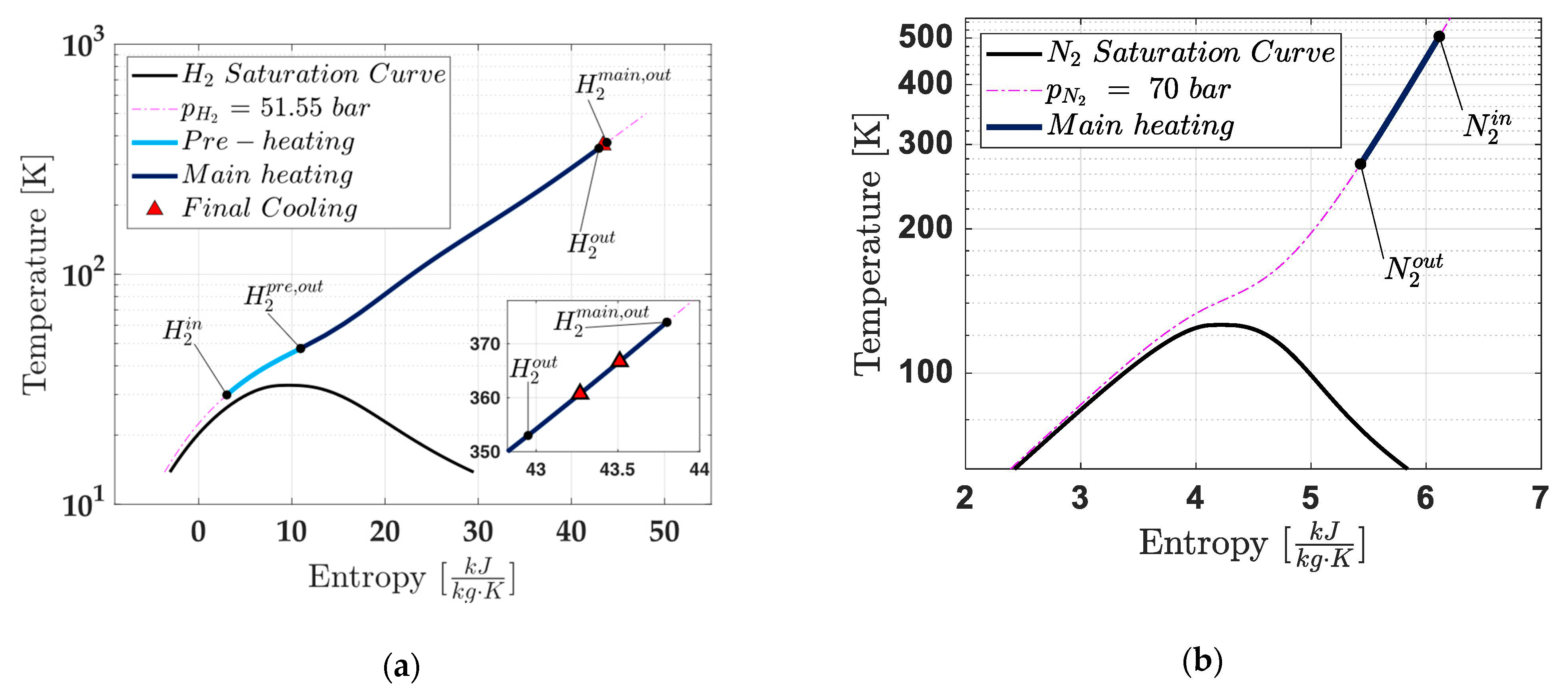
H2 circuit: This circuit ensures the complete phase change of H2 from liquid form (LH2) to gaseous form (GH2) while achieving the desired thermodynamic conditions for metering. Key processes include the following:
  • Pre–Heating: LH2 is initially vaporised using a portion of the heat from high-temperature GH2;
  • Main Heating: The resulting GH2 is further heated through energy transfer from the N2 circuit;
  • Final Cooling: A portion of the high-temperature GH2’s energy is used to vaporise incoming LH2. After this step, the GH2 exits the heat exchanger at the precise thermodynamic conditions required for metering.
The three subunits of the heat exchanger are detailed below:
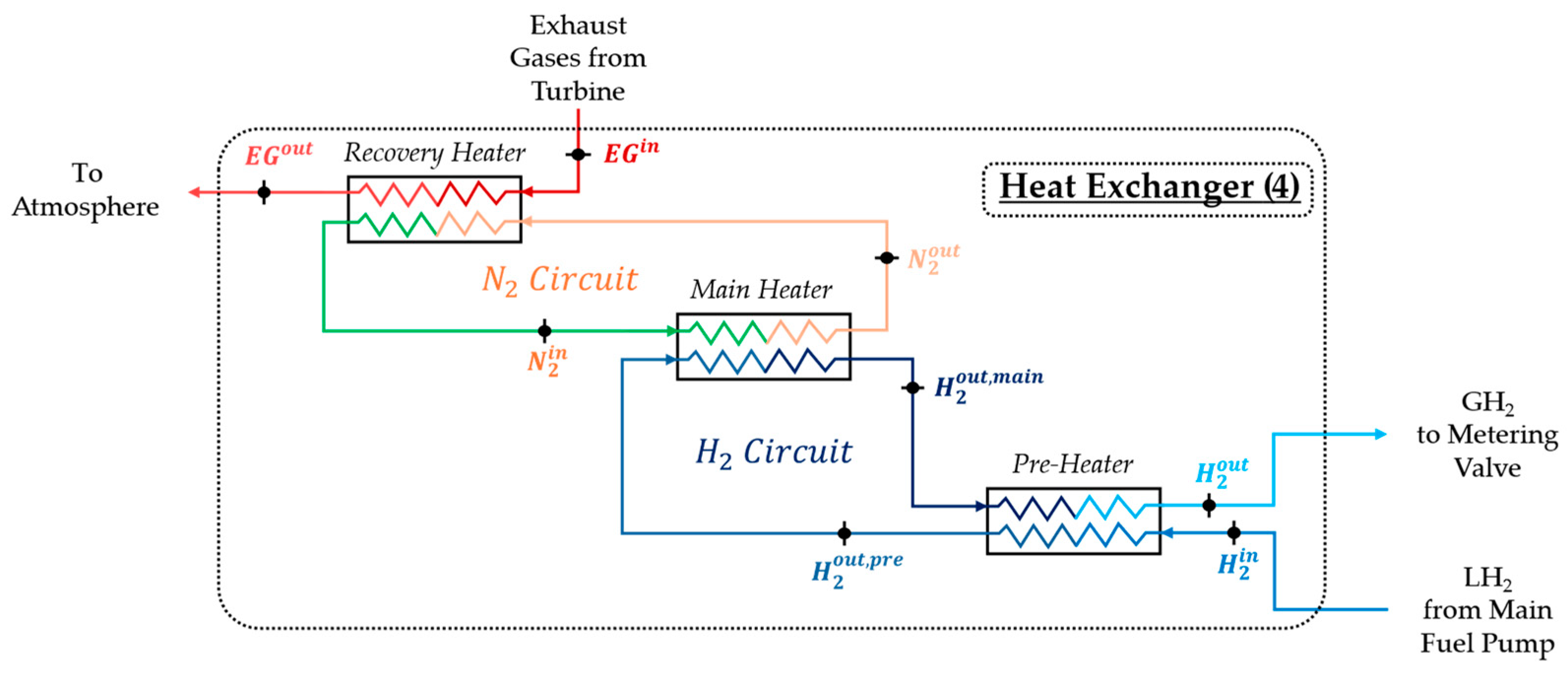
  • Recovery Heater: The first subunit, the recovery heater, captures thermal energy from the EGs leaving the turbine ( E G in ), which retain significant heat. The hot EGs transfer this heat to N2, increasing its temperature ( N 2 in ). After the heat exchange, the EGs are discharged into the atmosphere ( E G out ) ;
  • Main Heater: The high-temperature N2 exiting the recovery heater ( N 2 in ) flows into the second subunit, called the main heater, where it transfers heat to the H2. This H2, already in gaseous form due to vaporisation by the third subunit (the pre-heater) in the H2 circuit ( H 2 out , pre ), receives additional heat from the N2, further increasing its temperature ( H 2 out , main ). Since the N2 circuit is closed, the cooled nitrogen ( N 2 out ) exits the main heater and is recirculated back to the inlet of the recovery heater for reheating;
  • Pre-Heater: LH2 from the main fuel pump enters the heat exchanger ( H 2 in ) and flows into the third subunit, the pre-heater. Within this subunit, high-temperature GH2 from the main heater ( H 2 out , main ) transfers a part of heat to the incoming LH2, causing its vaporisation. After this process, the GH2 from the main heater exits the pre-heater at a slightly reduced temperature ( H 2 out ) and is ready to flow toward the metering system under the required thermodynamic conditions.
It is important to note that numerical modelling has been conducted only for the pre-heater and main heater subunits, assuming negligible pressure losses. As a result, the pressure of H2 in the H2 circuit and N2 in the N2 circuit can be considered constant. This reasonable assumption ensures that pump power consumption remains within acceptable limits, preventing it from rising too high. In this way, the overall system efficiency is not compromised.
For the recovery heater subunit, a possible design is presented in Figure 3. This configuration is included for illustrative purposes only and will neither be designed nor modelled in this preliminary analysis. In this concept, the high-temperature EGs exiting the turbine ( E G in ) transfer heat to N2 flowing through a serpentine tubular pipe. This pipe, integrated into the structure of the outlet nozzle, acts as the recovery heater subunit. After transferring their heat to the N2, the EGs are discharged into the atmosphere ( E G out ) .

3. Heat Exchanger Numerical Model

This section details the numerical model of the heat exchanger architecture, as previously shown in Figure 2. It provides a comprehensive characterisation of the system, excluding the recovery heater, which is included only for illustrative purposes. The analysis addresses the input variables, input thermodynamic and geometric parameters, and output variables that define the system’s performance.
The thermodynamic model leverages the CoolProp libraries [44] for its calculations. In this model, the two heat exchanger subunits are assumed to be adiabatic to the environment, a valid assumption given that these devices must be effectively insulated using vacuum systems.
The model is structured into three main parts: first, the temperature calculations are detailed (Section 3.1); second, the heat transfer coefficients are described (Section 3.2); and finally, the heat exchanger key performance parameters are characterised (Section 3.3). A schematic representation at the end of this section summarises the flow of calculations and parameter interrelations.

3.1. Calculation of the Temperatures

Since the recovery heater subunit is included solely to illustrate the heat recovery mechanism from EGs, this study will focus on modelling the remaining two heat exchanger subunits. Each subunit will be represented with four ports, and the corresponding thermodynamic states will be considered.
All thermodynamic calculations are performed using the CoolProp thermodynamic libraries, which are open-source and widely used due to their thorough validation, as shown in [44]. These libraries have the capability to model over 120 fluids with real gas state equations, including HEOS, PR, and SRK [44].
It is important to note that, when referring to H2, parahydrogen has been considered for these calculations. This choice is driven by the fact that LH2 storage requires the fuel to withstand boil-off, a condition that only parahydrogen can meet [45]. Moreover, at 20 K, parahydrogen concentration exceeds 98%, making the presence of orthohydrogen (around 2%) negligible [46]. However, the spontaneous conversion from ortho to para form occurs very slowly, making catalytic conversion unavoidable in hydrogen liquefaction processes [47].
Another key point of this analysis to highlight is that the operating pressures of both fluids in this study considered in the study (N2 and H2) are maintained above the critical limit (supercritical conditions) to prevent any two-phase behaviour during the heat exchange process.
The inputs for the calculation are as follows: for the H2 circuit, the required thermodynamic parameters are the hydrogen mass flow rate ( m ˙ H 2 ), the inlet and outlet temperatures of hydrogen at the heat exchanger ( T H 2 in , T H 2 out ) and the hydrogen pressure ( p H 2 ) [32,33]. For the N2 circuit, the input thermodynamic parameters include the inlet and outlet temperatures of nitrogen at the main heater subunit ( T N 2 in , T N 2 out ) and the nitrogen pressure ( p N 2 ). Additionally, the temperature difference between the inlet temperature of nitrogen and the hydrogen outlet temperature at the main heater subunit ( Δ T N 2 in H 2 out , main ) is required.
Using these inputs, the nitrogen mass flow rate ( m ˙ N 2 ), the main heater hydrogen outlet enthalpy ( h H 2 out , main ) and the pre-heater hydrogen outlet enthalpy ( h H 2 out , pre ) can be evaluated from the following equations, which describe the power balance for the main heater subunit (1), the pre-heater subunit (2), and the temperature difference between the inlet temperature of nitrogen and the hydrogen outlet temperature at the main heater (3).
m ˙ N 2 h N 2 in   h N 2 out = m ˙ H 2 h H 2 out , main h H 2 out , pre ,
h H 2 out , main   h H 2 out = h H 2 out , pre   h H 2 in ,
Δ T N 2 in H 2 out , main = T N 2 in T H 2 out ,   main ,
where
  • h N 2 in and h H 2 in are the enthalpies for N2 at the inlet of the main heater subunit and for H2 at inlet of the heat exchanger, respectively;
  • h N 2 out and h H 2 out are the enthalpies for N2 at the outlet of the main heater subunit and for H2 at the outlet of the heat exchanger, respectively;
  • T H 2 out ,   main is the temperature associated with h H 2 out , main .
Specifically, to solve these equations, the CoolProp libraries are used to calculate the enthalpies required for Equations (1) and (2). Once the enthalpies are obtained ( h H 2 out , main , h H 2 out , pre ), CoolProp is used again to calculate the associated temperatures ( T H 2 out , main , T H 2 out , pre ), which are then used to determine the temperature profile inside the pipes (for both subunits). Figure 4 illustrates qualitatively the heat exchange process occurring in the pre-heater and main heater subunits.
The technology at the core of this study is the pipe-in-pipe technology, where the internal pipes are enclosed within the external ones. In both heat exchanger subunits, the hot fluid flows inside the internal pipe, while the cold fluid circulates in the space between the internal and external pipes. This configuration offers advantages in terms of compactness and reduced system weight. The system geometry is shown in Figure 5 where d i , i represents the internal diameter of the internal pipe, d e , i represents the external diameter of the internal pipe, d i , e represents the internal diameter of the external pipe and d e , e represents the external diameter of the external pipe. The authors are unaware of any previous market applications of this technology, making it a novel proposal. The number of pipes ( n t ) is the same for both the main heater and pre-heater subunits.
All considerations regarding the thermodynamic states must align with the material strength of the pipes (for both subunits). The pipes need to withstand the pressure imposed by the system to prevent any potential breakdowns. To ensure that the chosen material can handle the required pressure, a law governing the minimum required thickness for a pressurised vessel is applied, specifically the Mariotte’s law which is shown in the following equation:
t     p d i 2 σ yield α ,
where t is the minimum thickness required for the generic tube, p is the pressure acting on the pipe walls, d i is the internal diameter of the generic pipe, σ yield is the yield stress of the material and α is the Mariotte safety coefficient.
Since the two heat exchanger subunits (namely, the pre-heater and the main heater) use the pipe-in-pipe technology for their pipe configuration, it is important to specify the hot and cold fluids in each subunit. For this reason, Table 2 below details, for each subunit, the hot fluid (denoted by the subscript “h”) and the cold fluid (denoted by the subscript “c”).
The flow area for both the cold fluid and the hot fluid can be calculated as:
A h = π d i , i 2 4 ,
A c = π d i , e 2   d e , i 2 4 ,
where A h represents the flow area for the hot fluid, while A c represents the flow area for the cold fluid. By means of Equations (5) and (6), the hydraulic diameter for the hot fluid d h h and the hydraulic diameter for the cold fluid d h c can be obtained as follows:
d h h = 4 A h π d i , i ,
d h c = 4 A c π ( d i , e + d e , i ) ,
In order to trace the temperature profile along the pipes, they can be ideally divided into modules, with constant properties assumed for each module. In this analysis, the number of modules is imposed to be n = 50 for both subunits. In each module, the cold fluid undergoes a temperature variation given by:
Δ T c = T c out     T c in n ,
where T c out and T c in represent the outlet temperature and the inlet temperature of the generic cold fluid. A single module can be schematically represented in Figure 6, where T in , h i , T out , h i , T in , c i , T out , c i and ( Δ x ( i are the input and output temperature for the hot fluid, the input and output temperature for the cold fluid, and the length of the i-th module, respectively.
The outlet temperature of the cold fluid in each module i (i = 1, …, n) is calculated as follows:
T out , c i = T in , c i + Δ T c ,
T in , c i = T out , c i 1 ,
where T in , c 1 T c in and T out , c n     T c out . For the pre-heater T c in T H 2 in , while for the main heater T c in T H 2 out , pre . Similarly, for the pre-heater T c out T H 2 out , pre , while for the main heater T c out T H 2 out , main . Once T in , c i and T out , c i are known, CoolProp libraries can be used to calculate the corresponding enthalpies h in , c i and h out , c i . The values of the latter can be used to calculate the thermal power absorbed by the cold fluid in a single module:
Q ˙ exc i = m ˙ c h out , c i h in , c i ,
where m ˙ c represents the mass flow rate of the generic cold fluid. Since the thermal power absorbed by the cold fluid is equal to the thermal power provided by the hot fluid, the inlet enthalpy and the outlet enthalpy of the hot fluid can be calculated for each module (i) as follows:
h in , h i = h out , h i + Q ˙ exc i m ˙ h ,
h out , h i = h in , h i 1 ,
where m ˙ h represents the mass flow rate for the hot fluid. Similarly to the cold fluid, when i = 1 , h out , h 1 h h out , where h h out is the outlet enthalpy for the generic hot fluid. For the pre-heater h h out h H 2 out , while for the main heater h h out h N 2 out . Consequently, once h out , h i and h in , h i have been determined in each module (i), the temperatures of the hot fluid ( T out , h ) i and ( T in , h ) i can be calculated in each module (i), by using the libraries of CoolProp, as a function of pressure and enthalpy.

3.2. Calculation of the Heat Transfer Coefficients

After the temperature profile along the pipes is traced, it is possible to calculate the heat transfer coefficients, with reference to the average fluid properties of each module (i), which are defined for cold fluid ( T c ¯ ) i and hot fluid ( T h ¯ ) i as follows:
( T h ¯ ) i = ( T in , h ) i + ( T out , h ) i 2 ;   ( T c ¯ ) i = ( T in , c ) i + ( T out , c ) i 2 ,
Once again, by means of CoolProp libraries, once the average temperatures are obtained for each module (i), it is also possible to calculate the following:
  • The average densities of the hot and cold fluids ( ρ h ¯ i , ρ c ¯ i ) ;
  • The average thermal conductivities of the hot and cold fluids ( ( λ h ¯ ) i , ( λ c ¯ ) i ) ;
  • The average viscosities of the hot and cold fluids ( ( μ h ¯ ) i , ( μ c ¯ ) i ) ;
  • The average specific heats of the hot and cold fluids ( ( cp h ¯ ) i , ( cp c ¯ ) i ) .
Another property to be calculated in each module (i) is the average velocity for both the hot fluid and the cold fluid:
( V x ¯ ) i = m ˙ x n t · ( ρ x ¯ ) i · A x ,
where either x = h (hot fluid) or x = c (cold fluid).
Along these average thermodynamic and cinematic parameters, also the average Reynolds number and the average Prandtl number of the hot and cold fluids can be calculated in each module (i) as:
( Re x ¯ ) i = ( V x ¯ ) i · ( ρ x ¯ ) i · d h , x ( μ x ¯ ) i ,
( Pr x ¯ ) i = ( μ x ¯ ) i · ( cp x ¯ ) i ( λ x ¯ ) i ,
The Average Nusselt number in each module (i) is expressed as a function of the average Reynolds number as:
  • when R e x ¯ i < 2300   N u x ¯ i = 4.36
  • when 2300 < R e x ¯ i < 10 6 , the Gnielinski correlation can be used
  • when R e x ¯ i > 10 6 , the Chilton–Coulburn correlation can be used.
The following Equation (19) encloses all the cases described above:
( Nu x ¯ ) i =                     4.36 ,                                                                                                                                     i f   Re x ¯ i < 2300 ( ξ ) i 8 · ( Re x ¯ i 1000 ) · Pr x ¯ i ) 1 + 12.7 ( ξ ) i 8 0.5 ·   Pr x ¯ i 2 / 3 1 ,                                         i f   2300 <   Re x ¯ i < 10 6                             0.023 · Re x ¯ i 0.8 · ( Pr x ¯ ) i 1 / 3 ,                                                   if   Re x ¯ i > 10 6
where ξ i represents the friction factor in each module (i), which can be calculated as:
( ξ ) i = ( 1.82 · log Re x ¯ i   1.64 ) 2
Equations (19) and (20) are well established and widely used in the literature [48,49]; therefore, they are to be considered reliable for fully developed (hydrodynamically and thermally) flow.
Finally, once all these average quantities are available, the convective heat exchange coefficients in each module (i), for the hot fluid h h ¯ i and cold fluid h c ¯ i , can be obtained as:
h h ¯ i = Nu h ¯ i · ( λ h ¯ ) i d h , h   ;   h c ¯ i = Nu c ¯ i · ( λ c ¯ ) i d h , c

3.3. Calculation of the Performance Parameters

The knowledge of the convective heat exchange coefficients and the temperatures of the hot and cold fluids allows for the determination of the mean heat transfer coefficient U i and the logarithmic mean temperature difference ( Δ T ) i in each module (i) with the following equations:
( U ) i = 1 1 h c ¯ i + 1 h h ¯ i · d i , i d e , i + d e , i   ln d e , i d i , i 2     λ
( Δ T ) i = [ ( T in ,   h ) i     ( T out , c ) i ] [ ( T out ,   h ) i     ( T in , c ) i ] ln ( T in , h ) i ( T out , c ) i ( T out , h ) i ( T in , c ) i
where λ is the thermal conductivity of the material constituting the pipes. In this way, it is possible to determine the length of each module ( Δ x i ), and thus the overall length of both heat exchanger subunits (pre-heater and main heater):
Δ x i = ( Q ˙ exc ) i π · d e , i · n t · U i · ( Δ T ) i
L y = i = 1 n Δ x i
where “y” is a generic subscript indicating the pre-heater when y = pre and the main heater when y = main. To represent the total length of the pipes, considering the lengths of both subunits, it is defined as: L tot = L pre + L main .
The pressure drop is calculated using the Darcy formula for both the hot ( Δ p h ) and cold ( Δ p c ) fluids (for both subunits), based on the average properties of the fluids, as follows:
Δ p h = i = 1 n 1   2 · ( f h ) i ·   ( V h ¯ ) i 2 · ( ρ h ¯ ) i · Δ x i d h , h
Δ p c = i = 1 n 1   2 · ( f c ) i ·   ( V c ¯ ) i 2 · ( ρ c ¯ ) i · Δ x i d h , c
where f h i and f c i are the friction factors in rough pipes for the hot and cold fluids, respectively, calculated based on the value of the average Reynold number in each module (i):
f x i = 64 ( Re x ¯ ) i ,                                                                                                     i f   ( Re x ¯ ) i < 2300 1 1.8 · log Ɛ d h , x 3.7 1.11 + 6.9 Re x ¯ i 2 ,         i f   ( Re x ¯ ) i 2300
where the first expression represents laminar flow condition, while the second expression (also known as Haaland formula) is representative of turbulent flow and ε is the roughness of the tubes.
In order to calculate the mass of both the heat exchanger subunits, the following equation is applied:
m y = V y ρ mat
where ρ mat is the density of the selected material and V y indicates the volume of the pipes, which is evaluated as:
V y = π d e , e 2     d i , e 2 + d e , i 2 d i , i 2 4 L y
Similarly to the comprehensive length of the pipes, the total mass of the latter can be indicated as: m tot = m pre + m main , while the total volume of the pipes: V tot = V pre + V main .
Figure 7 provides a simplified algorithm flow diagram to represent the flow of calculations.

4. Results

This section evaluates the feasibility of the proposed heat exchanger architecture using the thermodynamic model described earlier. In the calculation, the pre-heater is divided into 50 modules, as is the main heater. Table 3 summarises the input parameters for the H2 circuit, including the inlet LH2 temperature to the heat exchanger, the outlet GH2 temperature from the heat exchanger, as well as the H2 circuit pressure and mass flow rate. These parameters are derived from [32,33], which introduced and modelled the innovative hydrogen-fuelled aircraft system depicted in Figure 1 using Matlab/Simulink. The numerical model in these studies was validated by comparing simulated operating conditions with data from the literature [50], focusing on the take-off phase.
Building on this foundation, the current study aims to design the heat exchanger architecture, previously illustrated in Figure 2 (taking into account only the pre-heater and main heater subunits), suitable for integration into the innovative hydrogen-fuelled aircraft system, with particular attention to the take-off phase. This phase is identified as the most critical for optimising the dimensions and performance parameters of the heat exchanger [50].
Specific assumptions were made to define the operating thermodynamic conditions of the N2 circuit as follows:
  • The N2 inlet temperature to the main heater, T N 2 in , was set to 504 K. This value represents the temperature achieved by N2 after heat exchange with the EGs in the recovery heater;
  • The pressure in the N2 circuit was set to 70 bar.
These N2 input thermodynamic parameters, summarised in Table 4, were chosen to ensure N2 in a supercritical gaseous state at high temperature, optimising its thermophysical properties for effective heat transfer.
To comply with the temperature limits outlined in ASME B31.12 (Standard on Hydrogen Piping and Pipelines), austenitic stainless steels (300 series) are recommended for piping in both GH2 and LH2 systems, rather than other materials like aluminium, which, despite having better thermal conductivity, offers lower corrosion resistance and mechanical strength [51]. Among the various stainless steel grades, 316/316 L is preferred due to its superior stability and resistance to H2 embrittlement, especially under high-pressure and temperature H2 exposure [52]. This balance of thermal performance and structural reliability makes it the ideal choice for this application.
For the pre-heater and main heater subunits, piping made from stainless steel 316 was chosen. Using its material properties, along with the pipe key geometric parameters provided as model inputs, the minimum pipe thickness was calculated based on the Mariotte formula (outlined earlier in Section 3.1, Equation (4)).
It is important to remember that in the pipes of the pre-heater subunit, the hot fluid (h) is the high-temperature GH2 exiting the main heater subunit ( H 2 out , main ), while the cold fluid (c) is the LH2 supplied from the main fuel pump ( H 2 in ). Conversely, in the pipes of the main heater subunit, the cold fluid (c) is the vaporised H2 leaving the pre-heater subunit ( H 2 out , pre ), and the hot fluid (h) is the high-temperature N2 from the recovery heater subunit ( N 2 in ), where it absorbs heat from EGs.
The material properties of stainless steel 316/316L are detailed in Table 5, while the considered geometric parameters of the pipes and the calculated minimum pipe thickness are summarised in Table 6.
To identify the optimal design point for the heat exchanger, minimising its performance parameters, namely the total pipes length ( L tot = L pre + L main ) and mass ( m tot = m pre + m main ), three key input parameters of the thermodynamic model were varied:
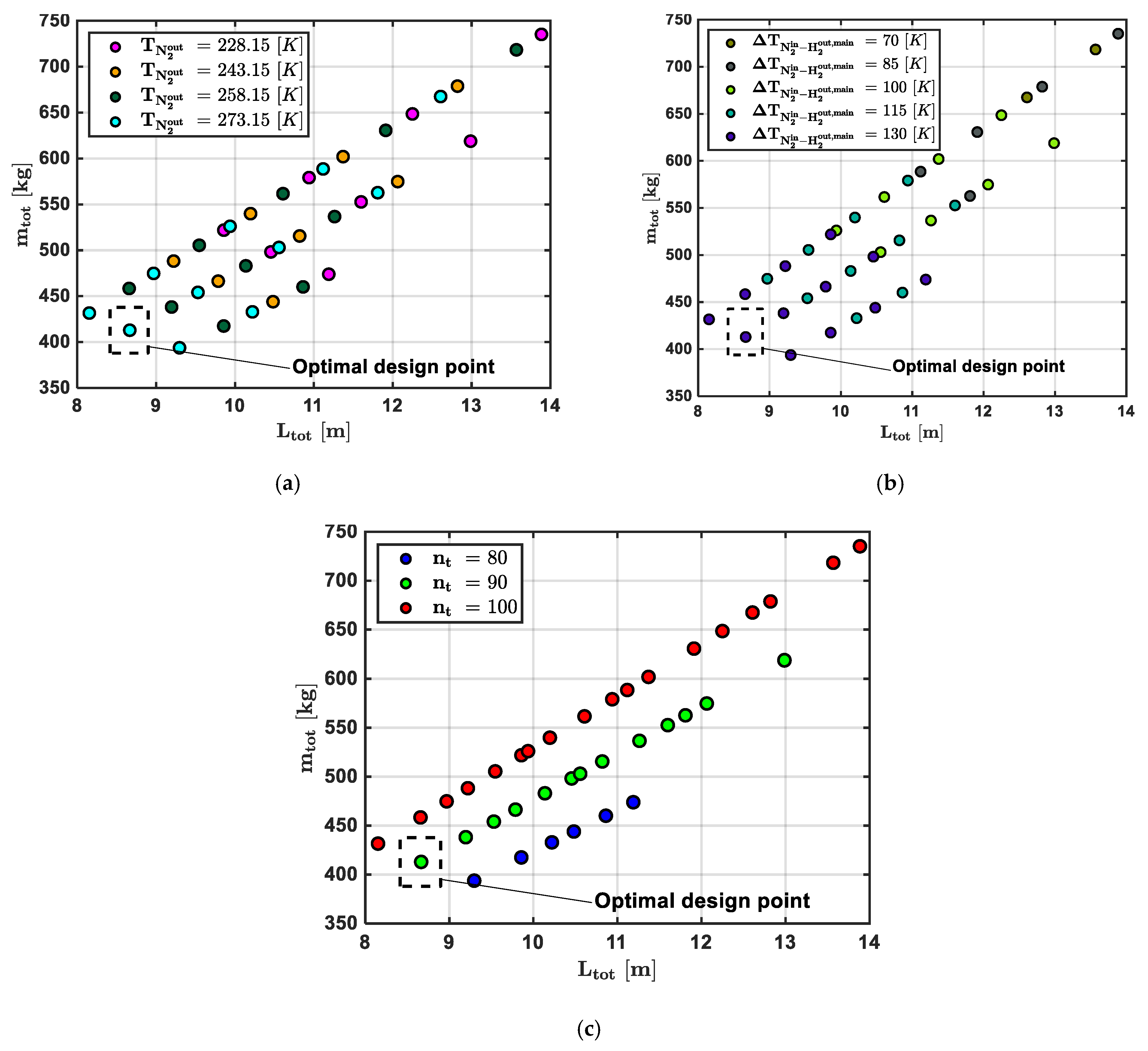
  • The outlet N2 temperature from the main heater ( T N 2 out ).
  • The temperature difference between the inlet N2 temperature to the main heater and the outlet H2 temperature from the main heater ( Δ T N 2 in H 2 out , main ).
  • The number of pipes in both the pre-heater and main heater subunits ( n t ).
The process was conducted using Esteco modeFRONTIER 2019 software [53], with a constraint that the pressure drops across the pipes remain below Δp ≤ 0.1 bar. This applied to both the cold fluids (denoted as “c”) and hot fluids (denoted as “h”) in the respective subunits, ensuring that the heat exchange process in both subunits could be treated as isobaric.
Table 7 provides a summary of the input variables involved in the calculation, including their value ranges, variation steps and number of points considered. The constraints applied during the process are outlined in Table 8. A total of 60 design points were generated, which can be easily obtained by multiplying the individual number of points for each input variable.
The results, showing the influence of these input variables ( T N 2 out , Δ T N 2 in H 2 out , main ) and ( n t ) on the performance parameters ( L tot and m tot ) are presented in Figure 8, which highlights the selected optimal design point. The analysis reveals that higher values of the thermodynamic variables ( T N 2 out and Δ T N 2 in H 2 out , main ) combined with intermediate values of the geometric variable ( n t ) effectively minimise both the total length ( L tot ) and mass ( m tot ) of the heat exchanger. Based on this, the optimal design point has been selected with T N 2 out = 273.15 K, T N 2 in H 2 out , main = 130 K and n t = 90. Table 9 specifies the thermodynamic and geometric input variable values corresponding to the optimal design point.
Considering the thermodynamic input values for N2 corresponding to the optimal design point from Table 9 and the assumed values from Table 4, along with the input values for H2 provided in Table 3 (to meet the take-off phase requirements), the corresponding enthalpies for the H2 and N2 circuits, as calculated by the thermodynamic model using CoolProp, are presented in Table 10. It is important to note that the thermodynamic model also incorporates the input geometric parameters of the pipes (for both subunits) from Table 6, considers the properties of stainless steel 316 for the pipes (for both subunits) from Table 5, and uses the optimal number of pipes (for both subunits), as previously obtained and specified in Table 9.
Additionally, the results from solving Equations (1)–(3), as described earlier in Section 3.1, are presented in Table 11. These outcomes, which are detailed below, also include the thermal powers absorbed/released by the cold/hot fluids in both subunits:
  • The temperatures and enthalpies of H2 at the outlets of the pre-heater and main heater subunits.
  • The required mass flow rate of N2 in the main heater subunit.
  • The thermal power is absorbed by LH2 and released by GH2 in the pre-heater subunit.
  • The thermal power is absorbed by GH2 and released by N2 in the main heater subunit.
These data provide a comprehensive evaluation of the heat exchange process.
With the thermodynamic data for the heat exchange in both subunits fully determined, the trends of the thermodynamic states of H2 and N2 throughout the pre-heater and main heater subunits can be analysed. Figure 9 illustrates these thermodynamic transformations for both fluids on a temperature–entropy (T-s) diagram, with Figure 9a detailing the transformations for H2 and Figure 9b for N2. It is evident that no two-phase or cyclic behaviours occur during heat exchange, as both fluids are handled at supercritical pressure values.
Furthermore, Figure 10 illustrates the temperature–thermal power plots for both the pre-heater (Figure 10a) and the main heater (Figure 10b), based on the identified optimal design point. It is evident that this depiction, which includes the calculated data (quantitative graphs), is analogous to Figure 4, which instead presents a qualitative graph.
In conclusion, Table 12 summarises the key performance parameters of the heat exchanger for both the pre-heater and main heater subunits, along with the pressure drop across the pipes for both the hot and cold fluids.
The length of the pre-heater is smaller (0.141 m) because the temperature difference between the two fluids is larger in the main heater. In both subunits, the pressure drops are negligible, as the optimal design point analysis was constrained to ensure a pressure drop of Δp ≤ 0.1 bar for the hot and cold fluid.
Based on the values in Table 12, the total length, mass, and volume of the heat exchanger pipes are L tot = 8.666   m , m tot = 412 . 9   kg and V tot = 5.69 × 10 4   m 3 , respectively. These performance parameters are suitable for a fuel system application.
Moreover, with the heat exchanger’s thermal power requirement at approximately 2 MW [34] and the theoretical power generated by fuel combustion at around 48 MW, it is possible to conclude that the system is feasible. Specifically, the novel cryogenic heat exchanger operates with a negligible cost for energy use, as it only needs 4% of the thermal power generated by the engine. This is particularly efficient when considering that the overall efficiency of an aircraft engine is around 40%.

5. Conclusions

This paper proposed a nitrogen–hydrogen heat exchanger, which can be employed in an innovative hydrogen-propelled aircraft fuel system recently proposed by the authors. The novel cryogenic heat exchanger is designed to vaporise and superheat LH2 using heat recovered from the turbine EGs of an aircraft. Specifically, the study focused on the design of the heat exchanger architecture, modelling the pre-heater and main heater subunits, with particular attention to the performance requirements for the critical take-off phase. The system employed a pipe-in-pipe architecture and was modelled using a comprehensive thermodynamic model. The latter incorporated rigorously validated equations and utilised the CoolProp libraries for accurate thermodynamic calculations.
Austenitic stainless steel 316 was selected for the piping of both heat exchanger subunits due to their resistance to H2 embrittlement and stability under high pressure.
The heat exchanger design was optimised by varying three key input parameters: the outlet N2 temperature from the main heater ( T N 2 out ), the temperature difference between the inlet N2 and outlet H2 temperatures at the main heater ( Δ T N 2 in H 2 out , main ), and the number of pipes in both the pre-heater and main heater subunits ( n t ). The process was conducted using Esteco modeFRONTIER 2019 software, with a constraint that pressure drops across the pipes remained below Δp ≤ 0.1 bar for both cold and hot fluids. This ensured that the heat exchange process in both subunits could be treated as isobaric.
The results of calculations showed that for the optimal design point ( T N 2 out = 273.15   K , Δ T N 2 in H 2 out , main = 130   K and n t = 90 ) the performance parameters were L tot = 8.666   m , m tot = 412 . 9   kg and V tot = 5.69 ×   10 4 m 3 , respectively, which demonstrated the plant’s feasibility for aircraft fuel system applications. Additionally, the system feasibility is also supported by the fact that the heat exchanger requires approximately 2 MW of thermal power, which is well within the available 48 MW generated by fuel combustion.
In conclusion, this work provides a robust foundation for future advancements in sustainable aviation, as it provides the design of one of the key components of the next hydrogen-propelled aircraft. Further studies will include a thermal stress analysis to assess the impact of temperature gradients on the strength and lifespan of pipeline materials (for both subunits) during the heat exchange process.

Author Contributions

Conceptualisation, F.S., V.D.D., P.T., E.D. and R.A.; methodology, F.S., V.D.D., P.T., E.D. and R.A.; software, F.S., V.D.D., P.T., E.D. and R.A.; validation, F.S., V.D.D., P.T., E.D. and R.A.; formal analysis, F.S., V.D.D., P.T., E.D. and R.A.; investigation, F.S., V.D.D., P.T., E.D. and R.A.; resources, F.S., V.D.D., P.T., E.D. and R.A.; data curation, F.S., V.D.D., P.T., E.D. and R.A.; writing—original draft preparation, F.S., V.D.D., P.T., E.D. and R.A.; writing—review and editing, F.S., V.D.D., P.T., E.D. and R.A.; visualisation, F.S., V.D.D., P.T., E.D. and R.A.; supervision, F.S., V.D.D., P.T., E.D. and R.A.; project administration, F.S., V.D.D., P.T., E.D. and R.A.; funding acquisition, F.S., V.D.D., P.T., E.D. and R.A. All authors have read and agreed to the published version of the manuscript.

Funding

This work has been supported under the National Recovery and Resilience Plan (NRRP), Mission 4, Component 2, Investment 1.4—Call for tender No. 3138 of 16 December 2021 of the Italian Ministry of University and Research, funded by the European Union—NextGenerationEU [Award Number: CNMS named MOST, Concession Decree No. 1033 of 17 June 2022, adopted by the Italian Ministry of University and Research, CUP: D93C22000410001, Spoke 14 ‘‘Hydrogen and New Fuels’’].

Data Availability Statement

The original contributions presented in the study are included in the article, further inquiries can be directed to the corresponding author.

Conflicts of Interest

The authors declare no conflicts of interest.

References

  1. International Civil Aviation Organization Industry High Level Group. Aviation Benefits Report 2019. 2019. Available online: https://www.icao.int/sustainability/Documents/AVIATION-BENEFITS-2019-web.pdf (accessed on 30 July 2024).
  2. Lee, D.S.; Fahey, D.W.; Skowron, A.; Allen, M.R.; Burkhardt, U.; Chen, Q.; Doherty, S.J.; Freeman, S.; Forster, P.M.; Fuglestvedt, J.; et al. The contribution of global aviation to anthropogenic climate forcing for 2000 to 2018. Atmos. Environ. 2021, 244, 117834. [Google Scholar] [CrossRef] [PubMed]
  3. Undertaking, H.J. Hydrogen Powered Aviation: A Fact-Based Study of Hydrogen Technology, Economics, and Climate Impact by 2050. 2020. Available online: https://www.h2knowledgecentre.com/content/researchpaper1126 (accessed on 20 January 2025).
  4. Oesingmann, K.; Grimme, W.; Scheelhaase, J. Hydrogen in aviation: A simulation of demand, price dynamics, and CO2 emission reduction potentials. Int. J. Hydrogen Energy 2024, 64, 633–642. [Google Scholar] [CrossRef]
  5. Gössling, S.; Humpe, A. The global scale, distribution and growth of aviation: Implications for climate change. Glob. Environ. Change 2020, 65, 102194. [Google Scholar] [CrossRef] [PubMed]
  6. Lee, D.S.; Fahey, D.W.; Forster, P.M.; Newton, P.J.; Wit, R.C.; Lim, L.L.; Owen, B.; Sausen, R. Aviation and global climate change in the 21st century. Atmos. Environ. 2009, 43, 3520–3537. [Google Scholar] [CrossRef] [PubMed]
  7. Valdes, R.M.A.; Burmaoglu, S.; Tucci, V.; da Costa Campos, L.M.B.; Mattera, L.; Comendador, V.F.G. Flight path 2050 and ACARE goals for maintaining and extending industrial leadership in aviation: A map of the aviation technology space. Sustainability 2019, 11, 2065. [Google Scholar] [CrossRef]
  8. Srinath, A.N.; Pena López, Á.; Miran Fashandi, S.A.; Lechat, S.; di Legge, G.; Nabavi, S.A.; Nikolaidis, T.; Jafari, S. Thermal management system architecture for hydrogen-powered propulsion technologies: Practices, thematic clusters, system architectures, future challenges, and opportunities. Energies 2022, 15, 304. [Google Scholar] [CrossRef]
  9. Kadyk, T.; Schenkendorf, R.; Hawner, S.; Yildiz, B.; Römer, U. Design of fuel cell systems for aviation: Representative mission profiles and sensitivity analyses. Front. Energy Res. 2019, 7, 440189. [Google Scholar] [CrossRef]
  10. Rutherford, D.; Zeinali, M. Efficiency Trends for New Commercial Jet Aircraft 1960–2008. 2009. Available online: https://theicct.org/wp-content/uploads/2021/06/ICCT_Aircraft_Efficiency_final.pdf (accessed on 20 January 2025).
  11. Thapa, N.; Ram, S.; Kumar, S.; Mehta, J. All electric aircraft: A reality on its way. Mater. Today Proc. 2021, 43, 175–182. [Google Scholar] [CrossRef]
  12. Meissner, R.; Sieb, P.; Wollenhaupt, E.; Haberkorn, S.; Wicke, K.; Wende, G. Towards climate-neutral aviation: Assessment of maintenance requirements for airborne hydrogen storage and distribution systems. Int. J. Hydrogen Energy 2023, 48, 29367–29390. [Google Scholar] [CrossRef]
  13. Abrantes, I.; Ferreira, A.F.; Silva, A.; Costa, M. Sustainable aviation fuels and imminent technologies-CO2 emissions evolution towards 2050. J. Clean. Prod. 2021, 313, 127937. [Google Scholar] [CrossRef]
  14. Adler, E.J.; Martins, J.R.R.A. Hydrogen-powered aircraft: Fundamental concepts, key technologies, and environmental impacts. Prog. Aerosp. Sci. 2023, 141, 100922. [Google Scholar] [CrossRef]
  15. Svensson, F.; Hasselrot, A.; Moldanova, J. Reduced environmental impact by lowered cruise altitude for liquid hydrogen-fuelled aircraft. Aerosp. Sci. Technol. 2004, 8, 307–320. [Google Scholar] [CrossRef]
  16. Timmons, D.; Terwel, R. Economics of aviation fuel decarbonization: A preliminary assessment. J. Clean. Prod. 2022, 369, 133097. [Google Scholar] [CrossRef]
  17. Yusaf, T.; Mahamude, A.S.; Kadirgama, K.; Ramasamy, D.; Farhana, K.; Dhahad, H.A.; Talib, A.R. Sustainable hydrogen energy in aviation—A narrative review. Int. J. Hydrogen Energy 2023, 52, 1026–1045. [Google Scholar] [CrossRef]
  18. Donateo, T.; Bonatesta, A.G.; Ficarella, A.; Lecce, L. Energy Consumption and Saved Emissions of a Hydrogen Power System for Ultralight Aviation: A Case Study. Energies 2024, 17, 3272. [Google Scholar] [CrossRef]
  19. Smith, T.D. Hydrogen-Powered Flight. 2005. Available online: https://ntrs.nasa.gov/citations/20050196728 (accessed on 20 January 2025).
  20. Rogers, H.L.; Lee, D.S.; Raper, D.W.; de F. Foster, P.M.; Wilson, C.W.; Newton, P.J. The impacts of aviation on the atmosphere. Aeronaut. J. 2002, 106, 521–546. [Google Scholar] [CrossRef]
  21. Haglind, F.; Hasselrot, A.; Singh, R. Potential of reducing the environmental impact of aviation by using hydrogen Part I: Background, prospects and challenges. Aeronaut. J. 2006, 110, 533–540. [Google Scholar] [CrossRef]
  22. Koroneos, C.J.; Moussiopoulos, N. Cryoplane–Hydrogen vs. kerosene as aircraft fuel. In Proceedings of the 7th International Conference on Environmental Science and Technology, Syros, Greece, 3–6 September 2001; pp. 484–493. [Google Scholar]
  23. Bock, L.; Burkhardt, U. Contrail cirrus radiative forcing for future air traffic. Atmos. Chem. Phys. 2019, 19, 8163–8174. [Google Scholar] [CrossRef]
  24. Winnefeld, C.; Kadyk, T.; Bensmann, B.; Krewer, U.; Hanke-Rauschenbach, R. Modelling and designing cryogenic hydrogen tanks for future aircraft applications. Energies 2018, 11, 105. [Google Scholar] [CrossRef]
  25. Huber, M.L.; Lemmon, E.W.; Bruno, T.J. Surrogate mixture models for the thermophysical properties of aviation fuel Jet-A. Energy Fuels 2010, 24, 3565–3571. [Google Scholar] [CrossRef]
  26. Yamaguchi, M.; Takahashi, K.; Ohmori, T. Thermal conductivity of polyurethane foam at liquid hydrogen temperature region. In Advances in Cryogenic Engineering: Part A; Springer: Boston, MA, USA, 1996; pp. 117–122. [Google Scholar]
  27. Buttner, W.J.; Ciotti, M.; Hartmann, K.; Schmidt, K.; Wright, H.; Weidner, E. Empirical profiling of cold hydrogen plumes formed from venting of LH2 storage vessels. Int. J. Hydrogen Energy 2021, 46, 32723–32734. [Google Scholar] [CrossRef]
  28. Coutinho, M.; Bento, D.; Souza, A.; Cruz, R.; Afonso, F.; Lau, F.; Suleman, A.; Barbosa, F.R.; Gandolfi, R.; Junior, W.A.; et al. A review on the recent developments in thermal management systems for hybrid-electric aircraft. Appl. Therm. Eng. 2023, 227, 120427. [Google Scholar] [CrossRef]
  29. Patrao, A.C.; Jonsson, I.; Xisto, C.; Lundbladh, A.; Lejon, M.; Grönstedt, T. The heat transfer potential of compressor vanes on a hydrogen fueled turbofan engine. Appl. Therm. Eng. 2024, 236, 121722. [Google Scholar] [CrossRef]
  30. Brewer, G.D. Hydrogen Aircraft Technology; CRC Press: Boca Raton, FL, USA, 1991. [Google Scholar] [CrossRef]
  31. ZEROe|Airbus. Available online: https://www.airbus.com/en/innovation/energy-transition/hydrogen/zeroe (accessed on 28 February 2025).
  32. Plummer, A.; Adeyemi, D.; Sell, N.; Sciatti, F.; Tamburrano, P.; Amirante, R. Fuel System Control for Hydrogen-Powered Aircraft. In Proceedings of the 2024 UKACC 14th International Conference on Control (CONTROL), Winchester, UK, 10–12 April 2024; pp. 201–202. [Google Scholar] [CrossRef]
  33. Sciatti, F.; Di Domenico, V.; Zagaria, L.; Adeyemi, D.; Tamburrano, P.; Plummer, A.R.; Sell, N.; Distaso, E.; Amirante, R. Preliminary Design and Modelling of a Hydrogen-Powered Aircraft Fuel System. In Fluid Power Systems Technology; American Society of Mechanical Engineers: New York, NY, USA, 2024; p. V001T01A028. [Google Scholar]
  34. Sciatti, F.; Tamburrano, P.; Distaso, E.; Amirante, R. Modelling of the Entire Aircraft Fuel System Through Simulink for Accurate Performance Evaluation. In Fluid Power Systems Technology; American Society of Mechanical Engineers: New York, NY, USA, 2023; p. V001T01A050. [Google Scholar]
  35. Sciatti, F.; Tamburrano, P.; Distaso, E.; Amirante, R. Digital Hydraulic Technology: Applications, Challenges, and Future Direction. J. Phys. Conf. Ser. 2023, 2648, 012053. [Google Scholar]
  36. Tamburrano, P.; Sciatti, F.; Distaso, E.; Amirante, R. Comprehensive Numerical Analysis of a Four-Way Two-Position (4/2) High-Frequency Switching Digital Hydraulic Valve Driven by a Ring Stack Actuator. Energies 2023, 16, 7355. [Google Scholar] [CrossRef]
  37. Tamburrano, P.; De Palma, P.; Plummer, A.R.; Distaso, E.; Sciatti, F.; Amirante, R. Simulation of a high frequency on/off valve actuated by a piezo-ring stack for digital hydraulics. E3S Web Conf. 2021, 312, 05008. [Google Scholar]
  38. Łapka, P.; Seredyński, M.; Ćwik, A. Preliminary study on supercritical hydrogen and bleed air heat exchanger for aircraft application. Proc. Inst. Mech. Eng. G J. Aerosp. Eng. 2018, 232, 2231–2243. [Google Scholar] [CrossRef]
  39. Vietze, M.; Evrim, C. Development of additively manufactured cryogenic heat exchangers for hydrogen-electric aircraft propulsion. In IOP Conference Series: Materials Science and Engineering; IOP Publishing: Bristol, UK, 2024; p. 012007. [Google Scholar]
  40. Patrao, A.C.; Jonsson, I.; Xisto, C.; Lundbladh, A.; Grönstedt, T. Compact heat exchangers for hydrogen-fueled aero engine intercooling and recuperation. Appl. Therm. Eng. 2024, 243, 122538. [Google Scholar] [CrossRef]
  41. Di Domenico, V.; Tamburrano, P.; Sciatti, F.; Distaso, E.; Foglia, M.M.; Amirante, R. A Novel Hydrogen-Nitrogen Heat Exchanger For Aeronautical Applications. J. Phys. Conf. Ser. 2024, 2893, 012082. [Google Scholar]
  42. Olumayegun, O.; Wang, M.; Kelsall, G. Thermodynamic analysis and preliminary design of closed Brayton cycle using nitrogen as working fluid and coupled to small modular Sodium-cooled fast reactor (SM-SFR). Appl. Energy 2017, 191, 436–453. [Google Scholar] [CrossRef]
  43. Zhang, X.; Tiwari, R.; Shooshtari, A.H.; Ohadi, M.M. An additively manufactured metallic manifold-microchannel heat exchanger for high temperature applications. Appl. Therm. Eng. 2018, 143, 899–908. [Google Scholar] [CrossRef]
  44. Bell, I.H.; Wronski, J.; Quoilin, S.; Lemort, V. Pure and Pseudo-pure Fluid Thermophysical Property Evaluation and the Open-Source Thermophysical Property Library CoolProp. Ind. Eng. Chem. Res. 2014, 53, 2498–2508. [Google Scholar] [CrossRef]
  45. Riaz, A.; Qyyum, M.A.; Hussain, A.; Lee, M. Significance of ortho-para hydrogen conversion in the performance of hydrogen liquefaction process. Int. J. Hydrogen Energy 2023, 48, 26568–26582. [Google Scholar] [CrossRef]
  46. Teng, J.; Wang, K.; Zhu, S.; Bao, S.; Zhi, X.; Zhang, X.; Qiu, L. Comparative study on thermodynamic performance of hydrogen liquefaction processes with various ortho-para hydrogen conversion methods. Energy 2023, 271, 127016. [Google Scholar] [CrossRef]
  47. Yin, L.; Ju, Y. Review on the design and optimization of hydrogen liquefaction processes. Front. Energy 2020, 14, 530–544. [Google Scholar] [CrossRef]
  48. Çengel, Y.A. Introduction to Thermodynamics and Heat Transfer; McGraw-Hill: New York, NY, USA, 2008. [Google Scholar]
  49. Taler, D.; Taler, J. Simple heat transfer correlations for turbulent tube flow. E3S Web Conf. 2017, 13, 02008. [Google Scholar] [CrossRef]
  50. Brewer, G.D. Hydrogen Aircraft Technology; Routledge: New York, NY, USA, 2017. [Google Scholar]
  51. Liu, J.; Zhao, M.; Rong, L. Overview of hydrogen-resistant alloys for high-pressure hydrogen environment: On the hydrogen energy structural materials. Clean Energy 2023, 7, 99–115. [Google Scholar] [CrossRef]
  52. Marchi, C.S.; Somerday, B.P. Comparison of Stainless Steels for High-Pressure Hydrogen Service. In Pressure Vessels and Piping Division (Publication) PVP; American Society of Mechanical Engineers: New York, NY, USA, 2014; Volume 6B. [Google Scholar] [CrossRef]
  53. Available online: https://engineering.esteco.com/modefrontier/ (accessed on 10 April 2024).
Figure 1. Innovative aircraft fuel system proposed in [32,33].
Energies 18 01261 g001
Figure 2. Heat exchanger layout.
Energies 18 01261 g002
Figure 3. Possible architecture of the heat recovery subunit.
Energies 18 01261 g003
Figure 4. Qualitative temperature–thermal power diagram schematising the heat exchanges in both subunits and illustrating the working parameters for the process.
Energies 18 01261 g004
Figure 5. Schematic representation of the pipe-in-pipe heat exchanger technology with key geometric parameters.
Energies 18 01261 g005
Figure 6. Schematic representation of a heat exchanger module.
Energies 18 01261 g006
Figure 7. Flow of calculations in the thermodynamic model provided.
Energies 18 01261 g007
Figure 8. m tot L tot plots showing the influence of the input thermodynamic and geometric variables on key performance parameters: (a) T N 2 out ; (b) Δ T N 2 in H 2 out , main ; (c) and n t .
Energies 18 01261 g008
Figure 9. Thermodynamical transformations through the heat exchanger subunits for (a) H2 and (b) N2.
Energies 18 01261 g009
Figure 10. Temperature–thermal power plot for both subunits: (a) Main heater; (b) Pre-heater.
Energies 18 01261 g010
Table 1. Properties of Jet A-1, LH2 and GH2 [14,25].
Property [Unit]Jet A-1LH2GH2 (350 [bar])GH2 (700 [bar])
Specific energy [MJ/kg]43.2120120120
Energy density [MJ/L]34.98.52.94.8
Storage temperature [K]Ambient20AmbientAmbient
Storage pressure [bar]Ambient~2350700
Storage density [kg/m3]80471.423.339.2
Table 2. Specification of cold fluid and hot fluid for both heat exchanger subunits.
Cold Fluid (c)Hot Fluid (h)
Pre-heater H 2 in H 2 out , main
Main heater H 2 out , pre N 2 in
Table 3. H2 thermodynamic parameters used as inputs in the calculation [32,33,50].
ParameterSymbolTake-Off Value [Unit]
H 2  CircuitMass flow rate m ˙ H 2 0.411 [kg/s]
LH2 inlet heat
exchanger temperature
(from main fuel pump)
T H 2 in 29.9 [K]
GH2 outlet heat
exchanger temperature
(to metering valve)
T H 2 out 353 [K]
Pressure p H 2 51.55 [bar]
Table 4. N2 thermodynamic parameters used as inputs in the calculation.
ParameterSymbolValue [Unit]
N 2  CircuitN2 inlet main heater temperature T N 2 in 504 [K]
Pressure p N 2 70 [bar]
Table 5. Stainless steel 316 properties.
ProprietySymbolValue [Unit]
Stainless Steel
316
Density ρ mat 8060 [kg/m3]
Tensile Strength, Yield σ yield 200 [MPa]
Tensile Strength, Max σ max 550 [MPa]
Young Modulus E mat 193 [GPa]
Specific Heat Capacity c mat 500 [J/(kg∙K)]
Thermal Conductivity λ mat 16 [W/(m∙K)]
Table 6. Key geometric parameters and calculated minimum thickness of the pipes (pre-heater and main heater subunits).
Internal TubeExternal Tube
ParameterSymbolValue [Unit]SymbolValue [Unit]
Geometry of Pipes (both Subunits)Internal Diameter d i , i 20 [mm] d i , e 25 [mm]
External Diameter d e , i 20.8 [mm] d e , e 26 [mm]
Roughness ε i 0.2 [mm] ε e 0.2 [mm]
Safety factor for Mariotte’s law α i 1.5 [-] α e 1.5 [-]
Calculated Minimum Thickness t i 0.22 [mm] t e 0.48 [mm]
Actual Thickness t i , t 0.8 [mm] t e , t 1 [mm]
Table 7. Input thermodynamic and geometric variables: range values, step size, and number of points.
ParameterSymbolRange Values [Unit]Step Size [Unit]Number of Points
Input
Thermodynamic
Variables
N2 outlet main heater
temperature
T N 2 out (228.15–273.15) [K]15 [K]4
Temperature difference
between N2 entering and H2 exiting the main heater
Δ T N 2 in H 2 out , main (70–130) [K]15 [K]5
Input Geometric
Variables
Number of pipes
(both subunits)
n t (80–100) [-]10 [-]3
Table 8. Constraints considered in the calculation process.
ProprietySymbolObjective [Unit]
ConstraintsPressure drops across pipes (both subunits) Δ p 0.1   [bar]
Table 9. Values of thermodynamic and geometric input variables for the selected design point.
ParameterSymbolDesign Point Value [Unit]
Input
Thermodynamic
Variables
N2 outlet main heater
temperature
T N 2 o u t 273.15 [K]
Temperature difference
between N2 entering and H2 exiting the main heater
Δ T N 2 in H 2 out , main 130 [K]
Input Geometric
Variables
Number of pipes
(both subunits)
n t 90 [-]
Table 10. Enthalpies for the input thermodynamical values of H2 and N2.
ParameterSymbolValue [Unit]
H2 circuitLH2 inlet enthalpy
(from main fuel pump)
h H 2 in 148.7 [kJ/kg]
GH2 outlet enthalpy
(to metering valve)
h H 2 out 5264 [kJ/kg]
N2 circuitN2 inlet enthalpy
(to main heater)
h N 2 in 522.5 [kJ/kg]
N2 outlet enthalpy
(from main heater)
h N 2 out 265.8 [kJ/kg]
Table 11. Heat exchange calculations for the pre-heater and main heater subunits.
ParameterSymbolValue [Unit]
H2 circuitVaporised H2 outlet temperature
(from pre-heater)
T H 2 out , pre 47.6 [K]
Vaporised H2 outlet enthalpy
(from pre-heater)
h H 2 out , pre 457.14 [kJ/kg]
Thermal Power absorbed by LH2
(in the pre-heater)
Q ˙ LH 2 pre 126.75 [kW]
GH2 outlet temperature
(from main heater)
T H 2 out , main 374 [K]
GH2 outlet enthalpy
(from main heater)
h H 2 out , main 5572.5 [kJ/kg]
Thermal Power absorbed by GH2
(in the main heater)
Q ˙ GH 2 main 2102.4 [kW]
Thermal Power released by GH2
(in the pre-heater)
Q ˙ GH 2 pre −126.75 [kW]
N2 circuitN2 mass flow rate
(in the main heater)
m ˙ N 2 8.19 [kg/s]
Thermal Power released by N2
(in the main heater)
Q ˙ N 2 main −2102.4 [kW]
Table 12. Key performance parameters and pressure drops across the pipes (for both subunits) calculated at the optimal design point.
ParameterSymbolValue [Unit]
Pre-heaterLength L pre 0.141 [m]
Mass m pre 6.711 [kg]
Volume V pre 9.25   ×   10 6 [m3]
Pressure drops hot fluid (GH2) Δ p h pre 5.74   ×   10 5 [bar]
Pressure drops cold fluid (LH2) Δ p c pre 1.02   ×   10 4 [bar]
Main heaterLength L main 8.525 [m]
Mass m main 406.2 [kJ/kg]
Volume V main 5.60   ×   10 4 [m3]
Pressure drops hot fluid (N2) Δ p h main 0.064 [bar]
Pressure drops cold fluid (GH2) Δ p c main 0.059 [bar]
Disclaimer/Publisher’s Note: The statements, opinions and data contained in all publications are solely those of the individual author(s) and contributor(s) and not of MDPI and/or the editor(s). MDPI and/or the editor(s) disclaim responsibility for any injury to people or property resulting from any ideas, methods, instructions or products referred to in the content.

