Article

Multi-Peak Photovoltaic Maximum Power Point Tracking Method Based on Honey Badger Algorithm Under Localized Shading Conditions

1
State Grid Anqing Electric Power Supply Company, Anqing 246000, China
2
State Grid Anhui Electric Power Co., Ltd., Hefei 230000, China
3
School of Electrical and Information Engineering, Tianjin University, Tianjin 300072, China
*
Author to whom correspondence should be addressed.
Energies 2025, 18(5), 1258; https://doi.org/10.3390/en18051258
Submission received: 20 January 2025 / Revised: 12 February 2025 / Accepted: 28 February 2025 / Published: 4 March 2025
(This article belongs to the Special Issue Power Electronic and Power Conversion Systems for Renewable Energy)

Abstract

:
The P-V and I-V curves of photovoltaic (PV) strings show multiple peaks when exposed to partial shading conditions (PSCs). The traditional maximum power point tracking (MPPT) method cannot track the global maximum power point (GMPP) due to the multi-peak characteristics, power fluctuation, and tracking speed. In this paper, a multi-peak PV MPPT method based on the honey badger algorithm (HBA) is proposed to track the GMPP in a localized shading environment. The performance of this method is also compared and analyzed with the traditional MPPT methods based on the perturbation observation (P&O) method and Particle Swarm Optimization (PSO) algorithm. The experimental results have proven that, compared with the MPPT methods based on P&O and PSO, the proposed multi-peak MPPT method based on the HBA algorithm has a faster tracking speed, higher tracking accuracy, and fewer iterations.

1. Introduction

With the current progress of science and technology and industrial upgrading, energy demand is increasing. In the context of dual-carbon and energy conservation and emission reduction, the need for green environmental protection limits the further development of traditional power generation methods [1]. Solar energy is one of the most abundant renewable energy resources in the world today, and photovoltaic (PV) power generation has been rapidly developed due to its green and environmentally friendly nature, low maintenance costs, no requirement for fuel, no moving parts, easy installation and distributed deployment, and abundant storage capacity. Thus, it has become a research hotspot in various fields and has been applied on a large scale in various countries [2].
The output of PV cells has strong nonlinear characteristics, and its P-V and I-V curves have maximum power points and are affected by light intensity and temperature. Under different environmental conditions, the locations of its maximum power points are different and change with the environment in real time. Under uniform illumination and the same temperature conditions, the I-V curve of the PV cell shows a single peak; under non-uniform illumination and temperature conditions, its I-V curve shows multiple peaks [3]. The traditional maximum power point tracking (MPPT) methods are the most classical with perturbation observation (P&O) and Incremental Conductance (InC) methods [4]; these algorithms are characterized by simple logic, small arithmetic, and low hardware overheads, but they are only applicable to the single-peak case under the same temperature conditions of uniform light intensity [5]. When the light is not uniform and the PV cell output characteristics have multiple peaks, such algorithms tend to be trapped in the local optimal solution, and it is difficult to identify the true global maximum power point (GMPP), which causes the system to run at the local maximum power point for a long time and resulting in a large amount of energy loss [6,7].
Ref. [8] proposed a two-stage global MPPT algorithm combining an artificial neural network and P&O method. The first stage samples the I-V curves of PV cell output at a specific point and uses a feed-forward neural network to estimate the GMPP neighborhood. The second stage uses the P&O method to accurately track from the GMPP estimated in the first stage. This method needs to predict the number of PV panels connected in series and parallel, and due to the use of neural networks, different networks need to be trained for different specifications of PV cells, which is poor in generalization [9], and there will be power fluctuations in the second stage when using the P&O method at steady state. Ref. [10] proposed a parabolic hypothesis method to identify the GMPP during localized shading using a single current sensor, which calculates the global MPP using a fixed number of current scans, but requires the number of series-connected solar modules to be predicted and depends on the accuracy of the model used.
Ref. [11] proposed a global MPPT algorithm based on an improved butterfly optimization algorithm, which is combined with the constant impedance method. It uses a perturbed observation process after load changes and power fluctuations after stabilization, and the algorithmic process is more complex, with high computational requirements and high hardware costs. Ref. [12] proposed a fully adaptive improved Particle Swarm Optimization (PSO) algorithm to find the GMPP, which has the advantages of higher tracking efficiency and better iteration number than those of adaptive PSO and PSO based on the overall distribution algorithm. However, the algorithm involves a P&O process and there are steady-state power fluctuations, and due to the limitations of the iterative logic of the PSO itself, it is difficult to substantially improve the convergence speed; moreover, its experimental results are only compared with particle-swarm-derived algorithms [13,14,15]. In addition, some recent algorithms have been applied to GMPP tracking, such as MCA [16], POA&PO [17], and NESTPSO [18]. These algorithms speed up the convergence rate by optimizing the population size and iterative process, but the effect of power fluctuation suppression during the iteration process is limited.
In this paper, a multi-peak MPPT algorithm based on the metaheuristic honey badger algorithm (HBA) [19] is proposed, which has the advantages of fast convergence, high tracking accuracy, no power fluctuation at the steady state, no need to set the parameters individually for different hardware, and wide applicability compared with the traditional single-peak MPPT method and other multi-peak MPPT methods, while guaranteeing the dynamic response speed of the PV power generation system. In addition, the boundary identification and power variation classification processes make the advantages of the proposed method more obvious.
A detailed comparison between the benchmark optimization algorithms and the proposed method is shown in Table 1 in terms of convergence speed, tracking efficiency, oscillations at steady-state, implementation complexity, boundary detection, categorization of power changes, and the number of control parameters. Table 1 shows the superior performance of the proposed method in tracking the GMPP of the PV system compared to many metaheuristic optimization algorithms.
This paper is organized as follows: Section 2 describes the construction of the PV power system used for the experiment and the related commonly used MPPT algorithms; Section 3 describes the optimization principle, iterative process, and restart strategy when the environment of the proposed global MPPT algorithm changes; and Section 4 verifies the validity and practicability of the proposed multi-peak MPPT algorithm through experiments in the prototype platform of the constructed PV power system.

2. PV Power Generation System with Partial Shading

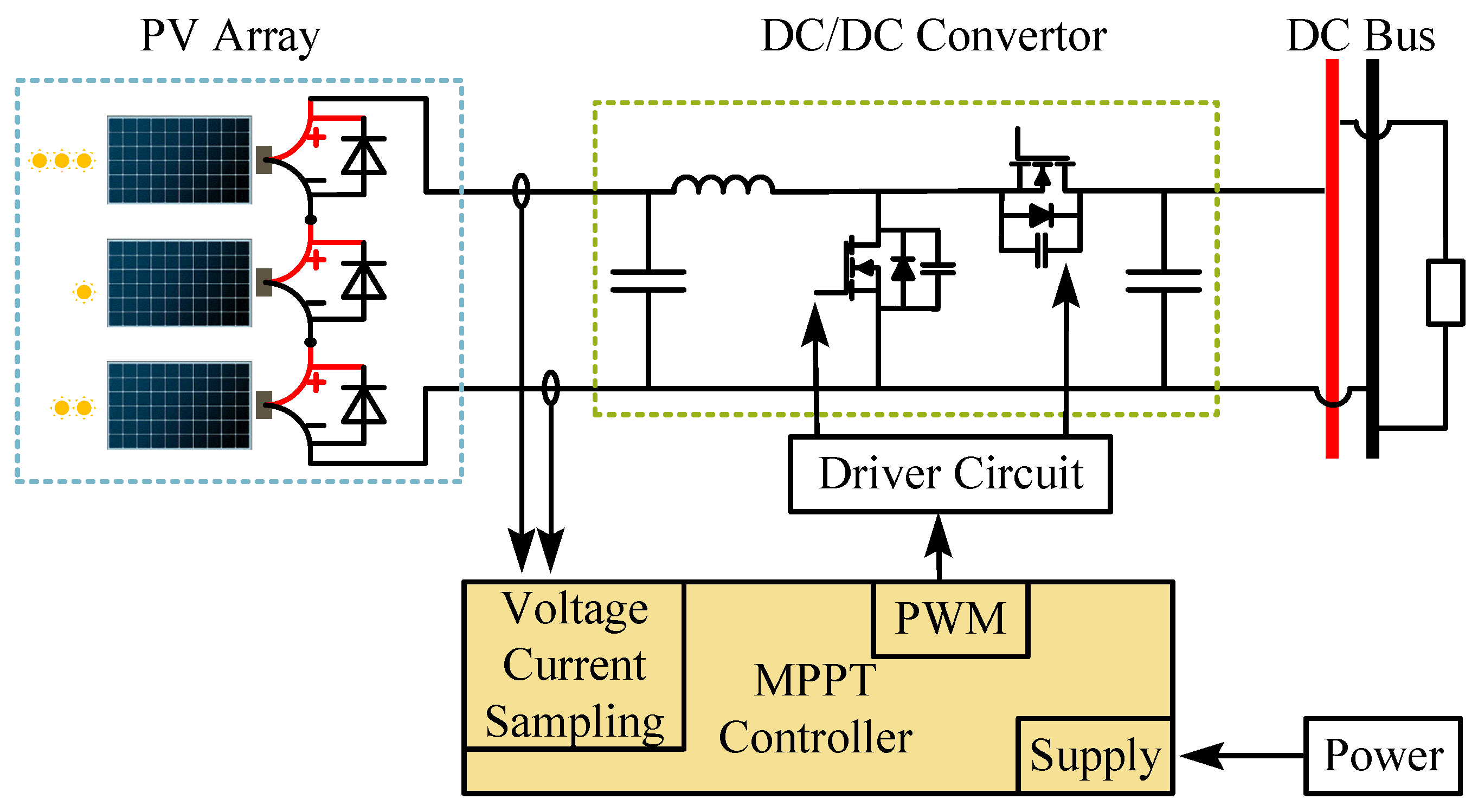
2.1. PV Power Generation System

The mathematical model for engineering a single PV cell [20] is described as follows:
I = I sc 1 C 1 e V C 2 V oc 1 C 1 = 1 I m I sc e V m C 2 V oc C 2 = V m V sc 1 1 ln ( 1 I m I sc )
This model needs only four parameters to describe the characteristics of PV cells with certain accuracy, which is more practical in engineering applications. Voc, Isc, Vm, and Im are open-circuit voltage, short-circuit current, maximum power point voltage, and maximum power point current, respectively.
Changes in temperature and light have different effects on these four parameters, and their change rules are expressed as follows:
I sc = I scref S S ref ( 1 + a Δ T ) V oc = V ocref ln ( e + b Δ S ) ( 1 c Δ T ) I m = I mref S S ref ( 1 + a Δ T ) V m = V mref ln ( e + b Δ S ) ( 1 c Δ T )
where Sref is the reference light intensity with a value of 1000 W/m2, and ∆S is the amount of light intensity change; Tref is the reference ambient temperature with a value of 25 °C, and ∆T is the amount of temperature change; and a, b, and c are the compensation coefficients, whose classical values are 0.0025/°C, 0.0005/(W/m2), and 0.00288/°C, respectively.
The structure of the PV power generation system of the multi-PV module in series is shown in Figure 1, which is connected to the DC bus through the DC/DC converter interface.

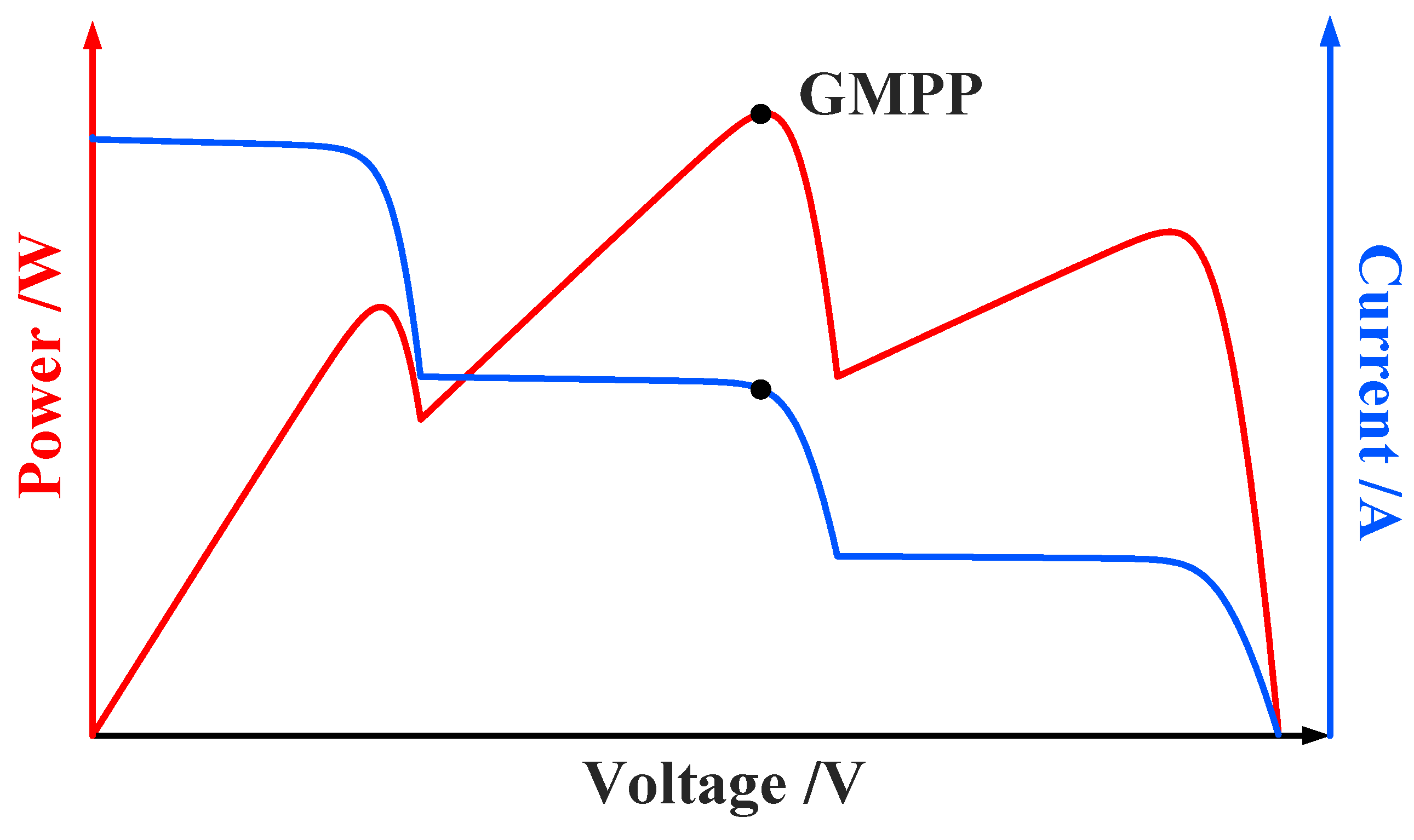
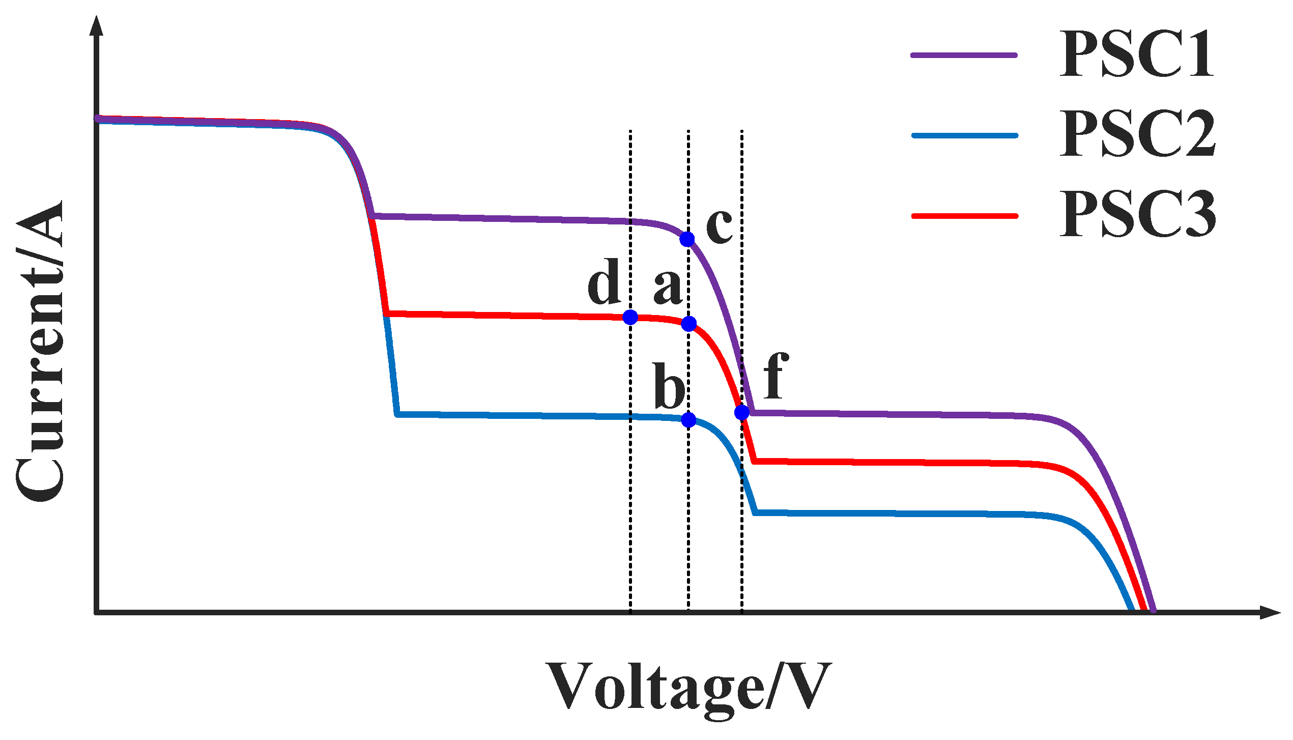
2.2. Analysis of Local Shading Effect

When multiple PV cells are connected in series, if they are locally shaded, their output characteristics will have multiple peaks [21]. The single-peak MPPT algorithm tends to fall into local extremes, resulting in large energy losses. A multi-peak MPPT algorithm that can determine the GMPP and is easy to apply in engineering practice is needed. Figure 2 shows the output P-V and I-V characteristics of three locally shaded PV cells connected in series.
As can be seen from Figure 2, when the PV string is locally shaded, its output characteristics will have multiple peaks, which need to be tracked to the GMPP to maximize the use of PV energy.

3. Proposed Global MPPT Method

3.1. HBA Algorithm Principle

The HBA [13] is modeled after the hunting behavior of the honey badger, which usually has two hunting modes. The first mode is digging, where honey badgers use their sense of smell to locate their prey, and then search for the best digging point around the prey. Its trajectory is similar to a heart-shaped line, the motion of which can be simulated using (4). The second mode is the honey mode, where honey badgers follow a guide bird to directly locate a bee hive, which can be simulated using (5). The initial number of honey badgers is N (the population size), and the initial position is given by (3).
x i = l b i + r 1 × ( u b i l b i )
where ubi and lbi are the upper and lower bounds of the feasible domain, respectively, and r1 is a random number between 0 and 1.
If r2 ≤ 0.5, it is in the mining mode:
x new = x prey + F × β × I × x prey + F × r 3 × α × d i × | cos ( 2 π r 4 ) × [ 1 cos ( 2 π r 5 ) ] |
If r2 ≥ 0.5, it is in the honey-digging mode:
x new = x prey + F × r 6 × α × d i
where xnew is the position of an individual after updating, and xprey is the population optimal solution; β is a constant ≥ 1 (the default is 6), that is, the ability of the honey badger to obtain food; di is the distance from the population optimal solution to the ith honey badger, which can be derived from (6); F is the parameter that changes the direction of the search, which is determined by (7); and r2r7 are six different random numbers between 0 and 1.
d i = x prey x i
F = 1 r 7 > 0.5 1 else
I is the odor intensity (honey attractiveness) determined by (8), where r8 is a random number between 0 and 1; S is the concentration intensity, i.e., the distance from the ith honey badger to the (i + 1)th honey badger.
I = r 8 × S 4 π d i 2 = r 8 × ( x i x i + 1 ) 2 4 π ( x prey x i ) 2
α is the time-varying search factor (density factor) determined by (9), where C is a constant ≥ 1 (the default is 2), and tmax is the maximum number of iterations:
α = C × e t t max

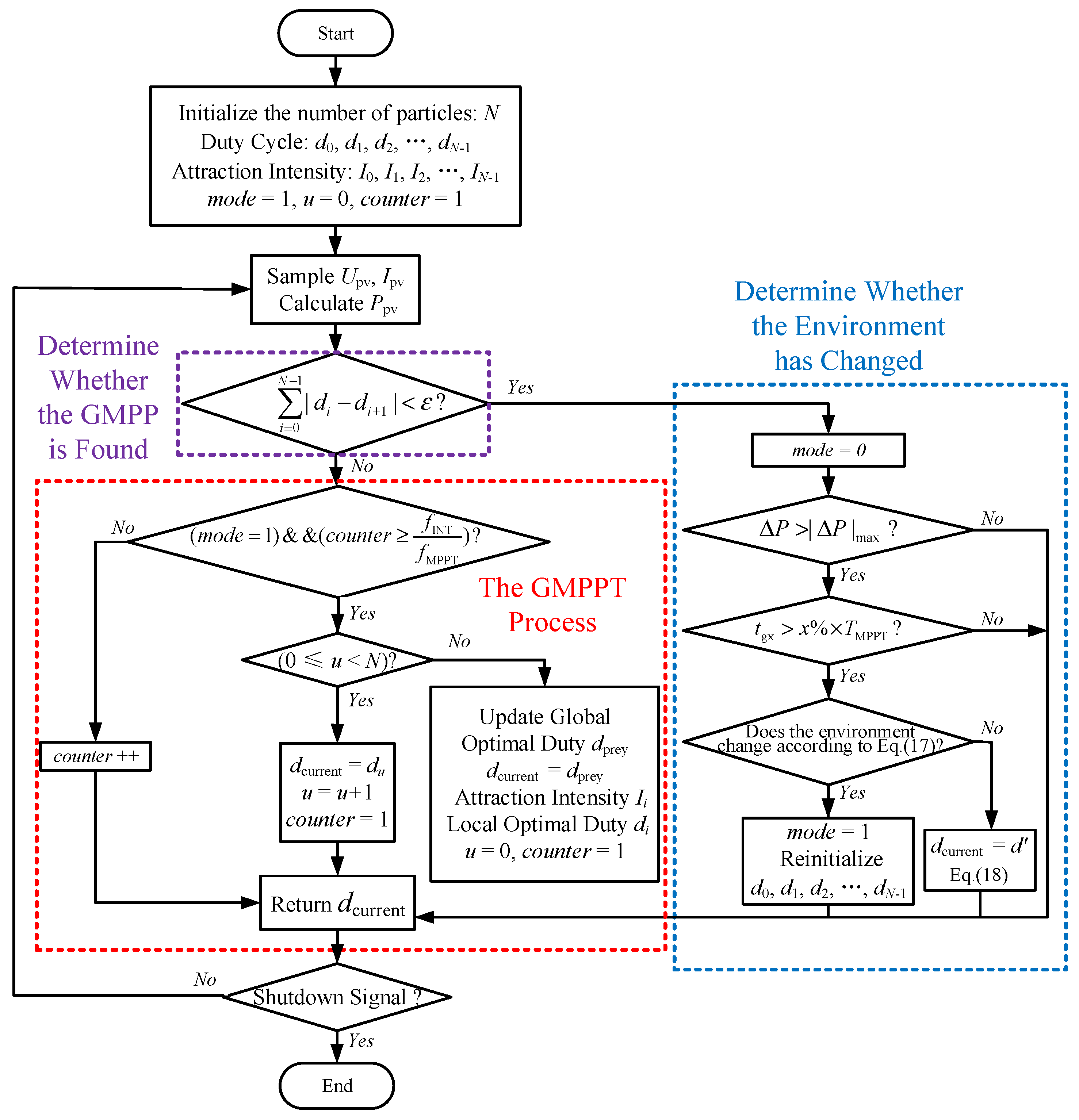
3.2. Multi-Peak PV MPPT Method Based on HBA

The I-V curve of the PV cell output under PSCs are shown in Figure 3. Points a-f denote the operating points on the I-V curve, with a, b, and c being the GMPPs under the three PSCs, respectively. Changing the duty cycle of the DC-DC converter can change the operating point of the PV cell: the larger the duty cycle, the lower the output voltage of the PV cell, and the smaller the duty cycle, the higher the output voltage of the PV cell. The duty cycle and the output voltage of the PV cell are in one-to-one correspondence.
The multi-peak PV MPPT method based on the HBA proposed in this paper needs to sample the current output voltage and current of the PV string, calculate the power corresponding to the current duty cycle with the sampled voltage and current, and record this correspondence. Before the global MPPT, each individual duty cycle di is uniformly initialized by (10), according to the number of particles N and the upper and lower duty cycle limits dmax and dmin. Ref. [22] indicates that the maximum power point voltage of a single photovoltaic module does not exceed 0.9 times the open-circuit voltage. Therefore, the lower limit of the search area, denoted as dmin, can be calculated according to (11). The upper bound of the search area is determined by the maximum gain of the converter. Theoretically, the gain of a boost converter can approach infinity, with the duty cycle nearing 1. However, in practical applications, due to the influence of parasitic parameters, an excessively high duty cycle can severely impair the efficiency of the converter. Hence, considering the output characteristics of photovoltaic cells, the upper limit of the search area is set at 0.8.
d i = d min + ( d max d min ) × ( i + 1 ) N
d min = 1 0.9 × V oc V bus
The proximity between each duty cycle is denoted by ∆dsum, which is derived from (12), and whether the maximum power point has been found is judged by whether ∆dsum is less than a given value ε.
Δ d sum = i = 0 N 1 | d i d i + 1 |
When the HBA is in the digging mode, (13) is used to update the position corresponding to the next duty cycle. When the HBA is in the honey mode, (14) is used to update the position corresponding to the next duty cycle.
d i -new = d prey + F × β × I i × d prey + F × r 3 × α × ( d i d prey )
d i -new = d prey + F × r 3 × α × ( d i d prey )
where di-new is the duty cycle after the update of the ith individual, dprey is the duty cycle corresponding to the current maximum power point, β ≥ 1 is a constant (the default is 6) that is the honey badger’s ability to obtain food, and the directional control parameter F is derived by (7).
The attractiveness of honey Ii can be described as follows:
I i = r 2 × S 4 π ( d prey d i ) 2 + γ = r 2 × ( d i d i + 1 ) 2 4 π ( d prey d i ) 2 + γ
The density factor α is derived by (9), and tmax can be used to limit the maximum tracking time.

3.3. Basis for Determining Changes in the External Environment

The variation in the working point when the high voltage side is connected to the DC bus is shown in Figure 3. Assuming that the current operating point is located at a, if the DC bus voltage changes and the environment remains unchanged, the operating point may change to d or f, Vd < Va < Vf and Id > Ia > If. If the environment changes, the DC bus voltage remains unchanged, and the duty cycle does not change abruptly, the operating point may change to b or c, Vb = Va = Vc and Ib < Ia < Ic. When the DC bus voltage changes result in the operating point shift, the product of the voltage and current changes is negative. The product of the current change is negative. For environmental changes, the product of voltage and current changes is approximately zero.
Using only the amount of change in voltage and current to determine whether the environment has changed may result in misjudgment due to sampling fluctuations, and requires an additional logical judgment. ∆P is a percentage that the current power Pnew deviates from the previous GMPP power PGMPP, as in (16). When ∆P is greater than the upper limit |∆P|max, the calculation of the time tgx for which ∆P is greater than |∆P|max begins. The operating point is considered to have changed if tgx exceeds x% of the MPPT period in one MPPT cycle, as in (17).
Δ P = | P new P GMPP | P gbest × 100 %
t gx > x % × T MPPT
If the change rule of PV voltage and current is in accordance with (18), the working point offset is considered to be caused by the change in bus voltage; otherwise, the working point offset is considered to be caused by the change in environment, where λ is a negative constant. If the work point shift is caused by the bus voltage change, the GMPP position is unchanged, and the new work point of the converter can be derived from (19), where Vbus, V′bus are the voltages before and after the change of the DC bus; and dbus, d′bus are the duty cycle of the converter work point before and after the change of the DC bus. If the operating point shift is caused by an environmental change, the GMPP location is changed and the proposed algorithm is re-run to identify the new maximum power point.
( V V GMPP ) × ( I I GMPP ) < λ
d = 1 ( 1 d ) V bus V bus
The control flow of the multi-peak PV MPPT method based on the HBA is shown in Figure 4, including the parts of algorithm initialization that decide whether to identify the GMPP, global MPPT, or environment change, etc. The algorithm can accurately determine the GMPP of the PV strings in the case of local shading and, due to the higher tracking accuracy and faster convergence, the advantage is more obvious in the case of the large number of PV strings, and a high number of local peak points are more obvious. The method is model-independent and does not require the parameters of individual PVs and the series-parallel relationship between PVs, and it is applicable to PV strings with different parameters if the power and voltage levels are matched.

4. Simulation Results

To guarantee the same sampling time and switching frequency, the proposed method was simulated and compared with PSO [13] and MCA [16]. The simulation results are shown in Figure 5. According to the simulation results, the proposed method has obvious advantages in convergence speed. Moreover, due to the boundary identification, the duty cycle boundary is not exceeded during the iteration process, and the proposed method has the minimum power fluctuation during the convergence process.

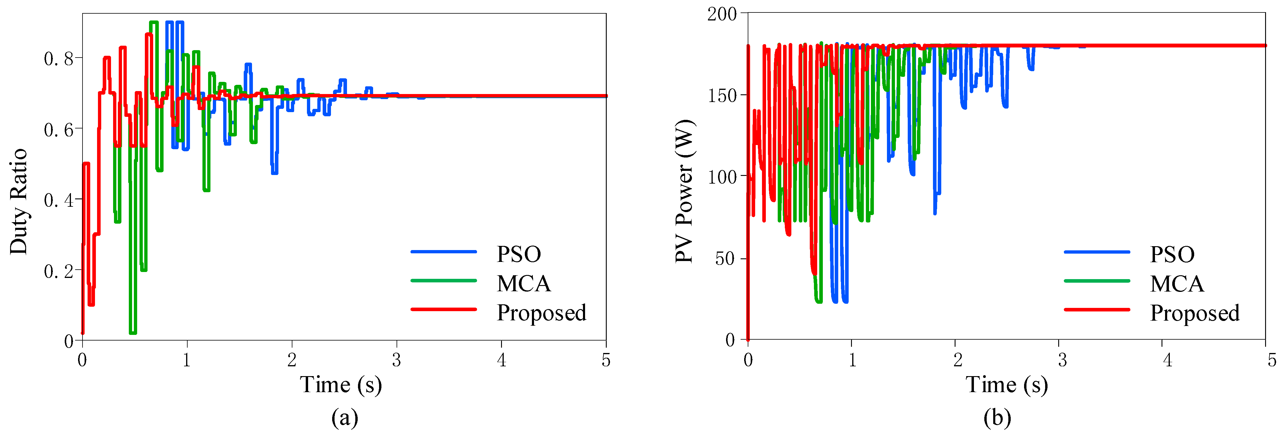
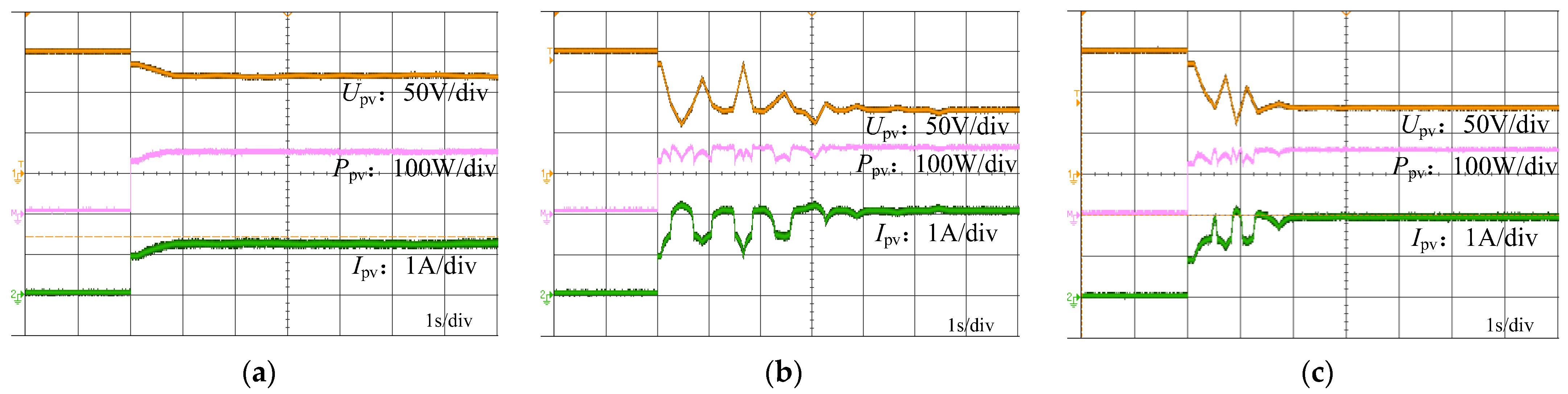
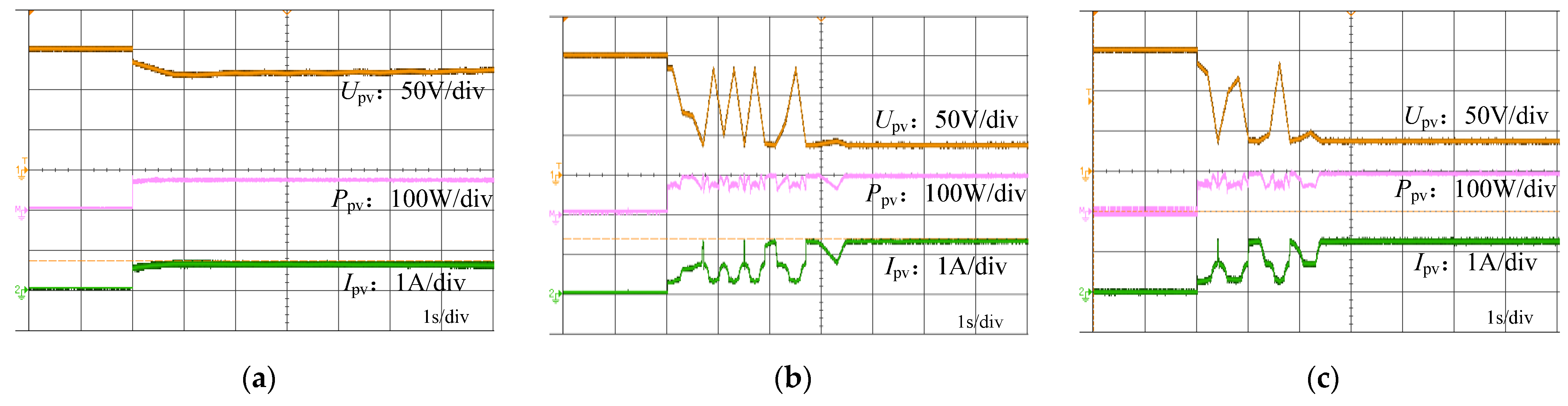
5. Experimental Results and Analysis

The effectiveness of the method proposed in this paper was experimentally verified on a synchronous rectification Boost prototype based on SiC power switching devices. The experimental platform, shown in Figure 6, includes three PV simulators, DC/DC converters, oscilloscopes, and a bidirectional DC power source for simulating the DC bus. The switching frequency of the DC-DC converter was set to 100 kHz. This frequency was determined by considering converter efficiency, output ripple, and system dynamic response speed. The sampling time was set to 0.05 s, which was determined through multiple experiments and performance evaluations. It was based on the dynamic characteristics of the photovoltaic (PV) system and the computational complexity of the algorithm. Since the output power of PV systems typically changes slowly, a sampling time of 0.05 s is sufficient to capture power variations while avoiding excessive computational overhead.

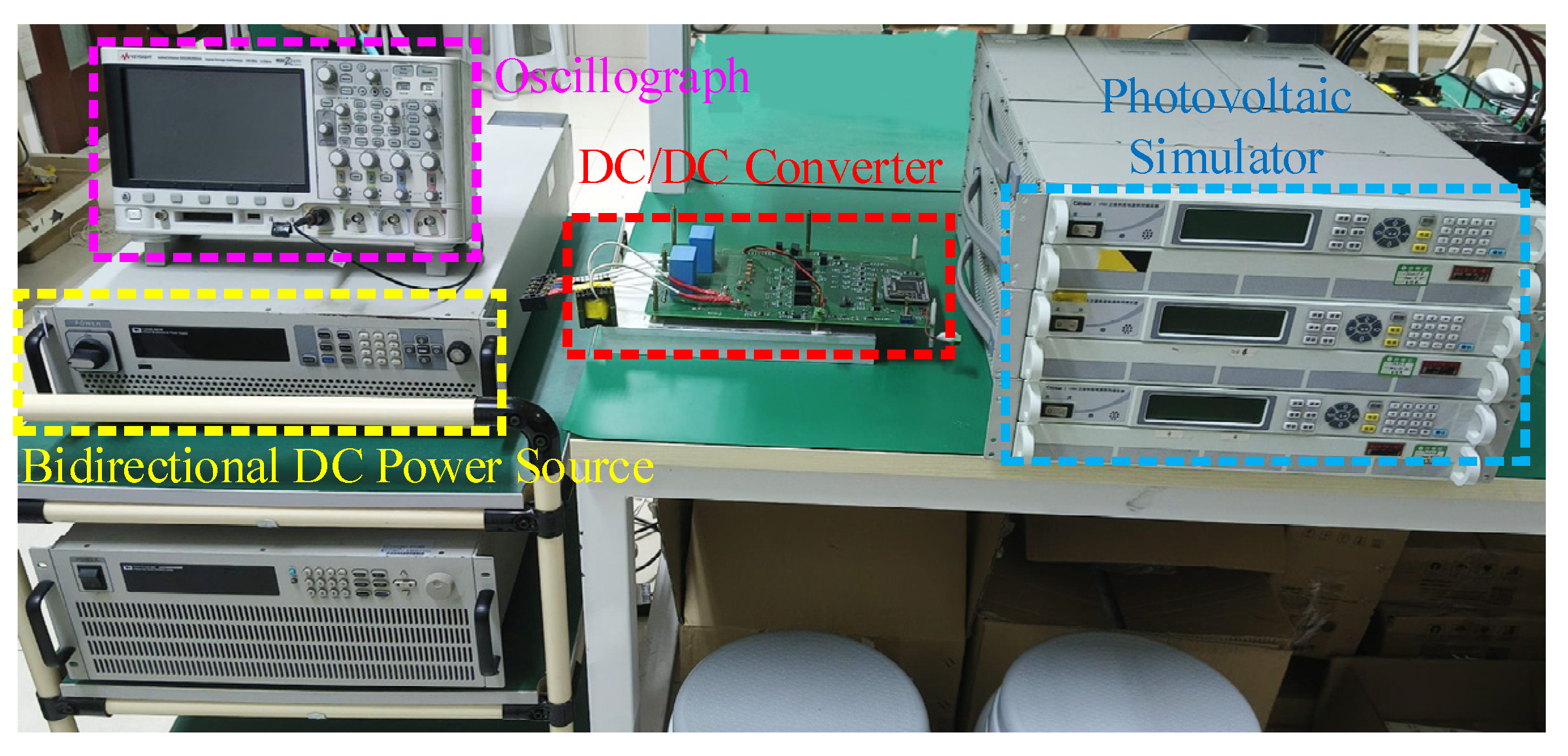
5.1. Experimental Parameters

The number of PV panels in series on the input side was three, and three PV array simulators were used in the experiment. Two localized shading conditions were set up for environmental conditions 1 and 2, and their parameters are shown in Table 2 and Table 3, respectively.
The power–voltage curve of the total output of the three PV panels connected in series under environmental condition 1 is shown in Figure 7, with a GMPP power of 169.25 W. The power–voltage curve of the total output of the three PV panels connected in series under environmental condition 2 is shown in Figure 8, with a GMPP power of 104 W. The MPPT controller is selected as DSP TMS320F28335, and the DC bus voltage is set to 150 V.

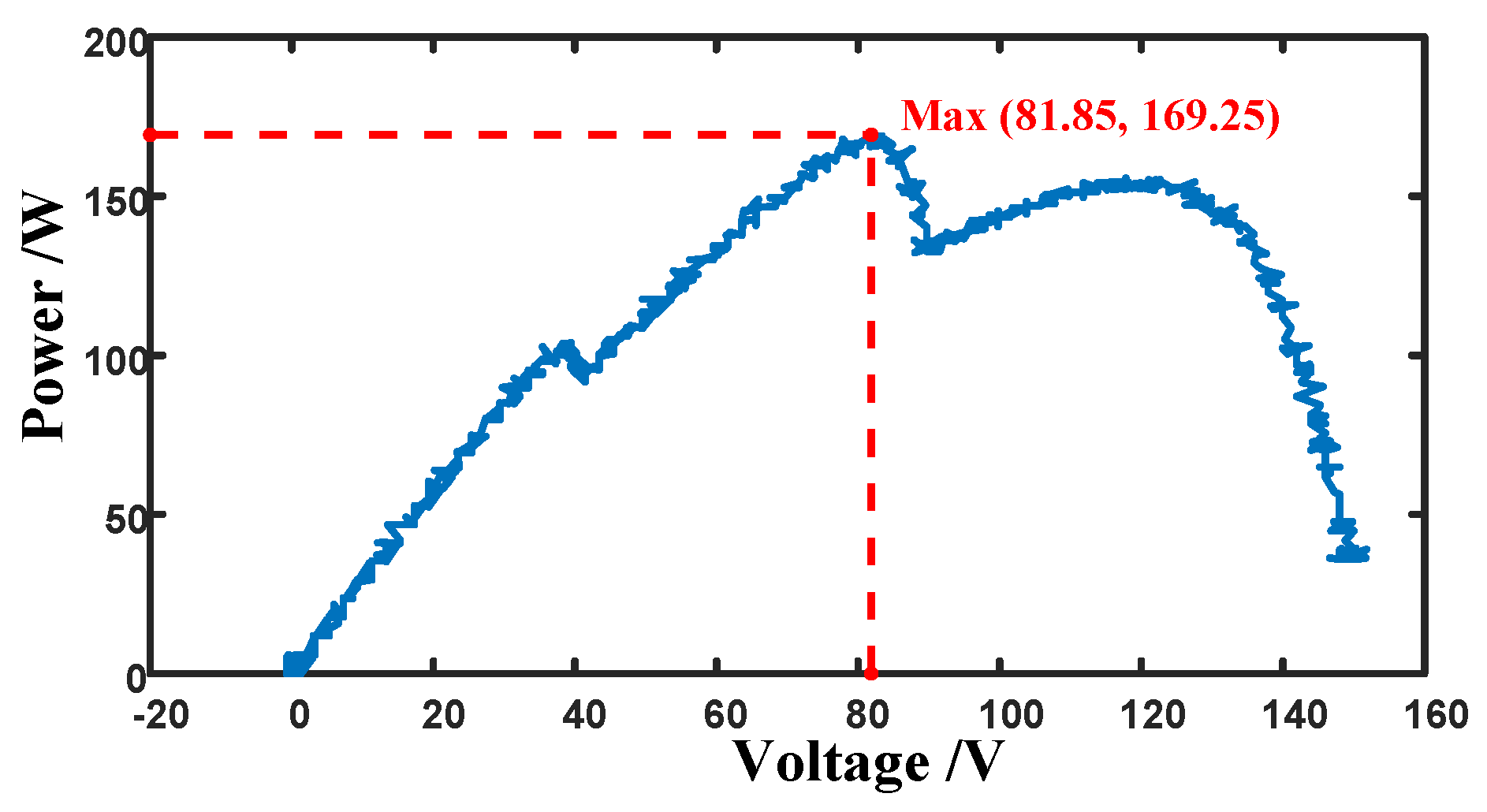
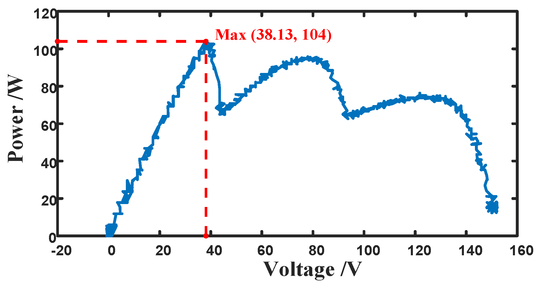
5.2. Experimental Results and Analysis

The power of the GMPP under environmental condition 1 is 169.25 W, corresponding to a voltage of 81.85 V, which is in the middle of the three extreme value points. The other two extreme points correspond to the powers of 104 W and 155.7 W, and the corresponding voltages are 39.45 V and 117.8 V, respectively. The MPPT process of the P&O method, the PSO MPPT method, and the HBA-based MPPT method proposed in this paper under ambient condition 1 for the three methods is shown in Figure 9.
Figure 9a shows the tracking process of the P&O. The tracking time is 0.9 s, the maximum power point power is 154.6 W, and the corresponding voltage is 118 V, which is located at the right extreme point on the power–voltage curve. However, the GMPP has not been determined, and the tracking efficiency is 91.3%. Figure 9b shows the tracking process based on PSO MPPT. The tracking time is 4 s, the maximum power point power is 165 W, and the corresponding voltage is 83.3 V, which is located at the middle extreme point on the power–voltage curve. As a result, the peak where the GMPP is located is identified, and the tracking efficiency is 97.5%. Figure 9c shows the tracking process of the HBA-based MPPT proposed in this paper, with a tracking time of 2 s. The maximum power point power is 166.8 W, corresponding to a voltage of 83 V, which is located in the middle of the pole point on the power–voltage curve. The peak where the GMPP is identified has a tracking efficiency of 98.6%.
The power of the GMPP under environmental condition 2 is 104 W, corresponding to a voltage of 38.13 V, which is located at the leftmost region of the three extreme points. The other two extreme points correspond to powers of 95.84 W and 76.38 W, with corresponding voltages of 77.95 V and 121.9 V. The MPPT process of the three algorithms under environmental condition 2 is shown in Figure 10.
Figure 10a shows the tracking process of the P&O. The tracking time is 0.9 s, the maximum power point power is 75 W, and the corresponding voltage is 121 V, which is located at the right extreme point on the power–voltage curve. However, the GMPP is not determined, and the tracking efficiency is just 72.1%. Figure 10b shows the tracking process based on PSO MPPT. The tracking time is 3.4 s, the maximum power point power is 100 W, and the corresponding voltage is 39.4 V, which is located at the middle extreme point on the power–voltage curve at the peak where the GMPP is located, and the tracking efficiency is 96.2%. Figure 10c shows the tracking process of the HBA-based MPPT proposed in this paper, with a tracking time of 2.4 s. The maximum power point power is 102 W, corresponding to a voltage of 39 V, which is located in the middle extreme point on the power–voltage curve at the peak where the GMPP is located, with a tracking efficiency of 98.1%.
A performance comparison of the three MPPT algorithms under environmental conditions 1 and 2 is shown in Table 4.
When changing from environment condition 1 to 2, the GMPP power changes from 169.25 W to 104 W, and the corresponding voltage changes from 81.85 V to 38.13 V. The peak where the GMPP is located is switched from the centermost point to the leftmost point. The MPPT process of the three algorithms in terms of environment change is shown in Figure 11.
Figure 11a shows the tracking process of the P&O method when the environment changes, and its working point changes from the rightmost peak in Figure 7 to the rightmost peak in Figure 8, which is the local extreme point. The power of both the left and right sides is less than the power of this local extreme point, so the working point does not change during the perturbation process. Figure 11b shows the tracking process of PSO-based MPPT during environmental change, and its operating point changes from the peak in the middle in Figure 7 to the peak in the middle in Figure 8. According to the determination basis of the external environment change, the GMPP changes, and the GMPP is re-searched with a judgment time of 0.2 s and a tracking time of 4.2 s, after which it is stabilized to operate at the GMPP. Figure 11c shows the tracking process of the HBA-based MPPT proposed in this paper when the environment changes, and its operating point changes from the peak in the middle in Figure 7 to the peak in the middle in Figure 8. According to the determination basis of the external environment change, the GMPP changes and the GMPP is re-searched with a judgment time of 0.4 s and a tracking time of 2.8 s, after which it is stabilized to operate at the GMPP.
Through the experimental analysis of three different MPPT algorithms under two environmental conditions, the multi-peak PV MPPT method based on the HBA proposed in this paper can quickly and accurately determine the GMPP under complex shading conditions with fast convergence speed and high tracking accuracy. It is especially applicable when the number of PV strings is large and the number of local peak points is high. It does not depend on the model and does not need the parameters of individual PVs and the series–parallel relationship among PVs, so it is applicable to PV strings with different parameters when the power and voltage levels are matched. It is still effective even if the corresponding converter operating point is close to the maximum gain.

6. Conclusions

Aiming at the multi-peak MPPT problem of the output characteristics of series-connected PV cells under localized shading, this paper proposes a multi-peak PV MPPT method based on the HBA for tracking the GMPP under localized shading environmental conditions. Compared with the MPPT methods based on P&O and PSO, the multi-peak MPPT method based on HBA proposed in this paper has faster tracking speed, higher tracking accuracy, fewer iterations, and the best tracking effect under localized shading conditions. Therefore, the multi-peak MPPT method based on HBA proposed in this paper is more suitable for the MPPT of multi-string PVs under localized shading conditions.

Author Contributions

Conceptualization, Q.G. and L.W.; methodology, Q.G.; software, C.D.; validation, Q.G., L.W. and W.X.; formal analysis, Q.G. and X.L.; writing—original draft preparation, F.Y.; writing—review and editing, H.W.; supervision, H.W. All authors have read and agreed to the published version of the manuscript.

Funding

This research received no external funding.

Data Availability Statement

Data are contained within the article.

Conflicts of Interest

Authors Qianjin Gui, Wenfa Xu, and Xiaoyang Li are employed by State Grid Anqing Electric Power Supply Company. Authors Lei Wang and Chao Ding are employed by State Grid Anhui Electric Power Co., Ltd. The remaining authors declare that the research was conducted in the absence of any commercial or financial relationships that could be construed as a potential conflict of interest.

Abbreviations

The following abbreviations are used in this manuscript:
PSCPartial Shading Conditions
MPPTMaximum Power Point Tracking
HBAHoney Badger Algorithm
P&OPerturbation Observation
PSOParticle Swarm Optimization
PVPhotovoltaic
InCIncremental Conductance
GMPPGlobal Maximum Power Point

References

  1. Chen, J.; Cui, H.; Xu, Y.; Ge, Q. Long-term temperature and sea-level rise stabilization before and beyond 2100: Estimating the additional climate mitigation contribution from China’s recent 2060 carbon neutrality pledge. Environ. Res. Lett. 2021, 16, 074032. [Google Scholar] [CrossRef]
  2. Sher, H.A.; Addoweesh, K.E.; Al-Haddad, K. An efficient and cost-effective hybrid MPPT method for a photovoltaic flyback microinverter. IEEE Trans. Sustain. Energ. 2018, 9, 1137–1144. [Google Scholar] [CrossRef]
  3. Abdulmawjood, K.; Alsadi, S.; Refaat, S.S.; Morsi, W.G. Characteristic study of solar photovoltaic array under different partial shading conditions. IEEE Access 2022, 10, 6856–6866. [Google Scholar] [CrossRef]
  4. Sera, D.; Mathe, L.; Kerekes, T.; Spataru, S.V.; Teodorescu, R. On the perturb-and-observe and incremental conductance MPPT methods for PV systems. IEEE J. Photovolt. 2013, 3, 1070–1078. [Google Scholar] [CrossRef]
  5. Elbarbary, Z.M.S.; Alranini, M.A. Review of maximum power point tracking algorithms of PV system. Front. Eng. Built Environ. 2021, 1, 68–80. [Google Scholar] [CrossRef]
  6. Nadeem, A.; Hussain, A. A comprehensive review of global maximum power point tracking algorithms for photovoltaic systems. Energy Syst. 2021, 14, 293–334. [Google Scholar] [CrossRef]
  7. Allahabadi, S.; Iman-Eini, H.; Farhangi, S. Fast artificial neural network based method for estimation of the global maximum power point in photovoltaic systems. IEEE Trans. Ind. Electron. 2022, 69, 5879–5888. [Google Scholar] [CrossRef]
  8. Xu, S.; Gao, Y.; Zhou, G.; Mao, G. A global maximum power point tracking algorithm for photovoltaic systems under partially shaded conditions using modified maximum power trapezium method. IEEE Trans. Ind. Electron. 2021, 68, 370–380. [Google Scholar] [CrossRef]
  9. Villegas-Mier, C.G.; Rodriguez-Resendiz, J.; Álvarez-Alvarado, J.M.; Rodriguez-Resendiz, H.; Herrera-Navarro, A.M.; Rodríguez-Abreo, O. Artificial neural networks in MPPT algorithms for optimization of photovoltaic power systems: A Review. Micromachines 2021, 12, 1260. [Google Scholar] [CrossRef]
  10. Mobarak, M.H.; Bauman, J. A fast parabolic-assumption algorithm for global MPPT of photovoltaic systems under partial shading conditions. IEEE Trans. Ind. Electron. 2022, 69, 8066–8079. [Google Scholar] [CrossRef]
  11. Shams, I.; Mekhilef, S.; Tey, K.S. Maximum power point tracking using modified butterfly optimization algorithm for partial shading, uniform shading, and fast varying load conditions. IEEE Trans. Power Electron. 2021, 36, 5569–5581. [Google Scholar] [CrossRef]
  12. Javed, S.; Shaque, K.; Siddique, I.A.; Salam, Z. A simple yet fully adaptive PSO algorithm for global peak tracking of photovoltaic array under partial shading conditions. IEEE Trans. Ind. Electron. 2022, 69, 5922–5930. [Google Scholar] [CrossRef]
  13. Kamil, A.; Nasr, M.; Alwash, S. Maximum power point tracking method for photovoltaic system based on enhanced particle swarm optimization algorithm under partial shading condition. Int. J. Intell. Eng. Syst. 2020, 13, 241–254. [Google Scholar] [CrossRef]
  14. Makhloufi, S.; Mekhilef, S. Logarithmic PSO-based global/local maximum power point tracker for partially shaded photovoltaic systems. IEEE J. Emerg. Sel. Top. Power Electron. 2022, 10, 375–386. [Google Scholar] [CrossRef]
  15. Ishaque, K.; Salam, Z. A deterministic particle swarm optimization maximum power point tracker for photovoltaic system under partial shading condition. IEEE Trans. Ind. Electron. 2013, 60, 3195–3206. [Google Scholar] [CrossRef]
  16. Ali, M.E. A novel musical chairs algorithm applied for MPPT of PV systems. Renew. Sust. Energ. Rev. 2021, 146, 111135. [Google Scholar]
  17. Hao, W.; Lin, L.; Haoshen, Y.; Weiwei, Z. Enhancing MPPT efficiency in PV systems under partial shading: A hybrid POA&PO approach for rapid and accurate energy harvesting. Int. J. Elec. Power. 2024, 162, 110260. [Google Scholar]
  18. Ali, M.E. A Novel Strategy for Optimal PSO Control Parameters Determination for PV Energy Systems. Sustainability 2021, 13, 1008. [Google Scholar] [CrossRef]
  19. Hashim, F.A.; Houssein, E.H.; Hussain, K.; Mabrouk, M.S.; Al-Atabany, W. Honey Badger Algorithm: New metaheuristic algorithm for solving optimization problems. Math. Comput. Simul. 2021, 192, 84–110. [Google Scholar] [CrossRef]
  20. Li, Q.; Zhao, S.; Wang, M.; Zou, Z.; Wang, B.; Chen, Q. An improved perturbation and observation maximum power point tracking algorithm based on a PV module four-parameter model for higher efficiency. Appl. Energy 2017, 195, 523–537. [Google Scholar] [CrossRef]
  21. Nandi, A.; Manna, A.; Mohapatra, A.; Saiprakash, C. Analysis of effect of partial shading on PV array and location of local maxima in PV characteristics. In Proceedings of the 2022 2nd International Conference on Power Electronics & IoT Applications in Renewable Energy and its Control (PARC), Mathura, India, 21–22 January 2022. [Google Scholar]
  22. Furtado, A.; Bradaschia, F.; Cavalcanti, M.; Limongi, L.R. A reduced voltage range global maximum power point tracking algorithm for photovoltaic systems under partial shading conditions. IEEE Trans. Ind. Electron. 2018, 65, 3252–3262. [Google Scholar] [CrossRef]
Figure 1. Schematic diagram of multi-panel series PV power generation system.
Energies 18 01258 g001
Figure 2. P-V and I-V curve of output characteristics of series-connected PV strings in localized shading.
Energies 18 01258 g002
Figure 3. Variation of operating point when DC bus is connected to the high-voltage side.
Energies 18 01258 g003
Figure 4. Flow chart of multi-peak PV MPPT control based on HBA.
Energies 18 01258 g004
Figure 5. Simulation waveforms of PSO, MCA, and the proposed method for (a) duty ratio; (b) PV power.
Energies 18 01258 g005
Figure 6. Experimental platform.
Energies 18 01258 g006
Figure 7. Power−voltage curve of PV string output under environmental condition 1.
Energies 18 01258 g007
Figure 8. Power−voltage curve of PV string output under environmental condition 2.
Energies 18 01258 g008
Figure 9. Tracking process of three methods under environmental condition 1. (a) P&O. (b) PSO. (c) HBA.
Energies 18 01258 g009
Figure 10. Tracking process of three methods under environmental condition 2. (a) P&O. (b) PSO. (c) HBA.
Energies 18 01258 g010
Figure 11. Tracking process of three methods when the environment changes. (a) P&O. (b) PSO. (c) HBA.
Energies 18 01258 g011
Table 1. Comprehensive comparison of swarm intelligence algorithm MPPT techniques.
AlgorithmConvergence SpeedTracking EfficiencyOscillations at Steady StateImplementation ComplexityBoundary DetectionCategorization of Power ChangesNo. of Control Parameters
PSO [13]SlowLowLowHighNoNo3
MCA [16]FastHighLowMediumNoNo1
POA&PO [17]FastMediumMediumHighNoNo2
NESTPSO [18]MediumMediumLowHighNoNo3
ProposedFastHighZeroMediumYesYes2
Table 2. Parameters of PV cells in environmental condition 1.
#Uoc (V)Isc (A)Umpp (V)Impp (A)Pmpp (W)Pgmpp (W)
1503.0402.7104
2501.5401.0169.25169.25
3502.3402.0155.7
Table 3. Parameters of PV cells in environmental condition 2.
#Uoc (V)Isc (A)Umpp (V)Impp (A)Pmpp (W)Pgmpp (W)
1503.0402.7104
2501.5401.095.84104
3500.7400.576.38
Table 4. Parameters of proposed MPPT method.
#MethodPmpp (W)Umpp (V)Impp (A)t (s)η (%)
1P&O154.61181.310.991.3
PSO16583.31.98497.5
HBA166.8832.01298.6
2P&O751210.620.972.1
PSO10039.42.543.496.2
HBA102392.622.498.1
Disclaimer/Publisher’s Note: The statements, opinions and data contained in all publications are solely those of the individual author(s) and contributor(s) and not of MDPI and/or the editor(s). MDPI and/or the editor(s) disclaim responsibility for any injury to people or property resulting from any ideas, methods, instructions or products referred to in the content.

