Abstract
This study presents a tailored nitrogen foam flooding system developed for the Mu146 block’s medium-high permeability reservoir conditions. Through systematic optimization, we establish an optimal formulation comprising 0.40% FP2398 foaming agent and 0.13% WP2366 stabilizer. The formulated foam demonstrates superior performance characteristics with a generated volume of 850 mL and extended stability duration of 1390 s, exhibiting exceptional structural integrity under oil-bearing conditions. Core flooding experiments conducted on berea cores reveal a 33.20% incremental oil recovery factor following waterflooding that achieves 53.60% primary recovery. The non-steady-state nitrogen foam huff-and-puff (NSSNFHF) field test at Well Mu146-61 shows significant reservoir response, with post-treatment analyses indicating an average chloride ion concentration increase of 540.20 mg/L and total salinity elevation of 1194.20 mg/L across five monitoring wells. These chemical signatures confirm effective volumetric sweep enhancement through the NSSNFHF field test, demonstrating a flooding-like mechanism that mobilizes bypassed oil in previously unswept zones. The field test encompassing Well Mu146-61 and four offset producers yield substantial production improvements, including a 74.55% increase in fluid production rates and a sustained oil yield of 1.80 tons per day. The validity period of the NSSNFHF field test is more than 12 months. The technology demonstrates dual functionality in conformance control and enhanced recovery, effectively improving both oil productivity and ultimate recovery factors.
1. Introduction
Oil and gas resources remain an important source of energy for social development, but there are still many problems in the development process [1,2,3]. Block Mu146, a medium-high permeability structural reservoir, has reached a water cut of 98.20% and an oil recovery of 50.70% since its commissioning in 1976 [4,5]. Persistent challenges include elevated water–oil ratios, severe ineffective water cycling, suboptimal waterflood utilization, and significant injection–production imbalances. Additionally, while localized residual oil potential remains substantial, recovery enhancement is technically demanding [6,7]. Transitioning development strategies to enlarge sweep volume and enhance displacement efficiency is therefore critical for optimizing reservoir performance [8,9,10,11].
The key mechanism of nitrogen foam huff and puff in production wells is that nitrogen injection can increase reservoir pressure, surfactant injection and polymer injection can control nitrogen flow and reduce oil–water interfacial tension [12,13]. As the nitrogen injection pressure and the soaking time increase, the oil recovery of nitrogen puff and huff increases [14,15]. Bubbles initially form as spheres and expand until they contact the fracture walls, at which point they elongate along the length of the fracture. The rate of bubble growth is influenced by local mass transfer from the liquid phase to the gas phase, as well as gas volume expansion resulting from pressure reduction. The efficiency of the huff-and-puff process is contingent upon the solubility and miscibility of the injected fluid with oil. High gas solubility facilitates increased nucleation, growth, and expansion of bubbles during depressurization cycles [16]. The nitrogen foam huff-and-puff technique presents a viable solution by effectively enhancing sweep coverage, mobilizing trapped oil within fractures or pores, interconnecting with larger fractures that are sealed at their upper ends, reducing residual oil saturation, and improving well productivity [17,18,19]. From a microscopic pore perspective, foam-assisted nitrogen huff-and-puff not only enhances oil production in macropores but also yields a modest amount in micropores and mesopores. Oil recovery from macropores and mesopores significantly contributes to overall recovery factors. The intricate natural fracture structure and its permeability are critical factors influencing oil production in Bakken reservoirs [20,21,22,23].
The presence of fractures significantly influences water cut control and oil recovery in bottom water reservoirs. The application of high-strength starch gel to block these fractures can further enhance the effectiveness of CO2/N2/N2 foam huff-and-puff operations. In the case of pure CO2 huff-and-puff, the primary mechanisms contributing to increased oil production include extraction, viscosity reduction, and the escape of oil droplets. For pure N2 huff-and-puff processes, the expansion of N2 serves as the main driving force for displacing crude oil. When utilizing a gas mixture for huff-and-puff operations at a ratio of 7:3 (CO2 to N2), a synergistic effect between CO2 slugs and N2 slugs is observed, yielding optimal results [24,25,26,27,28]. The drive mechanisms associated with gas cap drive, dissolved gas drive, and miscible drive during CO2 huff-and-puff demonstrate greater efficiency compared to those observed during N2 huff-and-puff processes. Variations in molecular diffusion rates lead to notable changes in oil recovery factors. While simultaneous injection of CO2 and N2 continues to enhance recovery rates, pure CO2 has been shown to yield superior results. In field pilot tests, cost-effective CO2 huff-and-puff processes have been successfully implemented in heavy oil reservoirs characterized by an API gravity as low as 4 °API, reservoir depths reaching up to 1985 m, and pay zones measuring just 12.2 m thick. Specifically, CO2 utilization can be minimized to approximately 4.2 Mscf/Stb. Numerical simulation studies have produced highly accurate results that align well with both experimental data and pilot test findings [29,30]. The foam huff-and-puff mode, characterized by a constant gas injection rate or single slug injection, has proven inadequate in effectively regenerating foam, and its stability is challenging to enhance. Consequently, the effective implementation period on-site remains limited [31,32,33,34].
To address challenges such as low water flooding efficiency, reduced oil production rates, and declining recovery rates during periods characterized by high water cuts in the low-permeability reservoirs of the Mutou Oilfield, non-steady-state (NSS) CO2 huff-and-puff oil recovery technology has been investigated. This NSS CO2 huff-and-puff method demonstrates significant potential for improving development outcomes in low-permeability reservoirs by replenishing reservoir energy and substantially enhancing crude oil mobility. The fundamental mechanisms underlying NSS CO2 huff-and-puff include dissolution, expansion, viscosity reduction, and an increase in swept volume—all effectively mobilizing residual oil from various pore throats within the reservoir. Field trials conducted on NSS CO2 huffed-and-puffed operations within a low-permeability reservoir at Mutou Oilfield have resulted in a cumulative increase in oil production totaling 1134.5 tons. Furthermore, this NSS CO2 injection approach provides valuable insights into nitrogen foam huff-and-puffs testing aimed at promoting effective regeneration and enhanced stability of foam [35].
The alkyl polyglucoside derivatives utilized as foaming agents in foam flooding exhibit superior foaming characteristics. However, a significant issue arises from the fact that alkyl glycoside foaming agents tend to generate white precipitates when used in saltwater containing high concentrations of calcium and magnesium divalent ions. Although the incorporation of an alkyl glycoside sulfonate foaming agent enhances the ability of alkyl glycosides to resist these high levels of calcium and magnesium ions, its elevated production costs hinder its widespread promotion and application in medium-high permeability oil reservoirs [36,37]. Foam stabilizers composed of hydrophobic silica nanoparticles and bentonite have been shown to enhance foam stability by 2–5 times. Nevertheless, a prevailing challenge is the high cost associated with hydrophobic silica nanoparticle foam stabilizers, which limits their on-site promotion and application; additionally, bentonite nanoparticle foam stabilizers are not suitable for use in saltwater with elevated levels of calcium and magnesium divalent ions [38,39]. The engineered foam system demonstrates exceptional plugging characteristics and fluid diversion capabilities, maintaining both its plugging capacity and oil-displacement efficiency even after multiple cycles of dynamic adsorption [40,41].
In order to address the challenges associated with the nitrogen foam huff and puff oil production process, particularly its adverse effects on foam regeneration and stability enhancement, as well as the overall poor stability of the foam system, this study evaluates reservoir adaptability. Well Mu146-61 in Block Mu146 has been selected for field trials involving non-steady-state nitrogen foam huff-and-puff (NSSNFHP). A highly stable foam flooding system with excellent oil tolerance is developed specifically for this application. Core flooding experiments are performed to quantify system displacement efficiency, while systematic monitoring of field performance is undertaken to validate its effectiveness.
2. Experimental Methods
2.1. Materials
The foaming agents (FP series) and foam stabilizers (WP series) are developed by the State Key Laboratory of Enhanced Oil and Gas Recovery and manufactured by the China Petroleum Technology and Development Corporation. Analytical-grade chemicals (Shandong Shengli Oilfield Shengli Chemical Co., Ltd. in Binzhou, China), including sodium bicarbonate, sodium sulfate, sodium carbonate, anhydrous potassium chloride, calcium chloride, and sodium chloride, are used in the experiments. The name and type of foaming agents (FP series) are detailed in Table 1. The name and type of foam stabilizers (WP series) are detailed in Table 2.

Table 1.
Name and type of foaming agents (FP series).
Table 2.
Name and type of foam stabilizers (WP series).
2.2. Produced Water Composition of Well Mu7-18 in Block Mu146
The ionic composition of produced water from Well Mu7-18, with a total salinity of 7610.37 mg/L, is presented in Table 3.
Table 3.
Composition of the formation water.
2.3. Methods
2.3.1. Foam Characterization Methodology
Foam stability assessment is conducted using Q/SY17816-2021-modified protocol with a Waring Blender (waring commercial asslembled Co., Ltd. in Cape Coral, FL, USA) [42]. The experimental procedure comprises three sequential phases:
- (1)
- Aeration: 200 mL surfactant solution is homogenized at 7000 rpm for 60 s under ambient conditions (25 °C, 0.1 MPa).
- (2)
- Foam quantification: Aerated fluid is immediately transferred to a 2000 mL graduated cylinder within 30 s.
- (3)
- Drainage analysis: Initial foam height (V0, mL) and liquid drainage half-life (t1/2, s) are recorded and defined as the time required for 50% liquid separation.
The Foam Composite Index (FCI) is calculated as: (1):
FCI = V0 × t1/2
In the formula: V0—initial foam volume, mL; t1/2—Liquid drainage half-life, s.
2.3.2. Core Flooding Experiment Methodology
The core flooding experiment is performed to assess the oil-displacement efficiency of Formulation 0.40%FP2398 +0.13%WP2366. The high-temperature and high-pressure core oil displacement device is illustrated in Figure 1a. This system enables the simulation of a three-phase multi-component foam flooding process on multi-scale cores under reservoir conditions (temperature: 25~150 °C, pressure: 0 to 70 MPa). Real-time monitoring of pressure distribution is possible, allowing for visual observation of foam morphology and quantitative automatic measurement of oil, gas, and water. Additionally, the mechanisms governing flow in porous media can be investigated. The experimental apparatus employed is depicted in Figure 1b. The components include an injection pump, pressure gauge, surfactant tank, gas tank, oil tank, core holder, confining pump, back pressure pump, gas meter, and produced fluid collector. The cores employed for this test are berea cores. The core sample undergoes the initial drying process in an oven, set to 105 °C, for a duration of 4 h. This is followed by an 8 h vacuuming period, after which it is saturated with formation water to determine both the pore volume (PV) and porosity. The resulting petrophysical properties of the core sample are presented in Table 4. Subsequently, crude oil is introduced into the core holder at a slow injection rate. The core is then aged for a period exceeding 2 weeks following the oil saturation process.
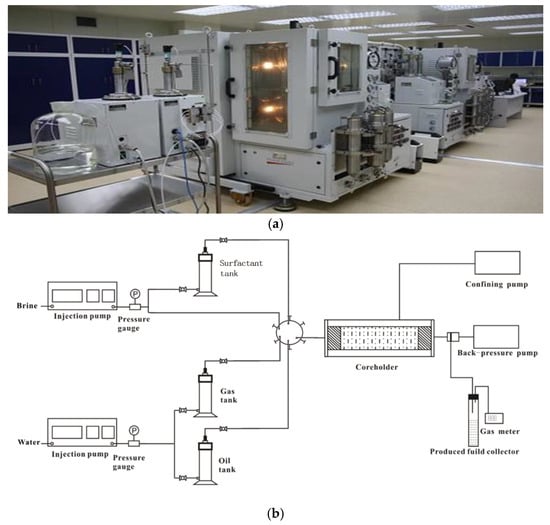
Figure 1.
Core flooding apparatus. (a) High-temperature and high-pressure core flooding devices. (b) Schematic of core flooding apparatus.
Table 4.
Petrophysical properties of core sample.
The core flooding experiment is performed at a consistent temperature of 40 °C, with a backpressure of 8.50 MPa upheld by a backpressure regulator positioned at the core holder’s outlet. Synthetic formation water is introduced at a measured rate of 0.3 mL/min until the cessation of oil production during water flooding. The formulation 0.40%FP2398 + 0.13%WP2366 solution and nitrogen gas are co-injected to generate foam at a total rate of 0.3 mL/min, achieving a foam quality of 75% for 2.00 pore volumes (PV). Subsequently, chase water flooding is performed at an identical injection rate until oil production ceases. To calculate the oil recovery during the test, effluent samples are collected and analyzed.
3. Results and Discussion
The Mu146-61 well in Block Mu146 was put into operation in January 2011, producing F4, 5, and 6 layers with a thickness of 11.8 m. Currently, it produces 12.13 tons of liquid and 0.54 tons of oil per day, with a water cut of 95.6%, an oil pressure of 0.9 MPa, a casing pressure of 0.18 MPa, a dynamic liquid level of 566 m, a cumulative oil production of 2947 tons, and a cumulative liquid production of 80,036 m3.
As the Mu146-61 well is not subject to secondary fracturing, it is characterized by low cumulative production, low production, a narrow south–north sweep range of water drive, a strong water-flooded strip, poor sweep in water drive layer and plane, rich residual potential, and great difficulty in tapping potential. Energy storage and expansion of sweep are urgently needed. NSSNFHF technology can meet geological needs, improve the problem of insufficient formation energy, effectively expand sweep volume, and improve single well productivity. According to the screening criteria for NSSNFHF technology, the reservoir conditions in Block Mu146 are more suitable for NSSNFHF technology, as presented in Table 5.
Table 5.
Application of NSSNFHF technology to reservoir screening indicators.
3.1. Development and Performance Evaluation of Nitrogen Foam Flooding System
3.1.1. Development of Nitrogen Foam Flooding System
Under the condition of reservoir temperature of 40.0 °C and salinity of injected water of 7610.37 mg/L in the Mu146 block, the foaming property and stability of the foam flooding system are evaluated by the Warring stirring method. The self-developed foaming agents FP1688, FP2322, FP2320, FP2332, FP2330, FP2218, FP2268, FP2399, and FP2398 (The main compositions and type are presented in Table 1) are selected for compounding optimization with foam stabilizers WP308, WP100, WP2209, WP131, and WP2366 (The main compositions and type are presented in Table 2). The results are shown in Figure 2 and Figure 3 and Table 6.
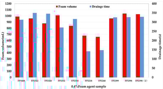
Figure 2.
Evaluation of Foaming Property and Foam Stability of Different Foaming Agents.
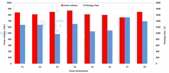
Figure 3.
Evaluation of foaming property and foam stability of foam flooding system. F1: 0.4%FP2398 + 0.10%WP308; F2: 0.4%FP2398 + 0.10%WP100; F3: 0.4%FP2398 + 0.10%WP2209; F4: 0.4%FP2398 + 0.15%WP131; F5: 0.4%FP2398 + 0.10%WP2366; F6: 0.4%FP2398 + 0.12%WP2366; F7: 0.4%FP2398 + 0.15%WP2366; F8: 0.4%FP2398 + 0.13%WP2366.
Table 6.
Evaluation results of oil resistance of foam flooding system.
Based on the foaming agent foaming performance test results (Figure 2), Betaine surfactants FP2218 and FP2268 do not comply with the technical requirements of the Q/SY17816-2021 standard [42], which stipulates a foam volume greater than 800 mL. In contrast, the foam volume and foam stability time of fluorocarbon sulfonate surfactant FP1688 and polyoxyethylene ether sulfonate FP2399 meet the technical specifications outlined in the Q/SY17816-2021 standard [42]; however, it is important to note that these data represent intermediate values. A similar situation applies to olefin sulfonates FP2322, FP2320, FP2332, and FP2330. FP2398 is selected as the foaming agent of the nitrogen foam huff-and-puff test foam oil displacement system, with a foaming volume of 1030 mL and a foam stabilization time of 328 s, which has excellent comprehensive performance. Foaming agent FP2398 is a new, high-foaming, efficient, environmentally friendly, sulfonate-type alcohol ether anionic-nonionic surfactant. Its molecular structure contains sulfonic acid groups and hydroxyl and ether bonds suitable for carbon chains. “Sulfonic acid groups” increase its ability to resist divalent ions, while “hydroxyl and ether bonds suitable for carbon chains” increase its foaming ability and temperature resistance.
In order to improve and strengthen the stability of foam, polymer and other foam stabilizers must be added to the foam flooding system to increase the foam stabilization time. A variety of oil and salt-resistant foam stabilizers have been developed for the reservoir conditions in Block Mu146, including biopolysaccharide polymers, polyacrylamide polymers, and salt-resistant polymers. The self-developed foaming agent FP2398 (0.4% fixed concentration) is selected for compounding optimization with different types and concentrations of foam stabilizers WP308, WP100, WP2209, WP131 and WP2366. As illustrated in Figure 3, under identical apparent viscosity conditions, the type of foam stabilizer exerts minimal influence on the foaming ability of the foam flooding system; however, it significantly affects the stability of the foam within this system. Among the foam stabilizers selected in the experiment, the salt-resistant polymer foam stabilizer WP2366 has the best foam stabilization effect. When the concentration of 0.13% is preferred, it can extend the half-life of the liquid from 328 s to 1390 s and reduce the foaming volume from 1030 mL to 850 mL. In addition, the foaming volume of the foam oil displacement system with 10% oil content is 860 mL, and the half-life of liquid evolution is 1509 s higher than that without oil content, which is 850 mL and 1390 s, respectively, and the oil resistance is excellent (see Table 3). Therefore, WP2366 is selected as the foam stabilizer of the nitrogen foam oil displacement system.
Based on the above experimental results of foaming agent and foam stabilizer optimization, a foam oil displacement system suitable for the NSSNFHP test in the Mu146 block is finally developed as 0.4% FP2398 + 0.13% WP2366.
3.1.2. Berea Core Flooding Experiment
The results of the core flooding experiments are illustrated in Figure 4. The total oil recovery achieved through water flooding is 53.60%, as demonstrated by the pressure gradient and incremental oil recovery observed during foam injection. A robust foam is generated throughout the core, which effectively strips away residual oil trapped within the pores. When foam is formed, the hypertonic channel is blocked, and the injection pressure continues to rise. Furthermore, steady pressure is maintained during chase water flooding, indicating successful propagation of foam within the core’s pore structure, even under these conditions. Foam flooding results in an additional 33.20% incremental oil recovery compared to water flooding, bringing the total oil recovery to 86.80%. When the PV number is greater than 2.53, due to the continuous bursting of the foam, the sealing effect on the hyperosmotic channel is gradually weakened, and the injection pressure also decreases again. Consequently, it can be concluded that the foam formulation exhibited exceptional sweep efficiency, significantly enhancing overall oil recovery.
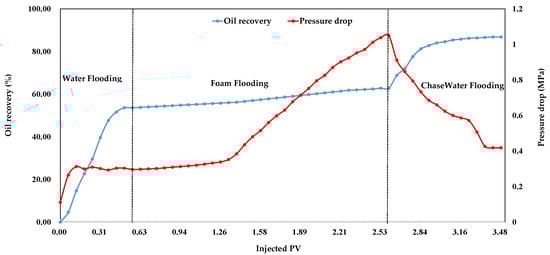
Figure 4.
Oil recovery and pressure drop as a function of injection PV.
3.2. Field Application Effect of Nitrogen Foam Flooding System
3.2.1. Basic Information of Block Mu146
The Block Mu146 is located in the southern part of the Central Depression, within the Huazi Well Terrace of the Muto Structure. The reservoir is a faulted nose structure formed by three faults, with a lithology-structural oil reservoir. The target layers for development are the Fuyu oil layer and the Yangdachengzi oil layer. The Fuyu oil layer primarily consists of deltaic deposits, with the delta plain facies as the dominant feature. The 1st and 2nd sub-layers are delta front facies, and the strata are divided into 17 individual layers. The sandstones of the 4th, 5th, 6th, 7th, 9th, and 10th sub-layers of the Fuyu oil layer are laterally continuous throughout the region, with an average single-layer sandstone thickness of 4.0 to 8.7 m. The III and IV sand groups (8th to 12th sub-layers) produce oil only in the structural high areas of the eastern part of the block, while the structural low areas below the 7th sub-layer are water-bearing. The Yangdachengzi oil layer is developed only in the northern and western parts of the block at local well points. The reservoir depth ranges from 600 to 750 m. This area possesses a substantial oil-bearing zone characterized by significant geological reserves and a reserve abundance of 165.77 (104 t/km2). The average porosity is recorded at 25%, while the average permeability measures 201.8 × 10⁻³ µm2. The initial formation pressure stands at 7.5 MPa, with a saturation pressure of 6.2 MPa. At the surface, the crude oil exhibits a density of 0.882 g/cm3 and a viscosity of 77 mPa·s; conversely, the viscosity for formation crude oil is noted to be 6.8 mPa·s. Additionally, the wax content is quantified at 14.1%, and the pour point is determined to be at 16.2 °C.
3.2.2. Development Status and Existing Problems of Block Mu146
The Block Mu146 has undergone 45 years of waterflood development and rolling adjustments. Based on its development history, it can be divided into four development stages: the initial high production and low water cut stage, the stage of effective waterflooding with high and stable production, the stage of injection and production system adjustments, and the comprehensive adjustment stage. Initially, a diamond-shaped reverse nine-point area water injection well pattern was adopted with a well spacing of 600 m and a well density of 6.1 wells/km2. This was later changed to a linear water injection development method with a 200 m × 100 m spacing. Currently, Block Mu146 comprises a total of 69 oil wells and 46 water wells, yielding daily liquid production rates amounting to approximately 1717 tons alongside daily oil production reaching up to about 42 tons. Presently observed formation pressure has increased to an estimated value of around 8.5 MPa; however, it should be noted that the current oil recovery rate remains low at just about 0.3%. Furthermore, there has been an alarming rise in overall water cut levels, which have now reached 98.2%, coupled with a recovery degree standing at 50.9% and an unfavorable water-to-oil ratio calculated as 7.4. The efficiency regarding water injection practices appears suboptimal due to low utilization rates along with considerable conflicts between injection activities and production outputs being reported within this block’s operations—indicating that it has entered into a phase marked by rapid declines in production accompanied by high or extremely high water cuts.
The eastern part of the Block Mu146 is controlled by a reverse normal fault, with the main productive oil layers being the 4th, 7th, 9th, 10th, and 11th sub-layers. These layers have significant effective thickness, a continuous oil-bearing distribution, and multiple developed sets of strata. The reservoir has high abundance, high initial production, and significant oil and gas accumulation. According to core and saturation data, the remaining oil is widely distributed, with localized accumulations, and there is still considerable potential for further exploitation.
Currently, the Block Mu146 faces prominent development challenges, including severe water washing in the oil layers, significant intra-layer and inter-layer conflicts, imbalanced injection and production profiles, deteriorating sweep efficiency, high water consumption rates in recent years, and serious ineffective water circulation. The overall waterflooding effect is unsatisfactory, making it difficult to further extract remaining oil and stabilize or increase production. Enhancing the recovery rate is also challenging.
In light of these challenges—including the existing development conditions as well as potential demands on this particular oilfield—it becomes imperative to reassess current developmental strategies and methodologies employed therein urgently. Research efforts aimed towards expanding swept volumes while simultaneously enhancing both oil displacement efficiencies and improving overall performance during waterflooding processes will play crucial roles in moving forward toward increasing recovery rates effectively.
3.2.3. NSSNFHP Scheme Design
The Mu146-61 well increases production by adopting the method of non-steady-state nitrogen foam energy-storage huff-and-puff and sweep-efficiency improvement. In the early stage, non-steady-state nitrogen foam is injected for energy storage to raise the formation energy and expand the swept volume. In the later stage, the injected foaming agent enhances the oil-washing ability. Finally, clean water is injected to displace the nitrogen and foaming agent in the wellbore into the interior of the formation, achieving a production increase through huff-and-puff.
Segment Plug Design
The segment plug design of non-steady-state nitrogen foam energy storage, wave adding and efficiency-enhancing huff-and-puff is divided into the following three parts:
- (1)
- NSSNFHP slug: Improve reservoir energy and expand swept volume through non-steady-state N2 foam.
- (2)
- Wash oil plug: Implementing foaming agent systems can significantly reduce interfacial tension associated with crude oils located within near-wellbore zones along deep matrix formations, thereby facilitating improved flow capabilities for said crude oils.
- (3)
- Displace slug: Inject clean water to displace nitrogen in the wellbore and foam agent into the formation.
Injection Parameter Design
- (1)
- The injection volume of non-steady-state nitrogen foam is 1340 m3 (underground volume, with 335 m3 of foaming liquid; 1005 m3 of underground nitrogen, which is equivalent to 73,900 m3 on the ground).
The design of the usage amount of the non-steady-state nitrogen foam system is calculated using the directional method:
Q = π × R2 × H × Φ
In the formula: R—Foam sweep radius (m); H—Effective thickness of the oil layer (m); Φ—Porosity (%)
The effective thickness of the oil layer is measured at 11.8 m, with a porosity of 25%. The radius for foam sweeping has been determined to be 12 m. Calculations indicate that the total volume of the foam system amounts to 1340 m3 (calculated under subsurface conditions), comprising 335 m3 of foaming liquid and 1005 m3 of underground nitrogen. When converted to standard cubic volume at surface conditions, this equates to approximately 73,900 m3.
Calculation of nitrogen conversion coefficient:
Standard state: Temperature is 273.15 K (0 °C), and pressure is 0.1 MPa; Underground state of the Mu146-61 test area in November 2023: Temperature is 313.15 K (40.0 °C), and pressure is 8.43 MPa. The calculated conversion coefficient is 73.53 Nm3/m3, which means 73.53 Nm3 is converted into 1 m3 of underground volume.
- (2)
- The volume of the foaming agent is 44 m3.
- (3)
- The volume of the injected water is 22 m3.
Calculated according to the formula and combined with the geological conditions of this well, the injection volume design is shown in Table 7 (During the construction process, the construction parameters shall be appropriately adjusted according to the pressure change).
Table 7.
Design of usage amount for non-steady-state N₂ foam huff-and-puff in Well Mu 146-61.
- (4)
- To ensure the safety of the wellhead and injection equipment, the anticipated construction pressure will not exceed 80% of the wellhead’s pressure-bearing capacity, which is 20 MPa.
- (5)
- The technical essence of the NSSNFHP test encompasses three core elements: 1. Implementation of a high-emulsification, high-foaming, and ultra-stable foam flooding system; 2. Daily alternating gas–liquid injection cycles with 24 h phase intervals; 3. Slug-stage stepped large-displacement gas injection followed by static diffusion, creating pulsed pressure fluctuations within the reservoir. This operational sequence promotes foam emulsification and high-efficiency regeneration, ultimately forming non-steady-state regenerative nitrogen foam. The resulting process effectively enhances swept volume while improving oil displacement efficiency through optimized foam propagation dynamics. Considering the economic benefits, the construction of this well avoids the peak electricity consumption period. From the 1st to the 13th day, the nitrogen foam huff-and-puff slug is injected. From the 1st to the 5th day, at night, 4860 m3 of nitrogen is injected at an injection rate of 600 m3/h for 8.1 h, and then the injection is stopped for more than 4 h to observe the wellhead pressure. During the day, after the pressure drops, 22 m3 of foaming liquid is injected at an injection rate of 5 m3/h for 4.4 h. From the 6th to the 13th day, at night, 6200 m3 of N2 is injected at an injection rate of 800 m3/h for 7.8 h, and then injection is stopped for more than 4 h to observe the wellhead pressure. During the day, after the pressure drops, 22 m3 of foaming liquid is injected at an injection rate of 5 m3/h for 4.4 h. On the 14th day, 44 m3 of the foaming agent for the oil-washing slug is injected at an injection rate of 5 m3/h for 8.8 h. On the 15th day, 22 m3 of clean water for the displacement slug is injected at an injection rate of 5 m3/h for 4.4 h. During this period, the pressure should be monitored at any time, and the dosage of the foaming agent should be dynamically adjusted according to the pressure change.
Soaking Time Design
The relationship between the pressure drop during soaking and the production increase of a single well has been evaluated in previous tests. When the pressure drop reaches 80% (the ratio of the final pressure after reduction to the pressure at the end of construction) [14], it indicates optimal stimulation effects from these measures. Based on comprehensive analysis, an optimal soaking time is determined to be between 7 to 10 days. During this soaking process, changes in wellbore and reservoir pressures primarily result from gas diffusion; greater pressure drops facilitate better gas diffusion within the reservoir, leading to more effective contact with crude oil.
3.2.4. Evaluation of the Effect of NSSNFHP Test
Injection Situation
The construction, connection of on-site equipment and preparations for injection operations are completed in accordance with the injection process flowchart of the NSSNFHP test in Well Mu146-61 see (Figure 5). Upon completion of injection operations for Well Mu146-61, the casing gas injection pressure was recorded at 13.07 MPa, while foaming liquid injection occurred at a pressure of 6.00 MPa. Consequently, wellhead tubing pressure increased significantly from 0.50 MPa to 5.70 MPa, demonstrating a notable effect on increasing pressure.
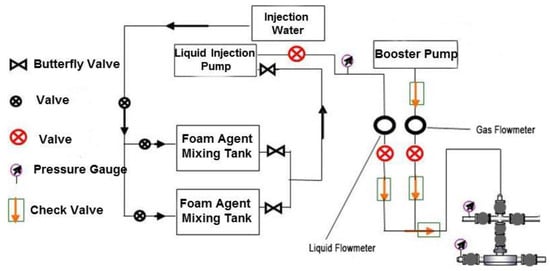
Figure 5.
Injection process flowchart of NSSNFHP test for Well Mu146-61.
Chloride Ion Content
The changes in salinity in the test area before and after the NSSNFHP test in Well Mu146-61 are shown in Table 8. After the NSSNFHP test, the average chloride ion content of five oil wells increased by 540.2 mg/L, and the average total salinity increased by 1194.2 mg/L. This indicates that the NSSNFHP test in this well has expanded the swept volume, mobilized the previously unswept oil-bearing areas, and played a “displacement” role in the oil well drainage [35].
Table 8.
Changes in salinity of the test area before and after the NSSNFHP test in Well Mu146-61.
Test Results
The comprehensive development curve of Well Mu146-61 is shown in Figure 6. The production of the Mu146-61 well group shows the characteristics of “three increases and one decrease”, with obvious oil production increase and a positive trend. Specifically, after the operation, the liquid production increased from 47.38 m3 to 82.70 m3, an increase of 74.55%. In February 2025, the water-cut ratio decreased from 97.64% to 96.46%, while daily oil production rose from 1.12 t to 2.92 t—an increase of 1.80 t (161%). Additionally, the flowing fluid level increased from −242 m to −220 m. For adjacent Well Mu128-64, following operations, daily liquid production escalated from 11.50 m3 to 17.54 m3; concurrently, the water cut reduced from 98.30% to 96.62%. Daily oil production for this well also saw an increase from 0.20 t to 0.60 t in February 2025—a rise of approximately 0.4 t (200%). The flowing fluid level experienced a decline from −83 m down to −266 m.
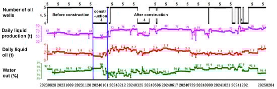
Figure 6.
Comprehensive development curves of Well Mu146-61 and its four adjacent wells.
The validity period of the NSSNFHF field test is more than 12 months. Judging from the on-site sampling on 29 March 2024, the produced fluid was a khaki-colored emulsified oil liquid, which confirmed that the foaming agent has strong emulsifying ability. The NSSNFHP test has expanded the swept volume, mobilized the previously unswept oil-bearing areas, and played a “displacement” role in the adjacent wells of the oil well row (see Figure 7).
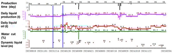
Figure 7.
Production curve of well Mu 128-64.
4. Conclusions
- (1)
- A tailored nitrogen foam flooding system (0.40% FP2398 + 0.13% WP2366) is optimized for the medium-high permeability sandstone reservoirs in Block Mu146. The system exhibits superior performance with a foam volume of 850 mL, foam stability time of 1390 s, and excellent oil tolerance. Berea core flooding experiments demonstrate a 33.20% incremental recovery beyond the baseline waterflood recovery of 53.60%.
- (2)
- A comprehensive NSSNFHP test scheme is designed and implemented for Well Mu146-61. The technical essence of the NSSNFHP test encompasses three core elements:
1. Implementation of a high-emulsification, high-foaming, and ultra-stable foam flooding system.
2. Daily alternating gas–liquid injection cycles with 24-h phase intervals.
3. Slug-stage stepped large-displacement gas injection followed by static diffusion, creating pulsed pressure fluctuations within the reservoir. This operational sequence promotes foam emulsification and high-efficiency regeneration, ultimately forming non-steady-state regenerative nitrogen foam. The resulting process effectively enhances swept volume while improving oil displacement efficiency through optimized foam propagation dynamics.
- (3)
- Post-operation analysis of five producers revealed an average chloride ion concentration increase of 540.20 mg/L and a total salinity rise of 1194.20 mg/L, confirming expanded sweep volume and effective mobilization of previously uncontacted oil-bearing zones. This validates the foam system’s displacement efficacy across the well pattern.
- (4)
- The NSSNFHP test achieved a 74.55% increase in liquid production and 1.80 t/day incremental oil gain in Well Mu146-61 and four offset wells. Water cut control enhances well productivity, demonstrating significant recovery improvement potential. The validity period of the NSSNFHF field test is more than 12 months.
Author Contributions
Conceptualization, Z.-J.W. and X.-Y.Z.; validation, S.-K.L. and X.-H.X.; investigation, J.-Y.L. and B.D.; resources, Q.X. and Z.-F.W.; data curation, Q.X., Z.-F.W., X.-F.W. and J.-R.L.; writing— original draft preparation, J.-Y.L.; writing—review and editing, J.-Y.L., Z.-J.W. and X.-Y.Z.; supervision, B.D. and Q.X.; project administration, Z.-J.W. and X.-H.X.; funding acquisition, X.-Y.Z. All authors have read and agreed to the published version of the manuscript.
Funding
This study is financially supported by the CNPC’s major scientific and technological project: a study on novel mechanisms and techniques for enhancing oil recovery in low permeability and tight reservoirs, project number 2023ZZ0404.
Data Availability Statement
Data are contained within the article.
Acknowledgments
The authors are thankful for the financial support from the CNPC’s Major Scientific And Technological Project: Study of Novel Mechanisms and Techniques for Enhancing Oil Recovery in Low Permeability and Tight Reservoirs, project number 2023ZZ0404.
Conflicts of Interest
The authors declare no conflicts of interest.
References
- Ilyushin, Y.V.; Nosova, V.A. Development of Mathematical Model for Forecasting the Production Rate. Int. J. Eng. Trans. B Appl. 2025, 38, 1749–1757. [Google Scholar] [CrossRef]
- Li, Q.; Li, Q.; Wu, J.; Li, X.; Li, H.; Cheng, Y. Wellhead Stability During Development Process of Hydrate Reservoir in the Northern South China Sea: Evolution and Mechanism. Processes 2025, 13, 40. [Google Scholar] [CrossRef]
- Li, Q.; Li, Q.; Cao, H.; Wu, J.; Wang, F.; Wang, Y. The Crack Propagation Behaviour of CO2 Fracturing Fluid in Unconventional Low Permeability Reservoirs: Factor Analysis and Mechanism Revelation. Processes 2025, 13, 159. [Google Scholar] [CrossRef]
- Tian, D.G. The Fine Structural Interpretation of Quantou Group in Xinmu Area. Master’s Dissertation, Northeast Petroleum University, Daqing, China, 2013. [Google Scholar]
- Li, S.K. Research on the Division and Distribution of Single Sand Bodies in the Fuyu Oil Layer of Block Mu 146 in Mutu Oilfield. In Proceedings of the 8th Jilin Provincial Conference on Science and Technology, Changchun, China, 3–6 August 2024; Jilin Association for Science and Technology: Jilin, China, 2014; Volume 1, pp. 100–101. [Google Scholar]
- Xing, S. Research on Nitrogen Foam Flooding Injection Technology in Mu146 Block of Xinmu Oilfield. Petroleum Knowledg. 2018, 40–41. [Google Scholar]
- Xue, Y.Q. Detailed Reservoir Description for Mu-146 Block. Master’s Dissertation, Northeast Petroleum University, Daqing, China, 2013. [Google Scholar]
- Liao, G.; Yang, H.; Jiang, Y.; Ren, S.; Li, D.; Wang, L.; Wang, Z.; Wang, B.; Liu, W. Applicable Scope of Oxygen-Reduced Air Flooding and the Limit of Oxygen Content. Pet. Explor. Dev. 2018, 45, 111–117. [Google Scholar] [CrossRef]
- Liao, G.Z.; Wang, Q.; Wang, H.Z.; Liu, W.D.; Wang, Z.M. Chemical Flooding Development Status and Prospect. Acta Pet. Sin. 2017, 38, 196–207. [Google Scholar] [CrossRef]
- Fu; Hu, L.Q.; Zhang, F.; Sun, S.S.; Dong; She, Y.H. Research Progress in Mechanismof BioEnzyme Enhanced Oil Recovery. Chem. Bioeng. 2022, 39, 1–7. [Google Scholar]
- Wang, X.R. Study on CO2 and N2 Huff and Puff Parameters of Typical Reservoir in Jidong Oilfield. Master’s Dissertation, China University of Petroleum (East China), Qingdao, China, 2020. [Google Scholar]
- Wang, D.W.; Liao, H.; Ge, T.T.; Du, C.; Cui, Z. Mechanism of Enhanced Oil Recovery by Nitrogen Foam Assisted Steam Huff and Puff. Contemp. Chem. Ind. 2023, 52, 346–349. [Google Scholar] [CrossRef]
- Zhao, F.L.; Fu, Z.F.; Hao, H.D.; Hou, J.; Zhang, M.; Lu, G.; Wang, P. Mechanism of Nitrogen Foam Preventing Edge-water Coning in Huff-and-puff Well. Oilfield Chem. 2018, 35, 451–457. [Google Scholar] [CrossRef]
- Lu, T.; Li, Z.; Li, J.; Hou, D.; Zhang, D. Flow behavior of N2 huf and puf process for enhanced oil recovery in tight oil reservoirs. Sci. Rep. 2017, 7, 15695. [Google Scholar] [CrossRef] [PubMed]
- Fan, Q.; Luo, M.; Bai, Y.; Wang, K.; Pu, C.; Zhan, Y. Experimental and numerical simulation study on enhanced oil recovery by N2-Assisted water huff-and-puff in a tight oil reservoir. Geoenergy Sci. Eng. 2024, 241, 213133. [Google Scholar] [CrossRef]
- Nguyen, P.; Carey, J.W.; Viswanathan, H.S.; Porter, M. Effectiveness of supercritical-CO2 and N2 huff-and-puff methods of enhanced oil recovery in shale fracture networks using microfluidic experiments. Appl. Energy 2018, 230, 160–174. [Google Scholar] [CrossRef]
- Fu, Z.F. Laboratory Research of Nitrogen Foam Preventing Edge-Water Coning in Huff-and-Puff Wells of Nanpu Oilfied. Master’s Dissertation, China University of Petroleum (Beijing), Beijing, China, 2018. [Google Scholar]
- Chen, P.; Zheng, J.L.; Song, Z.X.; Zhang, X.C. A Experimental Research on Nitrogen Foam in Huff Puff Wells Suppressing Edge-bottom Water. Sci. Technol. Eng. 2013, 13, 10147–10149, 10166. [Google Scholar]
- Wang, P.; Zhao, F.L.; Hou, J.R.; Hao, H.; Wang, Z.; Zhang, M. An experimental study of horizontal bottom water coning control with nitrogen foam huff and puff in buried-hill reservoirs. Pet. Geol. Recovery Effic. 2018, 25, 110–115. [Google Scholar] [CrossRef]
- Zhang, J.; Li, Q.; Chen, X.; Lu, G.; Liu, L. Nitrogen Foam Profile Control Improves Steam Huff and Puff Development Effect. In Proceedings of the International Workshop on Environment and Geoscience (IWEG2018), Hangzhou, China, 15–17 June 2018; pp. 223–232, ISBN 978-989-758-342-1. [Google Scholar]
- James, J.; Sheng, T. Optimization of huff-and-puff gas injection in shale oil reservoirs. Petroleum 2017, 3, 431e437. [Google Scholar] [CrossRef]
- Xiong, X.; Sheng, J.J.; Wu, X.; Qin, J. Experimental investigation of foam-assisted N2 huff-and-puff enhanced oil recovery in fractured shale cores. Fuel 2022, 311, 122597. [Google Scholar] [CrossRef]
- Wang, L.; Yu, W. Mechanistic simulation study of gas Puff and Huff process for Bakken tight oil fractured reservoir. Fuel 2019, 239, 1179–1193. [Google Scholar] [CrossRef]
- Wang, P. Experimental Study on Inhibiting Edge or Bottom Water Invasion of N2/CO2/Gas Mixture Huff and Puff. Master’s Dissertation, China University of Petroleum (Beijing), Beijing, China, 2019. [Google Scholar]
- Fu, Z.F.; Zhao, F.L.; Hou, J.R.; Wang, P.; Zhang, M.; Hao, H.; Lu, G. Nitrogen Foam Huff-and-puff Preventing Edge-water Coning for Fault-block Reservoir. Oilfield Chem. 2018, 35, 102–108. [Google Scholar] [CrossRef]
- Wang, D.D.; Ouyang, H.J.; Luan, B.B.; Jiao, W.; Feng, J. Study on exploitation potential of nitrogen foam huff and puff in tight oil reservoirs. China Energy Environ. Prot. 2022, 44, 193–198, 207. [Google Scholar] [CrossRef]
- Wu, X.F. Experimental Study to Prevent Gas Channeling in Huff-and-puff Gas Injection by Foam in Shale Reservoirs. Master’s Dissertation, China University of Petroleum (Beijing), Beijing, China, 2022. [Google Scholar]
- Rong, G.; Li, J.Y. Research Progress of Nitrogen Foam Assisted Steam Huff and Puff in Heavy Oil Reservoirs. Contemp. Chem. Ind. 2021, 50, 2149–2152. [Google Scholar] [CrossRef]
- Li, L.; Su, Y.; Hao, Y.; Zhan, S.; Lv, Y.; Zhao, Q.; Wang, H. A comparative study of CO2 and N2 huff-n-puff EOR performance in shale oil production. J. Pet. Sci. Eng. 2019, 181, 106174. [Google Scholar] [CrossRef]
- Zhou, X.; Yuan, Q.; Peng, X.; Zeng, F.; Zhang, L. A critical review of the CO2 huff ‘n’ puff process for enhanced heavy oil recovery. Fuel 2018, 215, 813–824. [Google Scholar] [CrossRef]
- Chen, S.Y.; Guo, X.D.; He, L.; Shao, G.Y. Feasibility Study on Enhancing Oil Recovery of Clastic Rock Reservoirs in Tahe Oilfield by Nitrogen Foam Huff and Puff Technology. Liaoning Chem. Ind. 2014, 43, 391–394. [Google Scholar]
- Zou, B.; Pu, W.; Zhou, X.; Du, D.; Shi, Y.; Xia, W.; Zeng, F. Experimental Study on the Feasibility of Nitrogen Huff-and-puff in a Heavy Oil Reservoir. Chem. Eng. Res. Des. 2022, 184, 513–523. [Google Scholar] [CrossRef]
- Hao, H.; Hou, J.; Zhao, F.; Huang, H.; Liu, H. N2 -Foam-Assisted CO2 Huff-and-puff Process for Enhanced Oil Recovery in a Heterogeneous Edge-Water Reservoir: Experiments and Pilot Tests. RSC Adv. 2021, 11, 1134–1146. [Google Scholar] [CrossRef] [PubMed]
- Xiong, X.F. Research on Anti-Channeling Effect of Foam in Huff-and-Puff Gas Injection. Ph.D. Dissertation, China University of Petroleum (Beijing), Beijing, China, 2022. [Google Scholar]
- Wang, Z.; Wang, Z.; Luo, W.; Li, S.; Liang, S.; Wang, X.; Xue, X.; Tu, N.; He, S. Research and Application of Non-Steady-State CO2 Huff-and-puff Oil Recovery Technology in High-Water-Cut and Low-Permeability Reservoirs. Processes 2024, 12, 1120. [Google Scholar] [CrossRef]
- Zou, X.Y.; Luo, W.L.; Zhou, X.Y. Synthesis and Application Development of Alkyl Glucoside Derivatives. Appl. Chem. Ind. 2015, 44, 1916–1920. [Google Scholar] [CrossRef]
- Zou, X.Y.; Luo, W.L.; Ma, D.S.; Zhou, X.; Tian, M. Synthesis and Performance of Decyl Polyglycoside Sulfonate for Foam Blended Flooding Agent. China Surfactant Deterg. Cosmet. 2016, 46, 320–323. [Google Scholar] [CrossRef]
- Ru, M.; Chang, Z.D.; Luo, W.L.; Li, W.; Gu, S.; Zhang, Y.; Qiu, H.; Niu, J. Influence of Hydrophobically Modified Silicon Dioxide Particles on Stability of EOR Flooding Foam. CIESC J. 2012, 63, 1943–1950. [Google Scholar] [CrossRef]
- Luo, W.L.; Dang, H.; Zou, X.Y.; Fang, Q.Q.; Li, W.H.; Huang, L.; Liu, Z.X.; Feng, C.Y. Study on the Effect of Bentonite on Foam Stability. Chem. Res. Appl. 2018, 30, 1683–1690. [Google Scholar]
- Luo, W.; Feng, L.; He, C.; Zhou, X.; Jiang, Z.; Luo, Z.; Wang, Z.; Luo, Z. Plugging Characteristics and Flow Redirection Effect of Foam. J. Petrochem. Univ. 2018, 31, 63–68, 89. [Google Scholar] [CrossRef]
- Li, G. Evaluation of Multiple Rounds Dynamic Adsorption, Plugging Performance and Displacement Efficiency of Foam System. Master’s Dissertation, Northeast Petroleum University, Daqing, China, 2017. [Google Scholar]
- Q/SY17816-2021; Specifications of Foaming Agents Used in Foam Flooding. Enterprise Standard of China National Petroleum Corporation Limited. Petroleum Industry Press: Beijing, China, 2021.
Disclaimer/Publisher’s Note: The statements, opinions and data contained in all publications are solely those of the individual author(s) and contributor(s) and not of MDPI and/or the editor(s). MDPI and/or the editor(s) disclaim responsibility for any injury to people or property resulting from any ideas, methods, instructions or products referred to in the content. |
© 2025 by the authors. Licensee MDPI, Basel, Switzerland. This article is an open access article distributed under the terms and conditions of the Creative Commons Attribution (CC BY) license (https://creativecommons.org/licenses/by/4.0/).