

Vacuum-Insulated Glazing Assessment by CFD Modeling and Laboratory Measurements


Abstract
1. Introduction
2. Surface Emissivity Measurements
2.1. Measurement Method—Emissometer
2.2. Measurement Results—Emissometer
3. Numerical Simulations of Thermal Transmittance of VIG
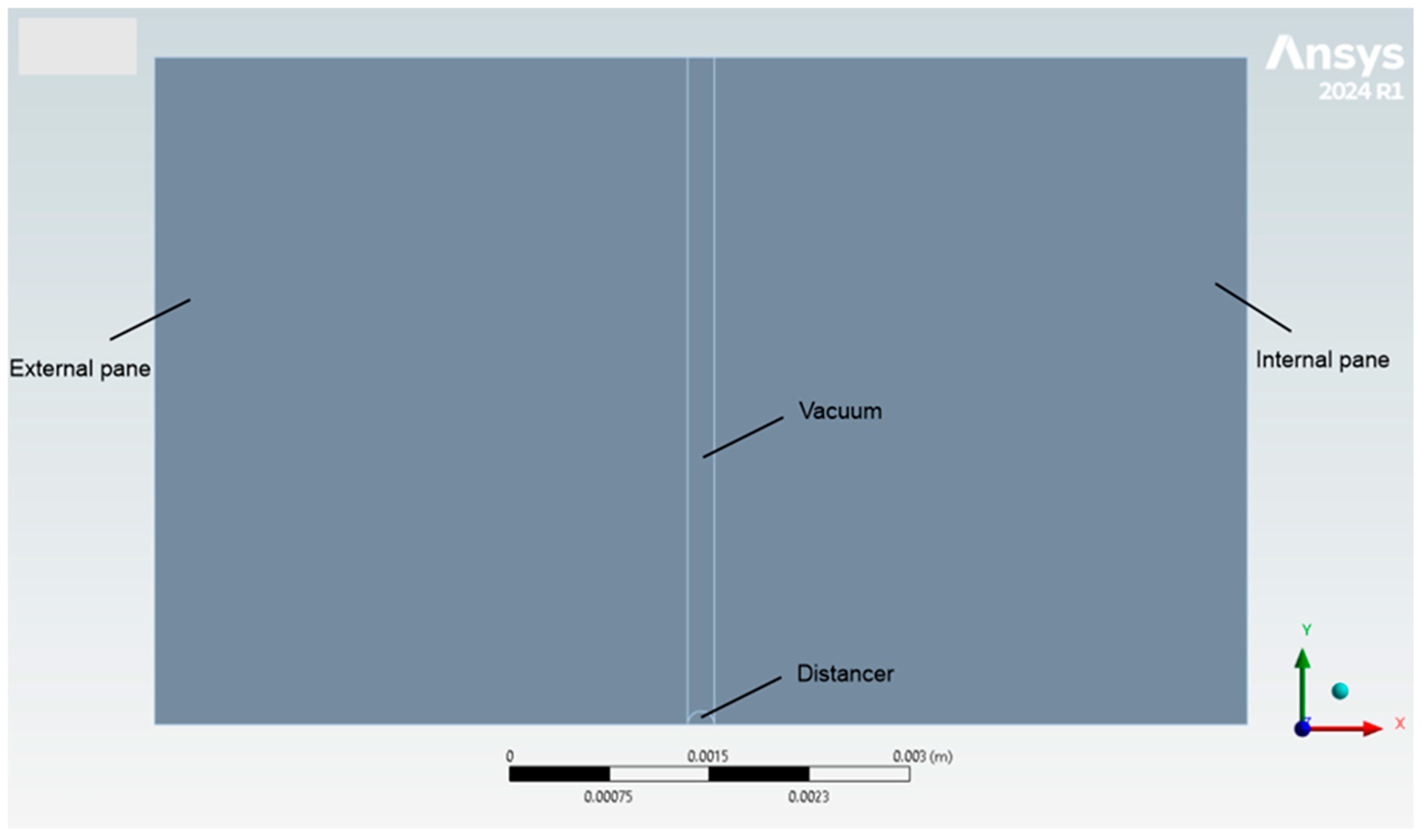
3.1. Method and Description of Calculation Examples
3.2. Numerical Model Settings
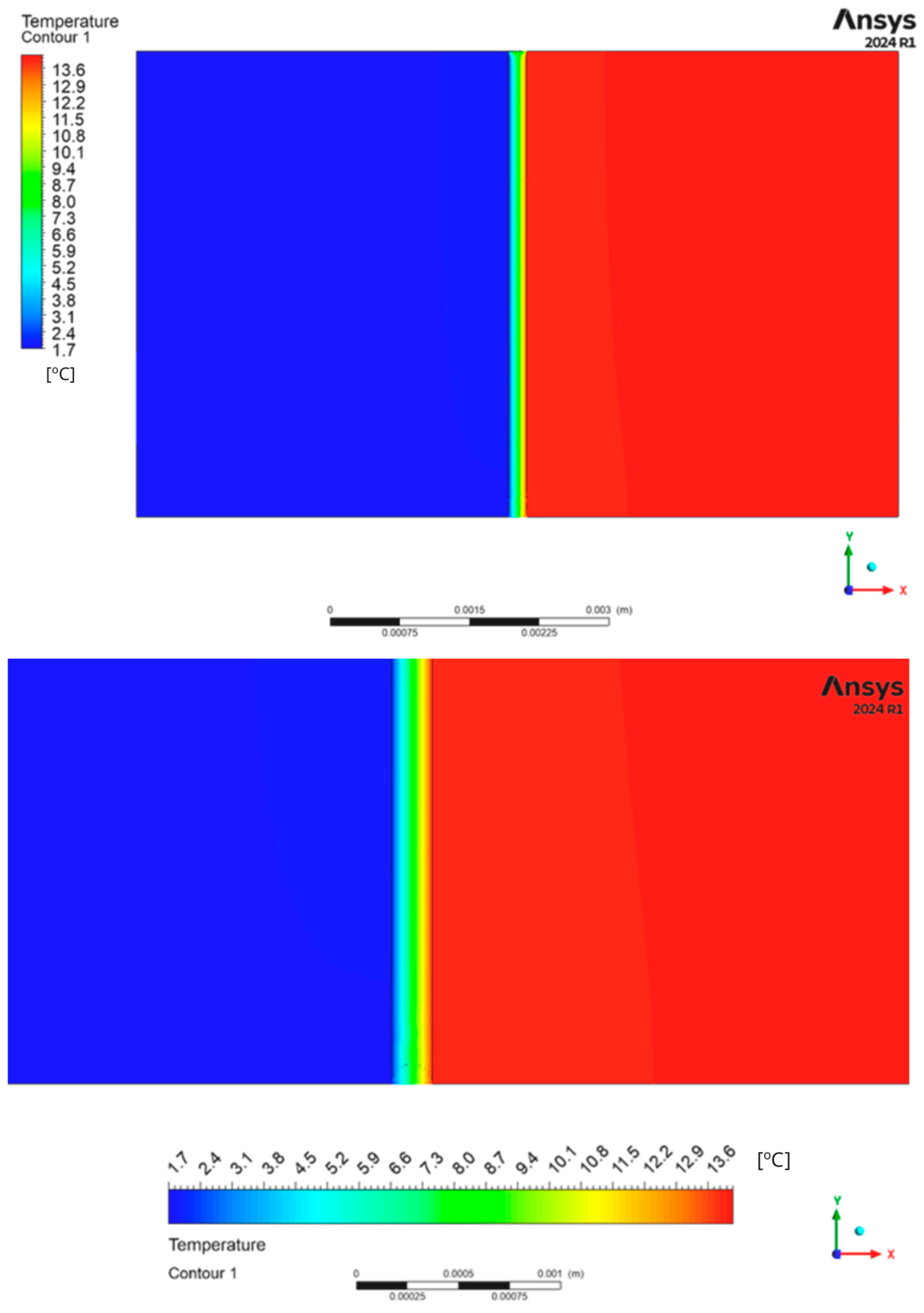
3.3. Numerical Simulation Results
4. Guarded Hot-Plate Measurements of the Vacuum Glazing
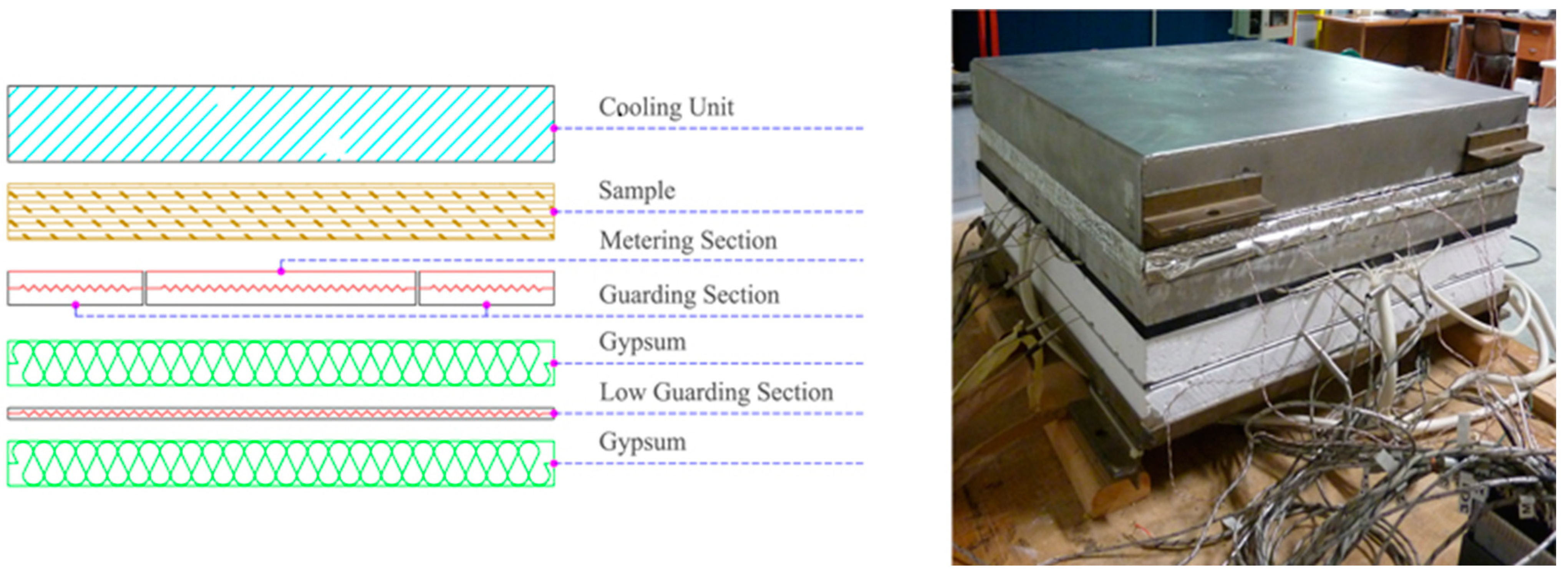
4.1. Measurement Method—Guarded Hot Plate
- -
- 17 thin-wire thermocouples are located within the measurement zone;
- -
- eight thin-wire thermocouples are positioned within the ring guard near its boundary with the measurement zone;
- -
- eight immersion thermocouples are placed within the cooling unit in direct contact with the specimen;
- -
- one shielded thermocouple is inserted within the bottom guard hot plate.
- thermal imbalance monitoring: this group of sensors monitors the temperature difference between the measuring area and the surrounding guard zones;
- average temperature measurement: this group measures the average temperature of both the hot and cold faces of the specimen, enabling the calculation of the average cross-temperature difference.
- -
- Step 1 (sample conditioning): the vacuum glazing is conditioned for 24 h between 105 °C and 110 °C in a climatic chamber for humidity evaporation, as prescribed by Standard EN 12664:2002 [20]. The conditioning is considered effective if the panel weight difference between two conditioning periods is lower than 0.1 kg/m3 or 0.01% by volume.
- -
- Step 2 (thickness measurement): the thickness of the sample is measured on its four sides, and the mean value is registered;
- -
- Step 3 (environmental conditions): the room temperature and relative humidity are registered, fixing them to values close to 20 °C and 50%, respectively;
- -
- Step 4 (panel setup): the lateral edges of the sample are covered with tape, with the aim of preventing humidity from entering the panels themselves;
- -
- Step 5 (pressure set): the upper pressure is set to 3000 Pa;
- -
- Step 6 (temperature set and probes positioning): the hot-plate temperatures are set to 60 °C (hot side) and 15 °C (cold side). Three temperature probes are positioned on both the hot and cold sides of the sample to avoid the influence of any thermal resistance effect linked to the contact with the hot and cold plates. The average values of the three thermocouples for each side, Th and Tc, are used for this calculation;
- -
- Step 7 (measurement): the thermal conductivity is retrieved according to the following equation:
4.2. Measurement Results—Guarded Hot Plate
5. Calorimetric Chamber Measurements of the Vacuum Glazing
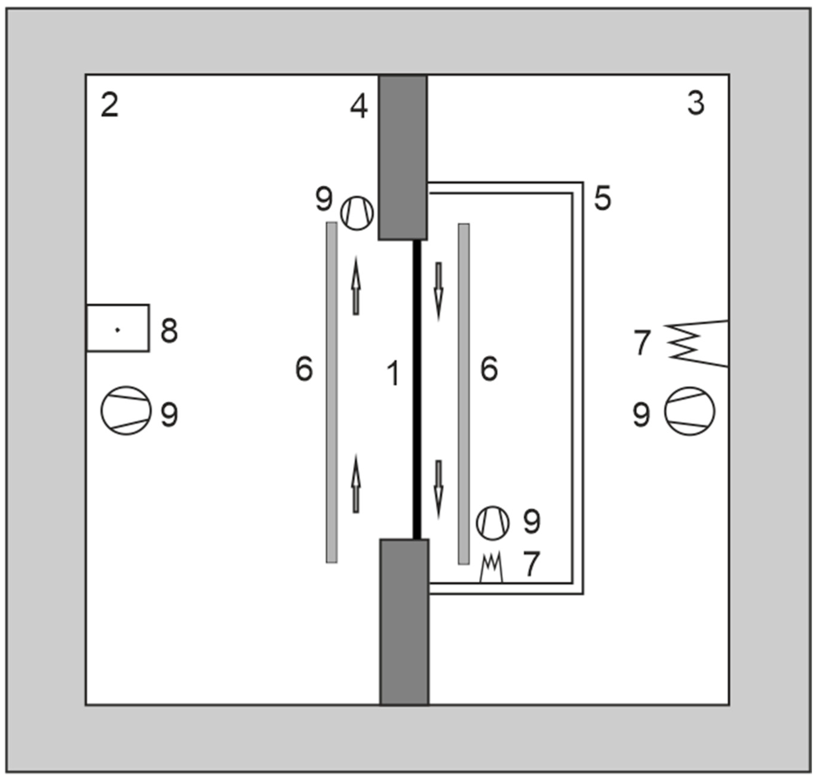
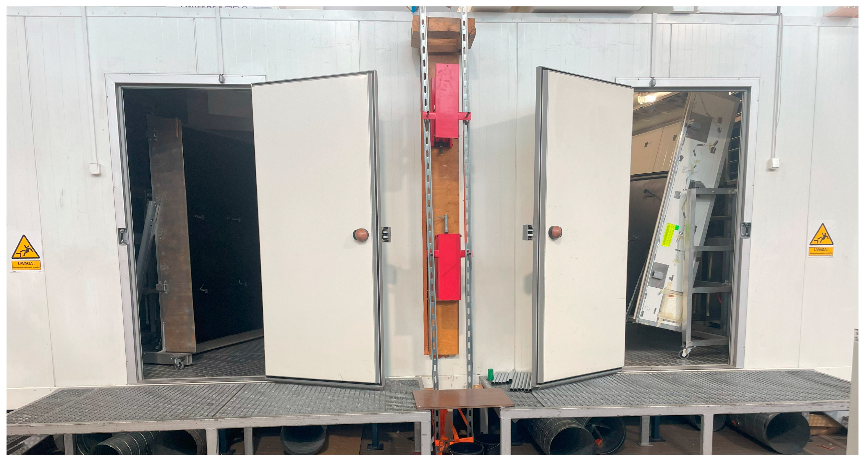
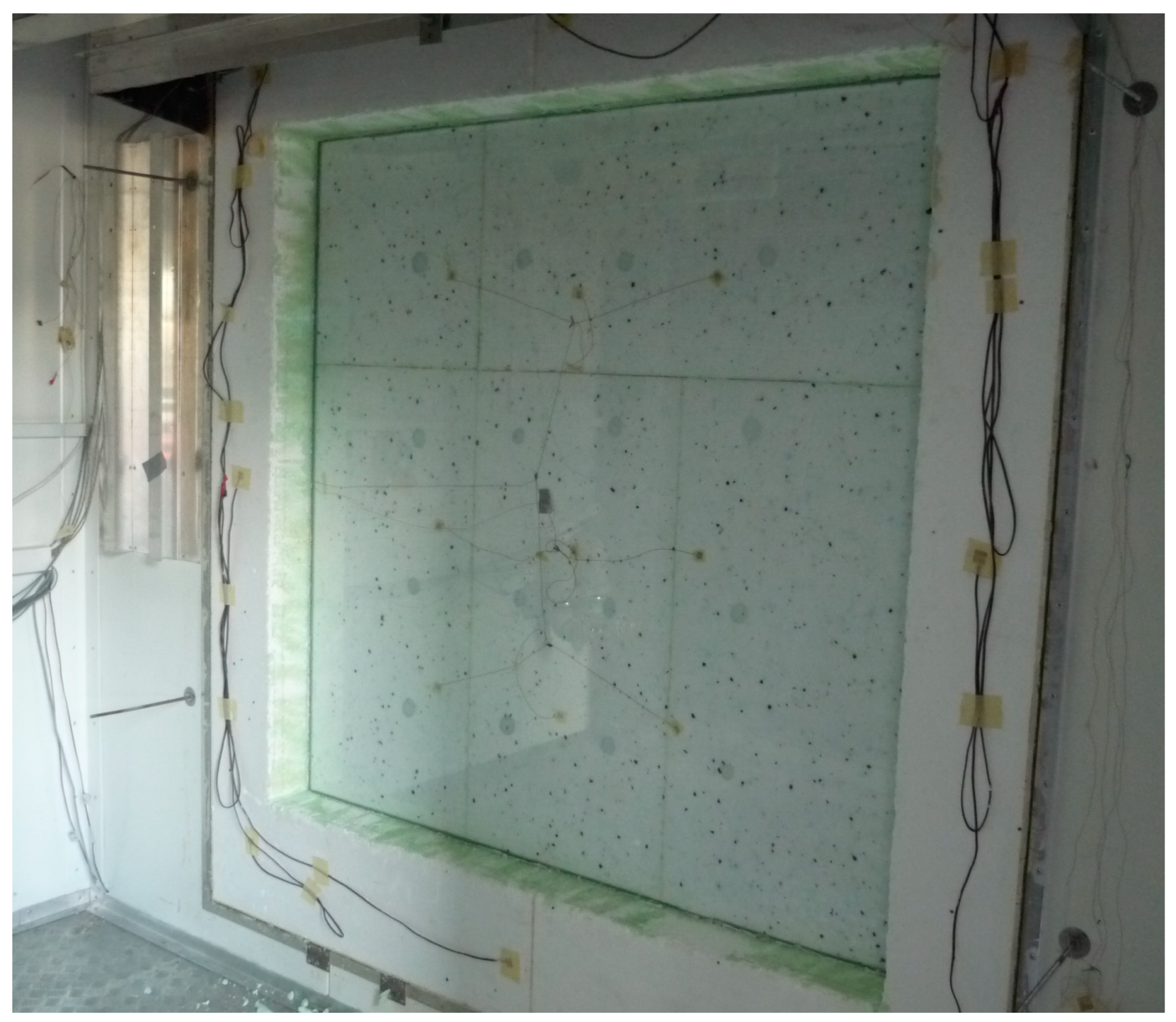
5.1. Measurement Method—Calorimetric Chamber
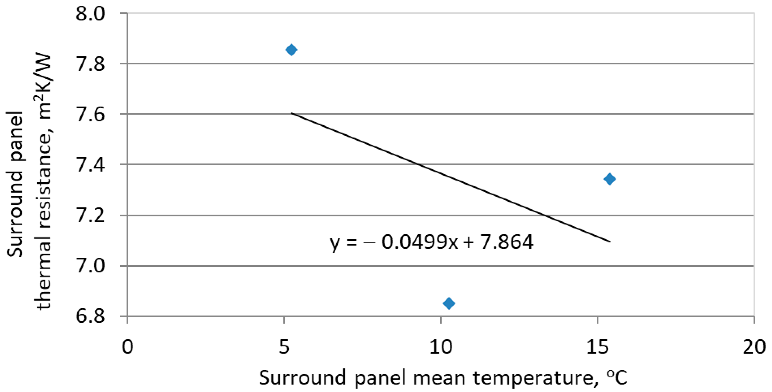
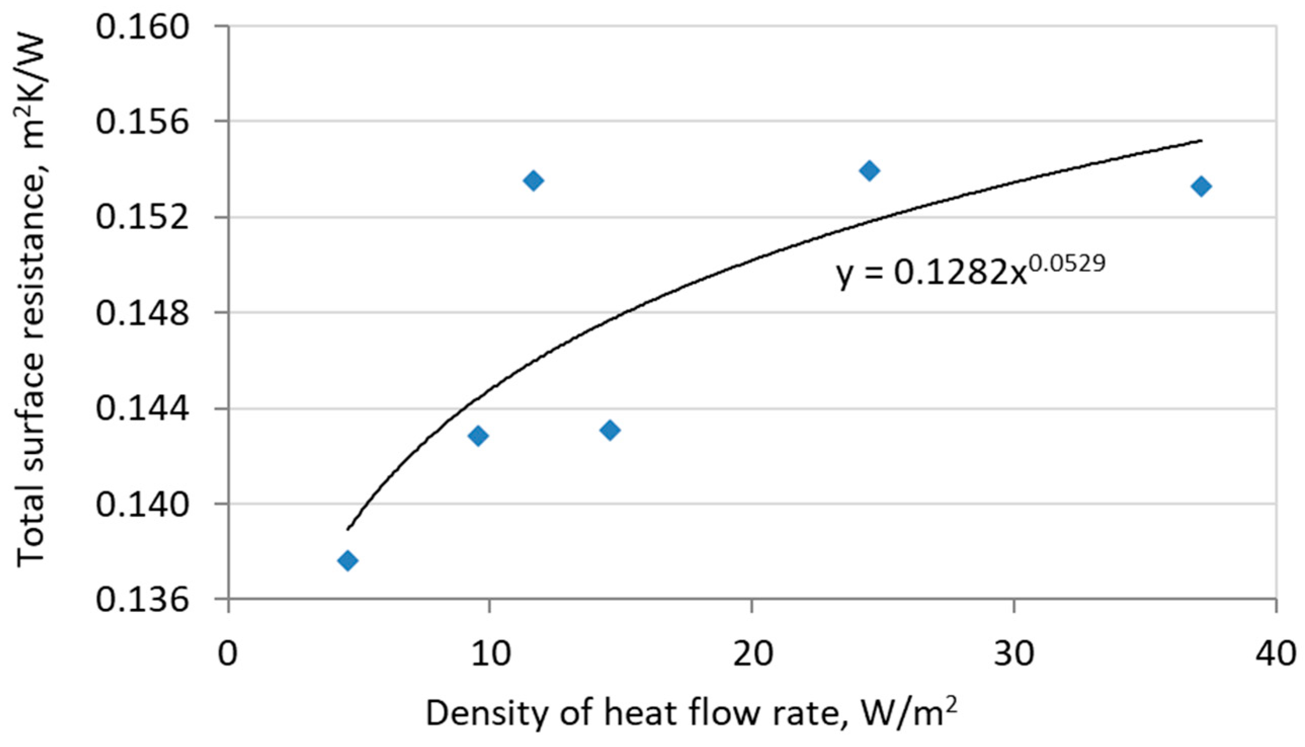
5.2. Calibration Panel Measurement Results—Calorimetric Chamber
5.3. Tested Sample Measurement Results—Calorimetric Chamber
6. Summary and Conclusions
Author Contributions
Funding
Data Availability Statement
Acknowledgments
Conflicts of Interest
Abbreviations
| VIG | Vacuum-Insulated Glazing |
| PID | Proportional–Integral–Derivative |
| DAQ | Data Acquisition |
| LD | Linear dichroism |
References
- Zhu, W.; Zhang, S.; Shin, S.; Gorti, S.; Shah, B.; Joshi, P.; Bhandari, M. Effects of Pillar Design on the Thermal Performance of Vacuum-Insulated Glazing. Constr. Build. Mater. 2022, 316, 125724. [Google Scholar] [CrossRef]
- Cuce, E.; Cuce, P.M. Vacuum Glazing for Highly Insulating Windows: Recent Developments and Future Prospects. Renew. Sustain. Energy Rev. 2016, 54, 1345–1357. [Google Scholar] [CrossRef]
- Peng, J.; Tan, Y.; Fang, Y.; Yang, H.; Song, A.; Curcija, C.; Selkowitz, S. Excellent Insulation Vacuum Glazing for Low-Carbon Buildings: Fabrication, Modeling, and Evaluation. Engineering 2024, in press. [Google Scholar] [CrossRef]
- Kim, S.C.; Yoon, J.H.; Lee, R.D. Energy Performance Assessment of a 2nd-Generation Vacuum Double Glazing Depending on Vacuum Layer Position and Building Type in South Korea. Energies 2017, 10, 1240. [Google Scholar] [CrossRef]
- Zhao, J.F.; Eames, P.C.; Hyde, T.J.; Fang, Y.; Wang, J. A Modified Pump-Out Technique Used for Fabrication of Low Temperature Metal Sealed Vacuum Glazing. Sol. Energy 2007, 81, 1072–1077. [Google Scholar] [CrossRef]
- Griffiths, P.W.; Eames, P.C.; Hyde, T.J.; Fang, Y.; Norton, B. Experimental Characterization and Detailed Performance Prediction of a Vacuum Glazing System Fabricated with a Low Temperature Metal Edge Seal, Using a Validated Computer Model. J. Sol. Energy Eng. 2006, 128, 199–203. [Google Scholar] [CrossRef]
- Memon, S.; Fang, Y.; Eames, P.C. The Influence of Low-Temperature Surface Induction on Evacuation, Pump-Out Hole Sealing and Thermal Performance of Composite Edge-Sealed Vacuum Insulated Glazing. Renew. Energy 2019, 135, 450–464. [Google Scholar] [CrossRef]
- Bao, M.; Liu, X.; Yang, J.; Bao, Y. Novel Hybrid Vacuum/Triple Glazing Units With Pressure Equalisation Design. Constr. Build. Mater. 2014, 73, 645–651. [Google Scholar] [CrossRef]
- Riedel, H.; Mokdad, S.; Schulz, I.; Kocer, C.; Rosendahl, P.L.; Schneider, J.; Kraus, M.A.; Drass, M. Automated Quality Control of Vacuum Insulated Glazing by Convolutional Neural Network Image Classification. Autom. Constr. 2022, 135, 104144. [Google Scholar] [CrossRef]
- Zhu, W.; Shah, B.; Gorti, S.; Bhandari, M.; Sabau, A.S.; Shin, S. Effects of Edge Seal Design on the Mechanical and Thermal Performance of Vacuum-Insulated Glazing. Build. Environ. 2022, 224, 109572. [Google Scholar] [CrossRef]
- Chuntonov, K.; Ivanov, A.O.; Verbitsky, B.; Setina, J. Getters for Vacuum Insulated Glazing. Vacuum 2018, 155, 300–3006. [Google Scholar] [CrossRef]
- Tiwari, R.; Kim, J. Multi-Cell, Triple Pane, Vacuum Insulated Glazing. Sol. Energy 2022, 245, 340–352. [Google Scholar] [CrossRef]
- International Standard EN 673:2011; Glass in Building—Determination of Thermal Transmittance (U Value)—Calculation Method. German Institute for Standardization: Berlin, Germany, 2011.
- ASTM C1371-04a (2010) e1; Standard Test Method For Determination of Emittance of Materials Near Room Temperature Using Portable Emissometers. ASTM International: West Conshohocken, PA, USA, 2010.
- Ng, N.; Collins, R.E.; So, L. Characterization of the Thermal Insulating Properties of Vacuum Glazing. Mater. Sci. Eng. B 2007, 138, 128–134. [Google Scholar] [CrossRef]
- International Standard EN ISO 10077-2:2017; Thermal Performance of Windows, Doors and Shutters—Calculation of Thermal Transmittance—Part 2: Numerical Method for Frames. ISO: Geneva, Switzerland, 2017.
- Lechowska, A.A.; Schnotale, J.A.; Baldinelli, G. Window Frame Thermal Transmittance Improvements Without Frame Geometry Variations: An Experimentally Validated CFD Analysis. Energy Build. 2017, 145, 188–199. [Google Scholar] [CrossRef]
- Lechowska, A.A. A CFD Study and Measurements of Double Glazing Thermal Transmittance Under Downward Heat Flow Conditions. Energy Build. 2016, 122, 107–119. [Google Scholar] [CrossRef]
- Ansys Fluent User’s Guide. Available online: https://www.afs.enea.it/project/neptunius/docs/fluent/html/ug/main_pre.htm (accessed on 20 December 2024).
- International Standard EN 12664:2001; Thermal Performance of Building Materials and Products—Determination of Thermal Resistance by Means of Guarded Hot Plate and Heat Flow Meter Methods—Dry and Moist Products of Medium and Low Thermal Resistance. British Standards Institution: London, UK, 2001.
- International Standard EN ISO 8990:1998; Thermal Insulation—Determination of Steady-State Thermal Transmission Properties—Calibrated and Guarded Hot Box. ISO: Geneva, Switzerland, 1998.
- International Standard EN ISO 12567-1:2010; Thermal Performance of Windows and Doors—Determination of Thermal Transmittance by the Hot-Box Method—Part 1: Complete Windows and Doors. ISO: Geneva, Switzerland, 2010.


| Solver | Stationary | |
|---|---|---|
| Discretization scheme | Energy | Second order upwind |
| Radiation model | Discrete Transfer Radiation Model (DTRM) for diffuse surfaces with ray tracing—all pane surfaces are radiating surfaces with given emissivity—the “ray tracing” technique can predict radiative heat transfer between surfaces without view factor calculations. | |
| Relaxation factor for energy | 0.75 | |
| Residuum for energy | 1 × 10⁻¹⁶ | |
| Quantity | Model 1 | Model 2 |
|---|---|---|
| Heat exchange area, A, m2 | 7.85·10−5 | 7.85·10−5 |
| Temperature difference, ΔT, K | 20 | 20 |
| Total heat transfer rate, Φ, W | 0.00360 | 0.00342 |
| Total thermal resistance of the model, RT, m2K/W | 0.437 | 0.459 |
| Thermal transmittance of the model, U, W/m2K | 2.290 | 2.178 |
| Total thermal resistance of VIG according to EN 673, RT, m2K/W | 0.448 | |
| Thermal transmittance of VIG according to EN 673, U, W/m2K | 2.23 |
| Quantity | Value | Unit |
|---|---|---|
| Equivalent thermal conductivity, λeq | 0.020 | W/(mK) |
| Thermal resistance of the specimen, Rλ | 0.400 | m2K/W |
| Total thermal resistance of the specimen, RT | 0.570 | m2K/W |
| Thermal transmittance of the specimen, U | 1.75 | W/m2K |
| Total thermal resistance of VIG according to EN 673, RT | 0.647 | m2K/W |
| Thermal transmittance of VIG according to EN 673, U | 1.54 | W/m2K |
| Calibration Panel 1 (Thickness 28 mm) | Calibration Panel 2 (Thickness 68 mm) | ||||||
|---|---|---|---|---|---|---|---|
| Meas. 2 | Meas. 1 | Meas. 3 | Meas. 2 | Meas. 1 | Meas. 3 | ||
| θce | °C | 0.58 | 10.74 | −9.39 | 0.61 | 10.72 | −9.47 |
| θse,b | °C | 0.60 | 10.73 | −9.37 | 0.61 | 10.69 | −9.45 |
| θse,ca | °C | 1.79 | 11.37 | −7.60 | 1.10 | 11.00 | −8.80 |
| θse,p | °C | 0.98 | 10.97 | −8.72 | 0.83 | 10.80 | −9.17 |
| θse,sur | °C | 0.90 | 10.90 | −8.99 | 0.90 | 10.90 | −9.04 |
| θci | °C | 19.76 | 19.87 | 19.65 | 19.82 | 19.88 | 19.78 |
| θsi,b | °C | 19.46 | 19.71 | 19.20 | 19.67 | 19.81 | 19.57 |
| θsi,ca | °C | 16.97 | 18.60 | 15.41 | 18.86 | 19.50 | 18.23 |
| θsi,p | °C | 17.17 | 18.75 | 15.77 | 18.90 | 19.50 | 18.42 |
| θsi,sur | °C | 19.55 | 19.89 | 19.29 | 19.62 | 19.90 | 19.50 |
| Φin | W | 37.25 | 37.25 | 55.43 | 19.14 | 8.97 | 27.89 |
| νi | m/s | 0.1 | 0.1 | 0.1 | 0.1 | 0.1 | 0.1 |
| νe | m/s | 4.4 | 4.0 | 4.5 | 4.5 | 4.2 | 4.6 |
| Quantity | Value | Unit |
|---|---|---|
| Warm air temperature, θci | 19.69 | °C |
| Cold air temperature, θce | 0.81 | °C |
| Warm baffle surface temperature, θsi,b | 19.36 | °C |
| Cold baffle surface temperature, θse,b | 0.81 | °C |
| Warm reveal surface temperature, θsi,p | 16.80 | °C |
| Cold reveal surface temperature, θse,p | 1.00 | °C |
| Warm surround panel surface temperature, θsi,sur | 19.50 | °C |
| Cold surround panel surface temperature, θse,sur | 1.10 | °C |
| Heat power input in the hot box, Φin | 44.74 | W |
| Density of heat flow rate through the specimen, qsp | 20.37 | W/m2 |
| Convective fraction—warm side Fci | 0.556 | - |
| Convective fraction—cold side Fce | 0.813 | - |
| Total surface resistance Rs,t | 0.150 | m2K/W |
| Environmental warm side temperature, θni | 19.54 | °C |
| Environmental cold side temperature, θne | 0.81 | °C |
| VIG thermal transmittance (measured value), Um | 1.09 | W/(m2K) |
| VIG thermal transmittance (standardized value), Ust | 1.10 | W/(m2K) |
| VIG thermal transmittance uncertainty, ΔUm | 0.01 | W/(m2K) |
| Thermal transmittance of VIG according to EN 673, U | 1.07 | W/(m2K) |
Disclaimer/Publisher’s Note: The statements, opinions and data contained in all publications are solely those of the individual author(s) and contributor(s) and not of MDPI and/or the editor(s). MDPI and/or the editor(s) disclaim responsibility for any injury to people or property resulting from any ideas, methods, instructions or products referred to in the content. |
© 2025 by the authors. Licensee MDPI, Basel, Switzerland. This article is an open access article distributed under the terms and conditions of the Creative Commons Attribution (CC BY) license (https://creativecommons.org/licenses/by/4.0/).
Share and Cite
Schnotale, J.; Baldinelli, G.; Bianchi, F.; Lechowska, A. Vacuum-Insulated Glazing Assessment by CFD Modeling and Laboratory Measurements. Energies 2025, 18, 1139. https://doi.org/10.3390/en18051139
Schnotale J, Baldinelli G, Bianchi F, Lechowska A. Vacuum-Insulated Glazing Assessment by CFD Modeling and Laboratory Measurements. Energies. 2025; 18(5):1139. https://doi.org/10.3390/en18051139
Chicago/Turabian StyleSchnotale, Jacek, Giorgio Baldinelli, Francesco Bianchi, and Agnieszka Lechowska. 2025. "Vacuum-Insulated Glazing Assessment by CFD Modeling and Laboratory Measurements" Energies 18, no. 5: 1139. https://doi.org/10.3390/en18051139
APA StyleSchnotale, J., Baldinelli, G., Bianchi, F., & Lechowska, A. (2025). Vacuum-Insulated Glazing Assessment by CFD Modeling and Laboratory Measurements. Energies, 18(5), 1139. https://doi.org/10.3390/en18051139