
On the Implementation of “Dead Time” in a Synchronous Step-Down Converter


Abstract
1. Introduction
2. Mathematical Descriptions and Study
3. Experiment
4. Conclusions
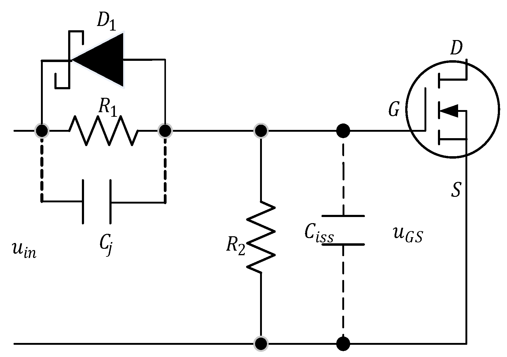
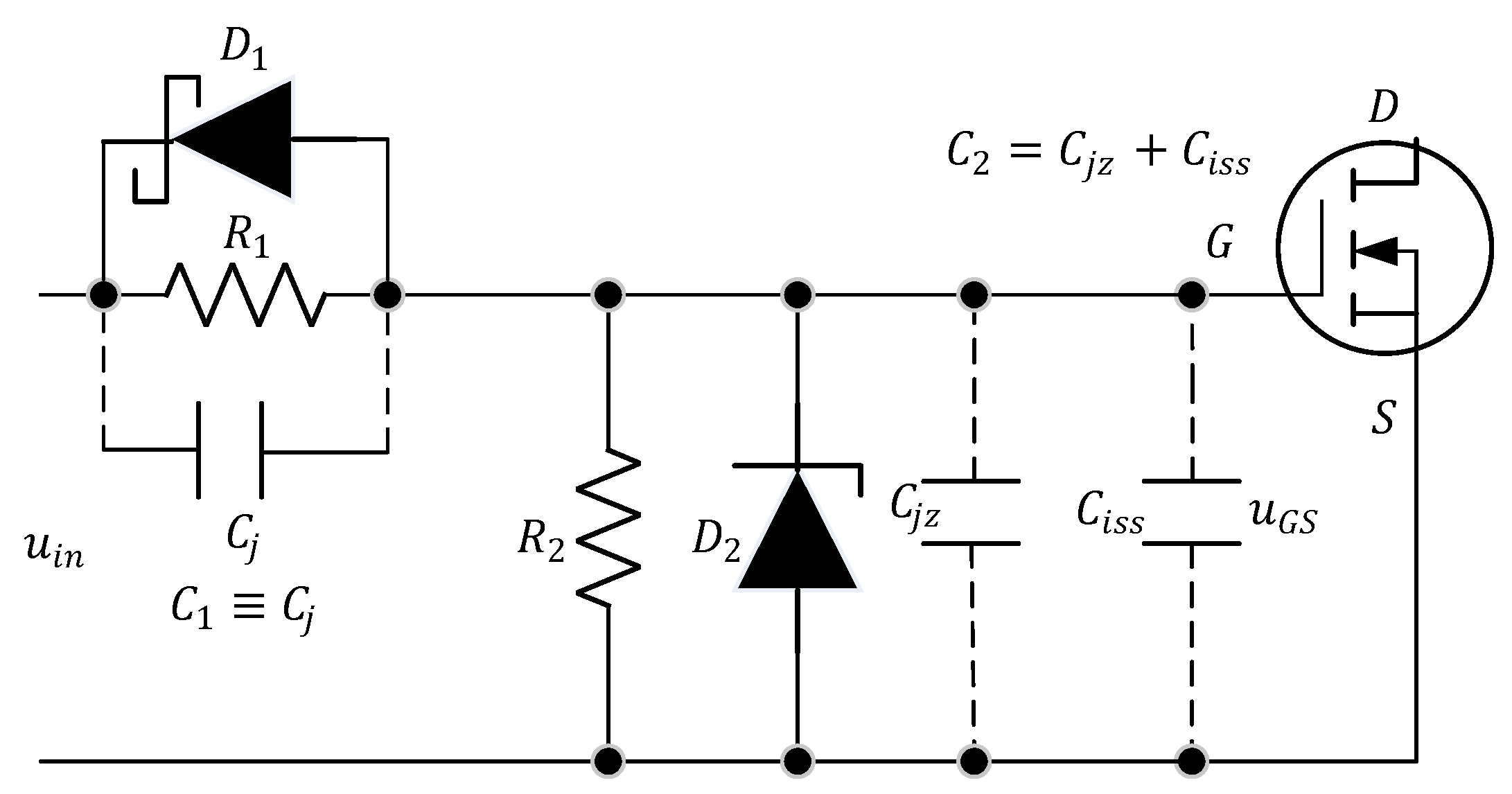
- It is recommended to implement external circuits for the gate of the transistor according to the circuit in Figure 10.
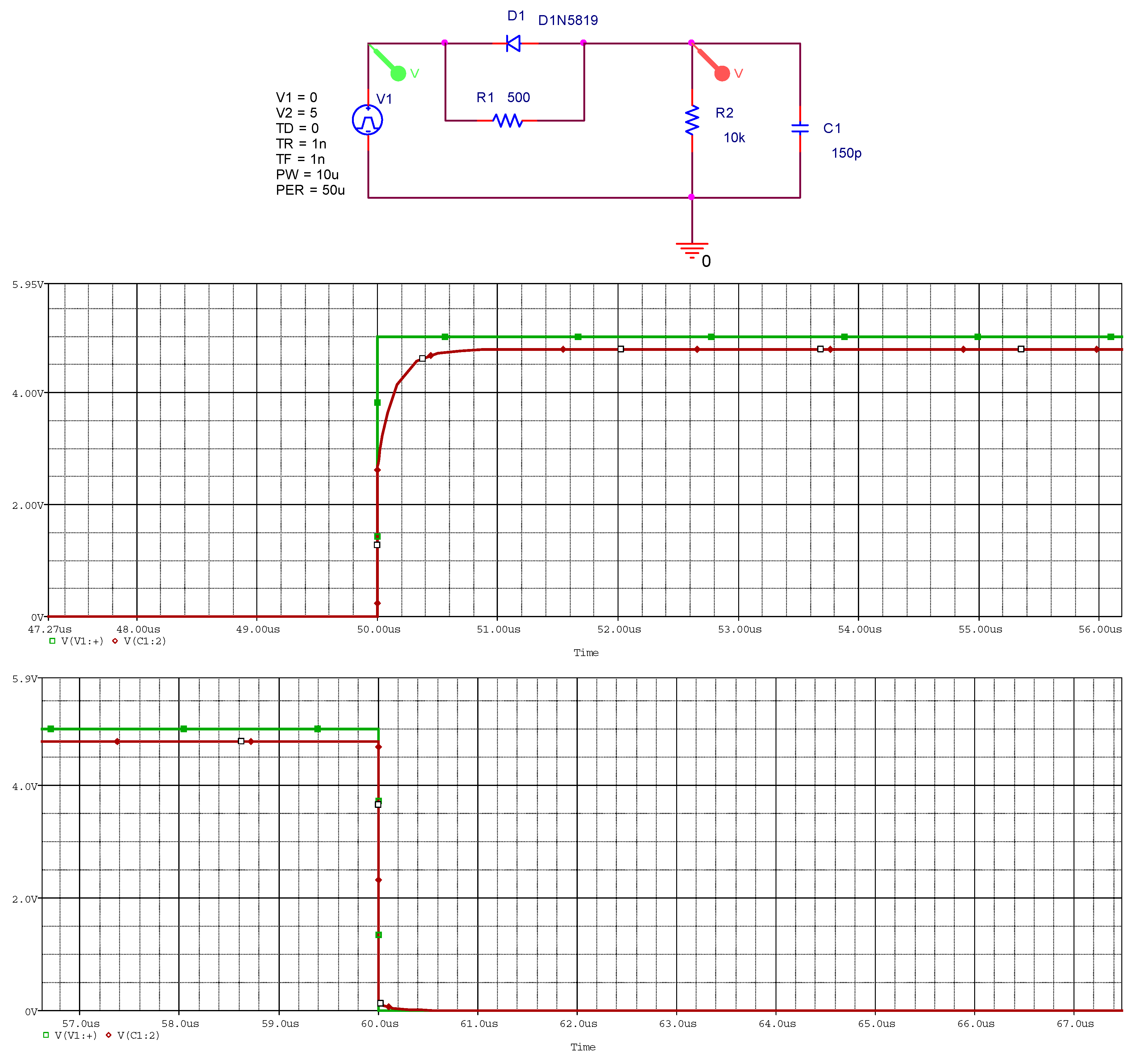
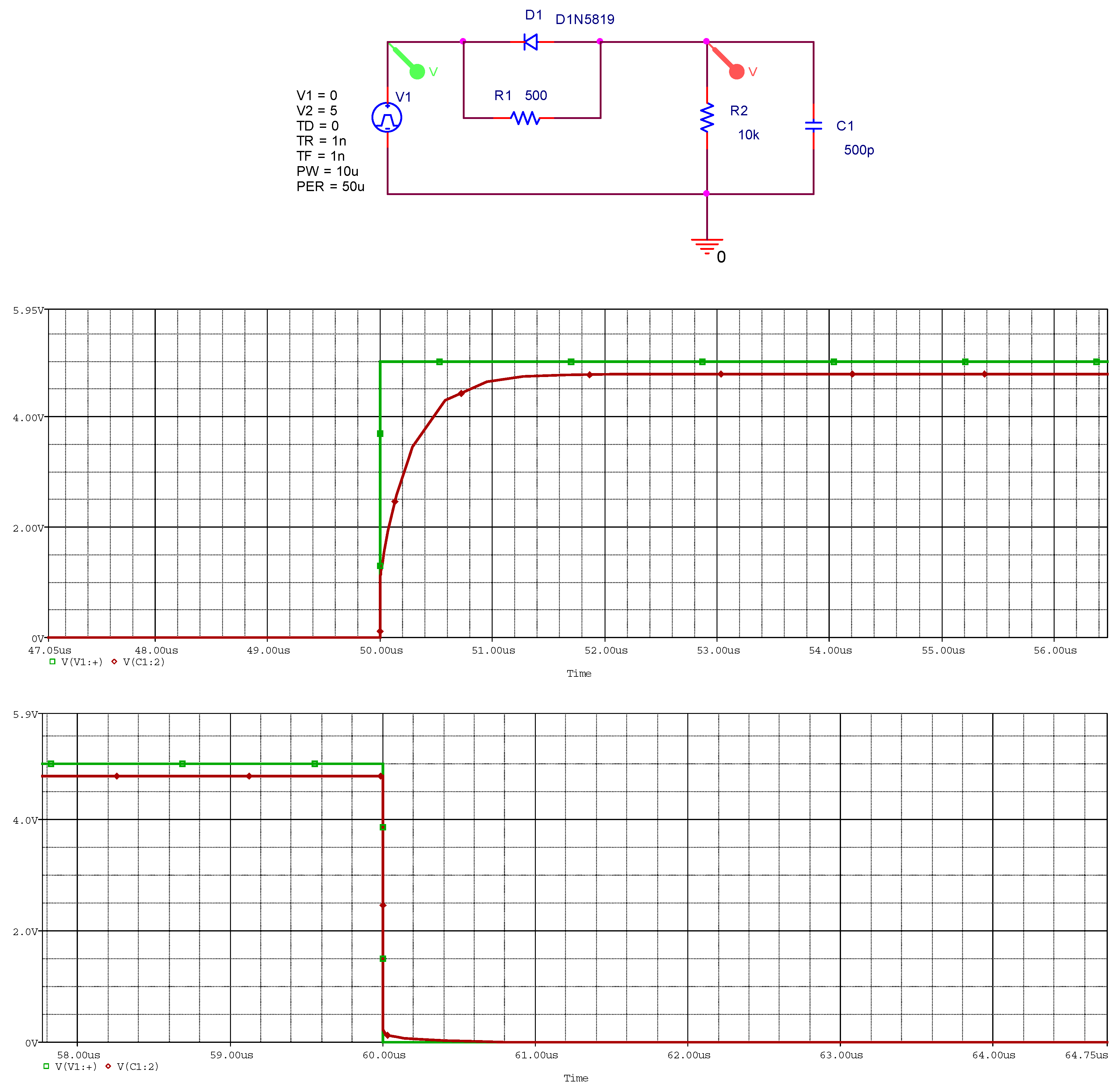
- When designing “dead time” circuits, it is necessary that the Schottky diode capacitance be significantly lower than the input capacitance of the transistor.
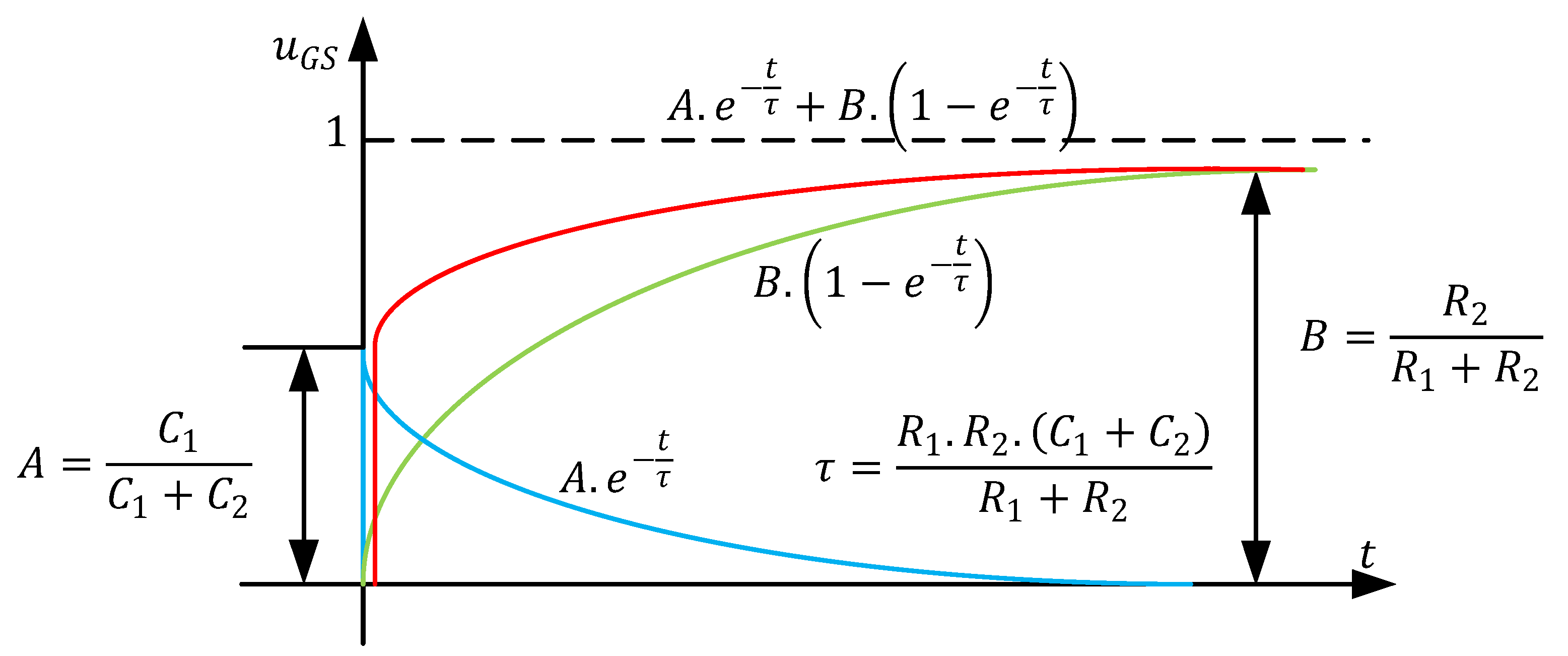
- Based on Formula (5) and Figure 6, compliance with the threshold voltage of the MOSFET must also be checked.
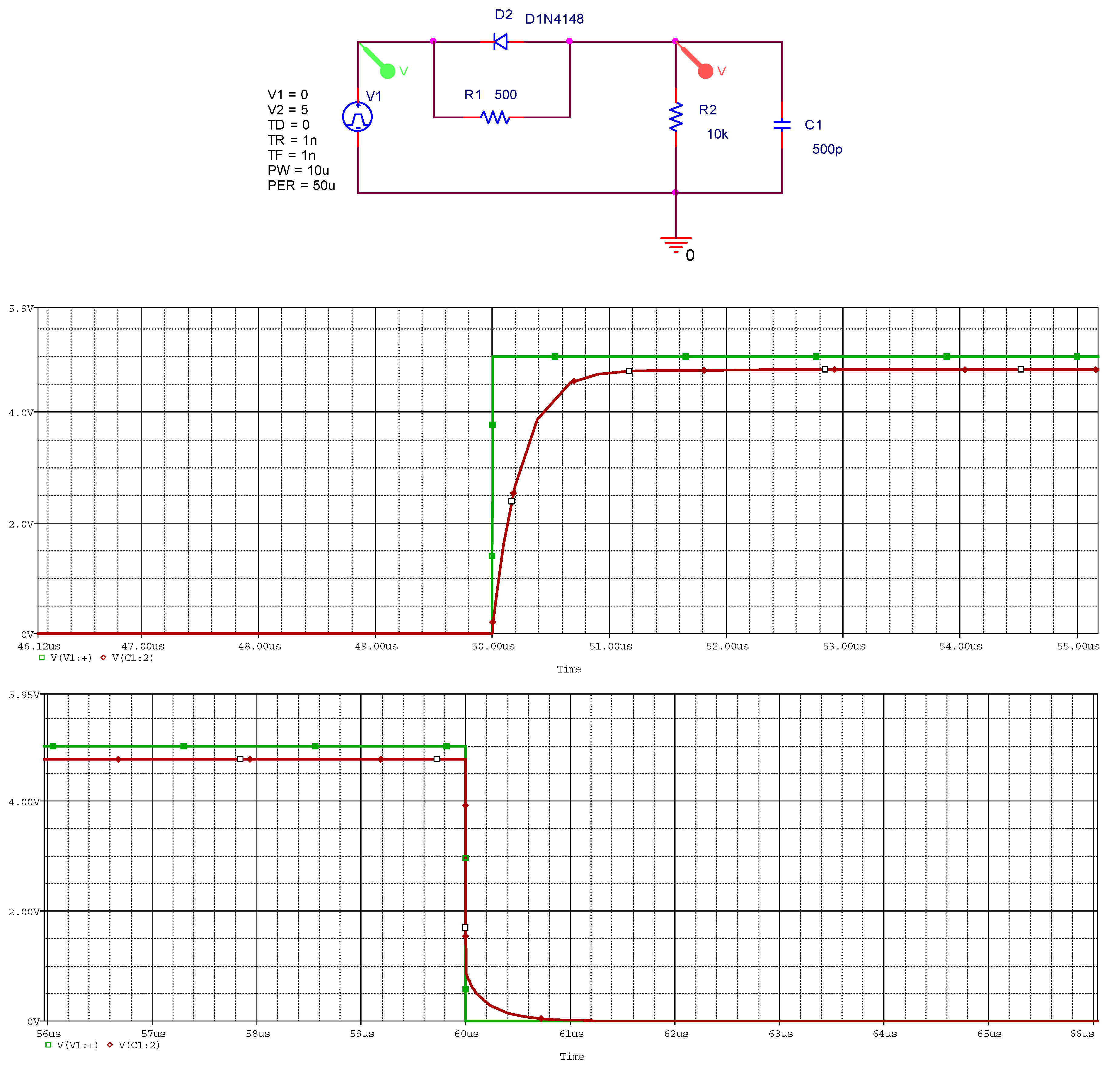
- It is not recommended to use a pulse diode with a PN junction instead of a Schottky diode due to the larger forward voltage drop across the diode with a PN junction. When the upper transistor is turned on, due to feedback capacitance, it is possible for the input capacitance of the lower transistor to be charged to a voltage higher than the threshold voltage.
- It is recommended to include Zener diodes with the lowest possible reference voltage (but greater than the maximum threshold voltage of the lower transistor) in parallel with the gate-source junction. Zener diodes with a lower reference voltage have a greater capacitance. In addition to their protective function, these diodes also facilitate the implementation of “dead time.”
- Formula (8) can be used to determine the value of “dead time” at different values of the resistor and known values of the other quantities.
Author Contributions
Funding
Data Availability Statement
Acknowledgments
Conflicts of Interest
Abbreviations
| CH | channel |
| DC | direct current |
| MOSFET | metal-oxide-semiconductor field-effect transistor |
| SMD | surface-mount device |
| Symbols | |
| capacitor | |
| diode | |
| input capacitance of a MOSFET | |
| capacitance of Schottky diode | |
| capacitance of Zener diode | |
| feedback capacitance of a MOSFET | |
| resistor | |
| time | |
| duration of “dead time” | |
| voltage | |
| gate-source voltage of a MOSFET | |
| input voltage | |
| threshold voltage of a MOSFET | |
| time constant | |
References
- Jaunay, S.; Broun, J. DC-to-DC Design Guide, Vishay Siliconix, Application Note AN607, Document Number 71917, 10 October 2002. Available online: https://www.vishay.com/docs/71917/71917.pdf (accessed on 1 December 2023).
- Hudson, T. The Difference Between CCM and DCM Explained; Article #A-0022 Rev. 1.0; Monolithic Power System: Washington, DC, USA, 2022. [Google Scholar]
- Maxim Integrated. Synchronous Rectification Aids Low-Voltage Power Supplies, Application Note 652, 31 Janunary 2001. Available online: http://www.maximintegrated.com/an652 (accessed on 1 December 2023).
- Rohm Co. Efficiency of Buck Converter, Application Note No. 64AN035E Rev.004. November 2022. Available online: https://fscdn.rohm.com/en/products/databook/applinote/ic/power/switching_regulator/buck_converter_efficiency_app-e.pdf (accessed on 1 August 2024).
- Raj, A. Calculating Efficiency, Texas Instruments Application Report SLVA390A-February 2010- Revised March 2020. Available online: https://www.ti.com/lit/an/slva390a/slva390a.pdf?ts=1740203931564&ref_url=https%253A%252F%252Fwww.google.com.hk%252F (accessed on 1 August 2024).
- He, X.; Li, D.; Zhang, V. An Accurate Approach for Calculating Efficiency of a Synchronous Buck Converter Using the MOSFET Plateau Voltage, Texas Instruments Application Report SLVAEQ9-July 2020. Available online: https://www.ti.com/lit/an/slvaeq9/slvaeq9.pdf?ts=1740124287780&ref_url=https%253A%252F%252Fwww.google.com%252F (accessed on 1 August 2024).
- Klein, J. “Shoot-through” in Synchronous Buck Converter, Fairchild, Application Note AN-6003, 25 April 2003. Available online: www.fairchildsemi.com (accessed on 1 December 2023).
- Rohm Co. Basics and Design Guidelines for Gate Drive Circuits, Application Note, No.66AN032E Rev.003, November 2023. Available online: https://fscdn.rohm.com/en/products/databook/applinote/discrete/sic/mosfet/gate_drive_circuit-design_guidelines_an-e.pdf (accessed on 1 May 2024).
- Toshiba. MOSFET Gate Drive Circuit, Application Note, 26 July 2018. Available online: https://toshiba.semicon-storage.com/info/application_note_en_20180726_AKX00068.pdf?did=59460 (accessed on 1 December 2023).
- Green, P.B.; Zheng, L.; Gate Drive for Power MOSFET in Switching Applications. A Guide for Device Characteristics and Gate Drive Techniques, Infineon Application Note, AN 2203 PL18 2204 004502, V1.0 20 April 2022. Available online: https://www.infineon.com/dgdl/Infineon (accessed on 1 December 2023).
- Texas Instruments. Fundamentals of MOSFET and IGBT Gate Drive Circuits, Application Report, SLUA618A-March2017-Revised October 2018. Available online: https://www.ti.com/lit/ml/slua618a/slua618a.pdf?ts=1740191454837&ref_url=https%253A%252F%252Fwww.perplexity.ai%252F (accessed on 1 December 2023).
- On Semiconductor. Drive and Layout Requirements for Fast Switching High Voltage MOSFETs. Available online: https://www.onsemi.co/pub/collateral/tnd6242.pdf (accessed on 1 October 2024).
- Fairchild, Design and Application Guide of Bootstrap Circuit for High-Voltage Gate-Drive IC, Application Note, AN-6076, 2008, Rev. 1.4*12/18/14. Available online: https://www.onsemi.jppub/collateral/an-6076jp.pdf (accessed on 1 December 2023).
- Ji, Y.; Yang, Y.; Zhou, J.; Ding, H.; Guo, X.; Padmanaban, S. Control strategies of mitigating dead-time effect on power converters: An overview. Electronics 2019, 8, 196. [Google Scholar] [CrossRef]
- Zhen, S.; Zhang, B.; Luo, P.; Yang, K.; Zhu, X.; Li, J. A high efficiency synchronous buck converter with adaptive dead time control for dynamic voltage scaling applications. In Proceedings of the 2011 IEEE/IFIP 19th International Conference on VLSI and System-on-Chip, Hong Kong, China, 3–5 October 2011; pp. 43–48. [Google Scholar] [CrossRef]
- Lee, S.; Jung, S.; Park, C.; Rim, C.T.; Cho, G.H. Accurate Dead-Time Control for Synchronous Buck Converter With Fast Error Sensing Circuits. IEEE Trans. Circuits Syst. I Regul. Pap. 2013, 60, 3080–3089. [Google Scholar] [CrossRef]
- Floriberto, A.L.; Santos, M.B.; Barata, J.; Aguiar, J. Dead-Time Control System for a Synchronous Buck dc-dc Converter. In Proceedings of the 2007 International Conference on Power Engineering, Energy and Electrical Drives, Setubal, Portugal, 12–14 April 2007; pp. 423–428. [Google Scholar]
- Zhou, M.; Low, Q.; Siek, L. A high efficiency synchronous buck converter with adaptive dead-time control. In Proceedings of the 2016 International Symposium on Integrated Circuits (ISIC), Singapore, 12–14 December 2016; pp. 1–4. [Google Scholar] [CrossRef]
- Yan, W.; Pi, C.; Li, W.; Liu, R. Dynamic dead-time controller for synchronous buck DC-DC converters. Electron. Lett. 2010, 46, 164–165. [Google Scholar] [CrossRef]
- Himabindu, M.; Gupta, M.; Singh, S.; Chandra, P.K.; Alkhafaji, M.A. Adaptive Dead-Time Compensation in Synchronous Buck Converters for Enhanced Efficiency in IoT Applications. In Proceedings of the 2023 International Conference on Power Energy, Environment & Intelligent Control (PEEIC), Greater Noida, India, 19–23 December 2023; pp. 408–412. [Google Scholar] [CrossRef]
- Thuc, G.H.; Chen, C.-J. An Integrated Driver With Dual-Edge Adaptive Dead-Time Control for GaN-Based Synchronous Buck Converter. IEEE Trans. Ind. Appl. 2024, 60, 9157–9170. [Google Scholar] [CrossRef]
- Lee, Y.; Kim, D.; Kim, J. A GaN Driver IC With a TDC-Based Dead-Time Controller For GaN DC-DC Buck Converters. In Proceedings of the 2023 20th International SoC Design Conference (ISOCC), Jeju, Republic of Korea, 25–28 October 2023; pp. 33–34. [Google Scholar] [CrossRef]
- Texas Instruments. TPS2836, TPS2837 Synchronous-Buck MOSFET Driver with Dead-Time Control, Application Note SLVS 224B-November 1999-Revised August 2002. Available online: https://www.ti.com/lit/ds/symlink/tps2837.pdf?ts=1740147699986 (accessed on 1 February 2025).
- Zhang, Y.; Wang, J. Understanding Dead-Time Based on TPS51225/275/285, Texas Instruments Application Report SLUA919-August 2018. Available online: https://www.ti.com/lit/an/slua919/slua919.pdf?ts=1740147700257 (accessed on 1 February 2025).
- Nexperia. Trench Schottky Diodes in Modern Swithing Applications, Application Note AN90056, Rev.1.0-9 September 2024. Available online: https://assets.nexperia.com/documents/application-note/AN90056.pdf?__hstc=13651368.2f3f33a24b44870ec4a577029c49e44b.1725840002137.1725840002138.1725840002139.1&__hssc=13651368.1.1725840002140&__hsfp=2420521548 (accessed on 1 February 2025).
- Vishay. 1N5817, 1N5818, 1N5819 Schottky Barier Plastic Rectifier, Data Sheet, Document Number 88525, Revision 1 July 2020. Available online: https://www.vishay.com/docs/88525/1n5817.pdf (accessed on 1 October 2024).
- Vishay. 1N4148WS Small Signal Switching Diode, Data Sheet, Document Number 85751, Revision 6 July 2017. Available online: https://www.vishay.com/zh/product/85751/ (accessed on 1 October 2024).
- On Semiconductors. BZX84C3V3- BZX84C33 Zeners, Data Sheet, November 2015. Available online: https://media.digikey.com/pdf/Data%20Sheets/ON%20Semiconductor%20PDFs/BZX84C3V3-C33_Rev1.10_Nov2015.pdf (accessed on 1 October 2024).
- Infineon. BSS214N OptiMOS 2 Small-Signal Transistor, Data Sheet, Rev.2, 08-07-2011. Available online: https://www.infineon.com/dgdl/Infineon-BSS214N-DS-v02_03-en.pdf?fileId=db3a304330f6860601311828a70444e9 (accessed on 1 October 2024).
- Vishay. SS32, SS33, SS34, SS35, SS36 Surface-Mount Schottky Barier Rectifier, Data Sheet, Document Number 88751, 23-April-2020. Available online: https://www.vishay.com/docs/88751/ss32.pdf (accessed on 1 October 2024).
- Vishay. SS12, SS13, SS14, SS15, SS16 SS36 Surface-Mount Schottky Barier Rectifier, Data Sheet, Document Number 88746, 23-April-2020. Available online: https://www.vishay.com/docs/88746/ss12.pdf (accessed on 1 October 2024).
- Bakhordarian, V. Power MOSFET Basics, International Rectifier, an-1084, p1–p65. Available online: https://www.tayloredge.com/reference/Electronics/Semiconductors/mosfetbasics.pdf (accessed on 1 October 2024).
- Unisonic Technologies. UT6402 Power MOSFET N-Channel Enhancement Mode, Document No QW-502-152E, 2023. Available online: https://www.unisonic.com.tw/uploadfiles/836/part_no_pdf/UT6402.pdf (accessed on 1 October 2024).


| Schottky Diode (Diode) Capacitance, pF | Transistor, Zener Diode Capacitance, pF | Value of A, Starting Voltage G-S at 3 V from the Driver, V | , min. Value, V | |
|---|---|---|---|---|
| Variant 1 | SS34, | BSS214N, | 0.837, 2.51 V | 0.7 |
| Variant 2 | SS34, | UT6402G, | 0.654, 1.962 V | 1.0 |
| Variant 3 | SS14, | UT6402G, | 0.345, 1.035 V | 1.0 |
| Variant 4 | SS14, | UT6402G, , BZM55C5V1, | 0.277, 0.831 V | 1.0 |
| Variant 5 | 1N4148W-G, | UT6402G, | 0.0075, 0.0225 V | 1.0 |
| Variant 6 | 1N4148W-G, | UT6402G, , BZM55C5V1, | 0.00544, 0.0163 V | 1.0 |
| Schottky Diode (Diode), Forward Voltage, V Driver Output Low Voltage, V | Value of Starting Voltage G-S at 3 V from D-S,V | , min. Value, V | ||
|---|---|---|---|---|
| Variant 4 | SS14, , LPV7215, Total, 0.6 V < 1 V | UT6402G, , BZM55C5V1, | 0.4 V | 1.0 |
| Variant 5 | 1N4148W-G, LPV7215, Total, 1.05 V > 1 V | UT6402G, | 0.523 V | 1.0 |
| Variant 6 | 1N4148W-G, LPV7215, Total, 1.05 V > 1 V | UT6402G, , BZM55C5V1, | 0.4 V | 1.0 |
Disclaimer/Publisher’s Note: The statements, opinions and data contained in all publications are solely those of the individual author(s) and contributor(s) and not of MDPI and/or the editor(s). MDPI and/or the editor(s) disclaim responsibility for any injury to people or property resulting from any ideas, methods, instructions or products referred to in the content. |
© 2025 by the authors. Licensee MDPI, Basel, Switzerland. This article is an open access article distributed under the terms and conditions of the Creative Commons Attribution (CC BY) license (https://creativecommons.org/licenses/by/4.0/).
Share and Cite
Antchev, H.; Borisov, D. On the Implementation of “Dead Time” in a Synchronous Step-Down Converter. Energies 2025, 18, 1095. https://doi.org/10.3390/en18051095
Antchev H, Borisov D. On the Implementation of “Dead Time” in a Synchronous Step-Down Converter. Energies. 2025; 18(5):1095. https://doi.org/10.3390/en18051095
Chicago/Turabian StyleAntchev, Hristo, and Dimitar Borisov. 2025. "On the Implementation of “Dead Time” in a Synchronous Step-Down Converter" Energies 18, no. 5: 1095. https://doi.org/10.3390/en18051095
APA StyleAntchev, H., & Borisov, D. (2025). On the Implementation of “Dead Time” in a Synchronous Step-Down Converter. Energies, 18(5), 1095. https://doi.org/10.3390/en18051095